EP1846941B1 - Zirconia toughened alumina composition and use in ion and electron optical systems - Google Patents
Zirconia toughened alumina composition and use in ion and electron optical systems Download PDFInfo
- Publication number
- EP1846941B1 EP1846941B1 EP06734522.3A EP06734522A EP1846941B1 EP 1846941 B1 EP1846941 B1 EP 1846941B1 EP 06734522 A EP06734522 A EP 06734522A EP 1846941 B1 EP1846941 B1 EP 1846941B1
- Authority
- EP
- European Patent Office
- Prior art keywords
- components
- ionizer
- optical system
- ion
- volume
- Prior art date
- Legal status (The legal status is an assumption and is not a legal conclusion. Google has not performed a legal analysis and makes no representation as to the accuracy of the status listed.)
- Expired - Lifetime
Links
Images



Classifications
-
- H—ELECTRICITY
- H01—ELECTRIC ELEMENTS
- H01J—ELECTRIC DISCHARGE TUBES OR DISCHARGE LAMPS
- H01J49/00—Particle spectrometers or separator tubes
-
- C—CHEMISTRY; METALLURGY
- C04—CEMENTS; CONCRETE; ARTIFICIAL STONE; CERAMICS; REFRACTORIES
- C04B—LIME, MAGNESIA; SLAG; CEMENTS; COMPOSITIONS THEREOF, e.g. MORTARS, CONCRETE OR LIKE BUILDING MATERIALS; ARTIFICIAL STONE; CERAMICS; REFRACTORIES; TREATMENT OF NATURAL STONE
- C04B35/00—Shaped ceramic products characterised by their composition; Ceramics compositions; Processing powders of inorganic compounds preparatory to the manufacturing of ceramic products
- C04B35/01—Shaped ceramic products characterised by their composition; Ceramics compositions; Processing powders of inorganic compounds preparatory to the manufacturing of ceramic products based on oxide ceramics
- C04B35/10—Shaped ceramic products characterised by their composition; Ceramics compositions; Processing powders of inorganic compounds preparatory to the manufacturing of ceramic products based on oxide ceramics based on aluminium oxide
- C04B35/111—Fine ceramics
- C04B35/117—Composites
- C04B35/119—Composites with zirconium oxide
-
- C—CHEMISTRY; METALLURGY
- C04—CEMENTS; CONCRETE; ARTIFICIAL STONE; CERAMICS; REFRACTORIES
- C04B—LIME, MAGNESIA; SLAG; CEMENTS; COMPOSITIONS THEREOF, e.g. MORTARS, CONCRETE OR LIKE BUILDING MATERIALS; ARTIFICIAL STONE; CERAMICS; REFRACTORIES; TREATMENT OF NATURAL STONE
- C04B35/00—Shaped ceramic products characterised by their composition; Ceramics compositions; Processing powders of inorganic compounds preparatory to the manufacturing of ceramic products
- C04B35/01—Shaped ceramic products characterised by their composition; Ceramics compositions; Processing powders of inorganic compounds preparatory to the manufacturing of ceramic products based on oxide ceramics
- C04B35/48—Shaped ceramic products characterised by their composition; Ceramics compositions; Processing powders of inorganic compounds preparatory to the manufacturing of ceramic products based on oxide ceramics based on zirconium or hafnium oxides, zirconates, zircon or hafnates
- C04B35/486—Fine ceramics
- C04B35/488—Composites
- C04B35/4885—Composites with aluminium oxide
Definitions
- This invention relates to ion and electron optical systems. More particularly, this system relates to ion and electron optical systems comprising a Zirconia Toughened Alumina (“ZTA”) composition.
- ZTA Zirconia Toughened Alumina
- the present invention relates to ion and electron optical systems, such as mass spectrometer ("MS") systems.
- Mass spectrometer systems may, for example, be used to analyze the chemical composition of subject samples. Generally, such systems ionize the atoms and molecules present in a subject sample. Once ionized, the ions are transferred into a mass analysis region where they are separated, or filtered, according to their mass-to-charge ratio (m/z) to create a mass spectrum. A charged-particle detector of the mass spectrometer system then analyzes the ions in order to identify their mass and velocity distribution. From this, information useful in characterizing the chemical composition of the sample can be determined.
- m/z mass-to-charge ratio
- mass spectrometer systems generally require a reduced pressure environment and therefore include a vacuum system for lowering the pressure throughout.
- mass spectrometer systems also include an ionization source such as an electron ionizer (“EI”) or chemical ionizer (“CI”).
- EI electron ionizer
- CI chemical ionizer
- mass spectrometer systems further includes a gas chromatograph to separate volatile and non-volatile compounds prior to providing them for ionization.
- the systems generally also include a mass separator or mass analyzer.
- the mass separator includes an electromagnet for deflecting ions in the beam. Depending on the mass and charge of the ions, the magnitude of deflection varies. Generally ions having a higher mass deflect less. Species of ions present in the sample may therefore be separately studied by varying the magnetic field.
- the mass separator includes a quadrupole mass filter consisting of four parallel rods.
- two opposite rods may have a positive applied potential while the other two rods have a negative potential.
- the applied voltages affect the trajectory of ions traveling down the flight path centered between the four rods. For given voltages, only ions of a certain mass-to-charge ratio pass through the quadrupole filter and all other ions are thrown out of their original path. A mass spectrum may therefore be generated by varying the voltages.
- U.S. Patent Application Publication No. 2004/124149A1 to Boschetti discloses solid substrates and processes for making and using them in the context of separation science and analytical biochemistry.
- the solid substrate may be an organic material or, alternatively, an inorganic material such as hydrogel-containing silica, zirconia, alumina, titania, ceramics, and mixtures thereof.
- the solid substrate is a mass spectrometer probe that can be used to introduce ions into the spectrometer.
- U.S. Patent No. 5,852,294 A to Gulcicek describes a miniature multipole rod assembly which can be operated as an ion guide or a mass analyzer. Gulcicek discloses quadrupole mass analyzers and an ion trap. Individual rods are bonded to plates and separated by ceramic insulators.
- JP 11025903 A relates to a metal-ceramic composite sampler and skimmer and discloses that for a ceramic part it is used a ceramic material such as high heat resistance temperature alumina, zirconia, magnesia or the like.
- US 6,140,640 A refers to an electrospray device and discloses that a non-conductive tube might be of materials like for example ceramic materials such as alumina or zirconia or the like.
- alumina (Al2O3) is one of the most widely specified, general-purpose technical ceramics and refers to options including blends of zirconia with alumina and silicon nitride with alumina with the result of a performance combination that is tougher than alumina alone, but with improved hardness, strengths and thermal properties.
- Anonymous: " Advanced ceramics", 16 January 2005 (2005-01-16), XP055225653 discloses two alumina products, a zirconia, a zirconia toughened alumina and a glass ceramic.
- ZTA-96 zirconia toughened alumina 6 December 2004 (2004-12-06), XP05522593 , it is known that ZTA-96 is a zirconia toughened alumina ceramic that exhibits excellent wear and corrosion resistance along with high strengths and toughness.
- the various components of ion and electron optical systems are subject to high temperatures, stress, and contact with any number of chemical compounds.
- ceramics have been used for various components due to their desirable chemical and electrical properties.
- the ceramics which are presently used often do not provide the necessary structural strength and are, therefore, prone to fracture damage or breakage.
- the thermal expansion of adjacent metal components causes the ceramic components to break. This can cause misalignment, ceramic dust contamination and electrical insulation breakdown in the mass spectrometer.
- Other materials which are used in ion and electron optical systems have better strength capabilities, but are unstable and lose electrical insulation properties at high temperatures.
- an ion optical system comprising an ionizer for ionizing one or more compounds, said ionizer comprising a plurality of components, a mass separator for separating ions of the one or more compounds, said mass separator comprising a plurality of components, and a detector for identifying the one or more compounds, said detector comprising a plurality of components, wherein at least one of the plurality of components of at least one of said ionizer, said mass separator and said detector is an isolator for isolating one or more components, the isolator comprises a composition consisting essentially of approximately 80 % aluminum oxide by volume and approximately 20% zirconium oxide by volume and wherein the isolator maintains greater than 1 x 10 12 ohms of resistance at 350° C.
- Dependent claims 2 - 9 refer to preferred embodiments.
- a method of isolating one or more components of ion optical system comprising the steps of providing an ionizer for ionizing one or more compounds, said ionizer comprising a plurality of components, providing a mass separator for separating ions of the one or more compounds, said mass separator comprising a plurality of components, and providing a detector for identifying the one or more compounds, said detector comprising a plurality of components, providing at least one isolator for isolating at least one of the plurality of components of at least one of the ionizer, the mass separator, and the detector, wherein the isolator comprises a composition consisting essentially of approximately 80 % aluminum oxide by volume and approximately 20% zirconium oxide by volume and wherein the isolator maintains greater than 1 x 10 12 ohms of resistance at 350° C.
- Dependent claims 11 - 13 refer to preferred embodiments.
- FIG. 1 shows an exemplary ion and electron optical system according to one embodiment of the present invention.
- the system may be one or more of many ion and/or electron optical systems or vacuum systems.
- the system may be a gas chromatograph mass spectrometer system.
- the exemplary system shown in FIG. 1 includes a means to ionize a sample (e.g., chemical compound), or an ionizer 102.
- the ionizer 102 may be one or more of many ionizers, such as an electron ionizer (e.g., electron impact ionizer) and/or a chemical ionizer.
- the ionizer 102 may include an electrospray ionizer ("ESI”) or an atmospheric pressure chemical ionizer (“APCI”). Further included in the system may be a gas chromatograph and/or liquid chromatograph to separate volatile and non-volatile compounds prior to providing them for ionization.
- EI electrospray ionizer
- APCI atmospheric pressure chemical ionizer
- gas chromatograph and/or liquid chromatograph to separate volatile and non-volatile compounds prior to providing them for ionization.
- the system may include a mass separator 110 or mass analyzer.
- the mass separator 110 may be one of many types of mass separators or means to separate or filter ions according to their mass-to-charge ratio (m/z).
- the mass separator 110 is a quadrupole mass analyzer or separator having at least four quadrupoles (e.g., quadrupoles 118 shown in FIG. 2 ) or quads.
- the mass separator 110, or a portion thereof, may be supported and/or aligned by one or more supports, such as supports 112 and 114 (e.g., quad supports).
- the mass separator 110 may further include a pre-filter 116, e.g., having pre-filter quadrupoles 117.
- the pre-filter 116 may operate to improve sensitivity of the mass separator 110 and prevent contamination of the quadrupoles 118 with ion deposits.
- the system according to the illustrated embodiment may further include a detector 120 (e.g., ion detector).
- the detector 120 may be one or more of many types of detectors such as a Faraday cup, an electron multiplier or a photomultiplier detector.
- the detector 120 is a photomultiplier detector.
- the detector 120 may include a conversion dynode 122 and phosphor plate 124. Generally ions emerging from the mass separator 110 will strike the dynode 122 resulting in electrons being emitted towards the phosphor plate 124. Electrons striking the phosphor plate 124 are converted into photons.
- the photons are then amplified via a photomultiplier 126 (e.g., at a gain of 10 5 ) and evaluated.
- a photomultiplier 126 e.g., at a gain of 10 5
- the detector 120 may include additional components as required to identify and/or quantitate compounds. Further, the detector 120 may include a communication link to transmit detection data to a computer and/or user interface.
- the ionizer 102 may include two or more portions.
- the ionizer 102 may include an inner ion source 104 and an outer ion source 106.
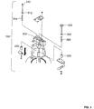
- FIG. 3 is an exploded view of the inner ion source 104.
- the inner ion source 104 includes many components and/or subcomponents which require high temperature capability, strength, fracture toughness, chemical inertness, and high temperature electrical insulation/isolation.
- the inner ion source 104 includes a housing 302 supporting an electron trap 310 and repeller 320.
- the electron trap 310 attracts negative ions and electrons to the repeller 320 which then directs the ions out of the inner ion source 104 and to the mass separator 110.
- the electron trap 310 and repeller 320 may further include several spacers (e.g., 2mm, 6mm, 12mm spacers).
- the inner ion source 104 may include spacers 312, 314, 316 and spacers 322, 324, 326.
- some of the above described components of the inner ion source 104 comprise an optimized composition of zirconium oxide (ZrO 2 ) and aluminum oxide (Al 2 O 3 ) or zirconia toughened alumina ("ZTA").
- the compositions can provide increased strength over presently used ceramics while providing electrical insulative properties up to at least 350°C.
- spacers may be used in part to electrically isolate particular components such as the electron trap 310 and/or repeller 320.
- any one or all of the spacers 312-316 and 322-326 according to the present invention may comprise the composition of zirconium oxide and aluminium oxide.
- some spacers that require additional electrical insulation but less fracture toughness and strength comprise the composition consisting essentially of approximately 80% aluminum oxide by volume and approximately 20% zirconium oxide by volume. Spacers comprising this particular composition may maintain greater than 1x10 12 ohms of resistance at 350°C.
- the inner ion source 104 may also employ chemical ionization, either alone or in combination with the above described electron ionization.
- a chemical ionizer (not shown) may not include the electron trap 310 and repeller 320.
- any number of ZTA spacers would likewise be used to electrically isolate components thereof.
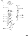
- Fig. 4 shows one outer ion source 106 for an ion optical system according to the illustrated embodiment.
- the outer ion source 106 may include numerous components such as an ion block 402, one or more lenses 404/406, and one or more contact terminals 408.
- the outer source 106 may also include one or more heaters (shown in FIG. 5 ) to raise the source temperature high enough to prevent molecules in the sample from condensing.
- Further included in the outer ion source 106 may be several (e.g., four or more) structural rods 410 for supporting and/or aligning the outer ion source 106.
- the outer ion source 106 also includes any number of spacers for isolating and/or separating various portions or components of the outer ion source 106.
- any one or several of the components of the outer ion source 106 may also comprise a composition of zirconium oxide and aluminum oxide as described above, e.g., to provide improved structural strength and electrical insulation, higher temperature capability, and improved chemical inertness.
- the structural rods 410 may comprise the composition.
- the rods 410 according to the illustrated embodiment therefore provide chemically inert support for the outer ion source 106 with high electrical insulation properties.
- the rods 410 according to the illustrated embodiment thus may be less prone to breakage and intermittent shorts as is prevalent in the prior art systems.
- the outer ion source 106 further includes numerous spacers, e.g., spacers 412-424. Any one or several of the spacers may also be made from a composition of zirconium oxide and aluminum oxide. The use of spacers comprising such composition in the outer ion source 106 provides superior performance (e.g., electrical isolation performance) and allows the spacers to resist breaking under thermal expansion.
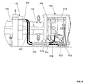
- FIG. 5 shows a side view of a portion of the ion optical system and, in particular, the ionizer 102.
- One of the supports 112/114 of the mass separator 110 is also shown.
- the mass separator 110 is a finely machined assembly which must be precisely aligned and supported. It is desired that the supports 112/114 maintain the required alignment, withstand high temperature and contact with any number of chemical compounds, and act as an electrical isolator. Therefore, in the illustrated embodiment, the supports 112/114 comprise an above described composition of zirconium oxide and aluminum oxide.
- the system may include different numbers of heaters, or heater cartridges 502 and 504, for providing heat to the quadrupoles 118 and/or ionizer 102.
- the wiring for the heater cartridges, as well as for other components of the system, generally requires an isolator means to provide wire mobility, insulation and electrical isolation.
- the system therefore includes one or more beads, such as beads 510-516 and 520-522. As shown, multiple beads may be employed in series, e.g., on a heater lead or other wire of the system.
- FIGS. 6A and 6B show additional exemplary beads 602-606 according the illustrated embodiment.
- the beads comprise a composition of zirconium oxide and aluminum oxide as disclosed herein to provide insulation/isolation without being prone to breakage.
- the composition includes approximately 80% aluminum oxide by volume and approximately 20% zirconium oxide by volume. Therefore, the beads according to the present teachings can prevent the wiring from contacting with other components of the system which may lead to electrical shorts or other serious malfunctions of the system.
Landscapes
- Chemical & Material Sciences (AREA)
- Engineering & Computer Science (AREA)
- Ceramic Engineering (AREA)
- Composite Materials (AREA)
- Materials Engineering (AREA)
- Manufacturing & Machinery (AREA)
- Structural Engineering (AREA)
- Organic Chemistry (AREA)
- Analytical Chemistry (AREA)
- Other Investigation Or Analysis Of Materials By Electrical Means (AREA)
- Electron Tubes For Measurement (AREA)
- Investigating Or Analyzing Non-Biological Materials By The Use Of Chemical Means (AREA)
- Analysing Materials By The Use Of Radiation (AREA)
Description
- Applicant claims priority benefits of pending U.S. Patent Application filed on February 7, 2006 and U.S. Provisional Patent Application Serial No.
60/650,881 filed on February 8, 2005 - This invention relates to ion and electron optical systems. More particularly, this system relates to ion and electron optical systems comprising a Zirconia Toughened Alumina ("ZTA") composition.
- The present invention relates to ion and electron optical systems, such as mass spectrometer ("MS") systems. Mass spectrometer systems may, for example, be used to analyze the chemical composition of subject samples. Generally, such systems ionize the atoms and molecules present in a subject sample. Once ionized, the ions are transferred into a mass analysis region where they are separated, or filtered, according to their mass-to-charge ratio (m/z) to create a mass spectrum. A charged-particle detector of the mass spectrometer system then analyzes the ions in order to identify their mass and velocity distribution. From this, information useful in characterizing the chemical composition of the sample can be determined.
- Ion and electron optical systems, such as mass spectrometer systems, generally require a reduced pressure environment and therefore include a vacuum system for lowering the pressure throughout. To ionize the sample, mass spectrometer systems also include an ionization source such as an electron ionizer ("EI") or chemical ionizer ("CI"). One type of mass spectrometer system, a gas chromatograph ("GC") mass spectrometer system, further includes a gas chromatograph to separate volatile and non-volatile compounds prior to providing them for ionization.
- The systems generally also include a mass separator or mass analyzer. In some systems, the mass separator includes an electromagnet for deflecting ions in the beam. Depending on the mass and charge of the ions, the magnitude of deflection varies. Generally ions having a higher mass deflect less. Species of ions present in the sample may therefore be separately studied by varying the magnetic field.
- In some other systems, the mass separator includes a quadrupole mass filter consisting of four parallel rods. For example, two opposite rods may have a positive applied potential while the other two rods have a negative potential. The applied voltages affect the trajectory of ions traveling down the flight path centered between the four rods. For given voltages, only ions of a certain mass-to-charge ratio pass through the quadrupole filter and all other ions are thrown out of their original path. A mass spectrum may therefore be generated by varying the voltages.
U.S. Patent Application Publication No.2004/124149A1 to Boschetti discloses solid substrates and processes for making and using them in the context of separation science and analytical biochemistry. The solid substrate may be an organic material or, alternatively, an inorganic material such as hydrogel-containing silica, zirconia, alumina, titania, ceramics, and mixtures thereof. In one embodiment, the solid substrate is a mass spectrometer probe that can be used to introduce ions into the spectrometer.
U.S. Patent No. 5,852,294 A to Gulcicek describes a miniature multipole rod assembly which can be operated as an ion guide or a mass analyzer. Gulcicek discloses quadrupole mass analyzers and an ion trap. Individual rods are bonded to plates and separated by ceramic insulators.JP 11025903 A US 6,140,640 A refers to an electrospray device and discloses that a non-conductive tube might be of materials like for example ceramic materials such as alumina or zirconia or the like. From Anonymous "Zirconia toughened Alumina", 14 October 2004 (2004-10-14), XP055225769, discloses that alumina (Al2O3) is one of the most widely specified, general-purpose technical ceramics and refers to options including blends of zirconia with alumina and silicon nitride with alumina with the result of a performance combination that is tougher than alumina alone, but with improved hardness, strengths and thermal properties. Anonymous: "Advanced ceramics", 16 January 2005 (2005-01-16), XP055225653, discloses two alumina products, a zirconia, a zirconia toughened alumina and a glass ceramic. From Anonymous: "ZTA-96 zirconia toughened alumina", 6 December 2004 (2004-12-06), XP05522593, it is known that ZTA-96 is a zirconia toughened alumina ceramic that exhibits excellent wear and corrosion resistance along with high strengths and toughness. - The various components of ion and electron optical systems are subject to high temperatures, stress, and contact with any number of chemical compounds. Traditionally, ceramics have been used for various components due to their desirable chemical and electrical properties. However, the ceramics which are presently used often do not provide the necessary structural strength and are, therefore, prone to fracture damage or breakage. Often, the thermal expansion of adjacent metal components causes the ceramic components to break. This can cause misalignment,
ceramic dust contamination and electrical insulation breakdown in the mass spectrometer. Other materials which are used in ion and electron optical systems have better strength capabilities, but are unstable and lose electrical insulation properties at high temperatures. - According, it is an object of the present invention to provide a composition or material for use in ion and electron optical systems.
- It is also an object to provide an ion and electron optical system in which one or more components thereof comprise a composition or material which provides strength, chemical inertness, and insulation.
- It is also an object to provide a method to isolate components of an ion and electron optical system.
- These and other objectives are achieved by providing an ion optical system comprising an ionizer for ionizing one or more compounds, said ionizer comprising a plurality of components, a mass separator for separating ions of the one or more compounds, said mass separator comprising a plurality of components, and a detector for identifying the one or more compounds, said detector comprising a plurality of components, wherein at least one of the plurality of components of at least one of said ionizer, said mass separator and said detector is an isolator for isolating one or more components, the isolator comprises a composition consisting essentially of approximately 80 % aluminum oxide by volume and approximately 20% zirconium oxide by volume and wherein the isolator maintains greater than 1 x 10¹² ohms of resistance at 350° C. Dependent claims 2 - 9 refer to preferred embodiments.
- Further provided is a method of isolating one or more components of ion optical system, comprising the steps of providing an ionizer for ionizing one or more compounds, said ionizer comprising a plurality of components, providing a mass separator for separating ions of the one or more compounds, said mass separator comprising a plurality of components, and providing a detector for identifying the one or more compounds, said detector comprising a plurality of components, providing at least one isolator for isolating at least one of the plurality of components of at least one of the ionizer, the mass separator, and the detector, wherein the isolator comprises a composition consisting essentially of approximately 80 % aluminum oxide by volume and approximately 20% zirconium oxide by volume and wherein the isolator maintains greater than 1 x 10¹² ohms of resistance at 350° C. Dependent claims 11 - 13 refer to preferred embodiments.
- Other objects, features and advantages according to the present invention will become apparent from the following detailed description of certain illustrated embodiments when read in conjunction with the accompanying drawings in which the same components are identified by the same reference numerals.
-
-
FIG. 1 is a side view of one ion optical system according to the present invention. -
FIG. 2 is a perspective view of an ion optics portion of an ion optical system according toFIG. 1 . -
FIG. 3 is an exploded view of an inner ion source of an ion optical system according toFIG. 1 . -
FIG. 4 is an exploded view of an outer ion source of an ion optical system according toFIG. 1 . -
FIG. 5 is another side view of an ion optical system according toFIG. 1 . -
FIG. 6A is a cutaway view of electrical connector of an ion optical system according toFIGS. 1 and5 . -
FIG. 6B is a cutaway view of electrical bead of an ion optical system according toFIGS. 1 and5 . -
FIG. 1 shows an exemplary ion and electron optical system according to one embodiment of the present invention. The system may be one or more of many ion and/or electron optical systems or vacuum systems. For example, the system may be a gas chromatograph mass spectrometer system. The exemplary system shown inFIG. 1 includes a means to ionize a sample (e.g., chemical compound), or anionizer 102. Theionizer 102 may be one or more of many ionizers, such as an electron ionizer (e.g., electron impact ionizer) and/or a chemical ionizer. In some embodiments, theionizer 102 may include an electrospray ionizer ("ESI") or an atmospheric pressure chemical ionizer ("APCI"). Further included in the system may be a gas chromatograph and/or liquid chromatograph to separate volatile and non-volatile compounds prior to providing them for ionization. - Also shown in
FIG. 1 , the system may include amass separator 110 or mass analyzer. As one of ordinary skill in the art will understand, themass separator 110 may be one of many types of mass separators or means to separate or filter ions according to their mass-to-charge ratio (m/z). In the illustrated embodiment, themass separator 110 is a quadrupole mass analyzer or separator having at least four quadrupoles (e.g.,quadrupoles 118 shown inFIG. 2 ) or quads. Themass separator 110, or a portion thereof, may be supported and/or aligned by one or more supports, such assupports 112 and 114 (e.g., quad supports). Themass separator 110 may further include a pre-filter 116, e.g., havingpre-filter quadrupoles 117. The pre-filter 116 may operate to improve sensitivity of themass separator 110 and prevent contamination of thequadrupoles 118 with ion deposits. - The system according to the illustrated embodiment may further include a detector 120 (e.g., ion detector). The
detector 120 may be one or more of many types of detectors such as a Faraday cup, an electron multiplier or a photomultiplier detector. In the illustrated embodiment, thedetector 120 is a photomultiplier detector. Shown better inFIG. 2 , thedetector 120 may include aconversion dynode 122 andphosphor plate 124. Generally ions emerging from themass separator 110 will strike thedynode 122 resulting in electrons being emitted towards thephosphor plate 124. Electrons striking thephosphor plate 124 are converted into photons. The photons are then amplified via a photomultiplier 126 (e.g., at a gain of 105) and evaluated. As one of ordinary skill in the art will understand, thedetector 120 may include additional components as required to identify and/or quantitate compounds. Further, thedetector 120 may include a communication link to transmit detection data to a computer and/or user interface. - Also shown in
FIG. 2 , theionizer 102 may include two or more portions. For example, theionizer 102 may include aninner ion source 104 and anouter ion source 106.FIG. 3 is an exploded view of theinner ion source 104. Theinner ion source 104 includes many components and/or subcomponents which require high temperature capability, strength, fracture toughness, chemical inertness, and high temperature electrical insulation/isolation. For example, theinner ion source 104 includes ahousing 302 supporting anelectron trap 310 andrepeller 320. As one of ordinary skill in the art will understand, theelectron trap 310 attracts negative ions and electrons to therepeller 320 which then directs the ions out of theinner ion source 104 and to themass separator 110. Theelectron trap 310 andrepeller 320 may further include several spacers (e.g., 2mm, 6mm, 12mm spacers). For example, theinner ion source 104 may includespacers spacers - To meet the high temperature, inertness, and insulation requirements and exceed the capability of known mass spectrometer systems, some of the above described components of the
inner ion source 104 comprise an optimized composition of zirconium oxide (ZrO2) and aluminum oxide (Al2O3) or zirconia toughened alumina ("ZTA"). In embodiments, the compositions can provide increased strength over presently used ceramics while providing electrical insulative properties up to at least 350°C. - As one of ordinary skill in the art will understand, spacers may be used in part to electrically isolate particular components such as the
electron trap 310 and/orrepeller 320. As such, any one or all of the spacers 312-316 and 322-326 according to the present invention may comprise the composition of zirconium oxide and aluminium oxide. Further, some spacers that require additional electrical insulation but less fracture toughness and strength comprise the composition consisting essentially of approximately 80% aluminum oxide by volume and approximately 20% zirconium oxide by volume. Spacers comprising this particular composition may maintain greater than 1x10¹² ohms of resistance at 350°C. - It should be noted that the
inner ion source 104 according to the illustrated embodiment may also employ chemical ionization, either alone or in combination with the above described electron ionization. Such a chemical ionizer (not shown) may not include theelectron trap 310 andrepeller 320. However, any number of ZTA spacers would likewise be used to electrically isolate components thereof. -
Fig. 4 shows oneouter ion source 106 for an ion optical system according to the illustrated embodiment. As one of ordinary skill in the
art will understand, theouter ion source 106 may include numerous components such as anion block 402, one ormore lenses 404/406, and one ormore contact terminals 408. Theouter source 106 may also include one or more heaters (shown inFIG. 5 ) to raise the source temperature high enough to prevent molecules in the sample from condensing. Further included in theouter ion source 106 may be several (e.g., four or more)structural rods 410 for supporting and/or aligning theouter ion source 106. Theouter ion source 106 also includes any number of spacers for isolating and/or separating various portions or components of theouter ion source 106. - Any one or several of the components of the
outer ion source 106 may also comprise a composition of zirconium oxide and aluminum oxide as described above, e.g., to provide improved structural strength and electrical insulation, higher temperature capability, and improved chemical inertness. For example, thestructural rods 410 may comprise the composition. Therods 410 according to the illustrated embodiment therefore provide chemically inert support for theouter ion source 106 with high electrical insulation properties. Therods 410 according to the illustrated embodiment thus may be less prone to breakage and intermittent shorts as is prevalent in the prior art systems. - As shown in
FIG. 4 , theouter ion source 106 further includes numerous spacers, e.g., spacers 412-424. Any one or several of the spacers may also be made from a composition of zirconium oxide and aluminum oxide. The use of spacers comprising such composition in theouter ion source 106 provides superior performance (e.g., electrical isolation performance) and allows the spacers to resist breaking under thermal expansion. -
FIG. 5 shows a side view of a portion of the ion optical system and, in particular, theionizer 102. One of thesupports 112/114 of themass separator 110 is also shown. As one of ordinary skill in the art will understand, themass separator 110 is a finely machined assembly which must be precisely aligned and supported. It is desired that thesupports 112/114 maintain the required alignment, withstand high temperature and contact with any number of chemical compounds, and act as an electrical isolator. Therefore, in the illustrated embodiment, thesupports 112/114 comprise an above described composition of zirconium oxide and aluminum oxide. - Also shown in
FIG. 5 , the system according to the illustrated embodiment may include different numbers of heaters, orheater cartridges quadrupoles 118 and/orionizer 102. The wiring for the heater cartridges, as well as for other components of the system, generally requires an isolator means to provide wire mobility, insulation and electrical isolation. In the illustrated embodiment, the system therefore includes one or more beads, such as beads 510-516 and 520-522. As shown, multiple beads may be employed in series, e.g., on a heater lead or other wire of the system.FIGS. 6A and 6B show additional exemplary beads 602-606 according the illustrated embodiment. The beads comprise a composition of zirconium oxide and aluminum oxide as disclosed herein to provide insulation/isolation without being prone to breakage. In one embodiment, the composition includes approximately 80% aluminum oxide by volume and approximately 20% zirconium oxide by volume. Therefore, the beads according to the present teachings can prevent the wiring from contacting with other components of the system which may lead to electrical shorts or other serious malfunctions of the system. - Although the invention has been described with reference to a particular arrangement of parts, features and the like, these are not intended to exhaust all possible arrangements or features, and indeed many modifications and variations will be ascertainable to those of skill in the art.
Claims (13)
- An ion optical system, comprising:an ionizer (102) for ionizing one or more compounds, said ionizer (102) comprising a plurality of components;a mass separator (110) for separating ions of the one or more compounds, said mass separator (110) comprising a plurality of components;a detector (120) for identifying the one or more compounds, said detector (120) comprising a plurality of components, whereinat least one of the plurality of components of at least one of said ionizer (102), said mass separator (110) and said detector (120) being an isolator for isolating one or more components,characterized in that the isolator comprises a composition consisting essentially of approximately 80 % aluminum oxide by volume and approximately 20 % zirconium oxide by volume, wherein the isolator maintains greater than 1 x 10¹² ohms of resistance at 350° C.
- The ion optical system according to claim 1, wherein the composition consists essentially of 20% zirconium oxide by volume and 80% aluminum oxide by volume.
- The ion optical system according to claim 1, wherein the composition includes at least 20% zirconium oxide by volume.
- The ion optical system according to claim 1, wherein the isolator is a spacer (312-316, 322-326) for electrically isolating one or more other components.
- The ion optical system according to claim 1, wherein a structural rod (410) of the ionizer (102) comprises a composition of zirconium oxide and aluminum oxide.
- The ion optical system according to claim 1, wherein the isolator is a support (112, 114) of one or more quadrupoles (117, 118) of the mass separator (110).
- The ion optical system according to claim 1, wherein the isolator is an insulator bead (510-516, 520-522, 602-606).
- The ion optical system according to claim 1,
the plurality of components of said ionizer (102) comprising at least one structural rod (410), at least one spacer (312-316, 322-326), and at least one bead (510-516, 520-522, 602-606);
the plurality of components of said mass separator (110) comprising at least four quadrupoles (117, 118) and at least one support (112, 114) for the quadrupoles (117, 118); and
wherein at least one of the at least one structural rod (410), at least one spacer (312-316, 322-326), at least one bead (510-516, 520-522, 602-606), and at least one support (112, 114) is the isolator comprising the composition of zirconium oxide and aluminum oxide. - The ion optical system according to claim 8, wherein the composition includes at least 20% zirconium oxide by volume.
- A method of isolating one or more components of ion optical system, comprising the steps of:providing an ionizer (102) for ionizing one or more compounds, said ionizer (102) comprising a plurality of components;providing a mass separator (110) for separating ions of the one or more compounds, said mass separator (110) comprising a plurality of components; andproviding a detector (120) for identifying the one or more compounds, said detector (120) comprising a plurality of components; andproviding at least one isolator for isolating at least one of the plurality of components of at least one of the ionizer (102), the mass separator (110), and the detector (120),characterized in that the isolator comprises a composition consisting essentially of approximately 80 % aluminum oxide by volume and approximately 20 % zirconium oxide by volume, wherein the isolator maintains greater than 1 x 10¹² ohms of resistance at 350° C.
- The method according to claim 10, wherein the composition includes at least 20% zirconium oxide by volume.
- The method according to claim 10, wherein the composition consists essentially of 20% zirconium oxide by volume and 80% aluminum oxide by volume.
- The method according to claim 10, wherein said isolator comprises at least one of a spacer (312-316, 322-326), a bead (510-516, 520-522, 602-606) and a support (112, 114).
Applications Claiming Priority (3)
| Application Number | Priority Date | Filing Date | Title |
|---|---|---|---|
| US65088105P | 2005-02-08 | 2005-02-08 | |
| US11/348,863 US7358485B2 (en) | 2005-02-08 | 2006-02-07 | Zirconia toughened alumina composition and use in ion and electron optical systems |
| PCT/US2006/004316 WO2006086400A2 (en) | 2005-02-08 | 2006-02-08 | Zirconia toughened alumina composition and use in ion and electron optical systems |
Publications (2)
| Publication Number | Publication Date |
|---|---|
| EP1846941A2 EP1846941A2 (en) | 2007-10-24 |
| EP1846941B1 true EP1846941B1 (en) | 2018-09-05 |
Family
ID=36693566
Family Applications (1)
| Application Number | Title | Priority Date | Filing Date |
|---|---|---|---|
| EP06734522.3A Expired - Lifetime EP1846941B1 (en) | 2005-02-08 | 2006-02-08 | Zirconia toughened alumina composition and use in ion and electron optical systems |
Country Status (7)
| Country | Link |
|---|---|
| US (1) | US7358485B2 (en) |
| EP (1) | EP1846941B1 (en) |
| JP (1) | JP4970285B2 (en) |
| CN (1) | CN101120431B (en) |
| AU (1) | AU2006212811B2 (en) |
| CA (1) | CA2594642C (en) |
| WO (1) | WO2006086400A2 (en) |
Families Citing this family (1)
| Publication number | Priority date | Publication date | Assignee | Title |
|---|---|---|---|---|
| US8680462B2 (en) | 2011-07-14 | 2014-03-25 | Bruker Daltonics, Inc. | Curved heated ion transfer optics |
Citations (2)
| Publication number | Priority date | Publication date | Assignee | Title |
|---|---|---|---|---|
| US3553451A (en) * | 1968-01-30 | 1971-01-05 | Uti | Quadrupole in which the pole electrodes comprise metallic rods whose mounting surfaces coincide with those of the mounting means |
| US3742275A (en) * | 1971-03-04 | 1973-06-26 | Varian Associates | Ion source having improved ion beam alignment and focus structure |
Family Cites Families (19)
| Publication number | Priority date | Publication date | Assignee | Title |
|---|---|---|---|---|
| US2931852A (en) * | 1957-03-18 | 1960-04-05 | Hitemp Wires Inc | Conductor bead insulation elements |
| US4316964A (en) * | 1980-07-14 | 1982-02-23 | Rockwell International Corporation | Al2 O3 /ZrO2 ceramic |
| US4542293A (en) * | 1983-04-20 | 1985-09-17 | Yale University | Process and apparatus for changing the energy of charged particles contained in a gaseous medium |
| JPS62103956A (en) | 1985-10-30 | 1987-05-14 | Fumio Watanabe | Quadrupole mass spectrometric tube |
| JPH0521251Y2 (en) * | 1987-08-31 | 1993-05-31 | ||
| US5032555A (en) * | 1988-05-16 | 1991-07-16 | Allied-Signal Inc. | Process for making zirconia-alumina |
| JPH0570216A (en) * | 1991-09-12 | 1993-03-23 | Mitsubishi Materials Corp | High strength and high toughness aluminum oxide-based ceramics |
| JPH07192665A (en) * | 1993-12-27 | 1995-07-28 | Mac Sci:Kk | X-ray generating device |
| JP3666026B2 (en) * | 1994-03-30 | 2005-06-29 | 東芝ライテック株式会社 | Dimmable lighting control system |
| US5852294A (en) * | 1996-07-03 | 1998-12-22 | Analytica Of Branford, Inc. | Multiple rod construction for ion guides and mass spectrometers |
| NZ516848A (en) * | 1997-06-20 | 2004-03-26 | Ciphergen Biosystems Inc | Retentate chromatography apparatus with applications in biology and medicine |
| JP3521218B2 (en) | 1997-07-04 | 2004-04-19 | 独立行政法人産業技術総合研究所 | Metal-insulating ceramic composite sampler and skimmer |
| US6140640A (en) * | 1999-02-25 | 2000-10-31 | Water Investments Limited | Electrospray device |
| JP2002008584A (en) * | 2000-06-27 | 2002-01-11 | Hitachi Ltd | Plasma ion mass spectrometer and method therefor |
| JP4544706B2 (en) * | 2000-06-29 | 2010-09-15 | 京セラ株式会社 | Board holder |
| CN1162892C (en) * | 2002-02-06 | 2004-08-18 | 中国科学院地球环境研究所 | Dual Injection Tandem Accelerator Mass Spectrometer |
| US20030218130A1 (en) * | 2002-05-02 | 2003-11-27 | Ciphergen Biosystems, Inc. | Biochips with surfaces coated with polysaccharide-based hydrogels |
| US7144743B2 (en) * | 2002-09-13 | 2006-12-05 | Pall Corporation | Preparation and use of mixed mode solid substrates for chromatography adsorbents and biochip arrays |
| US7247588B2 (en) | 2002-11-22 | 2007-07-24 | Saint-Gobain Ceramics & Plastics, Inc. | Zirconia toughened alumina ESD safe ceramic composition, component, and methods for making same |
-
2006
- 2006-02-07 US US11/348,863 patent/US7358485B2/en active Active
- 2006-02-08 CN CN200680004140XA patent/CN101120431B/en not_active Expired - Fee Related
- 2006-02-08 JP JP2007554331A patent/JP4970285B2/en not_active Expired - Fee Related
- 2006-02-08 WO PCT/US2006/004316 patent/WO2006086400A2/en not_active Ceased
- 2006-02-08 AU AU2006212811A patent/AU2006212811B2/en not_active Ceased
- 2006-02-08 CA CA2594642A patent/CA2594642C/en not_active Expired - Lifetime
- 2006-02-08 EP EP06734522.3A patent/EP1846941B1/en not_active Expired - Lifetime
Patent Citations (2)
| Publication number | Priority date | Publication date | Assignee | Title |
|---|---|---|---|---|
| US3553451A (en) * | 1968-01-30 | 1971-01-05 | Uti | Quadrupole in which the pole electrodes comprise metallic rods whose mounting surfaces coincide with those of the mounting means |
| US3742275A (en) * | 1971-03-04 | 1973-06-26 | Varian Associates | Ion source having improved ion beam alignment and focus structure |
Non-Patent Citations (3)
| Title |
|---|
| ANONYMOUS: "Advanced ceramics", 16 January 2005 (2005-01-16), XP055225653, Retrieved from the Internet <URL:https://web.archive.org/web/20050116012049/http://www.astromet.com/advanced-ceramics.htm> [retrieved on 20151104] * |
| ANONYMOUS: "Zirconia Toughened Alumina", 14 October 2004 (2004-10-14), XP055225769, Retrieved from the Internet <URL:https://web.archive.org/web/20041014080931/http://www.insaco.com/MatPages/zta.asp> [retrieved on 20151104] * |
| ANONYMOUS: "ZTA-96 zirconia toughened alumina", 6 December 2004 (2004-12-06), XP055225953, Retrieved from the Internet <URL:https://web.archive.org/web/20041206231742/http://www.astromet.com/zirconia-alumina-zta96.htm> [retrieved on 20151104] * |
Also Published As
| Publication number | Publication date |
|---|---|
| EP1846941A2 (en) | 2007-10-24 |
| CA2594642C (en) | 2011-01-25 |
| AU2006212811B2 (en) | 2009-10-22 |
| US7358485B2 (en) | 2008-04-15 |
| WO2006086400A3 (en) | 2007-10-11 |
| JP4970285B2 (en) | 2012-07-04 |
| WO2006086400A2 (en) | 2006-08-17 |
| CN101120431A (en) | 2008-02-06 |
| CA2594642A1 (en) | 2006-08-17 |
| AU2006212811A1 (en) | 2006-08-17 |
| CN101120431B (en) | 2010-07-07 |
| US20060192109A1 (en) | 2006-08-31 |
| JP2008530736A (en) | 2008-08-07 |
Similar Documents
| Publication | Publication Date | Title |
|---|---|---|
| US7709790B2 (en) | Removable ion source that does not require venting of the vacuum chamber | |
| JP5178730B2 (en) | Mass spectrometer and mass spectrometry method | |
| US7223969B2 (en) | Ion mobility TOF/MALDI/MS using drift cell alternating high and low electrical field regions | |
| US20190157056A1 (en) | Soft Ionization Based on Conditioned Glow Discharge for Quantitative Analysis | |
| EP1764824A2 (en) | System and method for preparative mass spectrometry | |
| CN107667414B (en) | Mass filter with extended operational life, mass spectrometer and method of mass filtering ions | |
| AU2009206767B2 (en) | Components for reducing background noise in a mass spectrometer | |
| US20110278447A1 (en) | Photoemission induced electron ionization | |
| JP2001273869A (en) | Mass spectrometer | |
| CN105264638A (en) | Time-of-flight mass spectrometer with ion source and ion detector electrically connected | |
| Cornish et al. | Arrayed time-of-flight mass spectrometry for time-critical detection of hazardous agents | |
| US8809775B2 (en) | Curtain gas filter for high-flux ion sources | |
| CN1901137A (en) | Atmospheric pressure ion source interface and its realizing method and use | |
| CA2594642C (en) | Zirconia toughened alumina composition and use in ion and electron optical systems | |
| US20100019142A1 (en) | Yttria-metal thermionic filaments | |
| CN209843660U (en) | Compound ion source and mass spectrometer | |
| CN113205999B (en) | Triple quadrupole/ion mobility switching type mass spectrometer | |
| US10546738B1 (en) | Dielectric coated ion transfer device for mass spectrometry | |
| JP2010027622A (en) | Mass spectroscope | |
| Weinberger et al. | Time‐of‐Flight Mass Spectrometry | |
| WO2011078544A2 (en) | Ion injector, mass spectrometer comprising the same and method for focusing ions using the same | |
| Favretto et al. | Light as an Ionizing Agent in Mass Spectrometry. Microbial Identification by Matrix Assisted Laser Desorption Ionization–Mass Spectrometry | |
| Donlon | Identification of Biological Agents |
Legal Events
| Date | Code | Title | Description |
|---|---|---|---|
| PUAI | Public reference made under article 153(3) epc to a published international application that has entered the european phase |
Free format text: ORIGINAL CODE: 0009012 |
|
| 17P | Request for examination filed |
Effective date: 20070725 |
|
| AK | Designated contracting states |
Kind code of ref document: A2 Designated state(s): AT BE BG CH CY CZ DE DK EE ES FI FR GB GR HU IE IS IT LI LT LU LV MC NL PL PT RO SE SI SK TR |
|
| AX | Request for extension of the european patent |
Extension state: AL BA HR MK YU |
|
| R17D | Deferred search report published (corrected) |
Effective date: 20071011 |
|
| RIC1 | Information provided on ipc code assigned before grant |
Ipc: C04B 35/119 20060101ALI20071105BHEP Ipc: H01J 49/04 20060101AFI20071105BHEP |
|
| DAX | Request for extension of the european patent (deleted) | ||
| 17Q | First examination report despatched |
Effective date: 20141007 |
|
| REG | Reference to a national code |
Ref country code: DE Ref legal event code: R079 Ref document number: 602006056249 Country of ref document: DE Free format text: PREVIOUS MAIN CLASS: H01J0049040000 Ipc: H01J0049000000 |
|
| RIC1 | Information provided on ipc code assigned before grant |
Ipc: H01J 49/00 20060101AFI20180213BHEP Ipc: C04B 35/119 20060101ALI20180213BHEP |
|
| GRAP | Despatch of communication of intention to grant a patent |
Free format text: ORIGINAL CODE: EPIDOSNIGR1 |
|
| STAA | Information on the status of an ep patent application or granted ep patent |
Free format text: STATUS: GRANT OF PATENT IS INTENDED |
|
| INTG | Intention to grant announced |
Effective date: 20180322 |
|
| RAP1 | Party data changed (applicant data changed or rights of an application transferred) |
Owner name: PERKINELMER HEALTH SCIENCES, INC. |
|
| GRAS | Grant fee paid |
Free format text: ORIGINAL CODE: EPIDOSNIGR3 |
|
| GRAA | (expected) grant |
Free format text: ORIGINAL CODE: 0009210 |
|
| STAA | Information on the status of an ep patent application or granted ep patent |
Free format text: STATUS: THE PATENT HAS BEEN GRANTED |
|
| AK | Designated contracting states |
Kind code of ref document: B1 Designated state(s): AT BE BG CH CY CZ DE DK EE ES FI FR GB GR HU IE IS IT LI LT LU LV MC NL PL PT RO SE SI SK TR |
|
| REG | Reference to a national code |
Ref country code: GB Ref legal event code: FG4D |
|
| REG | Reference to a national code |
Ref country code: CH Ref legal event code: EP |
|
| REG | Reference to a national code |
Ref country code: AT Ref legal event code: REF Ref document number: 1038835 Country of ref document: AT Kind code of ref document: T Effective date: 20180915 |
|
| REG | Reference to a national code |
Ref country code: IE Ref legal event code: FG4D |
|
| REG | Reference to a national code |
Ref country code: DE Ref legal event code: R096 Ref document number: 602006056249 Country of ref document: DE |
|
| REG | Reference to a national code |
Ref country code: CH Ref legal event code: NV Representative=s name: R.A. EGLI AND CO, PATENTANWAELTE, CH |
|
| REG | Reference to a national code |
Ref country code: NL Ref legal event code: MP Effective date: 20180905 |
|
| REG | Reference to a national code |
Ref country code: LT Ref legal event code: MG4D |
|
| PG25 | Lapsed in a contracting state [announced via postgrant information from national office to epo] |
Ref country code: GR Free format text: LAPSE BECAUSE OF FAILURE TO SUBMIT A TRANSLATION OF THE DESCRIPTION OR TO PAY THE FEE WITHIN THE PRESCRIBED TIME-LIMIT Effective date: 20181206 Ref country code: SE Free format text: LAPSE BECAUSE OF FAILURE TO SUBMIT A TRANSLATION OF THE DESCRIPTION OR TO PAY THE FEE WITHIN THE PRESCRIBED TIME-LIMIT Effective date: 20180905 Ref country code: BG Free format text: LAPSE BECAUSE OF FAILURE TO SUBMIT A TRANSLATION OF THE DESCRIPTION OR TO PAY THE FEE WITHIN THE PRESCRIBED TIME-LIMIT Effective date: 20181205 Ref country code: FI Free format text: LAPSE BECAUSE OF FAILURE TO SUBMIT A TRANSLATION OF THE DESCRIPTION OR TO PAY THE FEE WITHIN THE PRESCRIBED TIME-LIMIT Effective date: 20180905 Ref country code: LT Free format text: LAPSE BECAUSE OF FAILURE TO SUBMIT A TRANSLATION OF THE DESCRIPTION OR TO PAY THE FEE WITHIN THE PRESCRIBED TIME-LIMIT Effective date: 20180905 |
|
| REG | Reference to a national code |
Ref country code: AT Ref legal event code: MK05 Ref document number: 1038835 Country of ref document: AT Kind code of ref document: T Effective date: 20180905 |
|
| PG25 | Lapsed in a contracting state [announced via postgrant information from national office to epo] |
Ref country code: ES Free format text: LAPSE BECAUSE OF FAILURE TO SUBMIT A TRANSLATION OF THE DESCRIPTION OR TO PAY THE FEE WITHIN THE PRESCRIBED TIME-LIMIT Effective date: 20180905 Ref country code: LV Free format text: LAPSE BECAUSE OF FAILURE TO SUBMIT A TRANSLATION OF THE DESCRIPTION OR TO PAY THE FEE WITHIN THE PRESCRIBED TIME-LIMIT Effective date: 20180905 |
|
| PG25 | Lapsed in a contracting state [announced via postgrant information from national office to epo] |
Ref country code: NL Free format text: LAPSE BECAUSE OF FAILURE TO SUBMIT A TRANSLATION OF THE DESCRIPTION OR TO PAY THE FEE WITHIN THE PRESCRIBED TIME-LIMIT Effective date: 20180905 Ref country code: PL Free format text: LAPSE BECAUSE OF FAILURE TO SUBMIT A TRANSLATION OF THE DESCRIPTION OR TO PAY THE FEE WITHIN THE PRESCRIBED TIME-LIMIT Effective date: 20180905 Ref country code: IS Free format text: LAPSE BECAUSE OF FAILURE TO SUBMIT A TRANSLATION OF THE DESCRIPTION OR TO PAY THE FEE WITHIN THE PRESCRIBED TIME-LIMIT Effective date: 20190105 Ref country code: CZ Free format text: LAPSE BECAUSE OF FAILURE TO SUBMIT A TRANSLATION OF THE DESCRIPTION OR TO PAY THE FEE WITHIN THE PRESCRIBED TIME-LIMIT Effective date: 20180905 Ref country code: RO Free format text: LAPSE BECAUSE OF FAILURE TO SUBMIT A TRANSLATION OF THE DESCRIPTION OR TO PAY THE FEE WITHIN THE PRESCRIBED TIME-LIMIT Effective date: 20180905 Ref country code: EE Free format text: LAPSE BECAUSE OF FAILURE TO SUBMIT A TRANSLATION OF THE DESCRIPTION OR TO PAY THE FEE WITHIN THE PRESCRIBED TIME-LIMIT Effective date: 20180905 Ref country code: AT Free format text: LAPSE BECAUSE OF FAILURE TO SUBMIT A TRANSLATION OF THE DESCRIPTION OR TO PAY THE FEE WITHIN THE PRESCRIBED TIME-LIMIT Effective date: 20180905 |
|
| PG25 | Lapsed in a contracting state [announced via postgrant information from national office to epo] |
Ref country code: SK Free format text: LAPSE BECAUSE OF FAILURE TO SUBMIT A TRANSLATION OF THE DESCRIPTION OR TO PAY THE FEE WITHIN THE PRESCRIBED TIME-LIMIT Effective date: 20180905 Ref country code: PT Free format text: LAPSE BECAUSE OF FAILURE TO SUBMIT A TRANSLATION OF THE DESCRIPTION OR TO PAY THE FEE WITHIN THE PRESCRIBED TIME-LIMIT Effective date: 20190105 |
|
| REG | Reference to a national code |
Ref country code: DE Ref legal event code: R097 Ref document number: 602006056249 Country of ref document: DE |
|
| PLBE | No opposition filed within time limit |
Free format text: ORIGINAL CODE: 0009261 |
|
| STAA | Information on the status of an ep patent application or granted ep patent |
Free format text: STATUS: NO OPPOSITION FILED WITHIN TIME LIMIT |
|
| PG25 | Lapsed in a contracting state [announced via postgrant information from national office to epo] |
Ref country code: DK Free format text: LAPSE BECAUSE OF FAILURE TO SUBMIT A TRANSLATION OF THE DESCRIPTION OR TO PAY THE FEE WITHIN THE PRESCRIBED TIME-LIMIT Effective date: 20180905 |
|
| 26N | No opposition filed |
Effective date: 20190606 |
|
| PG25 | Lapsed in a contracting state [announced via postgrant information from national office to epo] |
Ref country code: SI Free format text: LAPSE BECAUSE OF FAILURE TO SUBMIT A TRANSLATION OF THE DESCRIPTION OR TO PAY THE FEE WITHIN THE PRESCRIBED TIME-LIMIT Effective date: 20180905 |
|
| PG25 | Lapsed in a contracting state [announced via postgrant information from national office to epo] |
Ref country code: MC Free format text: LAPSE BECAUSE OF FAILURE TO SUBMIT A TRANSLATION OF THE DESCRIPTION OR TO PAY THE FEE WITHIN THE PRESCRIBED TIME-LIMIT Effective date: 20180905 Ref country code: LU Free format text: LAPSE BECAUSE OF NON-PAYMENT OF DUE FEES Effective date: 20190208 |
|
| REG | Reference to a national code |
Ref country code: BE Ref legal event code: MM Effective date: 20190228 |
|
| REG | Reference to a national code |
Ref country code: IE Ref legal event code: MM4A |
|
| PG25 | Lapsed in a contracting state [announced via postgrant information from national office to epo] |
Ref country code: IE Free format text: LAPSE BECAUSE OF NON-PAYMENT OF DUE FEES Effective date: 20190208 |
|
| PG25 | Lapsed in a contracting state [announced via postgrant information from national office to epo] |
Ref country code: BE Free format text: LAPSE BECAUSE OF NON-PAYMENT OF DUE FEES Effective date: 20190228 |
|
| PG25 | Lapsed in a contracting state [announced via postgrant information from national office to epo] |
Ref country code: TR Free format text: LAPSE BECAUSE OF FAILURE TO SUBMIT A TRANSLATION OF THE DESCRIPTION OR TO PAY THE FEE WITHIN THE PRESCRIBED TIME-LIMIT Effective date: 20180905 |
|
| PG25 | Lapsed in a contracting state [announced via postgrant information from national office to epo] |
Ref country code: CY Free format text: LAPSE BECAUSE OF FAILURE TO SUBMIT A TRANSLATION OF THE DESCRIPTION OR TO PAY THE FEE WITHIN THE PRESCRIBED TIME-LIMIT Effective date: 20180905 |
|
| PG25 | Lapsed in a contracting state [announced via postgrant information from national office to epo] |
Ref country code: HU Free format text: LAPSE BECAUSE OF FAILURE TO SUBMIT A TRANSLATION OF THE DESCRIPTION OR TO PAY THE FEE WITHIN THE PRESCRIBED TIME-LIMIT; INVALID AB INITIO Effective date: 20060208 |
|
| PGFP | Annual fee paid to national office [announced via postgrant information from national office to epo] |
Ref country code: GB Payment date: 20221222 Year of fee payment: 18 Ref country code: FR Payment date: 20221221 Year of fee payment: 18 |
|
| PGFP | Annual fee paid to national office [announced via postgrant information from national office to epo] |
Ref country code: CH Payment date: 20230307 Year of fee payment: 18 |
|
| PGFP | Annual fee paid to national office [announced via postgrant information from national office to epo] |
Ref country code: IT Payment date: 20230110 Year of fee payment: 18 Ref country code: DE Payment date: 20221220 Year of fee payment: 18 |
|
| P01 | Opt-out of the competence of the unified patent court (upc) registered |
Effective date: 20230601 |
|
| REG | Reference to a national code |
Ref country code: DE Ref legal event code: R119 Ref document number: 602006056249 Country of ref document: DE |
|
| REG | Reference to a national code |
Ref country code: CH Ref legal event code: PL |
|
| PG25 | Lapsed in a contracting state [announced via postgrant information from national office to epo] |
Ref country code: CH Free format text: LAPSE BECAUSE OF NON-PAYMENT OF DUE FEES Effective date: 20240229 |
|
| GBPC | Gb: european patent ceased through non-payment of renewal fee |
Effective date: 20240208 |
|
| PG25 | Lapsed in a contracting state [announced via postgrant information from national office to epo] |
Ref country code: CH Free format text: LAPSE BECAUSE OF NON-PAYMENT OF DUE FEES Effective date: 20240229 |
|
| PG25 | Lapsed in a contracting state [announced via postgrant information from national office to epo] |
Ref country code: DE Free format text: LAPSE BECAUSE OF NON-PAYMENT OF DUE FEES Effective date: 20240903 |
|
| PG25 | Lapsed in a contracting state [announced via postgrant information from national office to epo] |
Ref country code: GB Free format text: LAPSE BECAUSE OF NON-PAYMENT OF DUE FEES Effective date: 20240208 |
|
| PG25 | Lapsed in a contracting state [announced via postgrant information from national office to epo] |
Ref country code: FR Free format text: LAPSE BECAUSE OF NON-PAYMENT OF DUE FEES Effective date: 20240229 |
|
| PG25 | Lapsed in a contracting state [announced via postgrant information from national office to epo] |
Ref country code: GB Free format text: LAPSE BECAUSE OF NON-PAYMENT OF DUE FEES Effective date: 20240208 Ref country code: FR Free format text: LAPSE BECAUSE OF NON-PAYMENT OF DUE FEES Effective date: 20240229 Ref country code: DE Free format text: LAPSE BECAUSE OF NON-PAYMENT OF DUE FEES Effective date: 20240903 |
|
| PG25 | Lapsed in a contracting state [announced via postgrant information from national office to epo] |
Ref country code: IT Free format text: LAPSE BECAUSE OF NON-PAYMENT OF DUE FEES Effective date: 20240208 |