EP1845903B1 - Intervertebral disc prosthesis - Google Patents
Intervertebral disc prosthesis Download PDFInfo
- Publication number
- EP1845903B1 EP1845903B1 EP05857774.3A EP05857774A EP1845903B1 EP 1845903 B1 EP1845903 B1 EP 1845903B1 EP 05857774 A EP05857774 A EP 05857774A EP 1845903 B1 EP1845903 B1 EP 1845903B1
- Authority
- EP
- European Patent Office
- Prior art keywords
- plates
- prosthesis
- plate
- anatomic adaptation
- intervertebral disc
- Prior art date
- Legal status (The legal status is an assumption and is not a legal conclusion. Google has not performed a legal analysis and makes no representation as to the accuracy of the status listed.)
- Expired - Lifetime
Links
Images



Classifications
-
- A—HUMAN NECESSITIES
- A61—MEDICAL OR VETERINARY SCIENCE; HYGIENE
- A61F—FILTERS IMPLANTABLE INTO BLOOD VESSELS; PROSTHESES; DEVICES PROVIDING PATENCY TO, OR PREVENTING COLLAPSING OF, TUBULAR STRUCTURES OF THE BODY, e.g. STENTS; ORTHOPAEDIC, NURSING OR CONTRACEPTIVE DEVICES; FOMENTATION; TREATMENT OR PROTECTION OF EYES OR EARS; BANDAGES, DRESSINGS OR ABSORBENT PADS; FIRST-AID KITS
- A61F2/00—Filters implantable into blood vessels; Prostheses, i.e. artificial substitutes or replacements for parts of the body; Appliances for connecting them with the body; Devices providing patency to, or preventing collapsing of, tubular structures of the body, e.g. stents
- A61F2/02—Prostheses implantable into the body
- A61F2/30—Joints
- A61F2/44—Joints for the spine, e.g. vertebrae, spinal discs
- A61F2/442—Intervertebral or spinal discs, e.g. resilient
- A61F2/4425—Intervertebral or spinal discs, e.g. resilient made of articulated components
-
- A—HUMAN NECESSITIES
- A61—MEDICAL OR VETERINARY SCIENCE; HYGIENE
- A61F—FILTERS IMPLANTABLE INTO BLOOD VESSELS; PROSTHESES; DEVICES PROVIDING PATENCY TO, OR PREVENTING COLLAPSING OF, TUBULAR STRUCTURES OF THE BODY, e.g. STENTS; ORTHOPAEDIC, NURSING OR CONTRACEPTIVE DEVICES; FOMENTATION; TREATMENT OR PROTECTION OF EYES OR EARS; BANDAGES, DRESSINGS OR ABSORBENT PADS; FIRST-AID KITS
- A61F2/00—Filters implantable into blood vessels; Prostheses, i.e. artificial substitutes or replacements for parts of the body; Appliances for connecting them with the body; Devices providing patency to, or preventing collapsing of, tubular structures of the body, e.g. stents
- A61F2/02—Prostheses implantable into the body
- A61F2/30—Joints
- A61F2/44—Joints for the spine, e.g. vertebrae, spinal discs
-
- A—HUMAN NECESSITIES
- A61—MEDICAL OR VETERINARY SCIENCE; HYGIENE
- A61B—DIAGNOSIS; SURGERY; IDENTIFICATION
- A61B17/00—Surgical instruments, devices or methods
- A61B17/064—Surgical staples, i.e. penetrating the tissue
- A61B17/0642—Surgical staples, i.e. penetrating the tissue for bones, e.g. for osteosynthesis or connecting tendon to bone
-
- A—HUMAN NECESSITIES
- A61—MEDICAL OR VETERINARY SCIENCE; HYGIENE
- A61F—FILTERS IMPLANTABLE INTO BLOOD VESSELS; PROSTHESES; DEVICES PROVIDING PATENCY TO, OR PREVENTING COLLAPSING OF, TUBULAR STRUCTURES OF THE BODY, e.g. STENTS; ORTHOPAEDIC, NURSING OR CONTRACEPTIVE DEVICES; FOMENTATION; TREATMENT OR PROTECTION OF EYES OR EARS; BANDAGES, DRESSINGS OR ABSORBENT PADS; FIRST-AID KITS
- A61F2/00—Filters implantable into blood vessels; Prostheses, i.e. artificial substitutes or replacements for parts of the body; Appliances for connecting them with the body; Devices providing patency to, or preventing collapsing of, tubular structures of the body, e.g. stents
- A61F2/02—Prostheses implantable into the body
- A61F2/30—Joints
- A61F2/30721—Accessories
-
- A—HUMAN NECESSITIES
- A61—MEDICAL OR VETERINARY SCIENCE; HYGIENE
- A61F—FILTERS IMPLANTABLE INTO BLOOD VESSELS; PROSTHESES; DEVICES PROVIDING PATENCY TO, OR PREVENTING COLLAPSING OF, TUBULAR STRUCTURES OF THE BODY, e.g. STENTS; ORTHOPAEDIC, NURSING OR CONTRACEPTIVE DEVICES; FOMENTATION; TREATMENT OR PROTECTION OF EYES OR EARS; BANDAGES, DRESSINGS OR ABSORBENT PADS; FIRST-AID KITS
- A61F2/00—Filters implantable into blood vessels; Prostheses, i.e. artificial substitutes or replacements for parts of the body; Appliances for connecting them with the body; Devices providing patency to, or preventing collapsing of, tubular structures of the body, e.g. stents
- A61F2/02—Prostheses implantable into the body
- A61F2/30—Joints
- A61F2/30721—Accessories
- A61F2/30734—Modular inserts, sleeves or augments, e.g. placed on proximal part of stem for fixation purposes or wedges for bridging a bone defect
-
- A—HUMAN NECESSITIES
- A61—MEDICAL OR VETERINARY SCIENCE; HYGIENE
- A61F—FILTERS IMPLANTABLE INTO BLOOD VESSELS; PROSTHESES; DEVICES PROVIDING PATENCY TO, OR PREVENTING COLLAPSING OF, TUBULAR STRUCTURES OF THE BODY, e.g. STENTS; ORTHOPAEDIC, NURSING OR CONTRACEPTIVE DEVICES; FOMENTATION; TREATMENT OR PROTECTION OF EYES OR EARS; BANDAGES, DRESSINGS OR ABSORBENT PADS; FIRST-AID KITS
- A61F2/00—Filters implantable into blood vessels; Prostheses, i.e. artificial substitutes or replacements for parts of the body; Appliances for connecting them with the body; Devices providing patency to, or preventing collapsing of, tubular structures of the body, e.g. stents
- A61F2/02—Prostheses implantable into the body
- A61F2/30—Joints
- A61F2/30721—Accessories
- A61F2/30749—Fixation appliances for connecting prostheses to the body
-
- A—HUMAN NECESSITIES
- A61—MEDICAL OR VETERINARY SCIENCE; HYGIENE
- A61F—FILTERS IMPLANTABLE INTO BLOOD VESSELS; PROSTHESES; DEVICES PROVIDING PATENCY TO, OR PREVENTING COLLAPSING OF, TUBULAR STRUCTURES OF THE BODY, e.g. STENTS; ORTHOPAEDIC, NURSING OR CONTRACEPTIVE DEVICES; FOMENTATION; TREATMENT OR PROTECTION OF EYES OR EARS; BANDAGES, DRESSINGS OR ABSORBENT PADS; FIRST-AID KITS
- A61F2/00—Filters implantable into blood vessels; Prostheses, i.e. artificial substitutes or replacements for parts of the body; Appliances for connecting them with the body; Devices providing patency to, or preventing collapsing of, tubular structures of the body, e.g. stents
- A61F2/02—Prostheses implantable into the body
- A61F2/30—Joints
- A61F2/44—Joints for the spine, e.g. vertebrae, spinal discs
- A61F2/442—Intervertebral or spinal discs, e.g. resilient
-
- A—HUMAN NECESSITIES
- A61—MEDICAL OR VETERINARY SCIENCE; HYGIENE
- A61F—FILTERS IMPLANTABLE INTO BLOOD VESSELS; PROSTHESES; DEVICES PROVIDING PATENCY TO, OR PREVENTING COLLAPSING OF, TUBULAR STRUCTURES OF THE BODY, e.g. STENTS; ORTHOPAEDIC, NURSING OR CONTRACEPTIVE DEVICES; FOMENTATION; TREATMENT OR PROTECTION OF EYES OR EARS; BANDAGES, DRESSINGS OR ABSORBENT PADS; FIRST-AID KITS
- A61F2/00—Filters implantable into blood vessels; Prostheses, i.e. artificial substitutes or replacements for parts of the body; Appliances for connecting them with the body; Devices providing patency to, or preventing collapsing of, tubular structures of the body, e.g. stents
- A61F2/02—Prostheses implantable into the body
- A61F2/30—Joints
- A61F2002/30001—Additional features of subject-matter classified in A61F2/28, A61F2/30 and subgroups thereof
- A61F2002/30316—The prosthesis having different structural features at different locations within the same prosthesis; Connections between prosthetic parts; Special structural features of bone or joint prostheses not otherwise provided for
- A61F2002/30329—Connections or couplings between prosthetic parts, e.g. between modular parts; Connecting elements
- A61F2002/30331—Connections or couplings between prosthetic parts, e.g. between modular parts; Connecting elements made by longitudinally pushing a protrusion into a complementarily-shaped recess, e.g. held by friction fit
-
- A—HUMAN NECESSITIES
- A61—MEDICAL OR VETERINARY SCIENCE; HYGIENE
- A61F—FILTERS IMPLANTABLE INTO BLOOD VESSELS; PROSTHESES; DEVICES PROVIDING PATENCY TO, OR PREVENTING COLLAPSING OF, TUBULAR STRUCTURES OF THE BODY, e.g. STENTS; ORTHOPAEDIC, NURSING OR CONTRACEPTIVE DEVICES; FOMENTATION; TREATMENT OR PROTECTION OF EYES OR EARS; BANDAGES, DRESSINGS OR ABSORBENT PADS; FIRST-AID KITS
- A61F2/00—Filters implantable into blood vessels; Prostheses, i.e. artificial substitutes or replacements for parts of the body; Appliances for connecting them with the body; Devices providing patency to, or preventing collapsing of, tubular structures of the body, e.g. stents
- A61F2/02—Prostheses implantable into the body
- A61F2/30—Joints
- A61F2002/30001—Additional features of subject-matter classified in A61F2/28, A61F2/30 and subgroups thereof
- A61F2002/30316—The prosthesis having different structural features at different locations within the same prosthesis; Connections between prosthetic parts; Special structural features of bone or joint prostheses not otherwise provided for
- A61F2002/30329—Connections or couplings between prosthetic parts, e.g. between modular parts; Connecting elements
- A61F2002/30331—Connections or couplings between prosthetic parts, e.g. between modular parts; Connecting elements made by longitudinally pushing a protrusion into a complementarily-shaped recess, e.g. held by friction fit
- A61F2002/30362—Connections or couplings between prosthetic parts, e.g. between modular parts; Connecting elements made by longitudinally pushing a protrusion into a complementarily-shaped recess, e.g. held by friction fit with possibility of relative movement between the protrusion and the recess
- A61F2002/30364—Rotation about the common longitudinal axis
- A61F2002/30365—Rotation about the common longitudinal axis with additional means for limiting said rotation
-
- A—HUMAN NECESSITIES
- A61—MEDICAL OR VETERINARY SCIENCE; HYGIENE
- A61F—FILTERS IMPLANTABLE INTO BLOOD VESSELS; PROSTHESES; DEVICES PROVIDING PATENCY TO, OR PREVENTING COLLAPSING OF, TUBULAR STRUCTURES OF THE BODY, e.g. STENTS; ORTHOPAEDIC, NURSING OR CONTRACEPTIVE DEVICES; FOMENTATION; TREATMENT OR PROTECTION OF EYES OR EARS; BANDAGES, DRESSINGS OR ABSORBENT PADS; FIRST-AID KITS
- A61F2/00—Filters implantable into blood vessels; Prostheses, i.e. artificial substitutes or replacements for parts of the body; Appliances for connecting them with the body; Devices providing patency to, or preventing collapsing of, tubular structures of the body, e.g. stents
- A61F2/02—Prostheses implantable into the body
- A61F2/30—Joints
- A61F2002/30001—Additional features of subject-matter classified in A61F2/28, A61F2/30 and subgroups thereof
- A61F2002/30316—The prosthesis having different structural features at different locations within the same prosthesis; Connections between prosthetic parts; Special structural features of bone or joint prostheses not otherwise provided for
- A61F2002/30329—Connections or couplings between prosthetic parts, e.g. between modular parts; Connecting elements
- A61F2002/30331—Connections or couplings between prosthetic parts, e.g. between modular parts; Connecting elements made by longitudinally pushing a protrusion into a complementarily-shaped recess, e.g. held by friction fit
- A61F2002/30362—Connections or couplings between prosthetic parts, e.g. between modular parts; Connecting elements made by longitudinally pushing a protrusion into a complementarily-shaped recess, e.g. held by friction fit with possibility of relative movement between the protrusion and the recess
- A61F2002/30369—Limited lateral translation of the protrusion within a larger recess
-
- A—HUMAN NECESSITIES
- A61—MEDICAL OR VETERINARY SCIENCE; HYGIENE
- A61F—FILTERS IMPLANTABLE INTO BLOOD VESSELS; PROSTHESES; DEVICES PROVIDING PATENCY TO, OR PREVENTING COLLAPSING OF, TUBULAR STRUCTURES OF THE BODY, e.g. STENTS; ORTHOPAEDIC, NURSING OR CONTRACEPTIVE DEVICES; FOMENTATION; TREATMENT OR PROTECTION OF EYES OR EARS; BANDAGES, DRESSINGS OR ABSORBENT PADS; FIRST-AID KITS
- A61F2/00—Filters implantable into blood vessels; Prostheses, i.e. artificial substitutes or replacements for parts of the body; Appliances for connecting them with the body; Devices providing patency to, or preventing collapsing of, tubular structures of the body, e.g. stents
- A61F2/02—Prostheses implantable into the body
- A61F2/30—Joints
- A61F2002/30001—Additional features of subject-matter classified in A61F2/28, A61F2/30 and subgroups thereof
- A61F2002/30316—The prosthesis having different structural features at different locations within the same prosthesis; Connections between prosthetic parts; Special structural features of bone or joint prostheses not otherwise provided for
- A61F2002/30329—Connections or couplings between prosthetic parts, e.g. between modular parts; Connecting elements
- A61F2002/30383—Connections or couplings between prosthetic parts, e.g. between modular parts; Connecting elements made by laterally inserting a protrusion, e.g. a rib into a complementarily-shaped groove
- A61F2002/30387—Dovetail connection
-
- A—HUMAN NECESSITIES
- A61—MEDICAL OR VETERINARY SCIENCE; HYGIENE
- A61F—FILTERS IMPLANTABLE INTO BLOOD VESSELS; PROSTHESES; DEVICES PROVIDING PATENCY TO, OR PREVENTING COLLAPSING OF, TUBULAR STRUCTURES OF THE BODY, e.g. STENTS; ORTHOPAEDIC, NURSING OR CONTRACEPTIVE DEVICES; FOMENTATION; TREATMENT OR PROTECTION OF EYES OR EARS; BANDAGES, DRESSINGS OR ABSORBENT PADS; FIRST-AID KITS
- A61F2/00—Filters implantable into blood vessels; Prostheses, i.e. artificial substitutes or replacements for parts of the body; Appliances for connecting them with the body; Devices providing patency to, or preventing collapsing of, tubular structures of the body, e.g. stents
- A61F2/02—Prostheses implantable into the body
- A61F2/30—Joints
- A61F2002/30001—Additional features of subject-matter classified in A61F2/28, A61F2/30 and subgroups thereof
- A61F2002/30316—The prosthesis having different structural features at different locations within the same prosthesis; Connections between prosthetic parts; Special structural features of bone or joint prostheses not otherwise provided for
- A61F2002/30329—Connections or couplings between prosthetic parts, e.g. between modular parts; Connecting elements
- A61F2002/30471—Connections or couplings between prosthetic parts, e.g. between modular parts; Connecting elements connected by a hinged linkage mechanism, e.g. of the single-bar or multi-bar linkage type
-
- A—HUMAN NECESSITIES
- A61—MEDICAL OR VETERINARY SCIENCE; HYGIENE
- A61F—FILTERS IMPLANTABLE INTO BLOOD VESSELS; PROSTHESES; DEVICES PROVIDING PATENCY TO, OR PREVENTING COLLAPSING OF, TUBULAR STRUCTURES OF THE BODY, e.g. STENTS; ORTHOPAEDIC, NURSING OR CONTRACEPTIVE DEVICES; FOMENTATION; TREATMENT OR PROTECTION OF EYES OR EARS; BANDAGES, DRESSINGS OR ABSORBENT PADS; FIRST-AID KITS
- A61F2/00—Filters implantable into blood vessels; Prostheses, i.e. artificial substitutes or replacements for parts of the body; Appliances for connecting them with the body; Devices providing patency to, or preventing collapsing of, tubular structures of the body, e.g. stents
- A61F2/02—Prostheses implantable into the body
- A61F2/30—Joints
- A61F2002/30001—Additional features of subject-matter classified in A61F2/28, A61F2/30 and subgroups thereof
- A61F2002/30316—The prosthesis having different structural features at different locations within the same prosthesis; Connections between prosthetic parts; Special structural features of bone or joint prostheses not otherwise provided for
- A61F2002/30329—Connections or couplings between prosthetic parts, e.g. between modular parts; Connecting elements
- A61F2002/30476—Connections or couplings between prosthetic parts, e.g. between modular parts; Connecting elements locked by an additional locking mechanism
- A61F2002/305—Snap connection
-
- A—HUMAN NECESSITIES
- A61—MEDICAL OR VETERINARY SCIENCE; HYGIENE
- A61F—FILTERS IMPLANTABLE INTO BLOOD VESSELS; PROSTHESES; DEVICES PROVIDING PATENCY TO, OR PREVENTING COLLAPSING OF, TUBULAR STRUCTURES OF THE BODY, e.g. STENTS; ORTHOPAEDIC, NURSING OR CONTRACEPTIVE DEVICES; FOMENTATION; TREATMENT OR PROTECTION OF EYES OR EARS; BANDAGES, DRESSINGS OR ABSORBENT PADS; FIRST-AID KITS
- A61F2/00—Filters implantable into blood vessels; Prostheses, i.e. artificial substitutes or replacements for parts of the body; Appliances for connecting them with the body; Devices providing patency to, or preventing collapsing of, tubular structures of the body, e.g. stents
- A61F2/02—Prostheses implantable into the body
- A61F2/30—Joints
- A61F2002/30001—Additional features of subject-matter classified in A61F2/28, A61F2/30 and subgroups thereof
- A61F2002/30316—The prosthesis having different structural features at different locations within the same prosthesis; Connections between prosthetic parts; Special structural features of bone or joint prostheses not otherwise provided for
- A61F2002/30329—Connections or couplings between prosthetic parts, e.g. between modular parts; Connecting elements
- A61F2002/30476—Connections or couplings between prosthetic parts, e.g. between modular parts; Connecting elements locked by an additional locking mechanism
- A61F2002/30517—Connections or couplings between prosthetic parts, e.g. between modular parts; Connecting elements locked by an additional locking mechanism using a locking plate
-
- A—HUMAN NECESSITIES
- A61—MEDICAL OR VETERINARY SCIENCE; HYGIENE
- A61F—FILTERS IMPLANTABLE INTO BLOOD VESSELS; PROSTHESES; DEVICES PROVIDING PATENCY TO, OR PREVENTING COLLAPSING OF, TUBULAR STRUCTURES OF THE BODY, e.g. STENTS; ORTHOPAEDIC, NURSING OR CONTRACEPTIVE DEVICES; FOMENTATION; TREATMENT OR PROTECTION OF EYES OR EARS; BANDAGES, DRESSINGS OR ABSORBENT PADS; FIRST-AID KITS
- A61F2/00—Filters implantable into blood vessels; Prostheses, i.e. artificial substitutes or replacements for parts of the body; Appliances for connecting them with the body; Devices providing patency to, or preventing collapsing of, tubular structures of the body, e.g. stents
- A61F2/02—Prostheses implantable into the body
- A61F2/30—Joints
- A61F2002/30001—Additional features of subject-matter classified in A61F2/28, A61F2/30 and subgroups thereof
- A61F2002/30316—The prosthesis having different structural features at different locations within the same prosthesis; Connections between prosthetic parts; Special structural features of bone or joint prostheses not otherwise provided for
- A61F2002/30535—Special structural features of bone or joint prostheses not otherwise provided for
- A61F2002/30576—Special structural features of bone or joint prostheses not otherwise provided for with extending fixation tabs
-
- A—HUMAN NECESSITIES
- A61—MEDICAL OR VETERINARY SCIENCE; HYGIENE
- A61F—FILTERS IMPLANTABLE INTO BLOOD VESSELS; PROSTHESES; DEVICES PROVIDING PATENCY TO, OR PREVENTING COLLAPSING OF, TUBULAR STRUCTURES OF THE BODY, e.g. STENTS; ORTHOPAEDIC, NURSING OR CONTRACEPTIVE DEVICES; FOMENTATION; TREATMENT OR PROTECTION OF EYES OR EARS; BANDAGES, DRESSINGS OR ABSORBENT PADS; FIRST-AID KITS
- A61F2/00—Filters implantable into blood vessels; Prostheses, i.e. artificial substitutes or replacements for parts of the body; Appliances for connecting them with the body; Devices providing patency to, or preventing collapsing of, tubular structures of the body, e.g. stents
- A61F2/02—Prostheses implantable into the body
- A61F2/30—Joints
- A61F2002/30001—Additional features of subject-matter classified in A61F2/28, A61F2/30 and subgroups thereof
- A61F2002/30316—The prosthesis having different structural features at different locations within the same prosthesis; Connections between prosthetic parts; Special structural features of bone or joint prostheses not otherwise provided for
- A61F2002/30535—Special structural features of bone or joint prostheses not otherwise provided for
- A61F2002/30604—Special structural features of bone or joint prostheses not otherwise provided for modular
- A61F2002/30616—Sets comprising a plurality of prosthetic parts of different sizes or orientations
-
- A—HUMAN NECESSITIES
- A61—MEDICAL OR VETERINARY SCIENCE; HYGIENE
- A61F—FILTERS IMPLANTABLE INTO BLOOD VESSELS; PROSTHESES; DEVICES PROVIDING PATENCY TO, OR PREVENTING COLLAPSING OF, TUBULAR STRUCTURES OF THE BODY, e.g. STENTS; ORTHOPAEDIC, NURSING OR CONTRACEPTIVE DEVICES; FOMENTATION; TREATMENT OR PROTECTION OF EYES OR EARS; BANDAGES, DRESSINGS OR ABSORBENT PADS; FIRST-AID KITS
- A61F2/00—Filters implantable into blood vessels; Prostheses, i.e. artificial substitutes or replacements for parts of the body; Appliances for connecting them with the body; Devices providing patency to, or preventing collapsing of, tubular structures of the body, e.g. stents
- A61F2/02—Prostheses implantable into the body
- A61F2/30—Joints
- A61F2002/30001—Additional features of subject-matter classified in A61F2/28, A61F2/30 and subgroups thereof
- A61F2002/30621—Features concerning the anatomical functioning or articulation of the prosthetic joint
- A61F2002/30649—Ball-and-socket joints
- A61F2002/30662—Ball-and-socket joints with rotation-limiting means
-
- A—HUMAN NECESSITIES
- A61—MEDICAL OR VETERINARY SCIENCE; HYGIENE
- A61F—FILTERS IMPLANTABLE INTO BLOOD VESSELS; PROSTHESES; DEVICES PROVIDING PATENCY TO, OR PREVENTING COLLAPSING OF, TUBULAR STRUCTURES OF THE BODY, e.g. STENTS; ORTHOPAEDIC, NURSING OR CONTRACEPTIVE DEVICES; FOMENTATION; TREATMENT OR PROTECTION OF EYES OR EARS; BANDAGES, DRESSINGS OR ABSORBENT PADS; FIRST-AID KITS
- A61F2/00—Filters implantable into blood vessels; Prostheses, i.e. artificial substitutes or replacements for parts of the body; Appliances for connecting them with the body; Devices providing patency to, or preventing collapsing of, tubular structures of the body, e.g. stents
- A61F2/02—Prostheses implantable into the body
- A61F2/30—Joints
- A61F2/30721—Accessories
- A61F2/30728—Collars; Bone edge protectors
- A61F2002/30729—Separate collars
-
- A—HUMAN NECESSITIES
- A61—MEDICAL OR VETERINARY SCIENCE; HYGIENE
- A61F—FILTERS IMPLANTABLE INTO BLOOD VESSELS; PROSTHESES; DEVICES PROVIDING PATENCY TO, OR PREVENTING COLLAPSING OF, TUBULAR STRUCTURES OF THE BODY, e.g. STENTS; ORTHOPAEDIC, NURSING OR CONTRACEPTIVE DEVICES; FOMENTATION; TREATMENT OR PROTECTION OF EYES OR EARS; BANDAGES, DRESSINGS OR ABSORBENT PADS; FIRST-AID KITS
- A61F2/00—Filters implantable into blood vessels; Prostheses, i.e. artificial substitutes or replacements for parts of the body; Appliances for connecting them with the body; Devices providing patency to, or preventing collapsing of, tubular structures of the body, e.g. stents
- A61F2/02—Prostheses implantable into the body
- A61F2/30—Joints
- A61F2/30767—Special external or bone-contacting surface, e.g. coating for improving bone ingrowth
- A61F2/30771—Special external or bone-contacting surface, e.g. coating for improving bone ingrowth applied in original prostheses, e.g. holes or grooves
- A61F2002/30878—Special external or bone-contacting surface, e.g. coating for improving bone ingrowth applied in original prostheses, e.g. holes or grooves with non-sharp protrusions, for instance contacting the bone for anchoring, e.g. keels, pegs, pins, posts, shanks, stems, struts
- A61F2002/30884—Fins or wings, e.g. longitudinal wings for preventing rotation within the bone cavity
-
- A—HUMAN NECESSITIES
- A61—MEDICAL OR VETERINARY SCIENCE; HYGIENE
- A61F—FILTERS IMPLANTABLE INTO BLOOD VESSELS; PROSTHESES; DEVICES PROVIDING PATENCY TO, OR PREVENTING COLLAPSING OF, TUBULAR STRUCTURES OF THE BODY, e.g. STENTS; ORTHOPAEDIC, NURSING OR CONTRACEPTIVE DEVICES; FOMENTATION; TREATMENT OR PROTECTION OF EYES OR EARS; BANDAGES, DRESSINGS OR ABSORBENT PADS; FIRST-AID KITS
- A61F2/00—Filters implantable into blood vessels; Prostheses, i.e. artificial substitutes or replacements for parts of the body; Appliances for connecting them with the body; Devices providing patency to, or preventing collapsing of, tubular structures of the body, e.g. stents
- A61F2/02—Prostheses implantable into the body
- A61F2/30—Joints
- A61F2/44—Joints for the spine, e.g. vertebrae, spinal discs
- A61F2/442—Intervertebral or spinal discs, e.g. resilient
- A61F2/4425—Intervertebral or spinal discs, e.g. resilient made of articulated components
- A61F2002/443—Intervertebral or spinal discs, e.g. resilient made of articulated components having two transversal endplates and at least one intermediate component
-
- A—HUMAN NECESSITIES
- A61—MEDICAL OR VETERINARY SCIENCE; HYGIENE
- A61F—FILTERS IMPLANTABLE INTO BLOOD VESSELS; PROSTHESES; DEVICES PROVIDING PATENCY TO, OR PREVENTING COLLAPSING OF, TUBULAR STRUCTURES OF THE BODY, e.g. STENTS; ORTHOPAEDIC, NURSING OR CONTRACEPTIVE DEVICES; FOMENTATION; TREATMENT OR PROTECTION OF EYES OR EARS; BANDAGES, DRESSINGS OR ABSORBENT PADS; FIRST-AID KITS
- A61F2220/00—Fixations or connections for prostheses classified in groups A61F2/00 - A61F2/26 or A61F2/82 or A61F9/00 or A61F11/00 or subgroups thereof
- A61F2220/0025—Connections or couplings between prosthetic parts, e.g. between modular parts; Connecting elements
-
- A—HUMAN NECESSITIES
- A61—MEDICAL OR VETERINARY SCIENCE; HYGIENE
- A61F—FILTERS IMPLANTABLE INTO BLOOD VESSELS; PROSTHESES; DEVICES PROVIDING PATENCY TO, OR PREVENTING COLLAPSING OF, TUBULAR STRUCTURES OF THE BODY, e.g. STENTS; ORTHOPAEDIC, NURSING OR CONTRACEPTIVE DEVICES; FOMENTATION; TREATMENT OR PROTECTION OF EYES OR EARS; BANDAGES, DRESSINGS OR ABSORBENT PADS; FIRST-AID KITS
- A61F2220/00—Fixations or connections for prostheses classified in groups A61F2/00 - A61F2/26 or A61F2/82 or A61F9/00 or A61F11/00 or subgroups thereof
- A61F2220/0025—Connections or couplings between prosthetic parts, e.g. between modular parts; Connecting elements
- A61F2220/0033—Connections or couplings between prosthetic parts, e.g. between modular parts; Connecting elements made by longitudinally pushing a protrusion into a complementary-shaped recess, e.g. held by friction fit
-
- A—HUMAN NECESSITIES
- A61—MEDICAL OR VETERINARY SCIENCE; HYGIENE
- A61F—FILTERS IMPLANTABLE INTO BLOOD VESSELS; PROSTHESES; DEVICES PROVIDING PATENCY TO, OR PREVENTING COLLAPSING OF, TUBULAR STRUCTURES OF THE BODY, e.g. STENTS; ORTHOPAEDIC, NURSING OR CONTRACEPTIVE DEVICES; FOMENTATION; TREATMENT OR PROTECTION OF EYES OR EARS; BANDAGES, DRESSINGS OR ABSORBENT PADS; FIRST-AID KITS
- A61F2220/00—Fixations or connections for prostheses classified in groups A61F2/00 - A61F2/26 or A61F2/82 or A61F9/00 or A61F11/00 or subgroups thereof
- A61F2220/0025—Connections or couplings between prosthetic parts, e.g. between modular parts; Connecting elements
- A61F2220/0091—Connections or couplings between prosthetic parts, e.g. between modular parts; Connecting elements connected by a hinged linkage mechanism, e.g. of the single-bar or multi-bar linkage type
Definitions
- the present invention relates to an intervertebral disc prosthesis, intended to be substituted for fibro-cartilaginous discs ensuring a bond between the vertebrae of the spinal column.
- intervertebral disc prostheses are known in the prior art.
- Numerous prostheses such as for example in the patent application WO 02 089 701 and WO 2004/041129 , are constituted in a lower plate and an upper plate forming a sort of cage around a central core.
- a part of these prostheses enables the upper plate to swivel in relation to the central core and optionally permits the central core to slide in relation to the lower plate.
- This sliding of the central core in relation to the lower plate is an essential characteristic, as it must allow spontaneous positioning of the core in the ideal position to absorb constraints imposed on the prosthesis, during movements made by the patient wearing the prosthesis.
- the displacement of the core co-operating with at least a plate about an uneven surface, enables an inclination between the plates of the prosthesis which facilitates the mobility of the patient wearing the prosthesis.
- the displacement of the core also prevents it from creeping under load, when subjected to major constraints.
- a part of these prostheses have osseous anchorage means allowing to attach these prostheses to the vertebrae between which they are intended to be inserted.
- the size of the vertebrae varies greatly from person to person, for a same vertebra in a given position in the spinal column, but also for a given person depending on the position of the vertebrae in the spinal column between which a prosthesis is intended to be inserted.
- the intervertebral disc prostheses must be of a suitable size for the vertebrae between which they are intended to be inserted, depending on the person and on the position of these vertebrae in the spinal column.
- the prosthesis allows a correction of this disorder.
- the prostheses can thus be used to correct an inclination defect of the vertebrae, such as, for example, lordosis.
- Patent Applications WO 2004/034935 and DE 203 20 454 comprising at least two plates and at least one core, wherein the size of the plate can vary to be adapted to the size of the vertebrae between which the prosthesis is intended to be implanted.
- Patent Applications WO 2004/034935 also describes convex surfaces, chamfers or rounding on the surface of the plates contacting the vertebrae, for a good contact between the prosthesis and the surfaces of the vertebral bodies.
- a large number of prostheses with different plate sizes and inclinations must therefore be envisaged. This multiplicity of prostheses has the major inconvenience of high manufacturing costs and high stock levels.
- the aim of the present invention is to propose an intervertebral disc prosthesis allowing limited movements of the different pieces of the prosthesis between one another and comprising a core used to restrict its displacement in at least one direction.
- a same prosthesis can be adapted to different sizes of vertebrae at reduced costs.
- an intervertebral disc prosthesis comprising at least three pieces including an upper plate, a lower plate, and a movable core at least in relation to a plate, having the characterising features of claim 1.
- the anatomic adaptation elements consist in crowns which surround the plates and prolong respectively their upper and lower surfaces to present contact surfaces of the prosthesis with the adjacent vertebrae which are bigger than when there are no anatomic adaptation elements.
- the anatomic adaptation elements symmetrically prolong the upper and lower surfaces of respectively the upper and lower plates to present an equivalent prolongation of these surfaces on the different anterior, posterior and lateral edges of the plates.
- the anatomic adaptation elements asymmetrically prolong the upper and lower surfaces of respectively the upper and lower plates to present a bigger prolongation of these surfaces on at least one of the anterior, posterior and lateral edges of the plates than on the other edges.
- the upper surface of the core is in contact with at least one part of the lower surface of the upper plate and the lower surface of the core is in contact with at least one part of the upper surface of the lower plate.
- At least one part of the surface of at least a plate is concave and complementary with a convex surface of the core with which it is in contact.
- At least one part of the surface of at least a plate is plane and complementary with a plane surface of the core with which it is in contact.
- male and female co-operation means situated in the vicinity of the edges of at least one plate and the core limiting, without excessive friction, the movements in translation of the core relative to this plate, according to an axis substantially parallel to this plate, and limiting or suppressing the movements in rotation of the core relative to this plate, about an axis substantially perpendicular to this plate.
- each male co-operation means are slightly less than those of each female co-operation means so as to allow slight clearance between the core and the plate equipped with these co-operation means.
- each male co-operation means are substantially the same as those of each female co-operation means so as to prevent any clearance between the core and the plate equipped with these co-operation means.
- the co-operation means of the plate are female co-operation means co-operating with male co-operation means of the core.
- the male co-operation means of the core are two blocks situated on the two side edges of the core and the female co-operation means of the plate are four walls situated, in pairs, on each of the two side edges of this plate.
- the fixation means of the anatomic adaptation elements on the plates of the prosthesis are reversible and allow changing the anatomic adaptation elements fixed in a movable manner onto the plates of the prosthesis.
- the fixation means of the anatomic adaptation elements on the plates consist in fixation means present on the anatomic adaptation elements and complementary with fixation means present on the plates of the prosthesis.
- the anatomic adaptation elements are fixed onto the plates via, on one hand, contact with at least a part of their surfaces which face at least a part of the plates and, on the other hand, contact of their fixation means with the complementary fixation means present on the plates of the prosthesis.
- the fixation means of the anatomic adaptation elements on the plates consist in male fixation means present on the anatomic adaptation elements and co-operating with the female fixation means present on the plates of the prosthesis or inversely.
- the female fixation means present on the plates of the prosthesis consist in plane surfaces present on the edges of the plates of the prosthesis.
- the female fixation means present on the plates of the prosthesis consist in recesses made in the edges of the other plate of the prosthesis.
- the female fixation means present on the plates of the prosthesis consist in recesses made in the edges of the female co-operation means of the plates of the prosthesis.
- the female fixation means present on the plates of the prosthesis consist in plane surfaces present on the edges of one of the plates and in recesses made in the female co-operation means of the edges of the other plate of the prosthesis.
- the female fixation means present on at least one of the plates of the prosthesis consist in plane surfaces present on at least a first edge of one of the plates and in recesses made in at least a second edge of the plate of the prosthesis, the second edge geometrically facing a first edge of the plate.
- At least one of the female fixation means present on the plates of the prosthesis comprises at least a notch allowing blocking the male fixation means of the anatomic adaptation elements on this female fixation means.
- the fixation means of the anatomic adaptation elements on the plates consist in female fixation means present on the anatomic adaptation elements and co-operating with male intermediary means which can also co-operate with the female fixation means present on the plates of the prosthesis.
- the anatomic adaptation elements are fixed onto the plates via, on one hand, contact of at least a part of their upper and lower surface with at least a part of respectively the upper and lower plates and, on the other hand, contact of the male intermediary means with the female fixation means present on the anatomic adaptation elements and with the female fixation means present on the plates of the prosthesis.
- the male intermediary means possess securing means blocking the male intermediary means in the position where they co-operate with both the female fixation means of the anatomic adaptation elements and with the female fixation means present on the plates of the prosthesis.
- the male intermediary means consist in a sliding plate in the female fixation means present on the anatomic adaptation elements to co-operate with the female fixation means present on the plates of the prosthesis, the securing means of the male intermediary means consisting in at least a formal irregularity present on at least one side of this plate and intended to co-operate with at least an opening made in the female fixation means of the anatomic adaptation elements and/or in the female fixation means of the plates, thus blocking the male intermediary means in the position where they co-operate with both the female fixation means of the anatomic adaptation elements and with the female fixation means present on the plates of the prosthesis.
- the securing means of the male intermediary means consist in a bore in the male intermediary means and in the female fixation means present on the anatomic adaptation elements, the bore in the female fixation means of the anatomic adaptation elements being intended to receive a securing pin blocking the male intermediary means in the position where they co-operate with the female fixation means present on the plates of the prosthesis.
- the median planes representing the upper and lower surfaces of each of the anatomic adaptation elements are substantially parallel or form an acute angle, the inclination obtained by such an angle allowing to adapt the overall shape of the prosthesis to the anatomy of the spinal column or to possibly correct inclination defects of the vertebrae of the patient for whom the prosthesis is intended.
- the same anatomic adaptation elements are assembled with different plates whose upper and lower surfaces create different angles.
- an angle between the upper surface of the upper plate and the lower surface of the lower plate is imposed either by the fact that the median planes representing the upper and lower surfaces of the lower plate and/or the upper plate create an angle, or by restricting, thanks to the co-operation means, movements of the core about a position imposing an inclination of at least one of the plates.
- the same plates are assembled with cores of different thicknesses and/or sizes and/or shapes.
- the anatomic adaptation elements comprise movable osseous anchorage elements that are fixed onto the anatomic adaptation elements upon fixing the anatomic adaptation elements onto the plates, inserting the prosthesis between the vertebrae and possibly adjusting the relative position of the different elements of the prosthesis.
- the movable osseous anchorage elements of the anatomic adaptation elements consist in at least a plate equipped with notches oriented to resist against the removal of the plate once it has been inserted into a vertebra, a far end of the plate bearing a part curved to fold over itself and intended to be interlocked as a hook onto an edge of an opening made in the vicinity of the periphery of the anatomic adaptation elements.
- the part, curved to fold over itself, of the notched plate of the movable osseous anchorage means of the anatomic adaptation elements prolongs with a second plate also equipped with notches oriented to resist against the removal of the plate once it has been inserted into the vertebra.
- the anatomic adaptation elements comprise movable osseous anchorage elements consisting in at least one winglet to be inserted in a groove performed in the adjacent surfaces of the vertebrae between which the prosthesis is to be implanted, said winglet comprising notches oriented to resist against the ejection of the prosthesis outside its housing between the vertebrae, a far end of the winglet bearing a part curved to fold over itself and intended to be interlocked as a hook onto an edge of an opening made in the vicinity of the periphery of the anatomic adaptation elements.
- the winglet further comprises a pin having dimensions adapted so that it tightly fits into a groove of the anatomic adaptation elements and/or the plates.
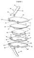
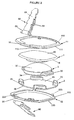
- the intervertebral disc prosthesis according to the present invention is constituted in an upper plate (1) articulated in relation to a lower plate (2) by means of a core (3) and each of the plates (1, 2) is equipped with an anatomic adaptation element (11, 22) allowing to adjust the overall size of the prosthesis to the size of the vertebrae between which the prosthesis is intended to be inserted.
- anatomic adaptation element 11, 22
- a single unit constitutes two plates (1, 2) and the core (3) can be used for different sizes of vertebrae, which has the advantage of substantially reducing the cost of manufacturing prostheses and their variances.
- the advantage of the prosthesis according to the invention is that it comprises simple parts whose anatomic adaptation elements (11, 22) can be sized so as to adapt to different vertebrae of the spinal column, for example, the adjust the thickness of the prosthesis to the intervertebral gap and/or adjust the inclination of the plates (1, 2) of the prosthesis to the inclination of the vertebrae of the patient.
- the anatomic adaptation elements (11, 22) allow themselves to adjust the prosthesis to different sizes of vertebrae , the plates (1, 2) and the core (3) of differing sizes and shapes can naturally be used if needs be.
- the two anatomic adaptation elements (11, 22) of the prosthesis according to the invention consist in an upper element (11) and a lower element (12).
- the upper element (11) has, on one hand, an upper surface (110) of which at least a part presents a surface in contact with a lower surface of a first vertebra and has, on the other hand, a lower surface (111) of which at least a part presents a surface in contact with a part of the upper plate (1).
- the lower element (22) has, on one hand, a lower surface (220) of which at least a part presents a surface in contact with an upper surface of a second vertebra and has, on the other hand, an upper surface (222) of which at least a part presents a surface in contact with a part of the lower plate (2).
- Each of the two anatomic adaptation elements (11, 22) is fixed onto the plates (1, 2) via respective fixation means (113, 223).
- the core (3) is of slight thickness (from 3 to 15 mm, depending on the vertebrae between which the prosthesis is to be inserted).
- the core (3) could, for example, be made of polyethylene, a compressible material simulating the physical properties of elasticity of natural intervertebral discs.
- the core (3) has a convex part on at least a part of at least one of its upper (30) and lower (34) surfaces.
- it is the upper surface (30) of the core (3) which is convex and complementary with a concave part (140) of the lower surface (14) of the upper plate (1)
- the lower surface (34) of the core (3) is plane and complementary with at least a plane part of the upper surface (24) of the lower plate (2).
- the concave part (140) of the lower surface (14) of the upper plate (1) as particularly visible in figures 4A, 4B , 5A, 5B and 5C , has a circular periphery.
- the core (3) it is a part of the lower surface (34) of the core (3) that can be convex and complementary with a concave part of the upper surface (24) of the lower plate (2), whereas the upper surface (30) of the core (3) is plane and complementary with at least a plane part of the lower surface (14) of the upper plate (1).
- the concave surface lies on a part of one of the upper (30) and lower (34) surfaces of the core (3) and co-operates with a convex surface which lies on a part of a surface of one of the plates (1, 2).
- the non convex or non concave surface of the core (3) can respectively be concave or convex, for example very slightly.
- the concave part (140) of the lower surface (14) of the upper plate (1) complementary with the convex part of the upper surface (34) of the core (3) allows to incline the upper plate (1) when the patient wearing the prosthesis bends over.
- the co-operation between the concave surface (140) and the convex surface (34) presents a surface of articulation with the prosthesis, thanks to this inclination of the upper plate (1) in relation to the core (3).
- the centre of this articulation is naturally at the tip of the convex surface (34) of the core (3).
- the lower surface of the core (3) and the upper surface of the lower plate (2) are plane so as to permit clearance of the core (3) in relation to the lower plate (2), both in translation according to an axis substantially parallel to the lower plate (2), and in rotation about an axis substantially perpendicular to the lower plate (2).
- this inclination of the upper plate (1) and this clearance of the core will allow displacement of the core (3) towards the ideal position to absorb the constraints applied to the prosthesis.
- the movement between the upper plate (1) and the core (3), as well as the clearance of the core (3) in relation to the lower plate (2) thus allow the patient to move, and, optionally, to eliminate the defects of positioning the prosthesis.
- This clearance likewise has the advantage of preventing premature wear due to the constraints applied to the prosthesis.
- the core (3) also has male or female co-operation means (33) complementary with respectively female or male co-operation means (23) present on at least one of the plates (1, 2).
- each male co-operation means (33) can be slightly less than those of each female co-operation means (23) so as to allow slight clearance between the core (3) and the plate (1, 2) equipped with these co-operation means.
- the dimensions of each male cooperation means (33) can also be substantially the same as those of each female co-operation means (23) so as to prevent any clearance between the core (3) and the plate (1, 2) equipped with these co-operation means.
- the core (3) has male co-operation means (33) complementary with female co-operation means (23) present on the lower plate (2).
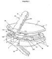
- the male co-operation means (33) of the core (3) are, for example, hasps or blocks substantially parallelepiped in shape, present on the side edges of the core (3), as particularly visible in figures 1 to 3 .
- the female co-operation means (23) can consist, for example, in four walls situated, in pairs, on each of the two side edges of the lower plate (2). These walls could be curved to the centre of the prosthesis, so as to cover at least a part of the male co-operation means (33) of the core (3) and avoid lifting the core (3) and the upper plate (1).
- each male co-operation means (33) of the core (3) are substantially the same as those of each female co-operation means (23) of the lower plate (2), so as to avoid any clearance of the core (3) in relation to the lower plate (2), both in translation and in rotation. In the latter case, the only permitted movement of the prosthesis is the inclining of the upper plate (1) in relation to the core (3).
- the core (3) has female co-operation means, consisting, for example, in complementary recesses of the male means present on the lower plate (2).
- These male means of the lower plate (2) can consist, for example, in two blocks or two nibs, for example curved to the interior of the prosthesis and facing one another on two edges of the lower plate (2).
- the nibs can, for example, be replaced by a block with a bore on which is fixed a hasp by way of a pin penetrating the bore.
- the lower plate (2) has half dog points.
- the core (3) by way of complement, has wells under its lower surface. The dimensions of the half dog points of the lower plate (2) and of the wells of the core (3) will be adapted, by choice, by a slight clearance of the core (3) in translation and in rotation or by no clearance, according to the desired result.
- the co-operation means can be located on the core (3) and on the upper plate (1), instead of the lower plate (2).
- the upper (11) and lower (12) anatomic adaptation elements consist in plates, called anatomic, which respectively cover the upper (1) and lower (2) plates.
- the upper (222) and lower (111) surfaces of respectively the lower (22) and upper (11) anatomic adaptation elements can have a reinforcement in which respectively the lower (2) and upper (1) plates are housed.
- these upper (222) and lower (111) surfaces of the anatomic adaptation elements can be plane and comprise stoppers which, as for the aforementioned reinforcements, prevent respectively the lower (2) and upper (1) plates from moving in relation to the anatomic adaptation elements.
- the upper (222) and lower (111) surfaces of respectively the lower (22) and upper (11) anatomic adaptation elements prolong respectively the upper (10) and lower (20) surfaces of the upper (1) and lower (2) plates, to present contact surfaces of the prosthesis with the adjacent vertebrae which are bigger than when there are no anatomic adaptation elements (11, 22).
- Different sizes of the anatomic plates of the anatomic adaptation elements (11, 22) can be adapted to a single unit created by the two plates (1, 2) and the core (3), to provide good contact between the prosthesis and the vertebrae of differing sizes.
- the anatomic adaptation elements (11, 22) consist in crowns which surround the upper (1) and lower (2) plates.
- the edges of the upper (10) and lower (20) surfaces of respectively the upper (1) and lower (2) plates are bevelled and complementary with respectively the lower (111) and upper (222) inside edges of respectively the upper (11) and lower (22) crowns.
- This inclined shape of the edges of the plates (1, 2) and of the anatomic adaptation crowns (11, 22) co-operates with the fixation means (113, 223) of the anatomic adaptation elements in order to maintain the anatomic adaptation crowns (11, 22) fixed in plane of respectively the upper (1) and lower (2) plates of the prosthesis.
- the anatomic adaptation crowns (11, 22) prolong respectively the upper (10) and lower (20) surfaces of respectively the upper (1) and lower (2) plates, to present contact surfaces of the prosthesis with the adjacent vertebrae which are bigger than when there are no anatomic adaptation elements (11, 22).
- a single unit created by the two plates (1, 2) and the core (3) can thus be adjusted to vertebrae of differing sizes, thanks to different sizes of crowns of the anatomic adaptation elements (11, 22).
- the anatomic adaptation elements (11, 22) can symmetrically or asymmetrically prolong the upper (10) and lower (20) surfaces of respectively the upper (1) and lower (2) plates.
- the anterior edge of the anatomic adaptation elements (11, 22) can have a bigger contact surface with the vertebrae than its posterior edge, so that the centre of articulation of the prosthesis (described above) is centred in relation to the natural axis of the spinal column, that meaning off centre to the rear of the vertebrae of a 2/3-1/3 section.
- the intervertebral disc prosthesis according to the invention allows, for example, to correct the defects of lordosis.
- the presence of an angle between the upper and lower surfaces of the prosthesis, in contact with the adjacent vertebrae, could be desirable.
- Such an angle could be obtained by making an upper plate (1), whose median planes representing its lower (14) and upper (10) surfaces create an angle.
- Another possibility consists in that it is the lower plate (2) whose median planes representing its lower (20) and upper (24) surfaces create an angle.
- Another possibility consists in that it is at least one of the anatomic adaptation elements (11, 22) whose median planes representing its lower and upper surfaces create an angle.
- a single unit made of the two plates (1, 2) and the core (3) can be used, for example, to induce or not lordosis, depending on which anatomic adaptation elements (11, 22) are associated to it.
- the lower surface (220) of the lower anatomic plate (22) creates an angle with its upper surface (222).
- Another possibility to obtain such an angle consists in a slightly offset position of the core (3) in relation to the centre of the prosthesis.
- This slightly offset position of the core (3) can, for example, be maintained thanks to an adjustable positioning of the male and female co-operation means (23, 33) between themselves.
- the surgeon wishes, for example, that the prosthesis induces lordosis which remains within a range of values, he will select a prosthesis whose core (3) can have slight clearance in translation and in rotation in relation to the lower plate (2), but about a position imposing a slight permanent inclination of at least one of the plates, thanks to an accurate adjustment of the co-operation means (23, 33) between the core (3) and the lower plate (2).
- the median planes representing the upper (110, 222) and lower (111, 220) surfaces of each of the anatomic adaptation elements (11, 22) can be substantially parallel or form an acute angle.
- the inclination obtained by such an angle allows to adapt the overall shape of the prosthesis to the anatomy of the spinal column or to possibly correct inclination defects of the vertebrae of the patient for whom the prosthesis is intended.
- the same anatomic adaptation elements (11, 22) can be assembled with different plates (1, 2) whose upper (10, 24) and lower (14, 20) surfaces create different angles.
- the plates (1, 2), whose upper (10, 24) and lower (14, 20) surfaces are parallel, are assembled with the anatomic adaptation elements (11, 22) whose upper (110, 222) and lower (111, 220) surfaces create different angles.
- This angle between the upper (10) surface of the upper plate (1) and the lower surface (20) of the lower plate (2) can be imposed either by the fact that the median planes representing the lower (20, 14) and upper (24, 10) surfaces of the lower plate (2) and/or the upper plate (1) create an angle, or by restricting, thanks to the co-operation means (23, 33), movements of the core (3) about a position imposing an inclination of at least one of the plates (1, 2).
- these osseous anchorage means (60) can be fixed onto the anatomic adaptation elements (11, 22) upon fixing them onto the plates (1, 2) and most of all upon inserting the prosthesis between the vertebrae. This feature allows the surgeon to easily position the prosthesis between the vertebrae and then insert the osseous anchorage means (60) once the prosthesis has been correctly positioned.
- these movable osseous anchorage means (60) consist in a plate (61) equipped with notches (62) oriented to resist against the removal of the plate (61) once it has been inserted into the vertebra.
- This plate (61) can, of course, be replaced by a rod in the shape of a nail, for example, with or without notches (62) to resist against its removal from the vertebra.
- a far end of the plate (61) bears a part (63) curved to fold over itself.
- This curved part forms a kind of a hook intended to be interlocked onto an edge (16, 26) of an opening made in the vicinity of the periphery of the anatomic adaptation elements (11, 22).
- This edge (16, 26) of the opening creates a sort of rod onto which the osseous anchorage means (60) interlock.
- the curved part (63) allows clasping the osseous anchorage means (60) onto the rod (16, 26) of the anatomic adaptation elements (11, 22).
- the rod (16, 26) is located on the anterior edge of the anatomic adaptation elements (11, 22) so as to allow the surgeon access once the prosthesis has been inserted between the vertebrae via anterior means (through accessing the vertebrae from their anterior face). If the implanting of the prosthesis is to be done via posterior means, the anatomic adaptation elements (11, 22) could have a rod (16, 26) located on the posterior edge. If the implanting of the prosthesis is to be done via lateral means, the anatomic adaptation elements (11, 22) could have a rod (16, 26) located on at least one of their edges.
- the hooked part (63), curved to fold over itself, of the notched plate (61) of the movable osseous anchorage means (60) of the anatomic adaptation elements (11, 22) prolong with a second plate (61) also equipped with notches (62) oriented to resist against the removal of the plate (61) once it has been inserted into the vertebra.
- this second plate (61) is shorter than the first plate and in the embodiment illustrated in figure 3 , it is as long as the first plate.
- the fact that the osseous anchorage means (60) locks onto the rod (16, 26) allows it to have a variable angle which facilitates the attaching of the prosthesis.
- the surgeon will have a choice of angles according to which he wishes to drive the osseous anchorage means (60) into the vertebrae.
- the fact that the osseous anchorage means (60) can be inserted after positioning the prosthesis between the vertebrae this allows to adjust the relative position of the different elements (1, 2, 3) of the prosthesis.
- the inserting of the prosthesis generates constraints on the elements of the prosthesis which are movable in relation to each other and they risk being badly position together.
- the surgeon can then, thanks to the invention, adjust the position of the prosthesis between the vertebrae and adjust the relative position of the elements of the prosthesis between themselves prior to definitively attaching the prosthesis.
- the present prosthesis can comprise other osseous anchorage means (60) than those described above, without departing from the scope of the present invention.
- such osseous anchorage means (60) can consist of winglets fixed on the prosthesis as in the Patent Application WO03/039400 or of a stud nailed in the vertebra through the anatomic adaptation elements as in the Patent Application WO04/041129 .
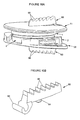
- One embodiment of the anchorage means (60) is presented on the figures 10A, 10B , 11A and 11B .
- the osseous anchorage means (60) according to this embodiment consist of winglets comprising a hooked part (63), curved to fold over itself, so that the winglets can be adapted onto the anatomic adaptation elements.
- the hooked part (63) of the winglet allows the anchorage means (60) to be interlocked onto the edge (16, 26) of an opening made in the vicinity of the periphery of the anatomic adaptation elements (11, 22), as particularly visible on figures 11A and 11B .
- This edge (16, 26) of the opening creates a sort of rod onto which the osseous anchorage means (60) interlock, as described above.
- the winglet further comprises a pin (64) (or a dowel) adapted to be inserted into a groove (65) present on the surface of the plate and/or the anatomic adaptation element on which the winglet is to be fixed, as particularly visible on figure 11 B .
- the groove (65) and the pin (64) have dimensions adapted so that the pin (64) is secured into groove (65).
- the pin (64) may have a substantially conical shape, with the larger diameter of the cone being at the base of the pin and the smaller diameter being at its end.
- the groove (65) may have its side walls adapted to cooperate with the conical shape of the pin (64) so that the pin tightly fits inside the groove and thus secures the osseous anchoring means (60) onto the anatomic adaptation elements (11, 22).
- the width of the groove (65) may be larger at its surface than at its bottom.
- the osseous anchorage means (60) are thus fixed onto the prosthesis of the present invention by first interlocking the hooked part (63) onto the rod (16, 26) of the anatomic adaptation elements (11, 22) and by rotating the osseous anchorage means (60) around the rod until the pin (64) penetrates tightly into the groove (65) of the anatomic adaptation element (11, 22) and/or of the plate (1, 2).
- the winglet (60) can have a standard size for all the prosthesis made according to the present invention and the position of the pin (64) of the winglet (60) inside the groove (65) will vary as a function of the size of the anatomic adaptation elements (11, 22).
- the pin (64) penetrates into the anatomic adaptation element (11, 22) only or may traverse the anatomic adaptation element (11, 22) and penetrate into a groove (65) in the plates (1, 2), as shown for example on figure 11B for the upper plate (1).
- their groove may have variable lengths and can be replaced by a hole having a variable distance from the rod (16, 26) so that the hole is adapted to receive the pin (64), but when the pin is designed to penetrate the plates also, the plates will have to include a groove because the distance of the pin from the periphery of the plates will vary depending on the size of the anatomic adaptation element (11, 22).
- the winglets (60) are adapted to cooperate with a groove drilled in the surfaces of the adjacent vertebrae with which they are in contact.
- the surgeon may perform a groove in the surfaces of vertebrae between which the prosthesis is intended to be inserted.
- This groove in the vertebrae will naturally have an orientation relative to the sagittal plane that will depend on the position and orientation of the winglet. This orientation will be predetermined and will set and secure the orientation of the prosthesis.
- the depth of the groove in the vertebrae and its extend from the periphery will be predetermined as a function of the size of the winglet (60) and will allow the surgeon to adjust the relative position of the various elements of the prosthesis and to predict the position of the prosthesis relative to the natural axis of the vertebrae.
- the winglets comprise notches (66) on their surfaces which are intended to be in contact with the bottom of the groove performed in the vertebrae. These notches (66) of the winglets (60) will resist against the ejection of the prosthesis from inside its housing between the vertebrae, for example when strong constraints are applied to the prosthesis.
- the hooked part (63) of the winglets (60) can be oriented so that they are to be interlocked onto the rod (16, 26) by being inserted inside the opening made in the vicinity of the periphery of the anatomic adaptation elements (11, 22) or by being inserted from outside this opening.
- the osseous anchoring means (60) described above are particularly adapted to the anatomic adaptation elements (11, 22) of the present invention but may also be adapted to the plates of other types of intervertebral disc prosthesis having plates comprising an opening in the vicinity of their periphery.
- the edge (16, 26) of such opening in the plates create a sort of rod (16, 26) onto which the hooked part (63) of both removable embodiments of the osseous anchoring means (60) can be interlocked.
- FIGs 4 to 9 illustrate the plates (1, 2) of the prosthesis traverse equipped with their anatomic adaptation elements (11, 22) and define different embodiments of the fixation means (113, 223, 15, 25) of these anatomic adaptation elements (11, 22) on the plates (1, 2).
- fixation means (113, 223, 15, 25) are reversible, this means that the anatomic adaptation elements (11, 22) can be easily attached and removed from the plates (1, 2) of the prosthesis.
- These fixation means (113, 223, 15, 25) allow the anatomic adaptation elements (11, 22), fixed in a moveable manner to the plates (1, 2), to be changed.
- the fixation means (113, 223, 15, 25) of the anatomic adaptation elements (11, 22) on the plates (1, 2) consist in fixation means (113, 223) present on the anatomic adaptation elements (11, 22) and complementary with the fixation means (15, 25) present on the plates (1, 2) of the prosthesis.
- the anatomic adaptation elements (11, 22) are fixed onto the plates (1, 2) via, on one hand, contact of at least a part of their lower (111) and upper (222) surface with at least a part of respectively the upper (1) and lower (2) plates and, on the other hand, contact of their fixation means (113, 223) with the complementary fixation means (15, 25) present on the plates (1, 2) of the prosthesis.
- the anatomic adaptation elements (11, 22) are fixed onto the plates (1, 2) thanks to the fact that the upper (10) and lower (20) surfaces of respectively the upper (1) and lower (2) plates are firmly attached to the reinforcements present on the lower (111) and upper (222) surfaces of respectively the upper (11) and lower (22) anatomic plates, via the fixation means (113, 223, 15, 25).
- the anatomic adaptation elements (11, 22) are fixed onto the plates (1, 2) thanks to the fact that the bevelled parts of the upper (10) and lower (20) surfaces of respectively the upper (1) and lower (2) plates are firmly attached to the bevelled parts of the upper (111) and lower (222) surfaces of respectively the upper (11) and lower (22) anatomic plates, via the fixation means (113, 223, 15, 25).
- the different embodiments of the fixation means (113, 223, 15, 25) of the anatomic adaptation elements (11, 22) on the plates (1, 2) will now be described in reference to figures 4 to 9 . It is obvious that these fixation means are given by way of illustration and can be replaced by any equivalent means without leaving the scope of the invention. Likewise, the invention allows the use of any whatsoever combination of the different fixation means (113, 223, 15, 25) described below.
- the fixation means (113, 223, 15, 25) of the anatomic adaptation elements (11, 22) on the plates (1, 2) consist in male fixation means (113, 223) present on the anatomic adaptation elements (11, 22) and co-operate with the female fixation means (15, 25) present on the plates (1, 2) of the prosthesis.
- the female fixation means (15, 25) present on the plates (1, 2) of the prosthesis can consist, for example, in plane surfaces (15, 25) present on the edges of the plates (1, 2) of the prosthesis or in recesses (15, 25) either made in the edges of the plates (1, 2) of the prosthesis, or in the edges of the female co-operation means (23) of the plates (1, 2) of the prosthesis.
- the fixation means (113) of the upper anatomic plate (11) consist, on the posterior edge of its lower surface (111), in nibs which are shaped and have dimensions intended to receive a section (15) of the posterior edge of the lower surface (14) of the upper plate (1).
- the fixation means (113) of the upper anatomic plate (11) consist in latches constituted in an axis of rotation onto which a hasp is mounted intended to swivel about this axis and receive a section (15) of the posterior edge of the lower surface (14) of the upper plate (1), as particularly visible in figures 4A and 4B .
- the fixation means (223) of the lower anatomic plate (22) consist, on the posterior edge of its lower surface (222), in nibs which are shaped and have dimensions intended to fit into an opening (25) made in the co-operation means (23) of the lower plate (2).
- the fixation means (223) of the upper anatomic plate (22) consist in latches constituted in an axis of rotation onto which a hasp is mounted intended to receive a recess (25) made in a part of the co-operation means (23) present on the posterior edge of the lower plate (2).
- the latches illustrated in figures 4A to 4D can be maintained in the closed position via securing means (55) present, for example, on the plates (1, 2) of the prosthesis.
- securing means (55) present, for example, on the plates (1, 2) of the prosthesis.
- a notch (55) made on the recess (25) present on a part of the co-operation means (23) of the lower plate (2) prevents the latch (223) of the lower anatomic plate (22) from swivelling.
- the anterior and posterior edges of the upper anatomic adaptation crowns (11) have fixation means (113) consisting in nibs which co-operate with a plane section (15) present on the edge of the lower surface (14) of the upper plate.
- the fixation means (113, 223, 15, 25) of the anatomic adaptation elements (11, 22) on the plates (1, 2) consist in female fixation means (113, 223) present on the anatomic adaptation elements (11, 22) and co-operating with male intermediary means (50) which can also co-operate with the female fixation means (15, 25) present on the plates (1, 2) of the prosthesis.
- the anatomic adaptation elements (11, 22) are fixed onto the plates (1, 2) via, on one hand, contact of at least a part of their upper (111) and lower (222) surface with at least a part of respectively the upper (1) and lower (2) plates and, on the other hand, contact of the male intermediary means (50) with the female fixation means (113, 223) present on the anatomic adaptation elements (11, 22) and with the female fixation means (15, 25) present on the plates (1, 2) of the prosthesis.
- the male intermediary means (50) consist in a sliding plate (50) in the female fixation means (113, 223) present on the anatomic adaptation elements (11, 22) to co-operate with the female fixation means (15, 25) present on the plates (1, 2) of the prosthesis.
- the plate (50) is substantially parallelepiped in shape and can comprise, on its side edges, fins (500), particularly visible, for example, in figure 7A .
- These fins (500) of the male intermediary means (50) are of complementary shape with the female fixation means (113, 223) of the anatomic adaptation elements (11, 22) and with the female fixation means (15, 25) of the plates (1, 2) of the prosthesis, which have side runners in which these fins (500) slide.
- the male intermediary means (50) have securing means (55) blocking the male intermediary means (50) in the position where they co-operate with both the female fixation means (113, 223) of the anatomic adaptation elements (11, 22) and with the female fixation means (15, 25) present on the plates (1, 2) of the prosthesis.
- These securing means (55) which consist, for example, in at least a formal irregularity (55) present on at least one side of this plate (50) and intended to co-operate with at least an opening (550) made in the female fixation means (113, 223) of the anatomic adaptation elements (11, 22) and/or in the female fixation means (15, 25) of the plates (1, 2).
- the opening (550) can be of a complementary shape of the male intermediary means (50) or of its securing means, as illustrated in figures 6A and 6B .
- the plate constituting the male intermediary means (50) widens out towards its posterior end and the formal irregularity constituting the securing means (55) consists in a slot on the posterior half of the plate (50). This slot (55) compresses the posterior end of the plate (50) when it is introduced into the female fixation means (113, 223) of the upper and/or lower anatomic adaptation elements (11, 22), as illustrated for the left-hand plate in figure 6A .
- FIG. 7B illustrates a perspective view of this embodiment of the fixation means in which the plate (50) is intended to be held in the female manes (25) made in the co-operation means (23) of the lower plate (2).
- This figure also notably shows the fact that the reinforcement present, for example, on the lower anatomic plate (22) can be deeper than the thickness of the lower plate (2).
- the edges of this reinforcement will provide a periphery abutment possibly limiting the displacement of the core (3) in relation to the lower plate (2).
- the formal irregularities constituting the securing means (55) of the male intermediary means (50) consist in hasps present on the side edges of the plate (50). As illustrated for the left-hand plate (50) in figure 6B , these hasps (55) are compressed when the hasp is introduced into the runners of the female means (113, 223).
- the hasps (55) naturally open out in the openings (550) provided for on the side edges of the female means (113, 223) of the upper and/or lower anatomic adaptation elements (11, 22), as illustrated for the right-hand plate (50) in figure 6B .
- Figures 7A and 8A to 8D illustrate another alternative embodiment of the male intermediary means (50).
- the formal irregularities of the plate (50) constituting the securing means (55) of the plate (50) consist in a bore in the male intermediary means (50), prolonged by a bore (550) in the female fixation means (113, 223) of the anatomic adaptation elements (11, 22), as particularly visible in figure 8B .
- the bore (550) is intended to receive a securing pin (55) blocking the male intermediary means (50) in the position where they co-operate with the female fixation means (15, 25) present on the plates (1, 2) of the prosthesis, as illustrated in figure 8C .
- FIG. 9A Another alternative of the securing means (55) of the male intermediary means (50) is illustrated in figures 9A to 9D .
- the formal irregularities constituting the securing means (55) of the plate (50) consist in a notch (55) present on the lower surface of the plate and intended to co-operate with an opening (550) made in the female fixation means (113, 223) of the anatomic adaptation elements by resisting against the removal of the plate (50), once driven as far as the female fixation means (15, 25) of the plates (1, 2), as illustrated in figure 9D .
Landscapes
- Health & Medical Sciences (AREA)
- Engineering & Computer Science (AREA)
- Biomedical Technology (AREA)
- Orthopedic Medicine & Surgery (AREA)
- Life Sciences & Earth Sciences (AREA)
- Veterinary Medicine (AREA)
- Public Health (AREA)
- General Health & Medical Sciences (AREA)
- Heart & Thoracic Surgery (AREA)
- Animal Behavior & Ethology (AREA)
- Cardiology (AREA)
- Vascular Medicine (AREA)
- Transplantation (AREA)
- Oral & Maxillofacial Surgery (AREA)
- Neurology (AREA)
- Surgery (AREA)
- Rheumatology (AREA)
- Nuclear Medicine, Radiotherapy & Molecular Imaging (AREA)
- Medical Informatics (AREA)
- Molecular Biology (AREA)
- Prostheses (AREA)
Description
- The present invention relates to an intervertebral disc prosthesis, intended to be substituted for fibro-cartilaginous discs ensuring a bond between the vertebrae of the spinal column.
- Various types of intervertebral disc prostheses are known in the prior art. Numerous prostheses, such as for example in the patent application
WO 02 089 701 WO 2004/041129 , are constituted in a lower plate and an upper plate forming a sort of cage around a central core. A part of these prostheses enables the upper plate to swivel in relation to the central core and optionally permits the central core to slide in relation to the lower plate. This sliding of the central core in relation to the lower plate is an essential characteristic, as it must allow spontaneous positioning of the core in the ideal position to absorb constraints imposed on the prosthesis, during movements made by the patient wearing the prosthesis. The displacement of the core, co-operating with at least a plate about an uneven surface, enables an inclination between the plates of the prosthesis which facilitates the mobility of the patient wearing the prosthesis. The displacement of the core also prevents it from creeping under load, when subjected to major constraints. A part of these prostheses have osseous anchorage means allowing to attach these prostheses to the vertebrae between which they are intended to be inserted. - However, the size of the vertebrae varies greatly from person to person, for a same vertebra in a given position in the spinal column, but also for a given person depending on the position of the vertebrae in the spinal column between which a prosthesis is intended to be inserted. The intervertebral disc prostheses must be of a suitable size for the vertebrae between which they are intended to be inserted, depending on the person and on the position of these vertebrae in the spinal column. Moreover, depending on the spinal column disorder of the patient wearing the prosthesis, it is sometimes preferable that the prosthesis allows a correction of this disorder. The prostheses can thus be used to correct an inclination defect of the vertebrae, such as, for example, lordosis. It is known from prior art, in particular from Patent Applications
WO 2004/034935 andDE 203 20 454 comprising at least two plates and at least one core, wherein the size of the plate can vary to be adapted to the size of the vertebrae between which the prosthesis is intended to be implanted. Patent ApplicationsWO 2004/034935 also describes convex surfaces, chamfers or rounding on the surface of the plates contacting the vertebrae, for a good contact between the prosthesis and the surfaces of the vertebral bodies. To have prostheses that are suitable for the as big a majority of cases as possible, a large number of prostheses with different plate sizes and inclinations must therefore be envisaged. This multiplicity of prostheses has the major inconvenience of high manufacturing costs and high stock levels. In this context, it is beneficial to propose a prosthesis that has a structure allowing it to be adapted to different sizes of vertebrae and allowing for different inclinations of the plates. Such a prosthesis would reduce stock levels and manufacturing costs. - The aim of the present invention is to propose an intervertebral disc prosthesis allowing limited movements of the different pieces of the prosthesis between one another and comprising a core used to restrict its displacement in at least one direction. A same prosthesis can be adapted to different sizes of vertebrae at reduced costs.
- This aim is achieved by an intervertebral disc prosthesis comprising at least three pieces including an upper plate, a lower plate, and a movable core at least in relation to a plate, having the characterising features of
claim 1. - According to another feature, the anatomic adaptation elements consist in crowns which surround the plates and prolong respectively their upper and lower surfaces to present contact surfaces of the prosthesis with the adjacent vertebrae which are bigger than when there are no anatomic adaptation elements.
- According to another feature, the anatomic adaptation elements symmetrically prolong the upper and lower surfaces of respectively the upper and lower plates to present an equivalent prolongation of these surfaces on the different anterior, posterior and lateral edges of the plates.
- According to another feature, the anatomic adaptation elements asymmetrically prolong the upper and lower surfaces of respectively the upper and lower plates to present a bigger prolongation of these surfaces on at least one of the anterior, posterior and lateral edges of the plates than on the other edges.
- According to another feature, the upper surface of the core is in contact with at least one part of the lower surface of the upper plate and the lower surface of the core is in contact with at least one part of the upper surface of the lower plate.
- According to another feature, at least one part of the surface of at least a plate is concave and complementary with a convex surface of the core with which it is in contact.
- According to another feature, at least one part of the surface of at least a plate is plane and complementary with a plane surface of the core with which it is in contact.
- According to another feature, male and female co-operation means situated in the vicinity of the edges of at least one plate and the core limiting, without excessive friction, the movements in translation of the core relative to this plate, according to an axis substantially parallel to this plate, and limiting or suppressing the movements in rotation of the core relative to this plate, about an axis substantially perpendicular to this plate.
- According to another feature, the dimensions of each male co-operation means are slightly less than those of each female co-operation means so as to allow slight clearance between the core and the plate equipped with these co-operation means.
- According to another feature, the dimensions of each male co-operation means are substantially the same as those of each female co-operation means so as to prevent any clearance between the core and the plate equipped with these co-operation means.
- According to another feature, the co-operation means of the plate are female co-operation means co-operating with male co-operation means of the core.
- According to another feature, the male co-operation means of the core are two blocks situated on the two side edges of the core and the female co-operation means of the plate are four walls situated, in pairs, on each of the two side edges of this plate.
- According to another feature, the fixation means of the anatomic adaptation elements on the plates of the prosthesis are reversible and allow changing the anatomic adaptation elements fixed in a movable manner onto the plates of the prosthesis.
- According to another feature, the fixation means of the anatomic adaptation elements on the plates consist in fixation means present on the anatomic adaptation elements and complementary with fixation means present on the plates of the prosthesis.
- According to another feature, the anatomic adaptation elements are fixed onto the plates via, on one hand, contact with at least a part of their surfaces which face at least a part of the plates and, on the other hand, contact of their fixation means with the complementary fixation means present on the plates of the prosthesis.
- According to another feature, the fixation means of the anatomic adaptation elements on the plates consist in male fixation means present on the anatomic adaptation elements and co-operating with the female fixation means present on the plates of the prosthesis or inversely.
- According to another feature, the female fixation means present on the plates of the prosthesis consist in plane surfaces present on the edges of the plates of the prosthesis.
- According to another feature, the female fixation means present on the plates of the prosthesis consist in recesses made in the edges of the other plate of the prosthesis.
- According to another feature, the female fixation means present on the plates of the prosthesis consist in recesses made in the edges of the female co-operation means of the plates of the prosthesis.
- According to another feature, the female fixation means present on the plates of the prosthesis consist in plane surfaces present on the edges of one of the plates and in recesses made in the female co-operation means of the edges of the other plate of the prosthesis.
- According to another feature, the female fixation means present on at least one of the plates of the prosthesis consist in plane surfaces present on at least a first edge of one of the plates and in recesses made in at least a second edge of the plate of the prosthesis, the second edge geometrically facing a first edge of the plate.
- According to another feature, at least one of the female fixation means present on the plates of the prosthesis comprises at least a notch allowing blocking the male fixation means of the anatomic adaptation elements on this female fixation means.
- According to another feature, the fixation means of the anatomic adaptation elements on the plates consist in female fixation means present on the anatomic adaptation elements and co-operating with male intermediary means which can also co-operate with the female fixation means present on the plates of the prosthesis.
- According to another feature, the anatomic adaptation elements are fixed onto the plates via, on one hand, contact of at least a part of their upper and lower surface with at least a part of respectively the upper and lower plates and, on the other hand, contact of the male intermediary means with the female fixation means present on the anatomic adaptation elements and with the female fixation means present on the plates of the prosthesis.
- According to another feature, the male intermediary means possess securing means blocking the male intermediary means in the position where they co-operate with both the female fixation means of the anatomic adaptation elements and with the female fixation means present on the plates of the prosthesis.
- According to another feature, the male intermediary means consist in a sliding plate in the female fixation means present on the anatomic adaptation elements to co-operate with the female fixation means present on the plates of the prosthesis, the securing means of the male intermediary means consisting in at least a formal irregularity present on at least one side of this plate and intended to co-operate with at least an opening made in the female fixation means of the anatomic adaptation elements and/or in the female fixation means of the plates, thus blocking the male intermediary means in the position where they co-operate with both the female fixation means of the anatomic adaptation elements and with the female fixation means present on the plates of the prosthesis.
- According to another feature, the securing means of the male intermediary means consist in a bore in the male intermediary means and in the female fixation means present on the anatomic adaptation elements, the bore in the female fixation means of the anatomic adaptation elements being intended to receive a securing pin blocking the male intermediary means in the position where they co-operate with the female fixation means present on the plates of the prosthesis.
- According to another feature, the median planes representing the upper and lower surfaces of each of the anatomic adaptation elements are substantially parallel or form an acute angle, the inclination obtained by such an angle allowing to adapt the overall shape of the prosthesis to the anatomy of the spinal column or to possibly correct inclination defects of the vertebrae of the patient for whom the prosthesis is intended.
- According to another feature, the same anatomic adaptation elements are assembled with different plates whose upper and lower surfaces create different angles.
- According to another feature, an angle between the upper surface of the upper plate and the lower surface of the lower plate is imposed either by the fact that the median planes representing the upper and lower surfaces of the lower plate and/or the upper plate create an angle, or by restricting, thanks to the co-operation means, movements of the core about a position imposing an inclination of at least one of the plates.
- According to another feature, the same plates are assembled with cores of different thicknesses and/or sizes and/or shapes.
- According to another feature, the anatomic adaptation elements comprise movable osseous anchorage elements that are fixed onto the anatomic adaptation elements upon fixing the anatomic adaptation elements onto the plates, inserting the prosthesis between the vertebrae and possibly adjusting the relative position of the different elements of the prosthesis.
- According to another feature, the movable osseous anchorage elements of the anatomic adaptation elements consist in at least a plate equipped with notches oriented to resist against the removal of the plate once it has been inserted into a vertebra, a far end of the plate bearing a part curved to fold over itself and intended to be interlocked as a hook onto an edge of an opening made in the vicinity of the periphery of the anatomic adaptation elements.
- According to another feature, the part, curved to fold over itself, of the notched plate of the movable osseous anchorage means of the anatomic adaptation elements prolongs with a second plate also equipped with notches oriented to resist against the removal of the plate once it has been inserted into the vertebra.
- According to another feature, the anatomic adaptation elements comprise movable osseous anchorage elements consisting in at least one winglet to be inserted in a groove performed in the adjacent surfaces of the vertebrae between which the prosthesis is to be implanted, said winglet comprising notches oriented to resist against the ejection of the prosthesis outside its housing between the vertebrae, a far end of the winglet bearing a part curved to fold over itself and intended to be interlocked as a hook onto an edge of an opening made in the vicinity of the periphery of the anatomic adaptation elements.
- According to another feature, the winglet further comprises a pin having dimensions adapted so that it tightly fits into a groove of the anatomic adaptation elements and/or the plates.
- Other features and advantages of the invention will emerge more clearly from the description herein below, given in reference to the attached diagrams, in which:
-
figure 1 illustrates an exploded perspective view of the different elements of the prosthesis according to an embodiment of the invention, -
figure 2 illustrates an exploded perspective view of the different elements of the prosthesis according to another embodiment of the invention, -
figure 3 illustrates a perspective view of the prosthesis according to another embodiment of the invention. -
figures 4A and 4B respectively illustrate a bottom view and a cross section view along plane A-A infigure 4A , of the upper plate equipped with its anatomic adaptation element, according to an embodiment of the invention,figures 4C and 4D respectively illustrate a plan view and a cross section view along plane B-B infigure 4C , of the upper plate equipped with its anatomic adaptation element, according to an embodiment of the invention, -
figure 5A illustrates a bottom view of the upper plate equipped with its anatomic adaptation element, according to an embodiment of the invention, andfigures 5B and 5C illustrate cross section views respectively along plane C-C and plane D-D infigure 5A , of the upper plate equipped with its anatomic adaptation element, according to this embodiment of the invention, -
figures 6A and 6B illustrate bottom views of a part of the upper plate equipped with its anatomic adaptation element, according to two different embodiments of the invention, -
figures 7A and 7B illustrate perspective views of the lower plate equipped with its anatomic adaptation element, according to two different embodiments of the invention, -
figures 8A and 8B respectively illustrate a bottom view and a cross section view along plane E-E infigure 8A , of a part of the lower plate equipped with its anatomic adaptation element whose fixation means are open, according to an embodiment of the invention,figures 8C and 8D respectively illustrate a bottom view and a cross section view along plane F-F infigure 8C , of the same embodiment as infigures 8A and 8B , but with the fixation means of the anatomic adaptation element closed and locked, according to an embodiment of the invention, -
figures 9A and 9B respectively illustrate a bottom view and a cross section view along plane G-G infigure 9A , of a part of the lower plate equipped with its anatomic adaptation element whose fixation means are open, according to an embodiment of the invention,figures 9C and 9D respectively illustrate a bottom view and a cross section view along plane H-H infigure 9C , of the same embodiment as infigures 9A and 9B , but with the fixation means of the anatomic adaptation element closed and locked, according to an embodiment of the invention, -
figures 10A and 10B illustrate perspective views of, respectively, the prosthesis comprising osseous anchorage means according to an embodiment of the present invention and one of the osseous anchorage means according this embodiment, -
figures 11A and 11B respectively illustrate a perspective view of the prosthesis comprising osseous anchorage means according to an embodiment of the present invention and a cross section view along plane I-I offigure 11A . - The intervertebral disc prosthesis according to the present invention is constituted in an upper plate (1) articulated in relation to a lower plate (2) by means of a core (3) and each of the plates (1, 2) is equipped with an anatomic adaptation element (11, 22) allowing to adjust the overall size of the prosthesis to the size of the vertebrae between which the prosthesis is intended to be inserted. Thus, thanks to the anatomic adaptation elements (11, 22), a single unit constitutes two plates (1, 2) and the core (3) can be used for different sizes of vertebrae, which has the advantage of substantially reducing the cost of manufacturing prostheses and their variances. The advantage of the prosthesis according to the invention is that it comprises simple parts whose anatomic adaptation elements (11, 22) can be sized so as to adapt to different vertebrae of the spinal column, for example, the adjust the thickness of the prosthesis to the intervertebral gap and/or adjust the inclination of the plates (1, 2) of the prosthesis to the inclination of the vertebrae of the patient. Even though the anatomic adaptation elements (11, 22) allow themselves to adjust the prosthesis to different sizes of vertebrae , the plates (1, 2) and the core (3) of differing sizes and shapes can naturally be used if needs be.
- The two anatomic adaptation elements (11, 22) of the prosthesis according to the invention consist in an upper element (11) and a lower element (12). The upper element (11) has, on one hand, an upper surface (110) of which at least a part presents a surface in contact with a lower surface of a first vertebra and has, on the other hand, a lower surface (111) of which at least a part presents a surface in contact with a part of the upper plate (1). The lower element (22) has, on one hand, a lower surface (220) of which at least a part presents a surface in contact with an upper surface of a second vertebra and has, on the other hand, an upper surface (222) of which at least a part presents a surface in contact with a part of the lower plate (2). Each of the two anatomic adaptation elements (11, 22) is fixed onto the plates (1, 2) via respective fixation means (113, 223).
- The core (3) is of slight thickness (from 3 to 15 mm, depending on the vertebrae between which the prosthesis is to be inserted). For good absorption of the constraints, the core (3) could, for example, be made of polyethylene, a compressible material simulating the physical properties of elasticity of natural intervertebral discs.
- In all the possible embodiments of the invention, the core (3) has a convex part on at least a part of at least one of its upper (30) and lower (34) surfaces. In the embodiments illustrated in
figures 1 to 9 , it is the upper surface (30) of the core (3) which is convex and complementary with a concave part (140) of the lower surface (14) of the upper plate (1), whereas the lower surface (34) of the core (3) is plane and complementary with at least a plane part of the upper surface (24) of the lower plate (2). The concave part (140) of the lower surface (14) of the upper plate (1), as particularly visible infigures 4A, 4B ,5A, 5B and 5C , has a circular periphery. In other possible embodiments (not shown), it is a part of the lower surface (34) of the core (3) that can be convex and complementary with a concave part of the upper surface (24) of the lower plate (2), whereas the upper surface (30) of the core (3) is plane and complementary with at least a plane part of the lower surface (14) of the upper plate (1). In other embodiments (not shown), the concave surface lies on a part of one of the upper (30) and lower (34) surfaces of the core (3) and co-operates with a convex surface which lies on a part of a surface of one of the plates (1, 2). In these possible different embodiments (not shown) of the invention, the non convex or non concave surface of the core (3) can respectively be concave or convex, for example very slightly. - In the embodiments illustrated in
figures 1 to 9 , the concave part (140) of the lower surface (14) of the upper plate (1) complementary with the convex part of the upper surface (34) of the core (3) allows to incline the upper plate (1) when the patient wearing the prosthesis bends over. The co-operation between the concave surface (140) and the convex surface (34) presents a surface of articulation with the prosthesis, thanks to this inclination of the upper plate (1) in relation to the core (3). The centre of this articulation is naturally at the tip of the convex surface (34) of the core (3). In the illustrated embodiments, the lower surface of the core (3) and the upper surface of the lower plate (2) are plane so as to permit clearance of the core (3) in relation to the lower plate (2), both in translation according to an axis substantially parallel to the lower plate (2), and in rotation about an axis substantially perpendicular to the lower plate (2). During movements by the patient wearing the prosthesis, this inclination of the upper plate (1) and this clearance of the core will allow displacement of the core (3) towards the ideal position to absorb the constraints applied to the prosthesis. The movement between the upper plate (1) and the core (3), as well as the clearance of the core (3) in relation to the lower plate (2) thus allow the patient to move, and, optionally, to eliminate the defects of positioning the prosthesis. This clearance likewise has the advantage of preventing premature wear due to the constraints applied to the prosthesis. - Irrespective of the embodiment, the core (3) also has male or female co-operation means (33) complementary with respectively female or male co-operation means (23) present on at least one of the plates (1, 2). These male and female co-operation means (23, 33) situated in the vicinity of the edges of at least one plate (1, 2) and of the core (3) limit, without excessive friction, the movements in translation of the core (3) in relation to this plate (1, 2), according to an axis substantially parallel to this plate (1, 2), and limiting or suppressing the movements in rotation of the core (3) in relation to this plate (1, 2), about an axis substantially perpendicular to this plate (1, 2). The dimensions of each male co-operation means (33) can be slightly less than those of each female co-operation means (23) so as to allow slight clearance between the core (3) and the plate (1, 2) equipped with these co-operation means. On the contrary, the dimensions of each male cooperation means (33) can also be substantially the same as those of each female co-operation means (23) so as to prevent any clearance between the core (3) and the plate (1, 2) equipped with these co-operation means.
- In the embodiment in
figures 1 to 3 , the core (3) has male co-operation means (33) complementary with female co-operation means (23) present on the lower plate (2). The male co-operation means (33) of the core (3) are, for example, hasps or blocks substantially parallelepiped in shape, present on the side edges of the core (3), as particularly visible infigures 1 to 3 . The female co-operation means (23) can consist, for example, in four walls situated, in pairs, on each of the two side edges of the lower plate (2). These walls could be curved to the centre of the prosthesis, so as to cover at least a part of the male co-operation means (33) of the core (3) and avoid lifting the core (3) and the upper plate (1). These co-operation means (23, 33) also prevent the core (3) from ejecting out of the prosthesis, in the event of too much constraint on the prosthesis. In an alternative embodiment (not shown), the dimensions of each male co-operation means (33) of the core (3) are substantially the same as those of each female co-operation means (23) of the lower plate (2), so as to avoid any clearance of the core (3) in relation to the lower plate (2), both in translation and in rotation. In the latter case, the only permitted movement of the prosthesis is the inclining of the upper plate (1) in relation to the core (3). In an alternative embodiment (not shown), the core (3) has female co-operation means, consisting, for example, in complementary recesses of the male means present on the lower plate (2). These male means of the lower plate (2) can consist, for example, in two blocks or two nibs, for example curved to the interior of the prosthesis and facing one another on two edges of the lower plate (2). The nibs can, for example, be replaced by a block with a bore on which is fixed a hasp by way of a pin penetrating the bore. In another alternative embodiment (not shown), the lower plate (2) has half dog points. The core (3), by way of complement, has wells under its lower surface. The dimensions of the half dog points of the lower plate (2) and of the wells of the core (3) will be adapted, by choice, by a slight clearance of the core (3) in translation and in rotation or by no clearance, according to the desired result. In other alternatives (not shown), the co-operation means can be located on the core (3) and on the upper plate (1), instead of the lower plate (2). - The description of a first embodiment will now be considered in reference to
figure 1 . In this embodiment, the upper (11) and lower (12) anatomic adaptation elements consist in plates, called anatomic, which respectively cover the upper (1) and lower (2) plates. The upper (222) and lower (111) surfaces of respectively the lower (22) and upper (11) anatomic adaptation elements can have a reinforcement in which respectively the lower (2) and upper (1) plates are housed. In another alternative, these upper (222) and lower (111) surfaces of the anatomic adaptation elements can be plane and comprise stoppers which, as for the aforementioned reinforcements, prevent respectively the lower (2) and upper (1) plates from moving in relation to the anatomic adaptation elements. The upper (222) and lower (111) surfaces of respectively the lower (22) and upper (11) anatomic adaptation elements prolong respectively the upper (10) and lower (20) surfaces of the upper (1) and lower (2) plates, to present contact surfaces of the prosthesis with the adjacent vertebrae which are bigger than when there are no anatomic adaptation elements (11, 22). Different sizes of the anatomic plates of the anatomic adaptation elements (11, 22) can be adapted to a single unit created by the two plates (1, 2) and the core (3), to provide good contact between the prosthesis and the vertebrae of differing sizes. - In the embodiment of the prosthesis according to the invention illustrated in
figure 2 , the anatomic adaptation elements (11, 22) consist in crowns which surround the upper (1) and lower (2) plates. In this embodiment, the edges of the upper (10) and lower (20) surfaces of respectively the upper (1) and lower (2) plates are bevelled and complementary with respectively the lower (111) and upper (222) inside edges of respectively the upper (11) and lower (22) crowns. This inclined shape of the edges of the plates (1, 2) and of the anatomic adaptation crowns (11, 22) co-operates with the fixation means (113, 223) of the anatomic adaptation elements in order to maintain the anatomic adaptation crowns (11, 22) fixed in plane of respectively the upper (1) and lower (2) plates of the prosthesis. The anatomic adaptation crowns (11, 22) prolong respectively the upper (10) and lower (20) surfaces of respectively the upper (1) and lower (2) plates, to present contact surfaces of the prosthesis with the adjacent vertebrae which are bigger than when there are no anatomic adaptation elements (11, 22). In the same manner as for the aforementioned anatomic plates (11, 22), a single unit created by the two plates (1, 2) and the core (3) can thus be adjusted to vertebrae of differing sizes, thanks to different sizes of crowns of the anatomic adaptation elements (11, 22). - In all the embodiments of the invention, the anatomic adaptation elements (11, 22) can symmetrically or asymmetrically prolong the upper (10) and lower (20) surfaces of respectively the upper (1) and lower (2) plates. Thus, for example, the anterior edge of the anatomic adaptation elements (11, 22) can have a bigger contact surface with the vertebrae than its posterior edge, so that the centre of articulation of the prosthesis (described above) is centred in relation to the natural axis of the spinal column, that meaning off centre to the rear of the vertebrae of a 2/3-1/3 section.
- According to the chosen embodiments, the intervertebral disc prosthesis according to the invention allows, for example, to correct the defects of lordosis. The presence of an angle between the upper and lower surfaces of the prosthesis, in contact with the adjacent vertebrae, could be desirable. Such an angle could be obtained by making an upper plate (1), whose median planes representing its lower (14) and upper (10) surfaces create an angle. Another possibility consists in that it is the lower plate (2) whose median planes representing its lower (20) and upper (24) surfaces create an angle. Another possibility consists in that it is at least one of the anatomic adaptation elements (11, 22) whose median planes representing its lower and upper surfaces create an angle. Thus, a single unit made of the two plates (1, 2) and the core (3) can be used, for example, to induce or not lordosis, depending on which anatomic adaptation elements (11, 22) are associated to it. In the embodiment illustrated in
figure 3 , the lower surface (220) of the lower anatomic plate (22) creates an angle with its upper surface (222). Another possibility to obtain such an angle consists in a slightly offset position of the core (3) in relation to the centre of the prosthesis. This slightly offset position of the core (3) can, for example, be maintained thanks to an adjustable positioning of the male and female co-operation means (23, 33) between themselves. If the surgeon wishes, for example, that the prosthesis induces lordosis which remains within a range of values, he will select a prosthesis whose core (3) can have slight clearance in translation and in rotation in relation to the lower plate (2), but about a position imposing a slight permanent inclination of at least one of the plates, thanks to an accurate adjustment of the co-operation means (23, 33) between the core (3) and the lower plate (2). Thus, according to the chosen embodiment, the median planes representing the upper (110, 222) and lower (111, 220) surfaces of each of the anatomic adaptation elements (11, 22) can be substantially parallel or form an acute angle. The inclination obtained by such an angle allows to adapt the overall shape of the prosthesis to the anatomy of the spinal column or to possibly correct inclination defects of the vertebrae of the patient for whom the prosthesis is intended. The same anatomic adaptation elements (11, 22) can be assembled with different plates (1, 2) whose upper (10, 24) and lower (14, 20) surfaces create different angles. On the contrary, the plates (1, 2), whose upper (10, 24) and lower (14, 20) surfaces are parallel, are assembled with the anatomic adaptation elements (11, 22) whose upper (110, 222) and lower (111, 220) surfaces create different angles. This angle between the upper (10) surface of the upper plate (1) and the lower surface (20) of the lower plate (2) can be imposed either by the fact that the median planes representing the lower (20, 14) and upper (24, 10) surfaces of the lower plate (2) and/or the upper plate (1) create an angle, or by restricting, thanks to the co-operation means (23, 33), movements of the core (3) about a position imposing an inclination of at least one of the plates (1, 2). - Illustrated in
figures 1 to 3 are the movable osseous anchorage means (60) of the anatomic adaptation elements (11, 22). Advantageously, these osseous anchorage means (60) can be fixed onto the anatomic adaptation elements (11, 22) upon fixing them onto the plates (1, 2) and most of all upon inserting the prosthesis between the vertebrae. This feature allows the surgeon to easily position the prosthesis between the vertebrae and then insert the osseous anchorage means (60) once the prosthesis has been correctly positioned. In the embodiment presented infigure 1 , these movable osseous anchorage means (60) consist in a plate (61) equipped with notches (62) oriented to resist against the removal of the plate (61) once it has been inserted into the vertebra. This plate (61) can, of course, be replaced by a rod in the shape of a nail, for example, with or without notches (62) to resist against its removal from the vertebra. A far end of the plate (61) bears a part (63) curved to fold over itself. This curved part forms a kind of a hook intended to be interlocked onto an edge (16, 26) of an opening made in the vicinity of the periphery of the anatomic adaptation elements (11, 22). This edge (16, 26) of the opening creates a sort of rod onto which the osseous anchorage means (60) interlock. Indeed, the curved part (63) allows clasping the osseous anchorage means (60) onto the rod (16, 26) of the anatomic adaptation elements (11, 22). This rod can, of course, be replaced by any equivalent means allowing to clasp the osseous anchorage means (60). In the embodiments illustrated infigures 1 to 9 , the rod (16, 26) is located on the anterior edge of the anatomic adaptation elements (11, 22) so as to allow the surgeon access once the prosthesis has been inserted between the vertebrae via anterior means (through accessing the vertebrae from their anterior face). If the implanting of the prosthesis is to be done via posterior means, the anatomic adaptation elements (11, 22) could have a rod (16, 26) located on the posterior edge. If the implanting of the prosthesis is to be done via lateral means, the anatomic adaptation elements (11, 22) could have a rod (16, 26) located on at least one of their edges. In the embodiment illustrated infigures 2 and3 , the hooked part (63), curved to fold over itself, of the notched plate (61) of the movable osseous anchorage means (60) of the anatomic adaptation elements (11, 22) prolong with a second plate (61) also equipped with notches (62) oriented to resist against the removal of the plate (61) once it has been inserted into the vertebra. In the embodiment illustrated infigure 2 , this second plate (61) is shorter than the first plate and in the embodiment illustrated infigure 3 , it is as long as the first plate. The fact that the osseous anchorage means (60) locks onto the rod (16, 26) allows it to have a variable angle which facilitates the attaching of the prosthesis. Indeed, depending on its encumbrance, the surgeon will have a choice of angles according to which he wishes to drive the osseous anchorage means (60) into the vertebrae. Moreover, the fact that the osseous anchorage means (60) can be inserted after positioning the prosthesis between the vertebrae this allows to adjust the relative position of the different elements (1, 2, 3) of the prosthesis. Indeed, the inserting of the prosthesis generates constraints on the elements of the prosthesis which are movable in relation to each other and they risk being badly position together. The surgeon can then, thanks to the invention, adjust the position of the prosthesis between the vertebrae and adjust the relative position of the elements of the prosthesis between themselves prior to definitively attaching the prosthesis. - It is obvious that the present prosthesis can comprise other osseous anchorage means (60) than those described above, without departing from the scope of the present invention. To give non-limitative examples, such osseous anchorage means (60) can consist of winglets fixed on the prosthesis as in the Patent Application
WO03/039400 WO04/041129 figures 10A, 10B ,11A and 11B . The osseous anchorage means (60) according to this embodiment consist of winglets comprising a hooked part (63), curved to fold over itself, so that the winglets can be adapted onto the anatomic adaptation elements. The hooked part (63) of the winglet, particularly visible onfigure 10B , allows the anchorage means (60) to be interlocked onto the edge (16, 26) of an opening made in the vicinity of the periphery of the anatomic adaptation elements (11, 22), as particularly visible onfigures 11A and 11B . This edge (16, 26) of the opening creates a sort of rod onto which the osseous anchorage means (60) interlock, as described above. The winglet further comprises a pin (64) (or a dowel) adapted to be inserted into a groove (65) present on the surface of the plate and/or the anatomic adaptation element on which the winglet is to be fixed, as particularly visible onfigure 11 B . The groove (65) and the pin (64) have dimensions adapted so that the pin (64) is secured into groove (65). For example, the pin (64) may have a substantially conical shape, with the larger diameter of the cone being at the base of the pin and the smaller diameter being at its end. The groove (65) may have its side walls adapted to cooperate with the conical shape of the pin (64) so that the pin tightly fits inside the groove and thus secures the osseous anchoring means (60) onto the anatomic adaptation elements (11, 22). For example, the width of the groove (65) may be larger at its surface than at its bottom. The osseous anchorage means (60) are thus fixed onto the prosthesis of the present invention by first interlocking the hooked part (63) onto the rod (16, 26) of the anatomic adaptation elements (11, 22) and by rotating the osseous anchorage means (60) around the rod until the pin (64) penetrates tightly into the groove (65) of the anatomic adaptation element (11, 22) and/or of the plate (1, 2). The winglet (60) can have a standard size for all the prosthesis made according to the present invention and the position of the pin (64) of the winglet (60) inside the groove (65) will vary as a function of the size of the anatomic adaptation elements (11, 22). Depending on the thickness of the anatomic adaptation elements (11, 22), the pin (64) penetrates into the anatomic adaptation element (11, 22) only or may traverse the anatomic adaptation element (11, 22) and penetrate into a groove (65) in the plates (1, 2), as shown for example onfigure 11B for the upper plate (1). Since the anatomic adaptation element (11, 22) vary in size (diameter), their groove may have variable lengths and can be replaced by a hole having a variable distance from the rod (16, 26) so that the hole is adapted to receive the pin (64), but when the pin is designed to penetrate the plates also, the plates will have to include a groove because the distance of the pin from the periphery of the plates will vary depending on the size of the anatomic adaptation element (11, 22). Once secured onto the anatomic adaptation elements (11, 22), the winglets (60) are adapted to cooperate with a groove drilled in the surfaces of the adjacent vertebrae with which they are in contact. Thus, the surgeon may perform a groove in the surfaces of vertebrae between which the prosthesis is intended to be inserted. This groove in the vertebrae will naturally have an orientation relative to the sagittal plane that will depend on the position and orientation of the winglet. This orientation will be predetermined and will set and secure the orientation of the prosthesis. Similarly, the depth of the groove in the vertebrae and its extend from the periphery will be predetermined as a function of the size of the winglet (60) and will allow the surgeon to adjust the relative position of the various elements of the prosthesis and to predict the position of the prosthesis relative to the natural axis of the vertebrae. The winglets comprise notches (66) on their surfaces which are intended to be in contact with the bottom of the groove performed in the vertebrae. These notches (66) of the winglets (60) will resist against the ejection of the prosthesis from inside its housing between the vertebrae, for example when strong constraints are applied to the prosthesis. It is obvious (particularly from thefigure 11 B showing both embodiments) that the hooked part (63) of the winglets (60) can be oriented so that they are to be interlocked onto the rod (16, 26) by being inserted inside the opening made in the vicinity of the periphery of the anatomic adaptation elements (11, 22) or by being inserted from outside this opening. - It is obvious that the osseous anchoring means (60) described above are particularly adapted to the anatomic adaptation elements (11, 22) of the present invention but may also be adapted to the plates of other types of intervertebral disc prosthesis having plates comprising an opening in the vicinity of their periphery. The edge (16, 26) of such opening in the plates create a sort of rod (16, 26) onto which the hooked part (63) of both removable embodiments of the osseous anchoring means (60) can be interlocked.
-
Figures 4 to 9 illustrate the plates (1, 2) of the prosthesis traverse equipped with their anatomic adaptation elements (11, 22) and define different embodiments of the fixation means (113, 223, 15, 25) of these anatomic adaptation elements (11, 22) on the plates (1, 2). These fixation means (113, 223, 15, 25) are reversible, this means that the anatomic adaptation elements (11, 22) can be easily attached and removed from the plates (1, 2) of the prosthesis. These fixation means (113, 223, 15, 25) allow the anatomic adaptation elements (11, 22), fixed in a moveable manner to the plates (1, 2), to be changed. The fixation means (113, 223, 15, 25) of the anatomic adaptation elements (11, 22) on the plates (1, 2) consist in fixation means (113, 223) present on the anatomic adaptation elements (11, 22) and complementary with the fixation means (15, 25) present on the plates (1, 2) of the prosthesis. The anatomic adaptation elements (11, 22) are fixed onto the plates (1, 2) via, on one hand, contact of at least a part of their lower (111) and upper (222) surface with at least a part of respectively the upper (1) and lower (2) plates and, on the other hand, contact of their fixation means (113, 223) with the complementary fixation means (15, 25) present on the plates (1, 2) of the prosthesis. For the anatomic plates (11, 22) such as those illustrated, for example, infigures 4A to 4D , the anatomic adaptation elements (11, 22) are fixed onto the plates (1, 2) thanks to the fact that the upper (10) and lower (20) surfaces of respectively the upper (1) and lower (2) plates are firmly attached to the reinforcements present on the lower (111) and upper (222) surfaces of respectively the upper (11) and lower (22) anatomic plates, via the fixation means (113, 223, 15, 25). For the anatomic crowns (11, 22) such as those illustrated, for example, infigures 5A to 5C , the anatomic adaptation elements (11, 22) are fixed onto the plates (1, 2) thanks to the fact that the bevelled parts of the upper (10) and lower (20) surfaces of respectively the upper (1) and lower (2) plates are firmly attached to the bevelled parts of the upper (111) and lower (222) surfaces of respectively the upper (11) and lower (22) anatomic plates, via the fixation means (113, 223, 15, 25). The different embodiments of the fixation means (113, 223, 15, 25) of the anatomic adaptation elements (11, 22) on the plates (1, 2) will now be described in reference tofigures 4 to 9 . It is obvious that these fixation means are given by way of illustration and can be replaced by any equivalent means without leaving the scope of the invention. Likewise, the invention allows the use of any whatsoever combination of the different fixation means (113, 223, 15, 25) described below. - In several embodiments, the fixation means (113, 223, 15, 25) of the anatomic adaptation elements (11, 22) on the plates (1, 2) consist in male fixation means (113, 223) present on the anatomic adaptation elements (11, 22) and co-operate with the female fixation means (15, 25) present on the plates (1, 2) of the prosthesis. The female fixation means (15, 25) present on the plates (1, 2) of the prosthesis can consist, for example, in plane surfaces (15, 25) present on the edges of the plates (1, 2) of the prosthesis or in recesses (15, 25) either made in the edges of the plates (1, 2) of the prosthesis, or in the edges of the female co-operation means (23) of the plates (1, 2) of the prosthesis.
- In an embodiment illustrated in
figures 4A and 4B , the fixation means (113) of the upper anatomic plate (11) consist, on the posterior edge of its lower surface (111), in nibs which are shaped and have dimensions intended to receive a section (15) of the posterior edge of the lower surface (14) of the upper plate (1). On the anterior edge of its lower surface (111), the fixation means (113) of the upper anatomic plate (11) consist in latches constituted in an axis of rotation onto which a hasp is mounted intended to swivel about this axis and receive a section (15) of the posterior edge of the lower surface (14) of the upper plate (1), as particularly visible infigures 4A and 4B . The right-hand latches infigures 4A to 4C are illustrated in the open position and the left-hand latches are in the closed position. In the embodiment illustrated infigures 4C and 4D , the fixation means (223) of the lower anatomic plate (22) consist, on the posterior edge of its lower surface (222), in nibs which are shaped and have dimensions intended to fit into an opening (25) made in the co-operation means (23) of the lower plate (2). On the anterior edge of its lower surface (222), the fixation means (223) of the upper anatomic plate (22) consist in latches constituted in an axis of rotation onto which a hasp is mounted intended to receive a recess (25) made in a part of the co-operation means (23) present on the posterior edge of the lower plate (2). The latches illustrated infigures 4A to 4D can be maintained in the closed position via securing means (55) present, for example, on the plates (1, 2) of the prosthesis. For example, as illustrated infigure 4C , a notch (55) made on the recess (25) present on a part of the co-operation means (23) of the lower plate (2) prevents the latch (223) of the lower anatomic plate (22) from swivelling. - In the embodiment in
figures 5A to 5C , the anterior and posterior edges of the upper anatomic adaptation crowns (11) have fixation means (113) consisting in nibs which co-operate with a plane section (15) present on the edge of the lower surface (14) of the upper plate. - In the embodiments in
figures 6A to 9D , the fixation means (113, 223, 15, 25) of the anatomic adaptation elements (11, 22) on the plates (1, 2) consist in female fixation means (113, 223) present on the anatomic adaptation elements (11, 22) and co-operating with male intermediary means (50) which can also co-operate with the female fixation means (15, 25) present on the plates (1, 2) of the prosthesis. The anatomic adaptation elements (11, 22) are fixed onto the plates (1, 2) via, on one hand, contact of at least a part of their upper (111) and lower (222) surface with at least a part of respectively the upper (1) and lower (2) plates and, on the other hand, contact of the male intermediary means (50) with the female fixation means (113, 223) present on the anatomic adaptation elements (11, 22) and with the female fixation means (15, 25) present on the plates (1, 2) of the prosthesis. The male intermediary means (50) consist in a sliding plate (50) in the female fixation means (113, 223) present on the anatomic adaptation elements (11, 22) to co-operate with the female fixation means (15, 25) present on the plates (1, 2) of the prosthesis. The plate (50) is substantially parallelepiped in shape and can comprise, on its side edges, fins (500), particularly visible, for example, infigure 7A . These fins (500) of the male intermediary means (50) are of complementary shape with the female fixation means (113, 223) of the anatomic adaptation elements (11, 22) and with the female fixation means (15, 25) of the plates (1, 2) of the prosthesis, which have side runners in which these fins (500) slide. This complementary shape of the fins (500) of the plate (50) and the runners of the female fixation means (113, 223) of the anatomic adaptation elements (11, 22) as well as the female fixation means (15, 25) of the plates (1, 2) prevent the plate (50) from leaving these female fixation means (113, 223, 15, 25) prior to being blocked via the securing means (55). - The male intermediary means (50) have securing means (55) blocking the male intermediary means (50) in the position where they co-operate with both the female fixation means (113, 223) of the anatomic adaptation elements (11, 22) and with the female fixation means (15, 25) present on the plates (1, 2) of the prosthesis. These securing means (55) which consist, for example, in at least a formal irregularity (55) present on at least one side of this plate (50) and intended to co-operate with at least an opening (550) made in the female fixation means (113, 223) of the anatomic adaptation elements (11, 22) and/or in the female fixation means (15, 25) of the plates (1, 2). The opening (550) can be of a complementary shape of the male intermediary means (50) or of its securing means, as illustrated in
figures 6A and 6B . - In the embodiment illustrated in
figure 6A , the plate constituting the male intermediary means (50) widens out towards its posterior end and the formal irregularity constituting the securing means (55) consists in a slot on the posterior half of the plate (50). This slot (55) compresses the posterior end of the plate (50) when it is introduced into the female fixation means (113, 223) of the upper and/or lower anatomic adaptation elements (11, 22), as illustrated for the left-hand plate infigure 6A . When the plate (50) reaches its end of stroke in the runner created by the female means (113, 223) of the anatomic adaptation elements (11, 22) and the means (15, 25) of the plates (1, 2), that meaning when the it co-operates with these two female means at the same time, openings (550) made, for example, in the female means (113, 223) of the anatomic adaptation elements (11, 22) separate the plate (50) from its hold, as illustrated for the right-hand plate infigure 6A .Figure 7B illustrates a perspective view of this embodiment of the fixation means in which the plate (50) is intended to be held in the female manes (25) made in the co-operation means (23) of the lower plate (2). This figure also notably shows the fact that the reinforcement present, for example, on the lower anatomic plate (22) can be deeper than the thickness of the lower plate (2). Depending on the size of the co-operation means (23, 33) of the lower plate (2) of the core (3), the edges of this reinforcement will provide a periphery abutment possibly limiting the displacement of the core (3) in relation to the lower plate (2). In the embodiment illustrated infigure 6B , the formal irregularities constituting the securing means (55) of the male intermediary means (50) consist in hasps present on the side edges of the plate (50). As illustrated for the left-hand plate (50) infigure 6B , these hasps (55) are compressed when the hasp is introduced into the runners of the female means (113, 223). When the plate is pushed as far as the blocking position, the hasps (55) naturally open out in the openings (550) provided for on the side edges of the female means (113, 223) of the upper and/or lower anatomic adaptation elements (11, 22), as illustrated for the right-hand plate (50) infigure 6B . -
Figures 7A and8A to 8D illustrate another alternative embodiment of the male intermediary means (50). In this embodiment, the formal irregularities of the plate (50) constituting the securing means (55) of the plate (50) consist in a bore in the male intermediary means (50), prolonged by a bore (550) in the female fixation means (113, 223) of the anatomic adaptation elements (11, 22), as particularly visible infigure 8B . The bore (550) is intended to receive a securing pin (55) blocking the male intermediary means (50) in the position where they co-operate with the female fixation means (15, 25) present on the plates (1, 2) of the prosthesis, as illustrated infigure 8C . - Another alternative of the securing means (55) of the male intermediary means (50) is illustrated in
figures 9A to 9D . In this alternative, the formal irregularities constituting the securing means (55) of the plate (50) consist in a notch (55) present on the lower surface of the plate and intended to co-operate with an opening (550) made in the female fixation means (113, 223) of the anatomic adaptation elements by resisting against the removal of the plate (50), once driven as far as the female fixation means (15, 25) of the plates (1, 2), as illustrated infigure 9D . - It must be evident for specialists that the invention allows embodiments in numerous other specific forms without departing from the scope of application of the invention as claimed. As a consequence, the embodiments must be considered by way of illustration, but can be modified within the scope defined by the range of the attached claims, and the invention does not have to be limited to the details given above.
Claims (37)
- An intervertebral disc prosthesis comprising a unit of a given size including at least three pieces including an upper plate (1), a lower plate (2), and a core (3) which is movable at least in relation to a plate, characterised in that it further comprises two anatomic adaptation elements (11, 22) each fixed onto one of the upper and lower plates (1, 2) via fixation means (113, 223) and allowing to adjust the overall size of the prosthesis, each adaptation element (11, 22) having, on one hand, a surface (110, 220) in contact with a surface of a vertebra and, on the other hand, a surface (111) of which at least a part has a surface in contact with at least a part of the plate (1, 2) onto which the anatomic adaptation element (11, 22) is mounted, anatomic adaptation elements (11, 22) of various sizes being fixed onto said unit of a given size in order to adapt the prosthesis to different sizes of vertebrae and/or different intervertebral gaps.
- Intervertebral disc prosthesis set forth in claim 1, characterised in that the anatomic adaptation elements (11, 22) consist in crowns which surround the plates (1 and 2) and prolong respectively their upper (10) and lower (20) surfaces to present contact surfaces of the prosthesis with the adjacent vertebrae which are bigger than when there are no anatomic adaptation elements (11, 22).
- Intervertebral disc prosthesis set forth in claim 1, characterised in that the anatomic adaptation elements (11, 22) consist in plates, called anatomic, which cover the plates (1 and 2) and prolong respectively their upper (10) and lower (20) surfaces to present contact surfaces of the prosthesis with the adjacent vertebrae which are bigger than when there are no anatomic adaptation elements (11, 22).
- Intervertebral disc prosthesis set forth in any one of claims 1 to 3, characterised in that the anatomic adaptation elements (11, 22) symmetrically prolong the upper (10) and lower (20) surfaces of respectively the upper (1) and lower (2) plates to present an equivalent prolongation of these surfaces (10, 20) on the different anterior, posterior and lateral edges of the plates (1, 2).
- Intervertebral disc prosthesis set forth in any one of claims 1 to 3, characterised in that the anatomic adaptation elements (11, 22) asymmetrically prolong the upper (10) and lower (20) surfaces of respectively the upper (1) and lower (2) plates to present a bigger prolongation of these surfaces (10, 20) on at least one of the anterior, posterior and lateral edges of the plates (1, 2) than on the other edges.
- Intervertebral disc prosthesis set forth in any one of claims 1 to 5, characterised in that an upper surface (30) of the core (3) is in contact with at least one part of a lower surface (14) of the upper plate (1) and a lower surface (34) of the core (3) is in contact with at least one part of an upper surface (24) of the lower plate (2).
- Intervertebral disc prosthesis set forth in any one of claims 1 to 6, characterised in that at least one part (140) of a surface (14, 24) of at least one plate (1, 2) is concave and complementary with a convex surface (30) of the core (3) with which it is in contact.
- Intervertebral disc prosthesis set forth in any one of claims 1 to 7, characterised in that the at least one part of a surface (14, 24) of at least one plate (1, 2) is plane and complementary with a plane surface (34) of the core (3) with which it is in contact.
- Intervertebral disc prosthesis set forth in any one of claims 1 to 8, characterised in that male and female co-operation means (23, 33) situated in the vicinity of the edges of at least one plate (1, 2) and the core (3) limiting the movements in translation of the core (3) relative to this plate (1, 2), according to an axis substantially parallel to this plate(1, 2), and limiting or suppressing the movements in rotation of the core (3) relative to this plate (1, 2), about an axis substantially perpendicular to this plate (1, 2).
- Intervertebral disc prosthesis set forth in claim 9, characterised in that the dimensions of each male co-operation means (33) are slightly less than those of each female co-operation means (23) so as to allow slight clearance between the core (3) and the plate (1, 2) equipped with these co-operation means.
- Intervertebral disc prosthesis set forth in claim 9, characterised in that the dimensions of each male co-operation means (33) are substantially the same as those of each female co-operation means (23) so as to prevent any clearance between the core (3) and the plate (1, 2) equipped with these co-operation means.
- Intervertebral disc prosthesis set forth in any one of claims 9 to 11, characterised in that the co-operation means (23) of the plate (1, 2) are female co-operation means co-operating with male co-operation means (33) of the core (3).
- Intervertebral disc prosthesis set forth in claim 12, characterised in that the male co-operation means (33) of the core (3) are two blocks situated on the two side edges of the core (3) and the female co-operation means (23) of the plate (1, 2) are four walls situated, in pairs, on each of the two side edges of this plate (1, 2).
- Intervertebral disc prosthesis set forth in any one of claims 1 to 13, characterised in that the fixation means (113, 223, 15, 25) of the anatomic adaptation elements (11, 22) on the plates (1, 2) of the prosthesis are reversible and allow to change the anatomic adaptation elements (11, 22) fixed in a movable manner onto the plates (1, 2) of the prosthesis.
- Intervertebral disc prosthesis set forth in any one of claims 1 to 14, characterised in that the fixation means (113, 223, 15, 25) of the anatomic adaptation elements (11, 22) on the plates (1, 2) consist in fixation means (113, 223) present on the anatomic adaptation elements (11, 22) and complementary with fixation means (15, 25) present on the plates (1, 2) of the prosthesis.
- Intervertebral disc prosthesis set forth in claim 15, characterised in that the anatomic adaptation elements (11, 22) are fixed onto the plates (1, 2) via, on one hand, contact with at least a part of their surfaces (111 and 222) which face at least a part of the plates (1, 2) and, on the other hand, contact of their fixation means (113, 223) with the complementary fixation means (15, 25) present on the plates (1, 2) of the prosthesis.
- Intervertebral disc prosthesis set forth in claim 15 or 16, characterised in that the fixation means (113, 223, 15, 25) of the anatomic adaptation elements (11, 22) on the plates (1, 2) consist in male fixation means (113, 223) present on the anatomic adaptation elements (11, 22) and co-operating with the female fixation means (15, 25) present on the plates (1, 2) of the prosthesis or inversely.
- Intervertebral disc prosthesis set forth in claim 17, characterised in that the female fixation means (15, 25) present on the plates (1, 2) of the prosthesis consist in plane surfaces (15, 25) present on the edges of the plates (1, 2) of the prosthesis.
- Intervertebral disc prosthesis set forth in claim 17, wherein the female fixation means (15, 25) present on the plates (1, 2) of the prosthesis consist in recesses (15, 25) made in the edges of the plates (1, 2) of the prosthesis.
- Intervertebral disc prosthesis set forth in claim 17, characterised in that the female fixation means (15, 25) present on the plates (1, 2) of the prosthesis consist in recesses made in the edges of the female co-operation means (23) of the plates (1, 2) of the prosthesis.
- Intervertebral disc prosthesis set forth in claim 17, characterised in that the female fixation means (15, 25) present on the plates (1, 2) of the prosthesis consist in plane surfaces (15) present on the edges of one of the plates (1) and in recesses (25) made in the female co-operation means (23) of the edges of the other plate (2) of the prosthesis.
- Intervertebral disc prosthesis set forth in claim 17, characterised in that the female fixation means (15, 25) present on at least one of the plates (1, 2) of the prosthesis consist in plane surfaces (15, 25) present on at least a first edge of one of the plates (1, 2) and in recesses (15, 25) made in at least a second edge of the plate (1, 2) of the prosthesis, the second edge geometrically facing a first edge of the plate (1, 2).
- Intervertebral disc prosthesis set forth in any one of claims 17 to 22, characterised in that at least one of the female fixation means (15, 25) present on the plates (1, 2) of the prosthesis comprises at least a notch (55) allowing to block the male fixation means (113, 223) of the anatomic adaptation elements (11, 22) on this female fixation means (15, 25).
- Intervertebral disc prosthesis set forth in any one of claims 1 to 16, characterised in that the fixation means (113, 223, 15, 25) of the anatomic adaptation elements (11, 22) on the plates (1, 2) consist in female fixation means (113, 223) present on the anatomic adaptation elements (11, 22) and co-operating with male intermediary means (50) which also co-operates with the female fixation means (15, 25) present on the plates (1, 2) of the prosthesis.
- Intervertebral disc prosthesis set forth in claim 24, characterised in that the anatomic adaptation elements (11, 22) are fixed onto the plates (1, 2) via, on one hand, contact of at least a part of their upper (111) and lower (222) surface with at least a part of respectively the upper (1) and lower (2) plates and, on the other hand, contact of the male intermediary means (50) with the female fixation means (113, 223) present on the anatomic adaptation elements (11, 22) and with the female fixation means (15, 25) present on the plates (1, 2) of the prosthesis.
- Intervertebral disc prosthesis set forth in claim 24, characterised in that the male intermediary means (50) possess securing means (55) blocking the male intermediary means (50) in the position where they co-operate with both the female fixation means (113, 223) of the anatomic adaptation elements (11, 22) and with the female fixation means (15, 25) present on the plates (1, 2) of the prosthesis.
- Intervertebral disc prosthesis set forth in claim 26, characterised in that the male intermediary means (50) consist in a sliding plate (50) in the female fixation means (113, 223) present on the anatomic adaptation elements (11, 22) to co-operate with the female fixation means (15, 25) present on the plates (1, 2) of the prosthesis, the securing means (55) of the male intermediary means (50) consisting in at least a formal irregularity (55) present on at least one side of this sliding plate (50) and intended to co-operate with at least an opening (550) made in the female fixation means (113, 223) of the anatomic adaptation elements (11, 22) and/or in the female fixation means (15, 25) of the plates (1, 2), thus blocking the male intermediary means formed by this sliding plate (50) in the position where they co-operate with both the female fixation means (113, 223) of the anatomic adaptation elements (11, 22) and with the female fixation means (15, 25) present on the plates (1, 2) of the prosthesis.
- Intervertebral disc prosthesis set forth in claim 26, characterised in that the securing means (55) of the male intermediary means (50) consist in a bore in the male intermediary means (50) and in the female fixation means (113, 223) present on the anatomic adaptation elements (11, 22), the bore (550) in the female fixation means (113, 223) of the anatomic adaptation elements (11, 22) being intended to receive a securing pin (55) blocking the male intermediary means (50) in the position where they co-operate with the female fixation means (15, 25) present on the plates (1, 2) of the prosthesis.
- Intervertebral disc prosthesis set forth in any one of claims 1 to 28, characterised in that the median planes representing the upper (110, 222) and lower (111, 220) surfaces of at least one of the anatomic adaptation elements (11, 22) are substantially parallel or form an acute angle, the inclination obtained by such an angle allowing to adapt the overall shape of the prosthesis to the anatomy of the spinal column or to possibly correct inclination defects of the vertebrae of the patient for whom the prosthesis is intended.
- Intervertebral disc prosthesis set forth in any one of claims 1 to 29, characterised in that the same anatomic adaptation elements (11, 22) are assembled with different plates (1, 2) whose upper (10, 24) and lower (14, 20) surfaces create different angles.
- Intervertebral disc prosthesis set forth in any one of claims 9 to 30, characterised in that an angle between the upper surface (10) of the upper plate (1) and the lower surface (20) of the lower plate (2) is imposed either by the fact that the median planes representing the lower (20, 14) and upper (24, 10) surfaces of the lower plate (2) and/or the upper plate (1) create an angle, or by restricting, thanks to the co-operation means (23, 33), movements of the core (3) about a position imposing an inclination of at least one of the plates (1, 2).
- Intervertebral disc prosthesis set forth in any one of claims 1 to 31, characterised in that the same plates (1, 2) are assembled with cores (3) of different thicknesses and/or sizes and/or shapes.
- Intervertebral disc prosthesis set forth in any one of claims 1 to 32, characterised in that the anatomic adaptation elements (11, 22) comprise movable osseous anchorage elements (60) that are fixed onto the anatomic adaptation elements (11, 22) upon fixing the anatomic adaptation elements (11, 22) onto the plates (1, 2), inserting the prosthesis between the vertebrae and possibly adjusting the relative position of the different elements (1, 2, 3) of the prosthesis.
- Intervertebral disc prosthesis set forth in claim 33, characterised in that the movable osseous anchorage elements (60) of the anatomic adaptation elements (11, 22) consist in at least a plate (61) equipped with notches (62) oriented to resist against the removal of the plate (61) once it has been inserted into a vertebra, a far end of the plate (61) bearing a part (63) curved to fold over itself and intended to be interlocked as a hook onto an edge (16, 26) of an opening made in the vicinity of the periphery of the anatomic adaptation elements (11, 22).
- Intervertebral disc prosthesis set forth in claim 34, characterised in that the part (63), curved to fold over itself, of the notched plate (61) of the movable osseous anchorage means (60) of the anatomic adaptation elements (11, 22) prolong with a second plate (61) also equipped with notches (62) oriented to resist against the removal of the plate (61) once it has been inserted into the vertebra.
- Intervertebral disc prosthesis set forth in any one of claims 1 to 32, characterised in that the anatomic adaptation elements (11, 22) comprise movable osseous anchorage elements (60) consisting in at least one winglet to be inserted in a groove performed in the adjacent surfaces of the vertebrae between which the prosthesis is to be implanted, said winglet comprising notches (66) oriented to resist against the ejection of the prosthesis outside its housing between the vertebrae, a far end of the winglet (60) bearing a part (63) curved to fold over itself and intended to be interlocked as a hook onto an edge (16, 26) of an opening made in the vicinity of the periphery of the anatomic adaptation elements (11, 22).
- Intervertebral disc prosthesis set forth in claim 36, characterised in that the winglet (60) further comprises a pin (64) having dimensions adapted so that it tightly fits into a groove (65) of the anatomic adaptation elements (11, 22) and/or the plates (1, 2).
Priority Applications (3)
| Application Number | Priority Date | Filing Date | Title |
|---|---|---|---|
| PL11165170T PL2363080T3 (en) | 2004-12-22 | 2005-12-14 | Bone anchor for intervertebral disc prosthesis |
| DK11165170.9T DK2363080T3 (en) | 2004-12-22 | 2005-12-14 | The bone anchor to the intervertebral disc prosthesis |
| EP11165170.9A EP2363080B1 (en) | 2004-12-22 | 2005-12-14 | Bone anchor for intervertebral disc prosthesis |
Applications Claiming Priority (2)
| Application Number | Priority Date | Filing Date | Title |
|---|---|---|---|
| FR0413728A FR2879436B1 (en) | 2004-12-22 | 2004-12-22 | INTERVERTEBRAL DISC PROSTHESIS |
| PCT/IB2005/004093 WO2006120505A1 (en) | 2004-12-22 | 2005-12-14 | Intervertebral disc prosthesis |
Related Child Applications (2)
| Application Number | Title | Priority Date | Filing Date |
|---|---|---|---|
| EP11165170.9A Division EP2363080B1 (en) | 2004-12-22 | 2005-12-14 | Bone anchor for intervertebral disc prosthesis |
| EP11165170.9 Division-Into | 2011-05-06 |
Publications (2)
| Publication Number | Publication Date |
|---|---|
| EP1845903A1 EP1845903A1 (en) | 2007-10-24 |
| EP1845903B1 true EP1845903B1 (en) | 2013-04-10 |
Family
ID=34954600
Family Applications (2)
| Application Number | Title | Priority Date | Filing Date |
|---|---|---|---|
| EP11165170.9A Expired - Lifetime EP2363080B1 (en) | 2004-12-22 | 2005-12-14 | Bone anchor for intervertebral disc prosthesis |
| EP05857774.3A Expired - Lifetime EP1845903B1 (en) | 2004-12-22 | 2005-12-14 | Intervertebral disc prosthesis |
Family Applications Before (1)
| Application Number | Title | Priority Date | Filing Date |
|---|---|---|---|
| EP11165170.9A Expired - Lifetime EP2363080B1 (en) | 2004-12-22 | 2005-12-14 | Bone anchor for intervertebral disc prosthesis |
Country Status (18)
| Country | Link |
|---|---|
| US (6) | US7695516B2 (en) |
| EP (2) | EP2363080B1 (en) |
| JP (1) | JP5127461B2 (en) |
| KR (1) | KR101270099B1 (en) |
| CN (2) | CN102551924B (en) |
| AU (1) | AU2005331694B2 (en) |
| BR (1) | BRPI0519436A2 (en) |
| CA (1) | CA2591976C (en) |
| DK (1) | DK2363080T3 (en) |
| ES (2) | ES2545987T3 (en) |
| FR (1) | FR2879436B1 (en) |
| IL (1) | IL184068A (en) |
| MX (1) | MX2007007465A (en) |
| PL (1) | PL2363080T3 (en) |
| PT (1) | PT2363080E (en) |
| RU (1) | RU2394528C2 (en) |
| WO (1) | WO2006120505A1 (en) |
| ZA (1) | ZA200704935B (en) |
Families Citing this family (136)
| Publication number | Priority date | Publication date | Assignee | Title |
|---|---|---|---|---|
| FR2897259B1 (en) | 2006-02-15 | 2008-05-09 | Ldr Medical Soc Par Actions Si | INTERSOMATIC TRANSFORAMINAL CAGE WITH INTERBREBAL FUSION GRAFT AND CAGE IMPLANTATION INSTRUMENT |
| FR2824261B1 (en) | 2001-05-04 | 2004-05-28 | Ldr Medical | INTERVERTEBRAL DISC PROSTHESIS AND IMPLEMENTATION METHOD AND TOOLS |
| FR2827156B1 (en) | 2001-07-13 | 2003-11-14 | Ldr Medical | VERTEBRAL CAGE DEVICE WITH MODULAR FASTENING |
| AR038680A1 (en) | 2002-02-19 | 2005-01-26 | Synthes Ag | INTERVERTEBRAL IMPLANT |
| FR2846550B1 (en) | 2002-11-05 | 2006-01-13 | Ldr Medical | INTERVERTEBRAL DISC PROSTHESIS |
| ATE496593T1 (en) | 2003-02-06 | 2011-02-15 | Synthes Gmbh | INTERVERBARY IMPLANT |
| US7819903B2 (en) | 2003-03-31 | 2010-10-26 | Depuy Spine, Inc. | Spinal fixation plate |
| FR2858546B1 (en) * | 2003-08-04 | 2006-04-28 | Spine Next Sa | INTERVERTEBRAL DISC PROSTHESIS |
| FR2865629B1 (en) | 2004-02-04 | 2007-01-26 | Ldr Medical | INTERVERTEBRAL DISC PROSTHESIS |
| KR101146215B1 (en) | 2004-02-04 | 2012-05-11 | 엘디알 메디칼 | Intervertebral disc prosthesis |
| FR2869528B1 (en) * | 2004-04-28 | 2007-02-02 | Ldr Medical | INTERVERTEBRAL DISC PROSTHESIS |
| US8172855B2 (en) | 2004-11-24 | 2012-05-08 | Abdou M S | Devices and methods for inter-vertebral orthopedic device placement |
| FR2879436B1 (en) | 2004-12-22 | 2007-03-09 | Ldr Medical | INTERVERTEBRAL DISC PROSTHESIS |
| US7799080B2 (en) * | 2005-04-22 | 2010-09-21 | Doty Keith L | Spinal disc prosthesis and methods of use |
| FR2887762B1 (en) | 2005-06-29 | 2007-10-12 | Ldr Medical Soc Par Actions Si | INTERVERTEBRAL DISC PROSTHESIS INSERTION INSTRUMENTATION BETWEEN VERTEBRATES |
| FR2891135B1 (en) * | 2005-09-23 | 2008-09-12 | Ldr Medical Sarl | INTERVERTEBRAL DISC PROSTHESIS |
| FR2893838B1 (en) | 2005-11-30 | 2008-08-08 | Ldr Medical Soc Par Actions Si | PROSTHESIS OF INTERVERTEBRAL DISC AND INSTRUMENTATION OF INSERTION OF THE PROSTHESIS BETWEEN VERTEBRATES |
| EP1988855A2 (en) | 2006-02-27 | 2008-11-12 | Synthes GmbH | Intervertebral implant with fixation geometry |
| US8679181B2 (en) * | 2006-08-22 | 2014-03-25 | DePuy Synthes Products, LLC | Total disc replacement device |
| US8105382B2 (en) | 2006-12-07 | 2012-01-31 | Interventional Spine, Inc. | Intervertebral implant |
| FR2910267B1 (en) | 2006-12-21 | 2009-01-23 | Ldr Medical Soc Par Actions Si | VERTEBRAL SUPPORT DEVICE |
| US9039768B2 (en) | 2006-12-22 | 2015-05-26 | Medos International Sarl | Composite vertebral spacers and instrument |
| US20080161930A1 (en) * | 2007-01-03 | 2008-07-03 | Warsaw Orthopedic, Inc. | Spinal Prosthesis Systems |
| EP2101693A4 (en) | 2007-01-12 | 2013-01-02 | Synthes Gmbh | Modular intervertebral implant |
| US8465546B2 (en) | 2007-02-16 | 2013-06-18 | Ldr Medical | Intervertebral disc prosthesis insertion assemblies |
| US9358121B2 (en) * | 2007-03-10 | 2016-06-07 | Spinesmith Partners, L.P. | Artificial disc with unique articulating geometry and associated methods |
| US9289310B2 (en) | 2007-03-10 | 2016-03-22 | Spinesmith Partners, L.P. | Artificial disc with post and modular collar |
| US10335288B2 (en) | 2007-03-10 | 2019-07-02 | Spinesmith Partners, L.P. | Surgical implant secured by pegs and associated methods |
| FR2916956B1 (en) * | 2007-06-08 | 2012-12-14 | Ldr Medical | INTERSOMATIC CAGE, INTERVERTEBRAL PROSTHESIS, ANCHORING DEVICE AND IMPLANTATION INSTRUMENTATION |
| FR2917287B1 (en) | 2007-06-15 | 2010-09-03 | Ldr Medical | INTERVERTEBRAL PROSTHESIS |
| FR2918555B1 (en) | 2007-07-12 | 2010-04-02 | Ldr Medical | DEVICE AND SYSTEM FOR TRANSVERSE SPINACH CONNECTION |
| US20090076608A1 (en) * | 2007-09-17 | 2009-03-19 | Vermillion Technologies, Llc | Intervertebral disc replacement prosthesis |
| JP2011502708A (en) | 2007-11-16 | 2011-01-27 | ジンテス ゲゼルシャフト ミット ベシュレンクテル ハフツング | Low profile intervertebral implant |
| US20090248092A1 (en) | 2008-03-26 | 2009-10-01 | Jonathan Bellas | Posterior Intervertebral Disc Inserter and Expansion Techniques |
| EP3788973B1 (en) | 2008-11-07 | 2023-10-18 | Synthes GmbH | Vertebral interbody spacer and coupled plate assembly |
| US8287572B2 (en) | 2009-02-11 | 2012-10-16 | Howmedica Osteonics Corp. | Intervertebral implant with integrated fixation |
| US9526620B2 (en) | 2009-03-30 | 2016-12-27 | DePuy Synthes Products, Inc. | Zero profile spinal fusion cage |
| US8641766B2 (en) | 2009-04-15 | 2014-02-04 | DePuy Synthes Products, LLC | Arcuate fixation member |
| US9408715B2 (en) | 2009-04-15 | 2016-08-09 | DePuy Synthes Products, Inc. | Arcuate fixation member |
| US10842642B2 (en) | 2009-04-16 | 2020-11-24 | Nuvasive, Inc. | Methods and apparatus of performing spine surgery |
| EP2835113B1 (en) | 2009-08-10 | 2016-05-25 | Howmedica Osteonics Corp. | Intervertebral implant with integrated fixation |
| CA2773723C (en) | 2009-09-17 | 2017-10-31 | Synthes Usa, Llc | Intervertebral implant having extendable bone fixation members |
| EP2496187B1 (en) | 2009-11-03 | 2016-12-21 | Howmedica Osteonics Corp. | Intervertebral implant with integrated fixation |
| US8764806B2 (en) | 2009-12-07 | 2014-07-01 | Samy Abdou | Devices and methods for minimally invasive spinal stabilization and instrumentation |
| US9393129B2 (en) | 2009-12-10 | 2016-07-19 | DePuy Synthes Products, Inc. | Bellows-like expandable interbody fusion cage |
| US9480511B2 (en) | 2009-12-17 | 2016-11-01 | Engage Medical Holdings, Llc | Blade fixation for ankle fusion and arthroplasty |
| FR2954692B1 (en) * | 2009-12-31 | 2011-12-23 | Ldr Medical | DEVICE AND ANCHORING SYSTEM FOR INTERVERTEBRAL IMPLANT, INTERVERTEBRAL IMPLANT, AND IMPLANTATION INSTRUMENTATION |
| JP5647264B2 (en) | 2009-12-31 | 2014-12-24 | エル・デ・エール・メデイカル | Fixation devices, intervertebral implants, and implantable devices |
| US8409287B2 (en) * | 2010-05-21 | 2013-04-02 | Warsaw Orthopedic, Inc. | Intervertebral prosthetic systems, devices, and associated methods |
| US20120078373A1 (en) | 2010-09-23 | 2012-03-29 | Thomas Gamache | Stand alone intervertebral fusion device |
| US20120078372A1 (en) | 2010-09-23 | 2012-03-29 | Thomas Gamache | Novel implant inserter having a laterally-extending dovetail engagement feature |
| US11529241B2 (en) * | 2010-09-23 | 2022-12-20 | DePuy Synthes Products, Inc. | Fusion cage with in-line single piece fixation |
| US9925051B2 (en) | 2010-12-16 | 2018-03-27 | Engage Medical Holdings, Llc | Arthroplasty systems and methods |
| US9241809B2 (en) | 2010-12-21 | 2016-01-26 | DePuy Synthes Products, Inc. | Intervertebral implants, systems, and methods of use |
| US9220604B2 (en) | 2010-12-21 | 2015-12-29 | DePuy Synthes Products, Inc. | Intervertebral implants, systems, and methods of use |
| US9084683B2 (en) | 2011-01-07 | 2015-07-21 | Pbn Spinal Implants, Llc | Spinal implant system and method |
| US9358122B2 (en) | 2011-01-07 | 2016-06-07 | K2M, Inc. | Interbody spacer |
| US8998991B2 (en) * | 2011-02-23 | 2015-04-07 | Globus Medical, Inc. | Six degree spine stabilization devices and methods |
| US9107760B2 (en) * | 2011-04-26 | 2015-08-18 | Alphatec Spine, Inc | Stand alone interbody fixation system |
| FR2977475B1 (en) * | 2011-05-13 | 2014-09-12 | Neuro France Implants Nfi | PROSTHESIS SYSTEM FOR VERTEBRATES, ESPECIALLY FOR LUMBAR VERTEBRA. |
| US8277505B1 (en) | 2011-06-10 | 2012-10-02 | Doty Keith L | Devices for providing up to six-degrees of motion having kinematically-linked components and methods of use |
| DE202011103010U1 (en) * | 2011-07-08 | 2012-10-15 | Taurus Gmbh & Co. Kg | joint implant |
| US9980824B2 (en) * | 2014-09-03 | 2018-05-29 | Globus Medical, Inc. | Intervertebral implants and related methods of use |
| US9248028B2 (en) | 2011-09-16 | 2016-02-02 | DePuy Synthes Products, Inc. | Removable, bone-securing cover plate for intervertebral fusion cage |
| US8845728B1 (en) | 2011-09-23 | 2014-09-30 | Samy Abdou | Spinal fixation devices and methods of use |
| US9254130B2 (en) | 2011-11-01 | 2016-02-09 | Hyun Bae | Blade anchor systems for bone fusion |
| US9615856B2 (en) | 2011-11-01 | 2017-04-11 | Imds Llc | Sacroiliac fusion cage |
| US8287598B1 (en) | 2011-12-05 | 2012-10-16 | TrueMotion Spine, Inc. | True spinal motion preserving, shock absorbing, intervertebral spinal disc prosthesis |
| WO2013090622A1 (en) * | 2011-12-14 | 2013-06-20 | Smith & Nephew, Inc. | Implant augment |
| US8979930B2 (en) | 2012-01-23 | 2015-03-17 | Paul A. Glazer | Orthopedic implants with flexible screws |
| US20130226240A1 (en) | 2012-02-22 | 2013-08-29 | Samy Abdou | Spinous process fixation devices and methods of use |
| FR2987256B1 (en) | 2012-02-24 | 2014-08-08 | Ldr Medical | ANCHORING DEVICE FOR INTERVERTEBRAL IMPLANT, INTERVERTEBRAL IMPLANT AND IMPLANTATION INSTRUMENTATION |
| US9271836B2 (en) | 2012-03-06 | 2016-03-01 | DePuy Synthes Products, Inc. | Nubbed plate |
| US10238382B2 (en) | 2012-03-26 | 2019-03-26 | Engage Medical Holdings, Llc | Blade anchor for foot and ankle |
| EP2869790A4 (en) * | 2012-07-06 | 2015-10-14 | Truemotion Spine Inc | A shock absorbing, total disc replacement prosthetic |
| US9198767B2 (en) | 2012-08-28 | 2015-12-01 | Samy Abdou | Devices and methods for spinal stabilization and instrumentation |
| US9987142B2 (en) | 2012-08-31 | 2018-06-05 | Institute for Musculoskeletal Science and Education, Ltd. | Fixation devices for anterior lumbar or cervical interbody fusion |
| US9320617B2 (en) | 2012-10-22 | 2016-04-26 | Cogent Spine, LLC | Devices and methods for spinal stabilization and instrumentation |
| US10182921B2 (en) | 2012-11-09 | 2019-01-22 | DePuy Synthes Products, Inc. | Interbody device with opening to allow packing graft and other biologics |
| US9408711B2 (en) | 2013-03-14 | 2016-08-09 | Brian D. Burkinshaw | Unitary spinal disc implant |
| US9717601B2 (en) | 2013-02-28 | 2017-08-01 | DePuy Synthes Products, Inc. | Expandable intervertebral implant, system, kit and method |
| US9655735B2 (en) * | 2013-03-15 | 2017-05-23 | Atlas Spine, Inc. | Spinal disc prosthesis |
| FR3005569B1 (en) | 2013-05-16 | 2021-09-03 | Ldr Medical | VERTEBRAL IMPLANT, VERTEBRAL IMPLANT FIXATION DEVICE AND IMPLANTATION INSTRUMENTATION |
| KR101555317B1 (en) | 2013-09-11 | 2015-10-06 | 주식회사 솔고 바이오메디칼 | Cage having the spike |
| EP3046490B1 (en) * | 2013-09-19 | 2019-07-24 | Mcginley Engineered Solutions LLC | Variable angle blade plate system |
| US9968464B2 (en) | 2014-01-17 | 2018-05-15 | Spine Wave, Inc. | Spinal fusion system |
| FR3016793B1 (en) * | 2014-01-30 | 2021-05-07 | Ldr Medical | ANCHORING DEVICE FOR SPINAL IMPLANT, SPINAL IMPLANT AND IMPLANTATION INSTRUMENTATION |
| FR3020756B1 (en) | 2014-05-06 | 2022-03-11 | Ldr Medical | VERTEBRAL IMPLANT, VERTEBRAL IMPLANT FIXATION DEVICE AND IMPLANT INSTRUMENTATION |
| US9867718B2 (en) | 2014-10-22 | 2018-01-16 | DePuy Synthes Products, Inc. | Intervertebral implants, systems, and methods of use |
| AU2016200179B2 (en) | 2015-01-14 | 2020-09-17 | Stryker European Operations Holdings Llc | Spinal implant with porous and solid surfaces |
| US10603182B2 (en) | 2015-01-14 | 2020-03-31 | Stryker European Holdings I, Llc | Spinal implant with fluid delivery capabilities |
| US9402740B1 (en) | 2015-03-03 | 2016-08-02 | JWD Products, LLC | Intervertebral implant having mechanical securement |
| US9730807B2 (en) | 2015-03-03 | 2017-08-15 | JWD Products, LLC | Intervertebral implant having mechanical securement |
| CA2930123A1 (en) | 2015-05-18 | 2016-11-18 | Stryker European Holdings I, Llc | Partially resorbable implants and methods |
| US10433980B2 (en) | 2015-05-21 | 2019-10-08 | Globus Medical, Inc. | Device and method for deployment of an anchoring device for intervertebral spinal fusion |
| US10137005B2 (en) | 2015-05-21 | 2018-11-27 | Globus Medical, Inc. | Device and method for deployment of an anchoring device for intervertebral spinal fusion |
| US10631997B2 (en) | 2015-05-21 | 2020-04-28 | Globus Medical, Inc. | Device and method for deployment of an anchoring device for intervertebral spinal fusion |
| US10433975B2 (en) | 2015-05-21 | 2019-10-08 | Globus Medical, Inc. | Device and method for deployment of an anchoring device for intervertebral spinal fusion |
| WO2016210434A1 (en) | 2015-06-25 | 2016-12-29 | Institute for Musculoskeletal Science and Education, Ltd. | Interbody fusion device and system for implantation |
| US10857003B1 (en) | 2015-10-14 | 2020-12-08 | Samy Abdou | Devices and methods for vertebral stabilization |
| FR3048176A1 (en) | 2016-02-26 | 2017-09-01 | Ldr Medical | SPINAL ARTHRODESIS IMPLANT SYSTEM |
| WO2017205623A1 (en) | 2016-05-25 | 2017-11-30 | Genesys Spine | Stand alone interbody spinal system |
| US10390955B2 (en) | 2016-09-22 | 2019-08-27 | Engage Medical Holdings, Llc | Bone implants |
| CN106580525A (en) * | 2016-09-29 | 2017-04-26 | 万邦德医疗科技有限公司 | Combined artificial intervertebral disc |
| US10307265B2 (en) | 2016-10-18 | 2019-06-04 | Institute for Musculoskeletal Science and Education, Ltd. | Implant with deployable blades |
| US10744000B1 (en) | 2016-10-25 | 2020-08-18 | Samy Abdou | Devices and methods for vertebral bone realignment |
| US10449060B2 (en) | 2016-10-25 | 2019-10-22 | Institute for Musculoskeletal Science and Education, Ltd. | Spinal fusion implant |
| US10973648B1 (en) | 2016-10-25 | 2021-04-13 | Samy Abdou | Devices and methods for vertebral bone realignment |
| US10405992B2 (en) | 2016-10-25 | 2019-09-10 | Institute for Musculoskeletal Science and Education, Ltd. | Spinal fusion implant |
| US9937055B1 (en) | 2016-11-28 | 2018-04-10 | Spine Wave, Inc. | Scoring implant trial and implant inserter for spinal fusion system |
| CN108236530A (en) * | 2016-12-27 | 2018-07-03 | 重庆润泽医药有限公司 | Bone surgery tantalum bar system |
| US10456272B2 (en) | 2017-03-03 | 2019-10-29 | Engage Uni Llc | Unicompartmental knee arthroplasty |
| US11540928B2 (en) | 2017-03-03 | 2023-01-03 | Engage Uni Llc | Unicompartmental knee arthroplasty |
| AU2018202161B2 (en) | 2017-03-29 | 2022-12-08 | Stryker European Operations Holdings Llc | Spinal implant system |
| CN107049563B (en) * | 2017-04-19 | 2020-02-07 | 北京爱康宜诚医疗器材有限公司 | Intervertebral disc prosthesis |
| US10940016B2 (en) | 2017-07-05 | 2021-03-09 | Medos International Sarl | Expandable intervertebral fusion cage |
| US10835388B2 (en) | 2017-09-20 | 2020-11-17 | Stryker European Operations Holdings Llc | Spinal implants |
| FR3071400B1 (en) * | 2017-09-28 | 2019-10-04 | Biotechni | ANKLE PROSTHESIS COMPRISING A TALEN IMPLANT, A TIBIAL IMPLANT AND AN INSERT, KIT INCLUDING AT LEAST ONE SUCH PROSTHESIS, AND CUTTING GUIDE FOR THE PLACEMENT OF THE TIBIAL IMPLANT |
| CN208573863U (en) * | 2017-09-30 | 2019-03-05 | 四川大学华西医院 | An artificial artificial cervical facet joint prosthesis |
| WO2019070801A1 (en) | 2017-10-05 | 2019-04-11 | Spinewave, Inc. | Modular inserter for anterior cervical cage |
| US10932922B2 (en) | 2018-04-20 | 2021-03-02 | JWD Products, LLC | Spinal implant insertion tool |
| US11324609B2 (en) | 2018-04-20 | 2022-05-10 | JWD Products, LLC | Spinal implant insertion tool |
| US11678995B2 (en) | 2018-07-20 | 2023-06-20 | Fellowship Of Orthopaedic Researchers, Inc. | Magnetic intervertebral disc replacement devices and methods thereof |
| US10849758B2 (en) | 2018-08-22 | 2020-12-01 | Institute for Musculoskeletal Science and Education, Ltd. | Spinal fusion implant |
| US11179248B2 (en) | 2018-10-02 | 2021-11-23 | Samy Abdou | Devices and methods for spinal implantation |
| EP4069154B1 (en) * | 2019-12-04 | 2025-11-19 | Robert S. Bray Jr. | Artificial disc replacement device |
| US11197765B2 (en) | 2019-12-04 | 2021-12-14 | Robert S. Bray, Jr. | Artificial disc replacement device |
| US11839554B2 (en) | 2020-01-23 | 2023-12-12 | Robert S. Bray, Jr. | Method of implanting an artificial disc replacement device |
| US20220110762A1 (en) * | 2020-10-12 | 2022-04-14 | Musgrave Solutions LLC | Spinal Prothesis |
| US11752009B2 (en) | 2021-04-06 | 2023-09-12 | Medos International Sarl | Expandable intervertebral fusion cage |
| WO2023285675A1 (en) | 2021-07-16 | 2023-01-19 | Blue Ocean Spine Gmbh | Adjustable intervertebral cage, associated instrument and manufacturing process therefor |
| US12453640B2 (en) | 2021-07-16 | 2025-10-28 | Blue Ocean Spine Gmbh | Adjustable spinal implants, associated instruments and methods |
| US11583410B1 (en) | 2021-10-19 | 2023-02-21 | Loubert S. Suddaby | Expandable total disc replacement implant |
| US11896491B2 (en) | 2021-10-19 | 2024-02-13 | Loubert S. Suddaby | Expandable total disc replacement implant |
| US12533242B2 (en) | 2023-01-18 | 2026-01-27 | Blue Ocean Spine Gmbh | Adjustable spinal implants and related deployment instruments |
| US12616588B2 (en) | 2023-09-14 | 2026-05-05 | Genesys Spine | Spinal implant |
Family Cites Families (624)
| Publication number | Priority date | Publication date | Assignee | Title |
|---|---|---|---|---|
| US566360A (en) | 1896-08-25 | Adjustable support | ||
| US1436573A (en) | 1921-07-28 | 1922-11-21 | Choppinet Joseph | Joint |
| US2836442A (en) | 1955-07-19 | 1958-05-27 | Milton A Moskovitz | Dust seals for ball joints |
| US3325197A (en) | 1964-06-12 | 1967-06-13 | Moog Industries Inc | Ball joint |
| US3374786A (en) | 1964-12-15 | 1968-03-26 | George R. Callender Jr. | Fractured bone setting fastener assembly |
| US3486505A (en) | 1967-05-22 | 1969-12-30 | Gordon M Morrison | Orthopedic surgical instrument |
| CA992255A (en) | 1971-01-25 | 1976-07-06 | Cutter Laboratories | Prosthesis for spinal repair |
| US3791380A (en) | 1971-12-13 | 1974-02-12 | G Dawidowski | Method and apparatus of immobilizing a fractured femur |
| DE2263842A1 (en) | 1972-12-28 | 1974-07-04 | Hoffmann Daimler Siegfried Dr | DISC PROTHESIS |
| US3857642A (en) | 1973-02-26 | 1974-12-31 | Ingersoll Rand Co | Flexible or universal coupling means |
| US3892232A (en) | 1973-09-24 | 1975-07-01 | Alonzo J Neufeld | Method and apparatus for performing percutaneous bone surgery |
| GB1509194A (en) | 1974-04-22 | 1978-05-04 | Nat Res Dev | Endoprosthetic devices |
| US4085466A (en) | 1974-11-18 | 1978-04-25 | National Research Development Corporation | Prosthetic joint device |
| US4009712A (en) | 1975-08-07 | 1977-03-01 | The Sampson Corporation | Fluted hip nail implant system for orthopaedic surgery |
| CH612341A5 (en) | 1976-03-16 | 1979-07-31 | Max Bernhard Ulrich | |
| US4074542A (en) | 1976-11-03 | 1978-02-21 | Rockwell International Corporation | Coupling |
| FR2372622A1 (en) | 1976-12-03 | 1978-06-30 | Fassio Bernard | Intervertebral prosthesis for surgical use - has flat semicircular disc with hemispherical boss each side to support between vertebrae |
| GB1565178A (en) | 1977-02-24 | 1980-04-16 | Interfix Ltd | Bone screw |
| CH624573A5 (en) | 1978-02-01 | 1981-08-14 | Sulzer Ag | Intervertebral prosthesis |
| US4185762A (en) | 1978-03-27 | 1980-01-29 | Minnesota Mining And Manufacturing Company | Medical stapling device |
| US4237875A (en) | 1979-02-23 | 1980-12-09 | Towmotor Corporation | Dynamic intramedullary compression nailing |
| CH640131A5 (en) | 1979-10-03 | 1983-12-30 | Sulzer Ag | Complete intervertebral prosthesis |
| CA1146301A (en) | 1980-06-13 | 1983-05-17 | J. David Kuntz | Intervertebral disc prosthesis |
| US4379451A (en) | 1980-11-04 | 1983-04-12 | Getscher Philip E | Intramedullary hip pin and cortical plate |
| US4309777A (en) | 1980-11-13 | 1982-01-12 | Patil Arun A | Artificial intervertebral disc |
| US4494535A (en) | 1981-06-24 | 1985-01-22 | Haig Armen C | Hip nail |
| US4409974A (en) | 1981-06-29 | 1983-10-18 | Freedland Jeffrey A | Bone-fixating surgical implant device |
| FR2519857A1 (en) | 1982-01-19 | 1983-07-22 | Butel Jean | DEVICE FOR OSTEOSYNTHESIS OF THE FRACTURES OF THE END OF THE FEMUR |
| US4432358A (en) | 1982-01-22 | 1984-02-21 | Fixel Irving E | Compression hip screw apparatus |
| US4664305A (en) | 1982-05-04 | 1987-05-12 | Blake Joseph W Iii | Surgical stapler |
| US4519100A (en) | 1982-09-30 | 1985-05-28 | Orthopedic Equipment Co. Inc. | Distal locking intramedullary nail |
| US4561432A (en) | 1983-09-15 | 1985-12-31 | Floyd A. Coard, M.D. | Fractured femur fixation system |
| CA1227902A (en) | 1984-04-02 | 1987-10-13 | Raymond G. Tronzo | Fenestrated hip screw and method of augmented internal fixation |
| US4657001A (en) | 1984-07-25 | 1987-04-14 | Fixel Irving E | Antirotational hip screw |
| EP0176728B1 (en) | 1984-09-04 | 1989-07-26 | Humboldt-Universität zu Berlin | Intervertebral-disc prosthesis |
| US4612920A (en) | 1984-11-06 | 1986-09-23 | Zimmer, Inc. | Compression hip screw |
| US4721103A (en) | 1985-01-31 | 1988-01-26 | Yosef Freedland | Orthopedic device |
| US4632101A (en) | 1985-01-31 | 1986-12-30 | Yosef Freedland | Orthopedic fastener |
| US4621629A (en) | 1985-08-12 | 1986-11-11 | Harrington Arthritis Research Center | Compression hip screw |
| US4655778A (en) | 1985-08-12 | 1987-04-07 | Harrington Arthritis Research Center | Joint prosthesis |
| US4973333A (en) | 1985-09-20 | 1990-11-27 | Richards Medical Company | Resorbable compressing screw and method |
| DE3534747A1 (en) | 1985-09-28 | 1987-04-09 | Hasselbach Christoph Von | THIGH NECK IMPLANT |
| FR2591885B1 (en) | 1985-12-24 | 1990-06-15 | Mai Christian | SELF-LOCKING PROSTHESIS, METHODS OF MAKING AND IMPLEMENTING SAME |
| US4776330A (en) | 1986-06-23 | 1988-10-11 | Pfizer Hospital Products Group, Inc. | Modular femoral fixation system |
| GB8620937D0 (en) | 1986-08-29 | 1986-10-08 | Shepperd J A N | Spinal implant |
| US4969887A (en) | 1986-09-08 | 1990-11-13 | Sodhi Jitendra S | Self-retaining nail kit for repairing a fractured neck of femur |
| US4787378A (en) | 1986-09-08 | 1988-11-29 | Sodhi Jitendra S | Self-retaining nail for fracture of neck of femur |
| DE3635207A1 (en) * | 1986-10-16 | 1988-04-28 | Daimler Benz Ag | DEVICE FOR CONTACTLESS INDIRECT ELECTRICAL MEASUREMENT OF TORQUE ON A SHAFT |
| US4759352A (en) | 1986-11-10 | 1988-07-26 | Zimmer, Inc. | Instrument for inserting a locking pin |
| SU1651778A3 (en) | 1986-12-19 | 1991-05-23 | Хута Баильдон, Пшедсембиорство Паньствове (Инопредприятие) | Appliance for ostheosynthesis of fractures of the femoral neck |
| CA1283501C (en) | 1987-02-12 | 1991-04-30 | Thomas P. Hedman | Artificial spinal disc |
| US4714469A (en) | 1987-02-26 | 1987-12-22 | Pfizer Hospital Products Group, Inc. | Spinal implant |
| US4787908A (en) | 1987-04-30 | 1988-11-29 | Queen's University At Kingston | Metatarsal-phalangeal replacement joint |
| US4898156A (en) | 1987-05-18 | 1990-02-06 | Mitek Surgical Products, Inc. | Suture anchor |
| CH672589A5 (en) | 1987-07-09 | 1989-12-15 | Sulzer Ag | |
| CH672588A5 (en) | 1987-07-09 | 1989-12-15 | Sulzer Ag | |
| GB8725921D0 (en) | 1987-11-05 | 1987-12-09 | Precision Proc Textiles Ltd | Treatment of wool |
| JPH01136655A (en) | 1987-11-24 | 1989-05-29 | Asahi Optical Co Ltd | Movable type pyramid spacer |
| US4874389A (en) | 1987-12-07 | 1989-10-17 | Downey Ernest L | Replacement disc |
| US5176681A (en) | 1987-12-14 | 1993-01-05 | Howmedica International Inc. | Intramedullary intertrochanteric fracture fixation appliance and fitting device |
| US4968315A (en) | 1987-12-15 | 1990-11-06 | Mitek Surgical Products, Inc. | Suture anchor and suture anchor installation tool |
| DE3809793A1 (en) | 1988-03-23 | 1989-10-05 | Link Waldemar Gmbh Co | SURGICAL INSTRUMENT SET |
| DE8807485U1 (en) | 1988-06-06 | 1989-08-10 | Mecron Medizinische Produkte Gmbh, 1000 Berlin | Intervertebral disc endoprosthesis |
| US4911718A (en) | 1988-06-10 | 1990-03-27 | University Of Medicine & Dentistry Of N.J. | Functional and biocompatible intervertebral disc spacer |
| FR2632516B1 (en) | 1988-06-10 | 1991-02-01 | Guy Esteve | MONOCOMPARTIMENTAL KNEE PROSTHESIS COMPRISING A TIBIAL TRAY WITH A METAL SEAT |
| US5593409A (en) | 1988-06-13 | 1997-01-14 | Sofamor Danek Group, Inc. | Interbody spinal fusion implants |
| US7452359B1 (en) | 1988-06-13 | 2008-11-18 | Warsaw Orthopedic, Inc. | Apparatus for inserting spinal implants |
| US5772661A (en) | 1988-06-13 | 1998-06-30 | Michelson; Gary Karlin | Methods and instrumentation for the surgical correction of human thoracic and lumbar spinal disease from the antero-lateral aspect of the spine |
| US6210412B1 (en) | 1988-06-13 | 2001-04-03 | Gary Karlin Michelson | Method for inserting frusto-conical interbody spinal fusion implants |
| US6770074B2 (en) | 1988-06-13 | 2004-08-03 | Gary Karlin Michelson | Apparatus for use in inserting spinal implants |
| US5484437A (en) | 1988-06-13 | 1996-01-16 | Michelson; Gary K. | Apparatus and method of inserting spinal implants |
| US5015247A (en) | 1988-06-13 | 1991-05-14 | Michelson Gary K | Threaded spinal implant |
| CN1128944A (en) | 1988-06-13 | 1996-08-14 | 卡林技术公司 | Apparatus and method for inserting spinal implants |
| US5609635A (en) | 1988-06-28 | 1997-03-11 | Michelson; Gary K. | Lordotic interbody spinal fusion implants |
| CA1333209C (en) | 1988-06-28 | 1994-11-29 | Gary Karlin Michelson | Artificial spinal fusion implants |
| US4892545A (en) | 1988-07-14 | 1990-01-09 | Ohio Medical Instrument Company, Inc. | Vertebral lock |
| AU624627B2 (en) | 1988-08-18 | 1992-06-18 | Johnson & Johnson Orthopaedics, Inc. | Functional and biocompatible intervertebral disc spacer containing elastomeric material of varying hardness |
| US5545229A (en) | 1988-08-18 | 1996-08-13 | University Of Medicine And Dentistry Of Nj | Functional and biocompatible intervertebral disc spacer containing elastomeric material of varying hardness |
| US4973332A (en) | 1988-09-12 | 1990-11-27 | Hospital For Joint Diseases | Attachment for femur sliding screw plate |
| DE8900121U1 (en) | 1989-01-04 | 1990-02-15 | Mecron Medizinische Produkte Gmbh, 1000 Berlin | Compression screw connection device |
| CA1318469C (en) | 1989-02-15 | 1993-06-01 | Acromed Corporation | Artificial disc |
| JPH02261446A (en) | 1989-04-03 | 1990-10-24 | Kawasaki Steel Corp | Artificial vertebra |
| DE3911610A1 (en) | 1989-04-08 | 1990-10-18 | Bosch Gmbh Robert | ARTIFICIAL DISC |
| US5098433A (en) | 1989-04-12 | 1992-03-24 | Yosef Freedland | Winged compression bolt orthopedic fastener |
| SE466937B (en) | 1989-04-25 | 1992-05-04 | Branemark Per Ingvar | ANCHORING DEVICE FOR BONE WOVEN APPLICABLE PROTESTES, SPEC LED MECHANISMS |
| SE466936B (en) | 1989-04-25 | 1992-05-04 | Branemark Per Ingvar | ANCHORING ELEMENT FOR PROCESSING |
| US4955916A (en) | 1989-05-01 | 1990-09-11 | Techmedica, Inc. | Thumb joint prosthesis |
| US4946468A (en) | 1989-06-06 | 1990-08-07 | Mitek Surgical Products, Inc. | Suture anchor and suture anchor installation tool |
| US5002550A (en) | 1989-06-06 | 1991-03-26 | Mitek Surgical Products, Inc. | Suture anchor installation tool |
| US5895427A (en) | 1989-07-06 | 1999-04-20 | Sulzer Spine-Tech Inc. | Method for spinal fixation |
| US4932975A (en) | 1989-10-16 | 1990-06-12 | Vanderbilt University | Vertebral prosthesis |
| DE8912648U1 (en) | 1989-10-23 | 1990-11-22 | Mecron Medizinische Produkte Gmbh, 1000 Berlin | Vertebral body implant |
| SE8904036L (en) | 1989-11-29 | 1991-05-30 | Volvo Ab | LED PROTES, IN PARTICULAR, FOOT LEADER |
| US5032125A (en) | 1990-02-06 | 1991-07-16 | Smith & Nephew Richards Inc. | Intramedullary hip screw |
| US5236460A (en) * | 1990-02-12 | 1993-08-17 | Midas Rex Pneumatic Tools, Inc. | Vertebral body prosthesis |
| FR2659226B1 (en) | 1990-03-07 | 1992-05-29 | Jbs Sa | PROSTHESIS FOR INTERVERTEBRAL DISCS AND ITS IMPLEMENTATION INSTRUMENTS. |
| CH681595A5 (en) | 1990-03-19 | 1993-04-30 | Synthes Ag | |
| US5197986A (en) | 1990-04-11 | 1993-03-30 | Mikhail Michael W E | Recessed patellar prosthesis |
| US5057103A (en) | 1990-05-01 | 1991-10-15 | Davis Emsley A | Compressive intramedullary nail |
| US5342394A (en) | 1990-05-16 | 1994-08-30 | Olympus Optical Co., Ltd. | Apparatus for blocking a vein branch and method of blocking a vein branch |
| US5041116A (en) | 1990-05-21 | 1991-08-20 | Wilson James T | Compression hip screw system |
| US5234447A (en) | 1990-08-28 | 1993-08-10 | Robert L. Kaster | Side-to-end vascular anastomotic staple apparatus |
| CH682300A5 (en) | 1990-12-17 | 1993-08-31 | Synthes Ag | |
| US5123926A (en) | 1991-02-22 | 1992-06-23 | Madhavan Pisharodi | Artificial spinal prosthesis |
| US5192327A (en) | 1991-03-22 | 1993-03-09 | Brantigan John W | Surgical prosthetic implant for vertebrae |
| US5108442A (en) | 1991-05-09 | 1992-04-28 | Boehringer Mannheim Corporation | Prosthetic implant locking assembly |
| US5129901A (en) | 1991-06-10 | 1992-07-14 | Decoste Vern X | Cannulated orthopedic screw |
| FR2678823B1 (en) | 1991-07-11 | 1995-07-07 | Legrand Jean Jacques | DEVICE FOR REINFORCING A LIGAMENT DURING A LIGAMENT PLASTY. |
| US5306307A (en) | 1991-07-22 | 1994-04-26 | Calcitek, Inc. | Spinal disk implant |
| US5242448A (en) | 1991-08-01 | 1993-09-07 | Pettine Kenneth A | Bone probe |
| US5290312A (en) | 1991-09-03 | 1994-03-01 | Alphatec | Artificial vertebral body |
| US5207679A (en) | 1991-09-26 | 1993-05-04 | Mitek Surgical Products, Inc. | Suture anchor and installation tool |
| ATE163528T1 (en) | 1991-12-03 | 1998-03-15 | Boston Scient Ireland Ltd | IMPLANTATION DEVICE FOR A BONE ANCHOR |
| GB9125798D0 (en) | 1991-12-04 | 1992-02-05 | Customflex Limited | Improvements in or relating to spinal vertebrae implants |
| US5356410A (en) | 1991-12-13 | 1994-10-18 | Dietmar Pennig | Adjuvant for osteosynthesis in the case of pertrochanteric fracture of the neck of the femur |
| FR2685633B1 (en) | 1991-12-27 | 1998-02-27 | Tornier Sa | MODULAR HUMER PROSTHESIS. |
| US5425773A (en) | 1992-01-06 | 1995-06-20 | Danek Medical, Inc. | Intervertebral disk arthroplasty device |
| US5258031A (en) * | 1992-01-06 | 1993-11-02 | Danek Medical | Intervertebral disk arthroplasty |
| US5217486A (en) | 1992-02-18 | 1993-06-08 | Mitek Surgical Products, Inc. | Suture anchor and installation tool |
| DE4208115A1 (en) | 1992-03-13 | 1993-09-16 | Link Waldemar Gmbh Co | DISC ENDOPROTHESIS |
| DE4208116C2 (en) | 1992-03-13 | 1995-08-03 | Link Waldemar Gmbh Co | Intervertebral disc prosthesis |
| DE59206917D1 (en) | 1992-04-21 | 1996-09-19 | Sulzer Medizinaltechnik Ag | Artificial intervertebral disc body |
| US5306309A (en) | 1992-05-04 | 1994-04-26 | Calcitek, Inc. | Spinal disk implant and implantation kit |
| US5258009A (en) | 1992-06-30 | 1993-11-02 | American Cyanamid Company | Malleable, bioabsorbable,plastic staple having a knotted configuration; and method and apparatus for deforming such staple |
| FR2694882B1 (en) | 1992-08-24 | 1994-10-21 | Sofamor | Intervertebral disc prosthesis. |
| FR2695026B1 (en) | 1992-08-25 | 1994-10-28 | Alexandre Worcel | Device for maintaining compression of a fractured bone. |
| US5246458A (en) | 1992-10-07 | 1993-09-21 | Graham Donald V | Artificial disk |
| IL103737A (en) | 1992-11-13 | 1997-02-18 | Technion Res & Dev Foundation | Stapler device particularly useful in medical suturing |
| US5417699A (en) | 1992-12-10 | 1995-05-23 | Perclose Incorporated | Device and method for the percutaneous suturing of a vascular puncture site |
| JPH06178787A (en) | 1992-12-14 | 1994-06-28 | Shima Yumiko | Centrum spacer with joint, intervertebral cavity measuring device and centrum spacer pattern |
| US5445899A (en) * | 1992-12-16 | 1995-08-29 | Westinghouse Norden Systems Corp. | Color thin film electroluminescent display |
| US5676701A (en) | 1993-01-14 | 1997-10-14 | Smith & Nephew, Inc. | Low wear artificial spinal disc |
| US5702472A (en) | 1996-12-26 | 1997-12-30 | Huebner; Randall J. | Phalangeal finger joint prosthesis and method |
| DE69428143T2 (en) | 1993-02-09 | 2002-05-29 | Depuy Acromed, Inc. | disc |
| ES2141217T3 (en) | 1993-02-10 | 2000-03-16 | Sulzer Spine Tech Inc | SURGICAL TOOL SET FOR STABILIZATION OF THE SPINE. |
| US5324292A (en) | 1993-02-10 | 1994-06-28 | Zimmer, Inc. | Fracture fixation assembly with selectively removable protrusion |
| US5356413A (en) | 1993-03-12 | 1994-10-18 | Mitek Surgical Products, Inc. | Surgical anchor and method for deploying the same |
| US5372599A (en) | 1993-03-12 | 1994-12-13 | Mitek Surgical Products, Inc. | Surgical anchor and method for deploying the same |
| IL105183A (en) | 1993-03-28 | 1996-07-23 | Yehiel Gotfried | Surgical device for connection of fractured bones |
| US5505735A (en) | 1993-06-10 | 1996-04-09 | Mitek Surgical Products, Inc. | Surgical anchor and method for using the same |
| RU2080841C1 (en) * | 1993-06-28 | 1997-06-10 | Частное предприятие "Алекс" | Intervertebral disk endoprosthesis |
| FR2707480B1 (en) | 1993-06-28 | 1995-10-20 | Bisserie Michel | Intervertebral disc prosthesis. |
| DE4423826B4 (en) | 1993-07-07 | 2007-01-04 | Pentax Corp. | Ceramic vertebral prosthesis |
| EP0636346A1 (en) | 1993-07-23 | 1995-02-01 | Massimo Santangelo | Device for preventive support of the femur |
| US5507754A (en) | 1993-08-20 | 1996-04-16 | United States Surgical Corporation | Apparatus and method for applying and adjusting an anchoring device |
| CA2124651C (en) | 1993-08-20 | 2004-09-28 | David T. Green | Apparatus and method for applying and adjusting an anchoring device |
| DE4328690B4 (en) | 1993-08-26 | 2006-08-17 | SDGI Holdings, Inc., Wilmington | Intervertebral implant for vertebral body blocking and implantation instrument for positioning the intervertebral implant |
| FR2709949B1 (en) | 1993-09-14 | 1995-10-13 | Commissariat Energie Atomique | Intervertebral disc prosthesis. |
| BE1007549A3 (en) | 1993-09-21 | 1995-08-01 | Beckers Louis Francois Charles | Implant. |
| US5397364A (en) | 1993-10-12 | 1995-03-14 | Danek Medical, Inc. | Anterior interbody fusion device |
| FR2711505B1 (en) | 1993-10-25 | 1995-12-29 | Tornier Sa | Device for synthesizing fractures of the upper end of the femur. |
| US5417692A (en) | 1994-01-04 | 1995-05-23 | Goble; E. Marlowe | Bone fixation and fusion system |
| FR2715293B1 (en) | 1994-01-26 | 1996-03-22 | Biomat | Vertebral interbody fusion cage. |
| US5417712A (en) | 1994-02-17 | 1995-05-23 | Mitek Surgical Products, Inc. | Bone anchor |
| FR2716619B1 (en) | 1994-02-25 | 1998-04-24 | Lepine Groupe | Knee prosthesis. |
| CA2551185C (en) | 1994-03-28 | 2007-10-30 | Sdgi Holdings, Inc. | Apparatus and method for anterior spinal stabilization |
| US5458601A (en) | 1994-03-28 | 1995-10-17 | Medical University Of South Carolina | Adjustable ligament anchor |
| FR2718635B1 (en) | 1994-04-15 | 1996-07-05 | Axcyl Medical | Cervical prosthesis. |
| US5489210A (en) | 1994-05-13 | 1996-02-06 | Hanosh; Frederick N. | Expanding dental implant and method for its use |
| US5571189A (en) | 1994-05-20 | 1996-11-05 | Kuslich; Stephen D. | Expandable fabric implant for stabilizing the spinal motion segment |
| WO1995031947A1 (en) | 1994-05-23 | 1995-11-30 | Spine-Tech, Inc. | Intervertebral fusion implant |
| US5531792A (en) | 1994-06-14 | 1996-07-02 | Huene; Donald R. | Bone plug fixation assembly, expansible plug assembly therefor, and method of fixation |
| US5478342A (en) | 1994-06-30 | 1995-12-26 | Spinetech, Inc. | Reversible bone screw lock |
| US5551622A (en) | 1994-07-13 | 1996-09-03 | Yoon; Inbae | Surgical stapler |
| US5980522A (en) | 1994-07-22 | 1999-11-09 | Koros; Tibor | Expandable spinal implants |
| DE9413471U1 (en) | 1994-08-20 | 1995-12-21 | Schäfer micomed GmbH, 73614 Schorndorf | Ventral intervertebral implant |
| FR2723841B1 (en) | 1994-08-23 | 1998-11-06 | Fabien Gauchet | INTERVERTEBRAL DISK PROSTHESIS. |
| US5472452A (en) | 1994-08-30 | 1995-12-05 | Linvatec Corporation | Rectilinear anchor for soft tissue fixation |
| FR2724108B1 (en) | 1994-09-02 | 1997-01-17 | Jbs Sa | JOINT PROSTHESIS |
| US5522845A (en) | 1994-09-27 | 1996-06-04 | Mitek Surgical Products, Inc. | Bone anchor and bone anchor installation |
| US5643321A (en) | 1994-11-10 | 1997-07-01 | Innovasive Devices | Suture anchor assembly and methods |
| US5674296A (en) | 1994-11-14 | 1997-10-07 | Spinal Dynamics Corporation | Human spinal disc prosthesis |
| US6344057B1 (en) | 1994-11-22 | 2002-02-05 | Sdgi Holdings, Inc. | Adjustable vertebral body replacement |
| DE69534978T2 (en) | 1994-12-09 | 2007-01-04 | SDGI Holdings, Inc., Wilmington | Adjustable vertebral body replacement |
| FR2728159B1 (en) | 1994-12-16 | 1997-06-27 | Tornier Sa | ELASTIC DISC PROSTHESIS |
| US5766252A (en) | 1995-01-24 | 1998-06-16 | Osteonics Corp. | Interbody spinal prosthetic implant and method |
| FR2730159B1 (en) | 1995-02-06 | 1997-04-25 | Teule Jean Germain | PROSTHESIS FOR INTERVERTEBRAL DISC |
| US6245072B1 (en) | 1995-03-27 | 2001-06-12 | Sdgi Holdings, Inc. | Methods and instruments for interbody fusion |
| US6206922B1 (en) | 1995-03-27 | 2001-03-27 | Sdgi Holdings, Inc. | Methods and instruments for interbody fusion |
| EP0888099B1 (en) | 1995-03-27 | 2005-01-12 | SDGI Holdings, Inc. | Spinal fusion implants and tools for insertion and revision |
| US5782919A (en) | 1995-03-27 | 1998-07-21 | Sdgi Holdings, Inc. | Interbody fusion device and method for restoration of normal spinal anatomy |
| ATE190826T1 (en) | 1995-04-20 | 2000-04-15 | Sulzer Orthopaedie Ag | TIBIAL PLATFORM FOR A KNEE JOINT PROSTHESIS |
| US5578035A (en) | 1995-05-16 | 1996-11-26 | Lin; Chih-I | Expandable bone marrow cavity fixation device |
| US5702449A (en) | 1995-06-07 | 1997-12-30 | Danek Medical, Inc. | Reinforced porous spinal implants |
| FR2737656B1 (en) | 1995-08-09 | 1997-10-17 | Jbs Sa | IMPACTOR DEVICE FOR PLACING A PROSTHESIS FOR INTERVERTEBRAL DISCS |
| DE19549426C2 (en) | 1995-08-11 | 1997-10-09 | Bernhard Zientek | Intervertebral implant and instrument therefor |
| US6423095B1 (en) | 1995-10-16 | 2002-07-23 | Sdgi Holdings, Inc. | Intervertebral spacers |
| US5709683A (en) | 1995-12-19 | 1998-01-20 | Spine-Tech, Inc. | Interbody bone implant having conjoining stabilization features for bony fusion |
| US5766253A (en) | 1996-01-16 | 1998-06-16 | Surgical Dynamics, Inc. | Spinal fusion device |
| US5722977A (en) | 1996-01-24 | 1998-03-03 | Danek Medical, Inc. | Method and means for anterior lumbar exact cut with quadrilateral osteotome and precision guide/spacer |
| US5800550A (en) | 1996-03-13 | 1998-09-01 | Sertich; Mario M. | Interbody fusion cage |
| US5683465A (en) | 1996-03-18 | 1997-11-04 | Shinn; Gary Lee | Artificial intervertebral disk prosthesis |
| FR2753368B1 (en) | 1996-09-13 | 1999-01-08 | Chauvin Jean Luc | EXPANSIONAL OSTEOSYNTHESIS CAGE |
| US5782832A (en) | 1996-10-01 | 1998-07-21 | Surgical Dynamics, Inc. | Spinal fusion implant and method of insertion thereof |
| US5968098A (en) | 1996-10-22 | 1999-10-19 | Surgical Dynamics, Inc. | Apparatus for fusing adjacent bone structures |
| US6063088A (en) | 1997-03-24 | 2000-05-16 | United States Surgical Corporation | Method and instrumentation for implant insertion |
| AU732421B2 (en) | 1996-10-23 | 2001-04-26 | Warsaw Orthopedic, Inc. | Spinal spacer |
| US5895428A (en) | 1996-11-01 | 1999-04-20 | Berry; Don | Load bearing spinal joint implant |
| US5827328A (en) | 1996-11-22 | 1998-10-27 | Buttermann; Glenn R. | Intervertebral prosthetic device |
| US6712819B2 (en) | 1998-10-20 | 2004-03-30 | St. Francis Medical Technologies, Inc. | Mating insertion instruments for spinal implants and methods of use |
| ES2182015T3 (en) | 1997-01-10 | 2003-03-01 | Sulzer Orthopadie Ag | TIBIA PLATFORM FOR AN ARTIFICIAL ARTICLE OF KNEE. |
| US6306170B2 (en) | 1997-04-25 | 2001-10-23 | Tegementa, L.L.C. | Threaded fusion cage anchoring device and method |
| US6641614B1 (en) | 1997-05-01 | 2003-11-04 | Spinal Concepts, Inc. | Multi-variable-height fusion device |
| US6033438A (en) | 1997-06-03 | 2000-03-07 | Sdgi Holdings, Inc. | Open intervertebral spacer |
| US5893889A (en) | 1997-06-20 | 1999-04-13 | Harrington; Michael | Artificial disc |
| GB9713330D0 (en) | 1997-06-25 | 1997-08-27 | Bridport Gundry Plc | Surgical implant |
| US6287308B1 (en) | 1997-07-14 | 2001-09-11 | Sdgi Holdings, Inc. | Methods and apparatus for fusionless treatment of spinal deformities |
| WO1999005995A1 (en) | 1997-08-04 | 1999-02-11 | Gordon, Maya, Roberts & Thomas Number 1 Llc | Multiple axis intervertebral prosthesis |
| US6146421A (en) | 1997-08-04 | 2000-11-14 | Gordon, Maya, Roberts And Thomas, Number 1, Llc | Multiple axis intervertebral prosthesis |
| FR2767675B1 (en) | 1997-08-26 | 1999-12-03 | Materiel Orthopedique En Abreg | INTERSOMATIC IMPLANT AND ANCILLARY OF PREPARATION SUITABLE FOR ALLOWING ITS POSITION |
| WO1999009914A1 (en) | 1997-08-27 | 1999-03-04 | University Of Florida Tissue Bank, Inc. | Cortical bone cervical smith-robinson fusion implant |
| US5865848A (en) | 1997-09-12 | 1999-02-02 | Artifex, Ltd. | Dynamic intervertebral spacer and method of use |
| FR2768613B1 (en) | 1997-09-23 | 1999-12-17 | Tornier Sa | KNEE PROSTHESIS WITH ROTATABLE PLATFORM |
| US5824094A (en) | 1997-10-17 | 1998-10-20 | Acromed Corporation | Spinal disc |
| US5888226A (en) | 1997-11-12 | 1999-03-30 | Rogozinski; Chaim | Intervertebral prosthetic disc |
| US5899941A (en) | 1997-12-09 | 1999-05-04 | Chubu Bearing Kabushiki Kaisha | Artificial intervertebral disk |
| FR2772594B1 (en) | 1997-12-19 | 2000-05-05 | Henry Graf | REAR PARTIAL DISCAL PROSTHESIS |
| DE59801514D1 (en) | 1998-03-13 | 2001-10-25 | Link Waldemar Gmbh Co | Set of intervertebral disc prostheses |
| US6045552A (en) | 1998-03-18 | 2000-04-04 | St. Francis Medical Technologies, Inc. | Spine fixation plate system |
| WO1999049818A1 (en) | 1998-03-30 | 1999-10-07 | Marchosky J Alexander | Prosthetic system |
| US6679915B1 (en) | 1998-04-23 | 2004-01-20 | Sdgi Holdings, Inc. | Articulating spinal implant |
| US6019792A (en) | 1998-04-23 | 2000-02-01 | Cauthen Research Group, Inc. | Articulating spinal implant |
| DE19818143A1 (en) | 1998-04-23 | 1999-10-28 | Medinorm Ag | Device for connecting vertebrae of the spine |
| US6179874B1 (en) | 1998-04-23 | 2001-01-30 | Cauthen Research Group, Inc. | Articulating spinal implant |
| US6241769B1 (en) | 1998-05-06 | 2001-06-05 | Cortek, Inc. | Implant for spinal fusion |
| US6800093B2 (en) | 1998-05-06 | 2004-10-05 | Cortek, Inc. | Device for spinal fusion |
| DE69918894T2 (en) | 1998-05-13 | 2005-08-11 | Depuy Products, Inc., Warsaw | Tibial platform with adjustable shaft |
| US6136031A (en) | 1998-06-17 | 2000-10-24 | Surgical Dynamics, Inc. | Artificial intervertebral disc |
| US6296664B1 (en) | 1998-06-17 | 2001-10-02 | Surgical Dynamics, Inc. | Artificial intervertebral disc |
| WO1999065412A1 (en) | 1998-06-18 | 1999-12-23 | Pioneer Laboratories, Inc. | Spinal fixation system |
| US6126692A (en) | 1998-06-25 | 2000-10-03 | New York Society For The Relief Of The Ruptured And Crippled Maintaining The Hospital For Special Surgery | Retaining mechanism for a modular tibial component of a knee prosthesis |
| US6231609B1 (en) | 1998-07-09 | 2001-05-15 | Hamid M. Mehdizadeh | Disc replacement prosthesis |
| US6063121A (en) * | 1998-07-29 | 2000-05-16 | Xavier; Ravi | Vertebral body prosthesis |
| DE29814174U1 (en) | 1998-08-07 | 1999-12-16 | Howmedica GmbH, 24232 Schönkirchen | Instruments for inserting an implant into the human spine |
| US6099531A (en) | 1998-08-20 | 2000-08-08 | Bonutti; Peter M. | Changing relationship between bones |
| FR2782632B1 (en) | 1998-08-28 | 2000-12-29 | Materiel Orthopedique En Abreg | EXPANSIBLE INTERSOMATIC FUSION CAGE |
| US6749635B1 (en) | 1998-09-04 | 2004-06-15 | Sdgi Holdings, Inc. | Peanut spectacle multi discoid thoraco-lumbar disc prosthesis |
| FR2783703B1 (en) * | 1998-09-24 | 2001-02-09 | Philippe Bauchu | ACETABULAR ANCHOR CAP |
| US6500208B1 (en) | 1998-10-16 | 2002-12-31 | Biomet, Inc. | Nonmodular joint prosthesis convertible in vivo to a modular prosthesis |
| JP4230666B2 (en) | 1998-10-20 | 2009-02-25 | ジンテーズ ゲゼルシャフト ミト ベシュレンクテル ハフツング | Strain adjustment fixture for vertebral fixation surgery |
| US6113637A (en) | 1998-10-22 | 2000-09-05 | Sofamor Danek Holdings, Inc. | Artificial intervertebral joint permitting translational and rotational motion |
| US6039763A (en) | 1998-10-27 | 2000-03-21 | Disc Replacement Technologies, Inc. | Articulating spinal disc prosthesis |
| US6174311B1 (en) | 1998-10-28 | 2001-01-16 | Sdgi Holdings, Inc. | Interbody fusion grafts and instrumentation |
| US6193757B1 (en) | 1998-10-29 | 2001-02-27 | Sdgi Holdings, Inc. | Expandable intervertebral spacers |
| FR2787015B1 (en) | 1998-12-11 | 2001-04-27 | Dimso Sa | INTERVERTEBRAL DISC PROSTHESIS WITH COMPRESSIBLE BODY |
| FR2787017B1 (en) | 1998-12-11 | 2001-04-27 | Dimso Sa | INTERVERTEBRAL DISC PROSTHESIS WITH IMPROVED MECHANICAL BEHAVIOR |
| FR2787019B1 (en) | 1998-12-11 | 2001-03-02 | Dimso Sa | INTERVERTEBRAL DISC PROSTHESIS WITH IMPROVED MECHANICAL BEHAVIOR |
| FR2787016B1 (en) | 1998-12-11 | 2001-03-02 | Dimso Sa | INTERVERTEBRAL DISK PROSTHESIS |
| US6102950A (en) | 1999-01-19 | 2000-08-15 | Vaccaro; Alex | Intervertebral body fusion device |
| DE60044258D1 (en) | 1999-01-25 | 2010-06-02 | Warsaw Orthopedic Inc | INSTRUMENT FOR CREATING AN INTERMEDIATELY ROOM FOR THE RECORDING OF AN IMPLANT |
| US6146422A (en) | 1999-01-25 | 2000-11-14 | Lawson; Kevin Jon | Prosthetic nucleus replacement for surgical reconstruction of intervertebral discs and treatment method |
| US6113638A (en) | 1999-02-26 | 2000-09-05 | Williams; Lytton A. | Method and apparatus for intervertebral implant anchorage |
| US6368350B1 (en) | 1999-03-11 | 2002-04-09 | Sulzer Spine-Tech Inc. | Intervertebral disc prosthesis and method |
| US6267763B1 (en) | 1999-03-31 | 2001-07-31 | Surgical Dynamics, Inc. | Method and apparatus for spinal implant insertion |
| WO2000062684A1 (en) | 1999-04-16 | 2000-10-26 | Nuvasive, Inc. | Systems for securing facet joints together |
| US7094239B1 (en) | 1999-05-05 | 2006-08-22 | Sdgi Holdings, Inc. | Screws of cortical bone and method of manufacture thereof |
| WO2000066045A1 (en) | 1999-05-05 | 2000-11-09 | Michelson Gary K | Spinal fusion implants with opposed locking screws |
| CA2363562C (en) | 1999-05-05 | 2010-08-03 | Gary Karlin Michelson | Nested interbody spinal fusion implants |
| US6607530B1 (en) | 1999-05-10 | 2003-08-19 | Highgate Orthopedics, Inc. | Systems and methods for spinal fixation |
| US6214050B1 (en) | 1999-05-11 | 2001-04-10 | Donald R. Huene | Expandable implant for inter-bone stabilization and adapted to extrude osteogenic material, and a method of stabilizing bones while extruding osteogenic material |
| US6283998B1 (en) | 1999-05-13 | 2001-09-04 | Board Of Trustees Of The University Of Arkansas | Alloplastic vertebral disk replacement |
| US7331994B2 (en) | 1999-05-17 | 2008-02-19 | Vanderbilt University | Intervertebral disc replacement prosthesis |
| US6964686B2 (en) | 1999-05-17 | 2005-11-15 | Vanderbilt University | Intervertebral disc replacement prosthesis |
| US20050234553A1 (en) | 1999-05-17 | 2005-10-20 | Vanderbilt University | Intervertebral disc replacement prothesis |
| ATE235863T1 (en) | 1999-05-21 | 2003-04-15 | Link Waldemar Gmbh Co | INTERVERBARY ENDOPROSTHESIS WITH A TOOTHED CONNECTION PLATE |
| US6419704B1 (en) | 1999-10-08 | 2002-07-16 | Bret Ferree | Artificial intervertebral disc replacement methods and apparatus |
| US6520996B1 (en) | 1999-06-04 | 2003-02-18 | Depuy Acromed, Incorporated | Orthopedic implant |
| EP1185221B1 (en) | 1999-06-04 | 2005-03-23 | SDGI Holdings, Inc. | Artificial disc implant |
| US6277149B1 (en) | 1999-06-08 | 2001-08-21 | Osteotech, Inc. | Ramp-shaped intervertebral implant |
| US6770096B2 (en) | 1999-07-01 | 2004-08-03 | Spinevision S.A. | Interbody spinal stabilization cage and spinal stabilization method |
| EP1194088B1 (en) | 1999-07-02 | 2008-03-12 | Spine Solutions Inc. | Intervertebral implant |
| US7824445B2 (en) | 1999-07-26 | 2010-11-02 | Ladislau Biro | Corpectomy vertebral body replacement implant system |
| FR2897259B1 (en) | 2006-02-15 | 2008-05-09 | Ldr Medical Soc Par Actions Si | INTERSOMATIC TRANSFORAMINAL CAGE WITH INTERBREBAL FUSION GRAFT AND CAGE IMPLANTATION INSTRUMENT |
| FR2797179B1 (en) | 1999-08-03 | 2002-03-08 | Michel Gau | INTERVERTEBRAL NUCLEAR PROSTHESIS AND SURGICAL IMPLANTATION METHOD |
| US7972337B2 (en) | 2005-12-28 | 2011-07-05 | Intrinsic Therapeutics, Inc. | Devices and methods for bone anchoring |
| US6080158A (en) | 1999-08-23 | 2000-06-27 | Lin; Chih-I | Intervertebral fusion device |
| JP3666317B2 (en) | 1999-09-07 | 2005-06-29 | セイコーエプソン株式会社 | Transmission circuit, reception circuit, transmission / reception circuit, and electro-optical device |
| BR9917485A (en) | 1999-09-14 | 2002-05-14 | Spine Solutions Inc | Insertion instrument for an implant between three-part vertebrae |
| US6527773B1 (en) | 1999-10-07 | 2003-03-04 | Osteotech, Inc. | Cervical dowel and insertion tool |
| US6436101B1 (en) | 1999-10-13 | 2002-08-20 | James S. Hamada | Rasp for use in spine surgery |
| FR2799639B1 (en) | 1999-10-18 | 2002-07-19 | Dimso Sa | TOOTHED FACED INTERVERTEBRAL DISC PROSTHESIS |
| US6520967B1 (en) | 1999-10-20 | 2003-02-18 | Cauthen Research Group, Inc. | Spinal implant insertion instrument for spinal interbody prostheses |
| US6811567B2 (en) | 1999-10-22 | 2004-11-02 | Archus Orthopedics Inc. | Facet arthroplasty devices and methods |
| US6432106B1 (en) | 1999-11-24 | 2002-08-13 | Depuy Acromed, Inc. | Anterior lumbar interbody fusion cage with locking plate |
| US6592624B1 (en) | 1999-11-24 | 2003-07-15 | Depuy Acromed, Inc. | Prosthetic implant element |
| US6379388B1 (en) | 1999-12-08 | 2002-04-30 | Ortho Development Corporation | Tibial prosthesis locking system and method of repairing knee joint |
| US6319257B1 (en) | 1999-12-20 | 2001-11-20 | Kinamed, Inc. | Inserter assembly |
| US6447512B1 (en) | 2000-01-06 | 2002-09-10 | Spinal Concepts, Inc. | Instrument and method for implanting an interbody fusion device |
| US6500205B1 (en) | 2000-04-19 | 2002-12-31 | Gary K. Michelson | Expandable threaded arcuate interbody spinal fusion implant with cylindrical configuration during insertion |
| US6709458B2 (en) | 2000-02-04 | 2004-03-23 | Gary Karlin Michelson | Expandable push-in arcuate interbody spinal fusion implant with tapered configuration during insertion |
| EP1645248B8 (en) | 2000-02-04 | 2010-06-16 | Warsaw Orthopedic, Inc. | Expandable interbody spinal fusion implant having pivotally attached blocker |
| US6716247B2 (en) | 2000-02-04 | 2004-04-06 | Gary K. Michelson | Expandable push-in interbody spinal fusion implant |
| US6814756B1 (en) | 2000-02-04 | 2004-11-09 | Gary K. Michelson | Expandable threaded arcuate interbody spinal fusion implant with lordotic configuration during insertion |
| EP1259198B1 (en) | 2000-02-22 | 2008-03-26 | Warsaw Orthopedic, Inc. | Spinal implant and insertion tool |
| US6221077B1 (en) | 2000-02-28 | 2001-04-24 | Beere Precision Medical Instruments, Inc. | Human spine fixation template and method of making same |
| FR2805733B1 (en) | 2000-03-03 | 2002-06-07 | Scient X | DISC PROSTHESIS FOR CERVICAL VERTEBRUS |
| FR2805985B1 (en) | 2000-03-10 | 2003-02-07 | Eurosurgical | INTERVERTEBRAL DISK PROSTHESIS |
| US6514260B1 (en) | 2000-03-15 | 2003-02-04 | Sdgi Holdings, Inc. | Methods and instruments for laparoscopic spinal surgery |
| ATE390099T1 (en) | 2000-04-04 | 2008-04-15 | Link Spine Group Inc | INTERVERBEL PLASTIC IMPLANT |
| US6579291B1 (en) | 2000-10-10 | 2003-06-17 | Spinalabs, Llc | Devices and methods for the treatment of spinal disorders |
| US6402750B1 (en) | 2000-04-04 | 2002-06-11 | Spinlabs, Llc | Devices and methods for the treatment of spinal disorders |
| US6821298B1 (en) | 2000-04-18 | 2004-11-23 | Roger P. Jackson | Anterior expandable spinal fusion cage system |
| US6482234B1 (en) | 2000-04-26 | 2002-11-19 | Pearl Technology Holdings, Llc | Prosthetic spinal disc |
| US6478800B1 (en) | 2000-05-08 | 2002-11-12 | Depuy Acromed, Inc. | Medical installation tool |
| FR2808995B1 (en) | 2000-05-18 | 2003-02-21 | Aesculap Sa | INTERSOMATIC CAGE WITH UNIFIED GRAFT |
| US6808537B2 (en) | 2000-07-07 | 2004-10-26 | Gary Karlin Michelson | Expandable implant with interlocking walls |
| WO2002003885A2 (en) | 2000-07-10 | 2002-01-17 | Michelson Gary K | Flanged interbody spinal fusion implants |
| FR2811543B1 (en) | 2000-07-12 | 2003-07-04 | Spine Next Sa | INTERSOMATIC IMPLANT |
| US6610093B1 (en) | 2000-07-28 | 2003-08-26 | Perumala Corporation | Method and apparatus for stabilizing adjacent vertebrae |
| US6447546B1 (en) | 2000-08-11 | 2002-09-10 | Dale G. Bramlet | Apparatus and method for fusing opposing spinal vertebrae |
| US6824565B2 (en) | 2000-09-08 | 2004-11-30 | Nabil L. Muhanna | System and methods for inserting a vertebral spacer |
| US7204851B2 (en) | 2000-08-30 | 2007-04-17 | Sdgi Holdings, Inc. | Method and apparatus for delivering an intervertebral disc implant |
| US6723128B2 (en) | 2000-10-17 | 2004-04-20 | Chang Jong Uk | Prosthetic device for correcting deformity of spine |
| EP1328222B1 (en) | 2000-10-27 | 2005-03-30 | SDGI Holdings, Inc. | Annulus repair system |
| US6648893B2 (en) | 2000-10-27 | 2003-11-18 | Blackstone Medical, Inc. | Facet fixation devices |
| US6579319B2 (en) | 2000-11-29 | 2003-06-17 | Medicinelodge, Inc. | Facet joint replacement |
| US20050080486A1 (en) | 2000-11-29 | 2005-04-14 | Fallin T. Wade | Facet joint replacement |
| US6565605B2 (en) | 2000-12-13 | 2003-05-20 | Medicinelodge, Inc. | Multiple facet joint replacement |
| US6419703B1 (en) | 2001-03-01 | 2002-07-16 | T. Wade Fallin | Prosthesis for the replacement of a posterior element of a vertebra |
| DE10065232C2 (en) | 2000-12-27 | 2002-11-14 | Ulrich Gmbh & Co Kg | Implant for insertion between the vertebral body and surgical instrument for handling the implant |
| US6520993B2 (en) | 2000-12-29 | 2003-02-18 | Depuy Acromed, Inc. | Spinal implant |
| EP1222903B1 (en) | 2001-01-12 | 2005-01-19 | Link Spine Group, Inc. | Surgical instrument for implanting an intervertebral prosthesis |
| US6972019B2 (en) | 2001-01-23 | 2005-12-06 | Michelson Gary K | Interbody spinal implant with trailing end adapted to receive bone screws |
| DE60201945T2 (en) | 2001-02-04 | 2005-12-01 | Michelson, Gary Karlin, Los Angeles | Instrument for introducing and spreading an intervertebral fusion implant |
| US6764515B2 (en) | 2001-02-15 | 2004-07-20 | Spinecore, Inc. | Intervertebral spacer device utilizing a spirally slotted belleville washer and a rotational mounting |
| US6669730B2 (en) | 2001-02-15 | 2003-12-30 | Spinecore, Inc. | Intervertebral spacer device utilizing a spirally slotted belleville washer having radially extending grooves |
| US7169182B2 (en) | 2001-07-16 | 2007-01-30 | Spinecore, Inc. | Implanting an artificial intervertebral disc |
| US6740117B2 (en) | 2001-02-15 | 2004-05-25 | Spinecore, Inc. | Intervertebral spacer device having a radially thinning slotted belleville spring |
| US6607559B2 (en) | 2001-07-16 | 2003-08-19 | Spine Care, Inc. | Trial intervertebral distraction spacers |
| US6673113B2 (en) | 2001-10-18 | 2004-01-06 | Spinecore, Inc. | Intervertebral spacer device having arch shaped spring elements |
| US7090698B2 (en) | 2001-03-02 | 2006-08-15 | Facet Solutions | Method and apparatus for spine joint replacement |
| US6849093B2 (en) | 2001-03-09 | 2005-02-01 | Gary K. Michelson | Expansion constraining member adapted for use with an expandable interbody spinal fusion implant and method for use thereof |
| FR2822051B1 (en) | 2001-03-13 | 2004-02-27 | Spine Next Sa | INTERVERTEBRAL IMPLANT WITH SELF-LOCKING ATTACHMENT |
| US20020143343A1 (en) | 2001-03-27 | 2002-10-03 | Surgical Dynamics, Inc. | Method and apparatus for spinal implant insertion |
| US7128760B2 (en) | 2001-03-27 | 2006-10-31 | Warsaw Orthopedic, Inc. | Radially expanding interbody spinal fusion implants, instrumentation, and methods of insertion |
| JP3486631B2 (en) | 2001-03-30 | 2004-01-13 | ウシオ電機株式会社 | Discolored tooth bleaching device |
| DE10116412C1 (en) | 2001-04-02 | 2003-01-16 | Ulrich Gmbh & Co Kg | Implant to be inserted between the vertebral body of the spine |
| US6749636B2 (en) | 2001-04-02 | 2004-06-15 | Gary K. Michelson | Contoured spinal fusion implants made of bone or a bone composite material |
| US6890355B2 (en) | 2001-04-02 | 2005-05-10 | Gary K. Michelson | Artificial contoured spinal fusion implants made of a material other than bone |
| EP1250898A1 (en) | 2001-04-05 | 2002-10-23 | Waldemar Link (GmbH & Co.) | Intervertebral disc prosthesis system |
| FR2823095B1 (en) | 2001-04-06 | 2004-02-06 | Ldr Medical | RACHIS OSTEOSYNTHESIS DEVICE AND PLACEMENT METHOD |
| US6440142B1 (en) | 2001-04-27 | 2002-08-27 | Third Millennium Engineering, Llc | Femoral ring loader |
| JP3629557B2 (en) | 2001-04-28 | 2005-03-16 | 李 春澤 | Spinal fusion transfer |
| US20030149438A1 (en) | 2001-04-30 | 2003-08-07 | Howmedica Osteonics Corp. | Insertion instrument |
| US6719794B2 (en) | 2001-05-03 | 2004-04-13 | Synthes (U.S.A.) | Intervertebral implant for transforaminal posterior lumbar interbody fusion procedure |
| FR2824261B1 (en) | 2001-05-04 | 2004-05-28 | Ldr Medical | INTERVERTEBRAL DISC PROSTHESIS AND IMPLEMENTATION METHOD AND TOOLS |
| TW571720U (en) | 2001-05-04 | 2004-01-11 | Chih-I Lin | Spine fastener with support component |
| US6558424B2 (en) | 2001-06-28 | 2003-05-06 | Depuy Acromed | Modular anatomic fusion device |
| US6607558B2 (en) | 2001-07-03 | 2003-08-19 | Axiomed Spine Corporation | Artificial disc |
| FR2827156B1 (en) | 2001-07-13 | 2003-11-14 | Ldr Medical | VERTEBRAL CAGE DEVICE WITH MODULAR FASTENING |
| US6527806B2 (en) | 2001-07-16 | 2003-03-04 | Third Millennium Engineering, Llc | Intervertebral spacer device having a spiral wave washer force restoring element |
| US6468310B1 (en) | 2001-07-16 | 2002-10-22 | Third Millennium Engineering, Llc | Intervertebral spacer device having a wave washer force restoring element |
| US20050143747A1 (en) | 2001-07-16 | 2005-06-30 | Rafail Zubok | Parallel distractor and related methods for use in implanting an artificial intervertebral disc |
| ATE426377T1 (en) | 2001-07-16 | 2009-04-15 | Spinecore Inc | ARTIFICIAL DISC WITH A FORCE-RESTORING ELEMENT IN THE FORM OF A WAVE WASHER |
| US6652586B2 (en) | 2001-07-18 | 2003-11-25 | Smith & Nephew, Inc. | Prosthetic devices employing oxidized zirconium and other abrasion resistant surfaces contacting surfaces of cross-linked polyethylene |
| US7182784B2 (en) | 2001-07-18 | 2007-02-27 | Smith & Nephew, Inc. | Prosthetic devices employing oxidized zirconium and other abrasion resistant surfaces contacting surfaces of cross-linked polyethylene |
| FR2828398B1 (en) | 2001-08-08 | 2003-09-19 | Jean Taylor | VERTEBRA STABILIZATION ASSEMBLY |
| ATE398431T1 (en) | 2001-08-24 | 2008-07-15 | Zimmer Gmbh | ARTIFICIAL DISC |
| AU2002323457A1 (en) | 2001-08-27 | 2003-05-19 | James C. Thomas Jr. | Implant for partial disc and cancellous bone replacement |
| TW545211U (en) | 2001-08-29 | 2003-08-01 | Jung-Chiuan Ye | Device for fastening spine |
| US20030055503A1 (en) | 2001-09-19 | 2003-03-20 | O'neil Michael J. | Alignment verification device and method of use |
| US6652533B2 (en) | 2001-09-20 | 2003-11-25 | Depuy Acromed, Inc. | Medical inserter tool with slaphammer |
| EP1429692A2 (en) | 2001-09-28 | 2004-06-23 | Sulzer Spine-Tech Inc. | Skeletal stabilization implant |
| FR2831048B1 (en) | 2001-10-18 | 2004-09-17 | Ldr Medical | PROGRESSIVE APPROACH OSTEOSYNTHESIS DEVICE AND PRE-ASSEMBLY PROCESS |
| FR2831049B1 (en) | 2001-10-18 | 2004-08-13 | Ldr Medical | PLATE FOR OSTEOSYNTHESIS DEVICE AND PRE-ASSEMBLY METHOD |
| WO2003037230A2 (en) | 2001-10-29 | 2003-05-08 | Waldemar Link (Gmbh & Co.) | Instrumentation for insertion of an inter-vertebral prosthesis |
| US6709439B2 (en) | 2001-10-30 | 2004-03-23 | Depuy Spine, Inc. | Slaphammer tool |
| FR2831796B1 (en) | 2001-11-06 | 2003-12-26 | Ldr Medical | BONE ANCHORING DEVICE FOR PROSTHESIS |
| US7025787B2 (en) | 2001-11-26 | 2006-04-11 | Sdgi Holdings, Inc. | Implantable joint prosthesis and associated instrumentation |
| FR2832917B1 (en) | 2001-11-30 | 2004-09-24 | Spine Next Sa | ELASTICALLY DEFORMABLE INTERVERTEBRAL IMPLANT |
| US6572653B1 (en) | 2001-12-07 | 2003-06-03 | Rush E. Simonson | Vertebral implant adapted for posterior insertion |
| FR2833151B1 (en) | 2001-12-12 | 2004-09-17 | Ldr Medical | BONE ANCHORING IMPLANT WITH POLYAXIAL HEAD |
| WO2003057054A2 (en) | 2001-12-27 | 2003-07-17 | Osteotech Inc. | Bone fasteners and method for stabilizing vertebral bone facets using the bone fasteners |
| US6736850B2 (en) | 2001-12-28 | 2004-05-18 | Spinal Concepts, Inc. | Vertebral pseudo arthrosis device and method |
| US6740118B2 (en) | 2002-01-09 | 2004-05-25 | Sdgi Holdings, Inc. | Intervertebral prosthetic joint |
| US7105023B2 (en) | 2002-01-17 | 2006-09-12 | Concept Matrix, L.L.C. | Vertebral defect device |
| US7011684B2 (en) | 2002-01-17 | 2006-03-14 | Concept Matrix, Llc | Intervertebral disk prosthesis |
| US6923830B2 (en) | 2002-02-02 | 2005-08-02 | Gary K. Michelson | Spinal fusion implant having deployable bone engaging projections |
| FR2835739B1 (en) | 2002-02-11 | 2004-05-14 | Spinevision | SYSTEM FOR FIXING A WORKPIECE ON A BONE BODY |
| AR038680A1 (en) | 2002-02-19 | 2005-01-26 | Synthes Ag | INTERVERTEBRAL IMPLANT |
| CA2702131A1 (en) | 2002-03-11 | 2003-09-25 | Zimmer Spine, Inc. | Instrumentation and procedure for implanting spinal implant devices |
| DE50210270D1 (en) | 2002-03-12 | 2007-07-19 | Cervitech Inc | Intervertebral prosthesis, especially for the cervical spine |
| RU2303422C2 (en) | 2002-03-12 | 2007-07-27 | Сервитек Инк. | Intervertebral prosthesis and system of intervertebral prostheses, in peculiar case, for cervical department of vertebral column |
| EP1344507A1 (en) | 2002-03-12 | 2003-09-17 | Waldemar Link (GmbH & Co.) | Intervertebral prosthesis for the cervical spine |
| EP1344506A1 (en) | 2002-03-12 | 2003-09-17 | Waldemar Link (GmbH & Co.) | Intervertebral prosthesis for the cervical spine |
| IL163649A0 (en) | 2002-03-12 | 2005-12-18 | Cervitech Inc | Intravertebral prosthesis |
| US6726720B2 (en) | 2002-03-27 | 2004-04-27 | Depuy Spine, Inc. | Modular disc prosthesis |
| AU2003228391A1 (en) | 2002-03-30 | 2003-10-20 | Cool Brace | Intervertebral device and method of use |
| US20030187509A1 (en) | 2002-04-01 | 2003-10-02 | Lemole G. Michael | Modulus plating system and method |
| US8038713B2 (en) | 2002-04-23 | 2011-10-18 | Spinecore, Inc. | Two-component artificial disc replacements |
| US7223289B2 (en) | 2002-04-16 | 2007-05-29 | Warsaw Orthopedic, Inc. | Annulus repair systems and techniques |
| US20040093082A1 (en) | 2002-04-19 | 2004-05-13 | Ferree Bret A. | Mobile-bearing artificial disc replacement |
| US6706068B2 (en) | 2002-04-23 | 2004-03-16 | Bret A. Ferree | Artificial disc replacements with natural kinematics |
| WO2003090650A1 (en) | 2002-04-25 | 2003-11-06 | Blackstone Medical, Inc. | Artificial intervertebral disc |
| US7179294B2 (en) | 2002-04-25 | 2007-02-20 | Warsaw Orthopedic, Inc. | Articular disc prosthesis and method for implanting the same |
| US20030201237A1 (en) | 2002-04-26 | 2003-10-30 | Grichar Charles Newton | Shale shakers |
| US7001433B2 (en) | 2002-05-23 | 2006-02-21 | Pioneer Laboratories, Inc. | Artificial intervertebral disc device |
| US8388684B2 (en) | 2002-05-23 | 2013-03-05 | Pioneer Signal Technology, Inc. | Artificial disc device |
| US7169153B2 (en) | 2002-06-10 | 2007-01-30 | Depuy Spine | Surgical instrument for inserting intervertebral prosthesis |
| US6770095B2 (en) | 2002-06-18 | 2004-08-03 | Depuy Acroned, Inc. | Intervertebral disc |
| EP1534194A2 (en) | 2002-06-26 | 2005-06-01 | Nuvasive, Inc. | Total disc replacement system and related methods |
| US6793678B2 (en) | 2002-06-27 | 2004-09-21 | Depuy Acromed, Inc. | Prosthetic intervertebral motion disc having dampening |
| US20040010312A1 (en) | 2002-07-09 | 2004-01-15 | Albert Enayati | Intervertebral prosthesis |
| FR2843293B1 (en) | 2002-08-08 | 2005-07-01 | Didier Capon | PROTHETIC IMPLANT FOR THE JOINT OF AN ANATOMIC MEMBER |
| WO2004016217A2 (en) | 2002-08-15 | 2004-02-26 | David Gerber | Controlled artificial intervertebral disc implant |
| AU2002322960B2 (en) | 2002-09-02 | 2006-05-25 | Synthes Gmbh | Intervertebral implant comprising a three-part articulation |
| US6899735B2 (en) | 2002-10-02 | 2005-05-31 | Sdgi Holdings, Inc. | Modular intervertebral prosthesis system |
| DE10247762A1 (en) * | 2002-10-14 | 2004-04-22 | Waldemar Link (Gmbh & Co.) | Intervertebral prosthesis |
| US7232463B2 (en) | 2002-10-23 | 2007-06-19 | U.S. Spinal Technologies, Llc | Intervertebral cage designs |
| US7749252B2 (en) | 2005-03-21 | 2010-07-06 | Kyphon Sarl | Interspinous process implant having deployable wing and method of implantation |
| EP1555966A4 (en) | 2002-10-29 | 2011-03-16 | Spinecore Inc | Instrumentation, methods, and features for use in implanting an artificial intervertebral disc |
| US6966929B2 (en) | 2002-10-29 | 2005-11-22 | St. Francis Medical Technologies, Inc. | Artificial vertebral disk replacement implant with a spacer |
| US20040133278A1 (en) | 2002-10-31 | 2004-07-08 | Marino James F. | Spinal disc implant |
| AU2003287370B2 (en) | 2002-10-31 | 2009-05-07 | Zimmer Spine, Inc. | Movable disc implant |
| FR2846550B1 (en) | 2002-11-05 | 2006-01-13 | Ldr Medical | INTERVERTEBRAL DISC PROSTHESIS |
| FR2846876B1 (en) | 2002-11-12 | 2005-07-29 | Hassan Razian | INTERVENIAL CAGE WITH MEDIAN ANCHOR BLADE |
| US6685742B1 (en) | 2002-11-12 | 2004-02-03 | Roger P. Jackson | Articulated anterior expandable spinal fusion cage system |
| US7204852B2 (en) * | 2002-12-13 | 2007-04-17 | Spine Solutions, Inc. | Intervertebral implant, insertion tool and method of inserting same |
| CA2510244C (en) | 2002-12-17 | 2011-03-22 | Synthes Usa, Llc | Intervertebral implant with tiltable joint parts |
| US20060122703A1 (en) | 2002-12-17 | 2006-06-08 | Max Aebi | Intervertebral implant |
| AU2003297195A1 (en) | 2002-12-17 | 2004-07-22 | Amedica Corporation | Total disc implant |
| ES2301687T3 (en) | 2002-12-17 | 2008-07-01 | Synthes Gmbh | INTERVERTEBRAL IMPLANT WITH ARTICULATION ELEMENTS PROVIDED IN CARDAN. |
| ATE496593T1 (en) | 2003-02-06 | 2011-02-15 | Synthes Gmbh | INTERVERBARY IMPLANT |
| WO2004071360A2 (en) | 2003-02-12 | 2004-08-26 | Sdgi Holdings Inc. | Instruments and methods for aligning implants for insertion |
| US20040158254A1 (en) | 2003-02-12 | 2004-08-12 | Sdgi Holdings, Inc. | Instrument and method for milling a path into bone |
| US7235101B2 (en) * | 2003-09-15 | 2007-06-26 | Warsaw Orthopedic, Inc. | Revisable prosthetic device |
| US20050049590A1 (en) | 2003-03-07 | 2005-03-03 | Neville Alleyne | Spinal implant with securement spikes |
| US7060097B2 (en) | 2003-03-31 | 2006-06-13 | Depuy Spine, Inc. | Method and apparatus for implant stability |
| US7819903B2 (en) | 2003-03-31 | 2010-10-26 | Depuy Spine, Inc. | Spinal fixation plate |
| US6893465B2 (en) | 2003-03-31 | 2005-05-17 | Shi, Tain-Yew | Vividly simulated prosthetic intervertebral disc |
| EP1610740A4 (en) | 2003-04-04 | 2009-04-08 | Theken Disc Llc | Artificial disc prosthesis |
| AU2003213972B2 (en) * | 2003-04-11 | 2007-06-28 | Synthes Gmbh | Anchoring means for intervertebral implants |
| US7985255B2 (en) | 2003-04-21 | 2011-07-26 | Rsb Spine Llc | Implant subsidence control |
| US9278009B2 (en) | 2003-04-21 | 2016-03-08 | Rsb Spine Llc | Spine implants |
| US7419505B2 (en) | 2003-04-22 | 2008-09-02 | Fleischmann Lewis W | Collapsible, rotatable, and tiltable hydraulic spinal disc prosthesis system with selectable modular components |
| US20050143824A1 (en) | 2003-05-06 | 2005-06-30 | Marc Richelsoph | Artificial intervertebral disc |
| US7105024B2 (en) | 2003-05-06 | 2006-09-12 | Aesculap Ii, Inc. | Artificial intervertebral disc |
| US7291173B2 (en) | 2003-05-06 | 2007-11-06 | Aesculap Ii, Inc. | Artificial intervertebral disc |
| DE10323363A1 (en) * | 2003-05-21 | 2004-12-09 | Ulrich Gmbh & Co. Kg | Implant for insertion between elements of the vertebral column comprises a hinge which consist of a socket plate and a head element, and is located between the hinge cover plates |
| US20040243238A1 (en) * | 2003-06-02 | 2004-12-02 | Uri Arnin | Spinal disc prosthesis |
| FR2856587B1 (en) | 2003-06-26 | 2006-02-24 | Scient X | DISCRETE PROSTHESIS FOR CERVICAL VERTEBRATES WITH CONTROLLED DEBATMENT |
| DE10330699B3 (en) | 2003-07-08 | 2005-02-17 | Aesculap Ag & Co. Kg | Surgical instrument for handling an implant |
| DE10330698B4 (en) | 2003-07-08 | 2005-05-25 | Aesculap Ag & Co. Kg | Intervertebral implant |
| DE20310432U1 (en) | 2003-07-08 | 2003-09-18 | Aesculap AG & Co. KG, 78532 Tuttlingen | Artificial intervertebral disc, comprising particularly shaped complementary joint surfaces |
| US20050015095A1 (en) | 2003-07-15 | 2005-01-20 | Cervitech, Inc. | Insertion instrument for cervical prostheses |
| US7320689B2 (en) | 2003-07-15 | 2008-01-22 | Cervitech, Inc. | Multi-part cervical endoprosthesis with insertion instrument |
| US7803162B2 (en) | 2003-07-21 | 2010-09-28 | Spine Solutions, Inc. | Instruments and method for inserting an intervertebral implant |
| KR101199713B1 (en) | 2003-07-22 | 2012-11-08 | 신세스 게엠바하 | Intervertebral implant |
| NZ544724A (en) | 2003-07-22 | 2010-03-26 | Synthes Gmbh | Intervertebral implant comprising dome-shaped joint surfaces |
| DE602004023039D1 (en) | 2003-07-23 | 2009-10-22 | Ebi Llc | Expandable intervertebral implant |
| US7811329B2 (en) | 2003-07-31 | 2010-10-12 | Globus Medical | Transforaminal prosthetic spinal disc replacement and methods thereof |
| US7621956B2 (en) | 2003-07-31 | 2009-11-24 | Globus Medical, Inc. | Prosthetic spinal disc replacement |
| US7022138B2 (en) * | 2003-07-31 | 2006-04-04 | Mashburn M Laine | Spinal interbody fusion device and method |
| US7153325B2 (en) | 2003-08-01 | 2006-12-26 | Ultra-Kinetics, Inc. | Prosthetic intervertebral disc and methods for using the same |
| FR2858546B1 (en) | 2003-08-04 | 2006-04-28 | Spine Next Sa | INTERVERTEBRAL DISC PROSTHESIS |
| DE50307429D1 (en) | 2003-08-04 | 2007-07-19 | Cervitech Inc | Cervical prosthesis with insertion instrument |
| US7753958B2 (en) | 2003-08-05 | 2010-07-13 | Gordon Charles R | Expandable intervertebral implant |
| DE20313183U1 (en) | 2003-08-22 | 2003-10-16 | Aesculap Ag & Co Kg | Intervertebral implant |
| FR2859095B1 (en) | 2003-09-01 | 2006-05-12 | Ldr Medical | BONE ANCHORING IMPLANT WITH A POLYAXIAL HEAD AND METHOD OF PLACING THE IMPLANT |
| FR2860701B1 (en) | 2003-10-09 | 2006-01-06 | Ldr Medical | DEVICE AND METHOD FOR SECTIONING THE BLADE OF A VERTEBRA |
| US7628813B2 (en) | 2003-10-20 | 2009-12-08 | Cervitech, Inc. | Cervical intervertebral prosthesis system |
| FR2861581B1 (en) | 2003-10-29 | 2006-01-06 | Laurent Salle | TOTAL PROSTHESIS OF INTERVERTEBRAL DISC |
| GB0325421D0 (en) | 2003-10-30 | 2003-12-03 | Gill Steven S | An intervertebral prosthesis |
| US7670377B2 (en) | 2003-11-21 | 2010-03-02 | Kyphon Sarl | Laterally insertable artifical vertebral disk replacement implant with curved spacer |
| US6955691B2 (en) | 2003-11-21 | 2005-10-18 | Kyungwon Medical Co., Ltd. | Expandable interfusion cage |
| US7217293B2 (en) | 2003-11-21 | 2007-05-15 | Warsaw Orthopedic, Inc. | Expandable spinal implant |
| US20050154462A1 (en) | 2003-12-02 | 2005-07-14 | St. Francis Medical Technologies, Inc. | Laterally insertable artificial vertebral disk replacement implant with translating pivot point |
| US7217291B2 (en) | 2003-12-08 | 2007-05-15 | St. Francis Medical Technologies, Inc. | System and method for replacing degenerated spinal disks |
| US7695517B2 (en) | 2003-12-10 | 2010-04-13 | Axiomed Spine Corporation | Apparatus for replacing a damaged spinal disc |
| US8926700B2 (en) | 2003-12-10 | 2015-01-06 | Gmedelware 2 LLC | Spinal facet joint implant |
| DE20320454U1 (en) * | 2003-12-22 | 2004-10-14 | Meisel, Hans Jörg, Dr. med. | Component for a prosthesis, especially a cervica vertebra, comprises two base parts coupled together by a hinge |
| DE102004027986A1 (en) | 2003-12-22 | 2005-07-21 | Meisel, Hans Jörg, Dr. med. | Component for a prosthesis, especially a cervica vertebra, comprises two base parts coupled together by a hinge |
| FR2864763B1 (en) * | 2004-01-07 | 2006-11-24 | Scient X | PROSTHETIC DISCALE FOR VERTEBRATES |
| US20050171610A1 (en) | 2004-01-09 | 2005-08-04 | Sdgi Holdings, Inc. | Mobile bearing spinal device and method |
| US7235103B2 (en) | 2004-01-13 | 2007-06-26 | Rivin Evgeny I | Artificial intervertebral disc |
| US7625379B2 (en) | 2004-01-26 | 2009-12-01 | Warsaw Orthopedic, Inc. | Methods and instrumentation for inserting intervertebral grafts and devices |
| US7250060B2 (en) | 2004-01-27 | 2007-07-31 | Sdgi Holdings, Inc. | Hybrid intervertebral disc system |
| US20050171605A1 (en) | 2004-02-02 | 2005-08-04 | Cervitech, Inc. | Cervical prosthesis and instrument set |
| FR2865629B1 (en) | 2004-02-04 | 2007-01-26 | Ldr Medical | INTERVERTEBRAL DISC PROSTHESIS |
| US7850733B2 (en) | 2004-02-10 | 2010-12-14 | Atlas Spine, Inc. | PLIF opposing wedge ramp |
| US7211112B2 (en) | 2004-02-10 | 2007-05-01 | Atlas Spine | Spinal fusion device |
| US7993373B2 (en) | 2005-02-22 | 2011-08-09 | Hoy Robert W | Polyaxial orthopedic fastening apparatus |
| EP1570813A1 (en) | 2004-03-05 | 2005-09-07 | Cervitech, Inc. | Cervical intervertebral disc prosthesis with anti-luxation means, and instrument |
| US7799053B2 (en) | 2004-03-08 | 2010-09-21 | Warsaw Orthopedic, Inc. | Occipital and cervical stabilization systems and methods |
| WO2005084590A1 (en) | 2004-03-08 | 2005-09-15 | Impliant Ltd. | Spinal prosthesis |
| US20050216092A1 (en) | 2004-03-23 | 2005-09-29 | Sdgi Holdings, Inc. | Constrained artificial implant for orthopaedic applications |
| US7637955B2 (en) | 2004-03-23 | 2009-12-29 | Warsaw Orthopedic, Inc. | Constrained artificial spinal disc |
| US8070816B2 (en) | 2004-03-29 | 2011-12-06 | 3Hbfm, Llc | Arthroplasty spinal prosthesis and insertion device |
| US7175662B2 (en) | 2004-04-01 | 2007-02-13 | Cervitech, Inc. | Cervical intervertebral prosthesis |
| FR2869528B1 (en) | 2004-04-28 | 2007-02-02 | Ldr Medical | INTERVERTEBRAL DISC PROSTHESIS |
| FR2870719B1 (en) | 2004-05-27 | 2007-09-21 | Spine Next Sa | SPINAL ARTHROPLASTY SYSTEM |
| DE202004009542U1 (en) | 2004-06-16 | 2004-08-12 | Aesculap Ag & Co. Kg | Artificial intervertebral disk, comprising core with intensely curved upper and less curved lower surface |
| US8454699B2 (en) | 2004-06-30 | 2013-06-04 | Synergy Disc Replacement, Inc | Systems and methods for vertebral disc replacement |
| KR20070033463A (en) | 2004-07-09 | 2007-03-26 | 파이어니어 래보러토리즈, 인크. | Skeletal reconstruction device |
| US7594919B2 (en) | 2004-07-23 | 2009-09-29 | Warsaw Orthopedic, Inc. | Artificial disc inserter |
| WO2006016384A1 (en) | 2004-08-12 | 2006-02-16 | Sintea Biotech S.P.A. | Disc prosthesis |
| US20060036261A1 (en) | 2004-08-13 | 2006-02-16 | Stryker Spine | Insertion guide for a spinal implant |
| US20060041313A1 (en) | 2004-08-19 | 2006-02-23 | Sdgi Holdings, Inc. | Intervertebral disc system |
| US20060041314A1 (en) | 2004-08-20 | 2006-02-23 | Thierry Millard | Artificial disc prosthesis |
| US7641690B2 (en) | 2004-08-23 | 2010-01-05 | Abdou M Samy | Bone fixation and fusion device |
| US7799081B2 (en) | 2004-09-14 | 2010-09-21 | Aeolin, Llc | System and method for spinal fusion |
| US7780731B2 (en) | 2004-11-26 | 2010-08-24 | Spine Solutions, Inc. | Intervertebral implant |
| US20060069441A1 (en) | 2004-09-29 | 2006-03-30 | Zucherman James F | Posterior approach implant method for assembly of multi-piece artificial spinal disk replacement device in situ |
| US7582115B2 (en) * | 2004-09-30 | 2009-09-01 | Helmut Weber | Intervertebral prosthesis |
| US20060085076A1 (en) | 2004-10-15 | 2006-04-20 | Manoj Krishna | Posterior spinal arthroplasty-development of a new posteriorly inserted artificial disc and an artificial facet joint |
| US20060085077A1 (en) | 2004-10-18 | 2006-04-20 | Ebi, L.P. | Intervertebral implant and associated method |
| JP2008517723A (en) | 2004-10-25 | 2008-05-29 | アルファスパイン インコーポレイテッド | Expandable intervertebral spacer method and device |
| US9463012B2 (en) | 2004-10-26 | 2016-10-11 | P Tech, Llc | Apparatus for guiding and positioning an implant |
| US20060095136A1 (en) | 2004-11-03 | 2006-05-04 | Mcluen Design, Inc. | Bone fusion device |
| US20070016297A1 (en) | 2004-11-18 | 2007-01-18 | University Of South Florida | Prostheses for Spine Facets |
| US20060149378A1 (en) | 2004-11-24 | 2006-07-06 | Brad Chase | Articulating spinal disc prosthetic |
| US20060111783A1 (en) | 2004-11-24 | 2006-05-25 | Kamran Aflatoon | Articulating spinal disc prosthetic |
| KR100939507B1 (en) | 2004-12-06 | 2010-02-03 | 액시오메드 스파인 코포레이션 | Spinal disc replacement method and device |
| US20060149371A1 (en) | 2004-12-10 | 2006-07-06 | Sdgi Holdings, Inc. | Intervertebral prosthetic device and method with locking mechanism |
| US8066749B2 (en) | 2004-12-13 | 2011-11-29 | Warsaw Orthopedic, Inc. | Implant for stabilizing a bone graft during spinal fusion |
| US7591851B2 (en) | 2004-12-13 | 2009-09-22 | Kyphon Sarl | Inter-cervical facet implant and method |
| FR2879436B1 (en) | 2004-12-22 | 2007-03-09 | Ldr Medical | INTERVERTEBRAL DISC PROSTHESIS |
| CH697737B1 (en) | 2004-12-28 | 2009-01-30 | Synthes Gmbh | Kit for assembling an intervertebral implant. |
| FR2880795B1 (en) | 2005-01-17 | 2008-01-18 | Hassan Razian | PERFECTED BLADE CUTTER FOR BLADE |
| US7690381B2 (en) | 2005-02-10 | 2010-04-06 | Depuy Spine, Inc. | Intervertebral prosthetic disc and method for installing using a guidewire |
| US8911498B2 (en) | 2005-02-10 | 2014-12-16 | DePuy Synthes Products, LLC | Intervertebral prosthetic disc |
| US7578847B2 (en) | 2005-03-03 | 2009-08-25 | Cervical Xpand, Llc | Posterior lumbar intervertebral stabilizer |
| US7972363B2 (en) | 2005-04-12 | 2011-07-05 | Moskowitz Ahmnon D | Bi-directional fixating/locking transvertebral body screw/intervertebral cage stand-alone constructs and posterior cervical and lumbar interarticulating joint stapling guns and devices for spinal fusion |
| US7942903B2 (en) | 2005-04-12 | 2011-05-17 | Moskowitz Ahmnon D | Bi-directional fixating transvertebral body screws and posterior cervical and lumbar interarticulating joint calibrated stapling devices for spinal fusion |
| EP1712207B1 (en) | 2005-04-15 | 2012-05-09 | Eden Spine Europe SA | Intervertebral disc |
| US20060235520A1 (en) | 2005-04-19 | 2006-10-19 | Pannu Yashdip S | Spinal implant apparatus, method and system |
| US7951198B2 (en) | 2005-05-10 | 2011-05-31 | Acumed Llc | Bone connector with pivotable joint |
| US8777959B2 (en) | 2005-05-27 | 2014-07-15 | Spinecore, Inc. | Intervertebral disc and insertion methods therefor |
| US20060287728A1 (en) | 2005-06-21 | 2006-12-21 | Mokhtar Mourad B | System and method for implanting intervertebral disk prostheses |
| FR2887435B1 (en) | 2005-06-24 | 2007-10-05 | Abbott Spine Sa | INTERVERTEBRAL DISC PROSTHESIS |
| FR2887762B1 (en) | 2005-06-29 | 2007-10-12 | Ldr Medical Soc Par Actions Si | INTERVERTEBRAL DISC PROSTHESIS INSERTION INSTRUMENTATION BETWEEN VERTEBRATES |
| FR2888489B1 (en) | 2005-07-18 | 2008-05-16 | Abbott Spine Sa | INTERVERTEBRAL DISC PROSTHESIS WITH ANCHORING MEANS |
| US7799057B2 (en) | 2005-09-02 | 2010-09-21 | Zimmer Spine, Inc. | Translaminar facet augmentation and flexible spinal stabilization |
| US8388685B2 (en) | 2005-09-22 | 2013-03-05 | Blackstone Medical, Inc. | Artificial intervertebral disc |
| FR2891135B1 (en) | 2005-09-23 | 2008-09-12 | Ldr Medical Sarl | INTERVERTEBRAL DISC PROSTHESIS |
| US7909871B2 (en) | 2005-10-03 | 2011-03-22 | Samy Abdou | Devices and methods for inter-vertebral orthopedic device placement |
| US8202320B2 (en) | 2005-10-31 | 2012-06-19 | Depuy Spine, Inc. | Intervertebral disc prosthesis |
| US7927373B2 (en) | 2005-10-31 | 2011-04-19 | Depuy Spine, Inc. | Intervertebral disc prosthesis |
| US7967862B2 (en) | 2005-11-23 | 2011-06-28 | Warsaw Orthopedic, Inc. | Posterior articular disc and method for implantation |
| FR2893838B1 (en) | 2005-11-30 | 2008-08-08 | Ldr Medical Soc Par Actions Si | PROSTHESIS OF INTERVERTEBRAL DISC AND INSTRUMENTATION OF INSERTION OF THE PROSTHESIS BETWEEN VERTEBRATES |
| US7594932B2 (en) | 2005-12-29 | 2009-09-29 | International Spinal Innovations, Llc | Apparatus for anterior intervertebral spinal fixation and fusion |
| US7811326B2 (en) | 2006-01-30 | 2010-10-12 | Warsaw Orthopedic Inc. | Posterior joint replacement device |
| US7828847B2 (en) | 2006-02-15 | 2010-11-09 | Samy Abdou | Devices and methods for inter-vertebral orthopedic device placement |
| EP1988855A2 (en) | 2006-02-27 | 2008-11-12 | Synthes GmbH | Intervertebral implant with fixation geometry |
| US20070270954A1 (en) | 2006-04-05 | 2007-11-22 | Shing-Sheng Wu | Human bone substitutional implant |
| CA2649107A1 (en) | 2006-04-12 | 2007-10-25 | Spinal Motion, Inc. | Posterior spinal device and method |
| US20070270961A1 (en) | 2006-04-25 | 2007-11-22 | Sdgi Holdings, Inc. | Spinal implant with deployable and retractable barbs |
| US7871441B2 (en) | 2006-04-28 | 2011-01-18 | Concept Matrix, Llc | Cervical fixation device |
| US7658766B2 (en) | 2006-05-01 | 2010-02-09 | Warsaw Orthopedic, Inc. | Intervertebral implants with covered inner chamber and methods of use |
| US7905906B2 (en) | 2006-06-08 | 2011-03-15 | Disc Motion Technologies, Inc. | System and method for lumbar arthroplasty |
| KR100878585B1 (en) * | 2006-06-16 | 2009-01-15 | 국립암센터 | Anticancer sensitizers comprising glucosamine, glucosamine derivatives or salts thereof |
| US7771473B2 (en) | 2006-07-06 | 2010-08-10 | Lanx, Inc. | Expandable spinal fusion cage |
| US20080027547A1 (en) | 2006-07-27 | 2008-01-31 | Warsaw Orthopedic Inc. | Prosthetic device for spinal joint reconstruction |
| US7850731B2 (en) | 2006-10-04 | 2010-12-14 | Seaspine, Inc. | Articulating spinal implant |
| US8275594B2 (en) | 2006-10-30 | 2012-09-25 | The Regents Of The University Of Michigan | Engineered scaffolds for intervertebral disc repair and regeneration and for articulating joint repair and regeneration |
| GB0623801D0 (en) | 2006-11-29 | 2007-01-10 | Surgicraft Ltd | Orthopaedic implants and prosthesis |
| US7850732B2 (en) | 2006-12-11 | 2010-12-14 | Warsaw Orthopedic, Inc. | Sacral prosthesis and surgical method |
| US20080161930A1 (en) | 2007-01-03 | 2008-07-03 | Warsaw Orthopedic, Inc. | Spinal Prosthesis Systems |
| US8465546B2 (en) | 2007-02-16 | 2013-06-18 | Ldr Medical | Intervertebral disc prosthesis insertion assemblies |
| US8268000B2 (en) | 2007-04-03 | 2012-09-18 | Warsaw Orthopedic, Inc. | Composite interbody spacer |
| US8425607B2 (en) | 2007-04-03 | 2013-04-23 | Warsaw Orthopedic, Inc. | Anchor member locking features |
| US20080249569A1 (en) | 2007-04-03 | 2008-10-09 | Warsaw Orthopedic, Inc. | Implant Face Plates |
| WO2008128067A2 (en) | 2007-04-11 | 2008-10-23 | Eduardo Gonzalez-Hernandez | Curved assembly for reattachment of fragmented bone segments |
| US8043334B2 (en) | 2007-04-13 | 2011-10-25 | Depuy Spine, Inc. | Articulating facet fusion screw |
| US8075593B2 (en) | 2007-05-01 | 2011-12-13 | Spinal Simplicity Llc | Interspinous implants and methods for implanting same |
| US8480715B2 (en) | 2007-05-22 | 2013-07-09 | Zimmer Spine, Inc. | Spinal implant system and method |
| US8216312B2 (en) | 2007-05-31 | 2012-07-10 | Zimmer Spine, Inc. | Spinal interbody system and method |
| US8864832B2 (en) | 2007-06-20 | 2014-10-21 | Hh Spinal Llc | Posterior total joint replacement |
| US8882813B2 (en) | 2007-10-19 | 2014-11-11 | Spinesmith Partners, L.P. | Locking mechanisms and associated methods |
| US8273127B2 (en) | 2007-06-06 | 2012-09-25 | Spinesmith Partners, L.P. | Interbody fusion device and associated methods |
| FR2916956B1 (en) | 2007-06-08 | 2012-12-14 | Ldr Medical | INTERSOMATIC CAGE, INTERVERTEBRAL PROSTHESIS, ANCHORING DEVICE AND IMPLANTATION INSTRUMENTATION |
| WO2009004625A2 (en) | 2007-07-02 | 2009-01-08 | Scorpion Surgical Technologies Ltd. | Bone anchoring system |
| EP2340776B1 (en) | 2007-07-26 | 2013-01-30 | Biedermann Technologies GmbH & Co. KG | Fixation device for bones |
| US20110196492A1 (en) | 2007-09-07 | 2011-08-11 | Intrinsic Therapeutics, Inc. | Bone anchoring systems |
| US8167950B2 (en) | 2007-10-11 | 2012-05-01 | International Spinal Innovations, Llc | Minimally invasive lateral intervertbral fixation system, device and method |
| US20090125071A1 (en) | 2007-10-23 | 2009-05-14 | Skinlo David M | Shape-changing anatomical anchor |
| US8267997B2 (en) | 2007-11-12 | 2012-09-18 | Theken Spine, Llc | Vertebral interbody compression implant |
| JP2011502708A (en) | 2007-11-16 | 2011-01-27 | ジンテス ゲゼルシャフト ミット ベシュレンクテル ハフツング | Low profile intervertebral implant |
| US8888850B2 (en) | 2007-11-19 | 2014-11-18 | Linares Medical Devices, Llc | Combination spacer insert and support for providing inter-cervical vertebral support |
| US8540769B2 (en) | 2007-11-28 | 2013-09-24 | Pioneer Surgical Technology, Inc. | Device for securing an implant to tissue |
| US20090164020A1 (en) | 2007-11-28 | 2009-06-25 | Pioneer Surgical Technology, Inc. | Device for Securing an Implant to Tissue |
| US8377132B2 (en) | 2008-01-16 | 2013-02-19 | Aesculap Implant Systems, Llc | Standalone dynamic interbody |
| US8414651B2 (en) | 2008-01-16 | 2013-04-09 | Aesculap Implant Systems, Llc | Dynamic interbody |
| US8118873B2 (en) | 2008-01-16 | 2012-02-21 | Warsaw Orthopedic, Inc. | Total joint replacement |
| US8167949B2 (en) | 2008-01-25 | 2012-05-01 | Aesculap Implant Systems, Llc | Hydrostatic interbody |
| US20090210062A1 (en) | 2008-02-20 | 2009-08-20 | John Thalgott | Orthopaedic Implants and Prostheses |
| US8267939B2 (en) | 2008-02-28 | 2012-09-18 | Stryker Spine | Tool for implanting expandable intervertebral implant |
| US8709083B2 (en) | 2009-06-04 | 2014-04-29 | William E. Duffield | Intervertebral fusion implant |
| US8328872B2 (en) | 2008-09-02 | 2012-12-11 | Globus Medical, Inc. | Intervertebral fusion implant |
| US20100082109A1 (en) | 2008-09-22 | 2010-04-01 | Stout Medical Group, L.P. | Expandable intervertebral implant |
| US8137405B2 (en) | 2008-10-08 | 2012-03-20 | K2M, Inc. | Spinal interbody spacer |
| US8182539B2 (en) | 2008-10-23 | 2012-05-22 | Aesculap Implant Systems, Llc | Dynamic interbody with motion control mechanisms |
| EP3788973B1 (en) | 2008-11-07 | 2023-10-18 | Synthes GmbH | Vertebral interbody spacer and coupled plate assembly |
| US20100211176A1 (en) | 2008-11-12 | 2010-08-19 | Stout Medical Group, L.P. | Fixation device and method |
| EP2376029B1 (en) | 2008-12-17 | 2014-02-26 | Synthes GmbH | Full-metal dampening intervertebral implant |
| US10045860B2 (en) | 2008-12-19 | 2018-08-14 | Amicus Design Group, Llc | Interbody vertebral prosthetic device with self-deploying screws |
| US8721723B2 (en) | 2009-01-12 | 2014-05-13 | Globus Medical, Inc. | Expandable vertebral prosthesis |
| US8968405B2 (en) | 2009-01-20 | 2015-03-03 | Incite Innovation Llc | Interbody fusion device and method of operation |
| US8287572B2 (en) | 2009-02-11 | 2012-10-16 | Howmedica Osteonics Corp. | Intervertebral implant with integrated fixation |
| US8257443B2 (en) | 2009-02-19 | 2012-09-04 | Aflatoon Kamran | Open body box form interbody fusion cage |
| EP2398424B1 (en) | 2009-02-20 | 2015-03-25 | Spartan Cage Holding, Llc | Interbody fusion system with intervertebral implant retention assembly |
| US20110144703A1 (en) | 2009-02-24 | 2011-06-16 | Krause William R | Flexible Screw |
| US9220547B2 (en) | 2009-03-27 | 2015-12-29 | Spinal Elements, Inc. | Flanged interbody fusion device |
| US9526620B2 (en) | 2009-03-30 | 2016-12-27 | DePuy Synthes Products, Inc. | Zero profile spinal fusion cage |
| US8641766B2 (en) | 2009-04-15 | 2014-02-04 | DePuy Synthes Products, LLC | Arcuate fixation member |
| US9408715B2 (en) | 2009-04-15 | 2016-08-09 | DePuy Synthes Products, Inc. | Arcuate fixation member |
| US20100286777A1 (en) | 2009-05-08 | 2010-11-11 | Stryker Spine | Stand alone anterior cage |
| WO2011008864A1 (en) | 2009-07-14 | 2011-01-20 | Life Spine, Inc. | Combined interbody and plate assemblies |
| US8328870B2 (en) | 2009-08-06 | 2012-12-11 | Alphatec Spine, Inc. | Stand-alone interbody fixation system |
| US8641765B2 (en) | 2009-08-12 | 2014-02-04 | Nabil L. Muhanna | Posterior spinal implant system |
| PL215752B1 (en) | 2009-09-28 | 2014-01-31 | Lfc Spolka Z Ograniczona Odpowiedzialnoscia | Equipment for surgical vertebra movement |
| US8062375B2 (en) | 2009-10-15 | 2011-11-22 | Globus Medical, Inc. | Expandable fusion device and method of installation thereof |
| AU2010314960B2 (en) | 2009-11-09 | 2016-05-12 | Centinel Spine, Llc | Spinal implant with attachment system |
| WO2011057185A1 (en) | 2009-11-09 | 2011-05-12 | Centinel Spine, Inc. | Spinal implant configured for midline insertion |
| AU2010314954B2 (en) | 2009-11-09 | 2016-01-07 | Centinel Spine, Llc | Spinal implant configured for lateral insertion |
| US20110196494A1 (en) | 2009-12-04 | 2011-08-11 | Osteo Innovations Llc | Percutaneous interbody spine fusion devices, nuclear support device, spine fracture support device, delivery tools, percutaneous off-angle bone stapling/nailing fixation device and methods of use |
| US8945226B2 (en) | 2009-12-31 | 2015-02-03 | Rhausler | Vertebral spacer |
| JP5647264B2 (en) | 2009-12-31 | 2014-12-24 | エル・デ・エール・メデイカル | Fixation devices, intervertebral implants, and implantable devices |
| US8795366B2 (en) | 2010-01-11 | 2014-08-05 | Innova Spinal Technologies, Llc | Expandable intervertebral implant and associated surgical method |
| BRPI1002012A2 (en) | 2010-02-11 | 2011-06-14 | M D T Ind E Com De Implantes Ortopedicos Ltda | anterior intervertebral fusion system of the lumbar spine |
| ES2420989T3 (en) | 2010-02-26 | 2013-08-28 | Biedermann Technologies Gmbh & Co. Kg | Implant to stabilize bones or vertebrae |
| WO2011153537A1 (en) | 2010-06-04 | 2011-12-08 | Spartan Cage, LLC | Intervertebral implant and face plate combination |
| WO2011153536A1 (en) | 2010-06-04 | 2011-12-08 | Spartan Cage, Llc. | Expandable intervertebral implant |
| US8377139B2 (en) | 2010-06-17 | 2013-02-19 | Aesculap Implant Systems, Llc | Standalone interbody fusion device with locking and release mechanism |
-
2004
- 2004-12-22 FR FR0413728A patent/FR2879436B1/en not_active Expired - Fee Related
-
2005
- 2005-04-18 US US11/109,276 patent/US7695516B2/en active Active
- 2005-12-14 CN CN201210011546.8A patent/CN102551924B/en not_active Expired - Fee Related
- 2005-12-14 AU AU2005331694A patent/AU2005331694B2/en not_active Ceased
- 2005-12-14 MX MX2007007465A patent/MX2007007465A/en active IP Right Grant
- 2005-12-14 ZA ZA200704935A patent/ZA200704935B/en unknown
- 2005-12-14 EP EP11165170.9A patent/EP2363080B1/en not_active Expired - Lifetime
- 2005-12-14 ES ES11165170.9T patent/ES2545987T3/en not_active Expired - Lifetime
- 2005-12-14 EP EP05857774.3A patent/EP1845903B1/en not_active Expired - Lifetime
- 2005-12-14 JP JP2007547711A patent/JP5127461B2/en not_active Expired - Fee Related
- 2005-12-14 WO PCT/IB2005/004093 patent/WO2006120505A1/en not_active Ceased
- 2005-12-14 CN CN2005800476337A patent/CN101111207B/en not_active Expired - Fee Related
- 2005-12-14 RU RU2007124073/14A patent/RU2394528C2/en not_active IP Right Cessation
- 2005-12-14 KR KR1020077014340A patent/KR101270099B1/en not_active Expired - Fee Related
- 2005-12-14 ES ES05857774T patent/ES2405608T3/en not_active Expired - Lifetime
- 2005-12-14 PL PL11165170T patent/PL2363080T3/en unknown
- 2005-12-14 PT PT111651709T patent/PT2363080E/en unknown
- 2005-12-14 DK DK11165170.9T patent/DK2363080T3/en active
- 2005-12-14 CA CA2591976A patent/CA2591976C/en not_active Expired - Fee Related
- 2005-12-14 BR BRPI0519436-9A patent/BRPI0519436A2/en active Search and Examination
-
2007
- 2007-06-19 IL IL184068A patent/IL184068A/en not_active IP Right Cessation
-
2009
- 2009-01-26 US US12/360,050 patent/US8257439B2/en not_active Expired - Lifetime
-
2012
- 2012-09-04 US US13/603,043 patent/US9044339B2/en not_active Expired - Lifetime
-
2015
- 2015-05-31 US US14/726,557 patent/US9566164B2/en not_active Expired - Lifetime
-
2017
- 2017-02-14 US US15/432,795 patent/US9867716B2/en not_active Expired - Lifetime
-
2018
- 2018-01-16 US US15/872,937 patent/US10226355B2/en not_active Expired - Lifetime
Also Published As
Similar Documents
| Publication | Publication Date | Title |
|---|---|---|
| AU2005331694B2 (en) | Intervertebral disc prosthesis | |
| US9889017B2 (en) | Intervertebral disc prosthesis | |
| US9265618B2 (en) | Intervertebral disc prosthesis and instrumentation for insertion of the prosthesis between the vertebrae | |
| US9597194B2 (en) | Intervertebral disc prosthesis | |
| US7056344B2 (en) | Osseous anchoring device for a prosthesis | |
| HK1170654B (en) | Intervertebral disc prosthesis | |
| HK1170654A (en) | Intervertebral disc prosthesis |
Legal Events
| Date | Code | Title | Description |
|---|---|---|---|
| PUAI | Public reference made under article 153(3) epc to a published international application that has entered the european phase |
Free format text: ORIGINAL CODE: 0009012 |
|
| 17P | Request for examination filed |
Effective date: 20070720 |
|
| AK | Designated contracting states |
Kind code of ref document: A1 Designated state(s): AT BE BG CH CY CZ DE DK EE ES FI FR GB GR HU IE IS IT LI LT LU LV MC NL PL PT RO SE SI SK TR |
|
| DAX | Request for extension of the european patent (deleted) | ||
| 17Q | First examination report despatched |
Effective date: 20090506 |
|
| GRAP | Despatch of communication of intention to grant a patent |
Free format text: ORIGINAL CODE: EPIDOSNIGR1 |
|
| GRAS | Grant fee paid |
Free format text: ORIGINAL CODE: EPIDOSNIGR3 |
|
| GRAA | (expected) grant |
Free format text: ORIGINAL CODE: 0009210 |
|
| AK | Designated contracting states |
Kind code of ref document: B1 Designated state(s): AT BE BG CH CY CZ DE DK EE ES FI FR GB GR HU IE IS IT LI LT LU LV MC NL PL PT RO SE SI SK TR |
|
| REG | Reference to a national code |
Ref country code: GB Ref legal event code: FG4D |
|
| REG | Reference to a national code |
Ref country code: CH Ref legal event code: EP Ref country code: AT Ref legal event code: REF Ref document number: 605547 Country of ref document: AT Kind code of ref document: T Effective date: 20130415 |
|
| REG | Reference to a national code |
Ref country code: IE Ref legal event code: FG4D |
|
| REG | Reference to a national code |
Ref country code: ES Ref legal event code: FG2A Ref document number: 2405608 Country of ref document: ES Kind code of ref document: T3 Effective date: 20130531 Ref country code: CH Ref legal event code: NV Representative=s name: R. A. EGLI AND CO. PATENTANWAELTE, CH |
|
| REG | Reference to a national code |
Ref country code: DE Ref legal event code: R096 Ref document number: 602005039083 Country of ref document: DE Effective date: 20130606 |
|
| REG | Reference to a national code |
Ref country code: PT Ref legal event code: SC4A Free format text: AVAILABILITY OF NATIONAL TRANSLATION Effective date: 20130531 |
|
| PG25 | Lapsed in a contracting state [announced via postgrant information from national office to epo] |
Ref country code: SI Free format text: LAPSE BECAUSE OF FAILURE TO SUBMIT A TRANSLATION OF THE DESCRIPTION OR TO PAY THE FEE WITHIN THE PRESCRIBED TIME-LIMIT Effective date: 20130410 |
|
| REG | Reference to a national code |
Ref country code: GR Ref legal event code: EP Ref document number: 20130401009 Country of ref document: GR Effective date: 20130614 |
|
| REG | Reference to a national code |
Ref country code: NL Ref legal event code: T3 |
|
| REG | Reference to a national code |
Ref country code: LT Ref legal event code: MG4D |
|
| PG25 | Lapsed in a contracting state [announced via postgrant information from national office to epo] |
Ref country code: FI Free format text: LAPSE BECAUSE OF FAILURE TO SUBMIT A TRANSLATION OF THE DESCRIPTION OR TO PAY THE FEE WITHIN THE PRESCRIBED TIME-LIMIT Effective date: 20130410 Ref country code: SE Free format text: LAPSE BECAUSE OF FAILURE TO SUBMIT A TRANSLATION OF THE DESCRIPTION OR TO PAY THE FEE WITHIN THE PRESCRIBED TIME-LIMIT Effective date: 20130410 Ref country code: LT Free format text: LAPSE BECAUSE OF FAILURE TO SUBMIT A TRANSLATION OF THE DESCRIPTION OR TO PAY THE FEE WITHIN THE PRESCRIBED TIME-LIMIT Effective date: 20130410 Ref country code: IS Free format text: LAPSE BECAUSE OF FAILURE TO SUBMIT A TRANSLATION OF THE DESCRIPTION OR TO PAY THE FEE WITHIN THE PRESCRIBED TIME-LIMIT Effective date: 20130810 |
|
| PG25 | Lapsed in a contracting state [announced via postgrant information from national office to epo] |
Ref country code: CY Free format text: LAPSE BECAUSE OF FAILURE TO SUBMIT A TRANSLATION OF THE DESCRIPTION OR TO PAY THE FEE WITHIN THE PRESCRIBED TIME-LIMIT Effective date: 20130410 Ref country code: BG Free format text: LAPSE BECAUSE OF FAILURE TO SUBMIT A TRANSLATION OF THE DESCRIPTION OR TO PAY THE FEE WITHIN THE PRESCRIBED TIME-LIMIT Effective date: 20130710 Ref country code: PL Free format text: LAPSE BECAUSE OF FAILURE TO SUBMIT A TRANSLATION OF THE DESCRIPTION OR TO PAY THE FEE WITHIN THE PRESCRIBED TIME-LIMIT Effective date: 20130410 Ref country code: LV Free format text: LAPSE BECAUSE OF FAILURE TO SUBMIT A TRANSLATION OF THE DESCRIPTION OR TO PAY THE FEE WITHIN THE PRESCRIBED TIME-LIMIT Effective date: 20130410 |
|
| PG25 | Lapsed in a contracting state [announced via postgrant information from national office to epo] |
Ref country code: SK Free format text: LAPSE BECAUSE OF FAILURE TO SUBMIT A TRANSLATION OF THE DESCRIPTION OR TO PAY THE FEE WITHIN THE PRESCRIBED TIME-LIMIT Effective date: 20130410 Ref country code: CZ Free format text: LAPSE BECAUSE OF FAILURE TO SUBMIT A TRANSLATION OF THE DESCRIPTION OR TO PAY THE FEE WITHIN THE PRESCRIBED TIME-LIMIT Effective date: 20130410 Ref country code: DK Free format text: LAPSE BECAUSE OF FAILURE TO SUBMIT A TRANSLATION OF THE DESCRIPTION OR TO PAY THE FEE WITHIN THE PRESCRIBED TIME-LIMIT Effective date: 20130410 Ref country code: EE Free format text: LAPSE BECAUSE OF FAILURE TO SUBMIT A TRANSLATION OF THE DESCRIPTION OR TO PAY THE FEE WITHIN THE PRESCRIBED TIME-LIMIT Effective date: 20130410 |
|
| PLBE | No opposition filed within time limit |
Free format text: ORIGINAL CODE: 0009261 |
|
| STAA | Information on the status of an ep patent application or granted ep patent |
Free format text: STATUS: NO OPPOSITION FILED WITHIN TIME LIMIT |
|
| PG25 | Lapsed in a contracting state [announced via postgrant information from national office to epo] |
Ref country code: RO Free format text: LAPSE BECAUSE OF FAILURE TO SUBMIT A TRANSLATION OF THE DESCRIPTION OR TO PAY THE FEE WITHIN THE PRESCRIBED TIME-LIMIT Effective date: 20130410 |
|
| PGFP | Annual fee paid to national office [announced via postgrant information from national office to epo] |
Ref country code: TR Payment date: 20131126 Year of fee payment: 9 |
|
| 26N | No opposition filed |
Effective date: 20140113 |
|
| REG | Reference to a national code |
Ref country code: DE Ref legal event code: R097 Ref document number: 602005039083 Country of ref document: DE Effective date: 20140113 |
|
| PG25 | Lapsed in a contracting state [announced via postgrant information from national office to epo] |
Ref country code: MC Free format text: LAPSE BECAUSE OF FAILURE TO SUBMIT A TRANSLATION OF THE DESCRIPTION OR TO PAY THE FEE WITHIN THE PRESCRIBED TIME-LIMIT Effective date: 20130410 Ref country code: LU Free format text: LAPSE BECAUSE OF FAILURE TO SUBMIT A TRANSLATION OF THE DESCRIPTION OR TO PAY THE FEE WITHIN THE PRESCRIBED TIME-LIMIT Effective date: 20131214 |
|
| REG | Reference to a national code |
Ref country code: IE Ref legal event code: MM4A |
|
| PG25 | Lapsed in a contracting state [announced via postgrant information from national office to epo] |
Ref country code: IE Free format text: LAPSE BECAUSE OF NON-PAYMENT OF DUE FEES Effective date: 20131214 |
|
| PG25 | Lapsed in a contracting state [announced via postgrant information from national office to epo] |
Ref country code: HU Free format text: LAPSE BECAUSE OF FAILURE TO SUBMIT A TRANSLATION OF THE DESCRIPTION OR TO PAY THE FEE WITHIN THE PRESCRIBED TIME-LIMIT; INVALID AB INITIO Effective date: 20051214 |
|
| REG | Reference to a national code |
Ref country code: FR Ref legal event code: PLFP Year of fee payment: 11 |
|
| REG | Reference to a national code |
Ref country code: FR Ref legal event code: PLFP Year of fee payment: 12 |
|
| PG25 | Lapsed in a contracting state [announced via postgrant information from national office to epo] |
Ref country code: IT Free format text: LAPSE BECAUSE OF NON-PAYMENT OF DUE FEES Effective date: 20151214 |
|
| PG25 | Lapsed in a contracting state [announced via postgrant information from national office to epo] |
Ref country code: IT Free format text: LAPSE BECAUSE OF NON-PAYMENT OF DUE FEES Effective date: 20151214 |
|
| PGRI | Patent reinstated in contracting state [announced from national office to epo] |
Ref country code: IT Effective date: 20170710 |
|
| REG | Reference to a national code |
Ref country code: FR Ref legal event code: PLFP Year of fee payment: 13 |
|
| PGFP | Annual fee paid to national office [announced via postgrant information from national office to epo] |
Ref country code: NL Payment date: 20171213 Year of fee payment: 13 |
|
| PGFP | Annual fee paid to national office [announced via postgrant information from national office to epo] |
Ref country code: BE Payment date: 20171024 Year of fee payment: 13 Ref country code: CH Payment date: 20171212 Year of fee payment: 13 Ref country code: GR Payment date: 20171113 Year of fee payment: 13 Ref country code: PT Payment date: 20171214 Year of fee payment: 13 Ref country code: AT Payment date: 20171128 Year of fee payment: 13 |
|
| PGFP | Annual fee paid to national office [announced via postgrant information from national office to epo] |
Ref country code: IT Payment date: 20171221 Year of fee payment: 13 |
|
| PG25 | Lapsed in a contracting state [announced via postgrant information from national office to epo] |
Ref country code: PT Free format text: LAPSE BECAUSE OF NON-PAYMENT OF DUE FEES Effective date: 20190614 |
|
| REG | Reference to a national code |
Ref country code: CH Ref legal event code: PL |
|
| REG | Reference to a national code |
Ref country code: NL Ref legal event code: MM Effective date: 20190101 |
|
| REG | Reference to a national code |
Ref country code: AT Ref legal event code: MM01 Ref document number: 605547 Country of ref document: AT Kind code of ref document: T Effective date: 20181214 |
|
| PG25 | Lapsed in a contracting state [announced via postgrant information from national office to epo] |
Ref country code: NL Free format text: LAPSE BECAUSE OF NON-PAYMENT OF DUE FEES Effective date: 20190101 |
|
| REG | Reference to a national code |
Ref country code: BE Ref legal event code: MM Effective date: 20181231 |
|
| PG25 | Lapsed in a contracting state [announced via postgrant information from national office to epo] |
Ref country code: IT Free format text: LAPSE BECAUSE OF NON-PAYMENT OF DUE FEES Effective date: 20181214 |
|
| PG25 | Lapsed in a contracting state [announced via postgrant information from national office to epo] |
Ref country code: GR Free format text: LAPSE BECAUSE OF NON-PAYMENT OF DUE FEES Effective date: 20190702 Ref country code: BE Free format text: LAPSE BECAUSE OF NON-PAYMENT OF DUE FEES Effective date: 20181231 |
|
| PG25 | Lapsed in a contracting state [announced via postgrant information from national office to epo] |
Ref country code: AT Free format text: LAPSE BECAUSE OF NON-PAYMENT OF DUE FEES Effective date: 20181214 Ref country code: CH Free format text: LAPSE BECAUSE OF NON-PAYMENT OF DUE FEES Effective date: 20181231 Ref country code: LI Free format text: LAPSE BECAUSE OF NON-PAYMENT OF DUE FEES Effective date: 20181231 |
|
| PGFP | Annual fee paid to national office [announced via postgrant information from national office to epo] |
Ref country code: GB Payment date: 20201119 Year of fee payment: 16 |
|
| PGFP | Annual fee paid to national office [announced via postgrant information from national office to epo] |
Ref country code: ES Payment date: 20210129 Year of fee payment: 16 |
|
| PG25 | Lapsed in a contracting state [announced via postgrant information from national office to epo] |
Ref country code: TR Free format text: LAPSE BECAUSE OF NON-PAYMENT OF DUE FEES Effective date: 20161214 |
|
| GBPC | Gb: european patent ceased through non-payment of renewal fee |
Effective date: 20211214 |
|
| PG25 | Lapsed in a contracting state [announced via postgrant information from national office to epo] |
Ref country code: GB Free format text: LAPSE BECAUSE OF NON-PAYMENT OF DUE FEES Effective date: 20211214 |
|
| PGFP | Annual fee paid to national office [announced via postgrant information from national office to epo] |
Ref country code: DE Payment date: 20221018 Year of fee payment: 18 |
|
| REG | Reference to a national code |
Ref country code: ES Ref legal event code: FD2A Effective date: 20230217 |
|
| PG25 | Lapsed in a contracting state [announced via postgrant information from national office to epo] |
Ref country code: ES Free format text: LAPSE BECAUSE OF NON-PAYMENT OF DUE FEES Effective date: 20211215 |
|
| P01 | Opt-out of the competence of the unified patent court (upc) registered |
Effective date: 20230526 |
|
| REG | Reference to a national code |
Ref country code: DE Ref legal event code: R119 Ref document number: 602005039083 Country of ref document: DE |
|
| PG25 | Lapsed in a contracting state [announced via postgrant information from national office to epo] |
Ref country code: DE Free format text: LAPSE BECAUSE OF NON-PAYMENT OF DUE FEES Effective date: 20240702 |
|
| PG25 | Lapsed in a contracting state [announced via postgrant information from national office to epo] |
Ref country code: DE Free format text: LAPSE BECAUSE OF NON-PAYMENT OF DUE FEES Effective date: 20240702 |
|
| PGFP | Annual fee paid to national office [announced via postgrant information from national office to epo] |
Ref country code: FR Payment date: 20241001 Year of fee payment: 20 |