EP1845709A2 - Image capturing apparatus, control method therefor, image processing apparatus, image processing method, and program - Google Patents
Image capturing apparatus, control method therefor, image processing apparatus, image processing method, and program Download PDFInfo
- Publication number
- EP1845709A2 EP1845709A2 EP07106043A EP07106043A EP1845709A2 EP 1845709 A2 EP1845709 A2 EP 1845709A2 EP 07106043 A EP07106043 A EP 07106043A EP 07106043 A EP07106043 A EP 07106043A EP 1845709 A2 EP1845709 A2 EP 1845709A2
- Authority
- EP
- European Patent Office
- Prior art keywords
- image
- foreign substance
- images
- positional shift
- captured
- Prior art date
- Legal status (The legal status is an assumption and is not a legal conclusion. Google has not performed a legal analysis and makes no representation as to the accuracy of the status listed.)
- Granted
Links
Images



Classifications
-
- H—ELECTRICITY
- H04—ELECTRIC COMMUNICATION TECHNIQUE
- H04N—PICTORIAL COMMUNICATION, e.g. TELEVISION
- H04N23/00—Cameras or camera modules comprising electronic image sensors; Control thereof
- H04N23/80—Camera processing pipelines; Components thereof
- H04N23/81—Camera processing pipelines; Components thereof for suppressing or minimising disturbance in the image signal generation
- H04N23/811—Camera processing pipelines; Components thereof for suppressing or minimising disturbance in the image signal generation by dust removal, e.g. from surfaces of the image sensor or processing of the image signal output by the electronic image sensor
-
- H—ELECTRICITY
- H04—ELECTRIC COMMUNICATION TECHNIQUE
- H04N—PICTORIAL COMMUNICATION, e.g. TELEVISION
- H04N25/00—Circuitry of solid-state image sensors [SSIS]; Control thereof
- H04N25/60—Noise processing, e.g. detecting, correcting, reducing or removing noise
- H04N25/61—Noise processing, e.g. detecting, correcting, reducing or removing noise the noise originating only from the lens unit, e.g. flare, shading, vignetting or "cos4"
Definitions
- the present invention relates to a technique for suppressing the influence of a foreign substance adhering to the neighboring portion of an image sensor on the image quality in a digital camera or the like.
- Japanese Patent Laid-Open No. 2004-172820 discloses a method of detecting a foreign substance from a plurality of images.
- the user acquires a plurality of images in advance, detects an unchangeable portion such as contrast over the plurality of images, and detects the position of the foreign substance on the basis of the unchangeable portion.
- the user can obtain a high-quality image by taking a picture after appropriately removing the foreign substance in a cleaning mode or the like.
- Japanese Patent Laid-Open No. 2004-222231 discloses a method of correcting a change in luminance due to the presence of a foreign substance from a reference image.
- the camera captures an image of an object having a uniform luminance serving as a reference to generate a transmittance map from the luminance distribution obtained upon image capture. After that, the user appropriately executes gain correction for the captured image to correct a change in transmittance due to the presence of a foreign substance. This makes it possible to attain a high-quality image.
- Japanese Patent Laid-Open No. 2000-341582 discloses a method of positioning a plurality of images. According to the invention disclosed in Japanese Patent Laid-Open No. 2000-341582 , a plurality of images are positioned with reference to a feature point with high reliability to generate one image from the plurality of images. Appropriate composition attains a composite image having a wider dynamic range.
- Japanese Patent Laid-Open No. 2004-172820 requires the user to execute an operation such as a cleaning mode, so it cannot cope with a foreign substance adhered immediately before image capture.
- the invention in Japanese Patent Laid-Open No. 2004-222231 also requires the user to execute an operation such as a cleaning mode, so it cannot cope with a foreign substance adhered immediately before image capture.
- an operation such as a cleaning mode
- the reference image is an inappropriate one which is susceptible to texture, appropriate gain correction is impossible.
- the invention in Japanese Patent Laid-Open No. 2000-341582 cannot cope with degradation in image quality due to the adhesion of a foreign substance.
- the present invention has been made in consideration of the above problems, and obtains an image which is hardly influenced by a foreign substance even when it adheres to the neighboring portion of an image sensor in an image capturing apparatus.
- an image capturing apparatus as specified in claim 1.
- an image capturing apparatus as specified in claim 4.
- an image processing apparatus as specified in claim 15.
- an image processing apparatus as specified in claim 18.
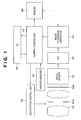
- Fig. 1 is a block diagram showing the arrangement of a digital camera according to the first embodiment of the present invention
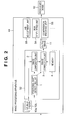
- Fig. 2 is a block diagram showing the arrangement of an image processing apparatus according to the first embodiment
- Fig. 3 is a block diagram showing an image processing unit extracted from the image processing apparatus shown in Fig. 2, and the data sequence of an image processing method according to the first embodiment;
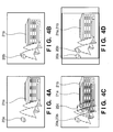
- Figs. 4A and 4B are schematic views showing two images to be given to a positional shift detection unit
- Fig. 4C is a schematic view when the two images shown in Figs. 4A and 4B are superposed without any positioning;
- Fig. 4D is a schematic view when the two images shown in Figs. 4A and 4B are superposed after positioning;
- Figs. 5A to 5C are schematic views showing two images before composition and a composited image
- Fig. 6 is a block diagram showing the internal arrangement of an image processing apparatus according to the second embodiment
- Figs. 7A and 7B are schematic views showing the relationship between an aperture stop and an image of a foreign substance
- Fig. 8 is a block diagram showing an image processing unit extracted from the image processing apparatus shown in Fig. 6, and the data sequence of an image processing method according to the second embodiment;
- Fig. 9 is a schematic view showing an image obtained by superposing two given images without any positioning.
- Fig. 1 is a block diagram showing the arrangement of a digital camera according to the first embodiment of the present invention.
- reference numeral 41 denotes a photographing optical system which forms an object image
- 41a an aperture stop which is accommodated in the photographing optical system 41 and adjusts the amount of light that enters an image sensor 42
- 42 the image sensor which photo-electrically converts the object image.
- an optical member 42a such as a lowpass filter and cover filter is arranged in its proximity. A foreign substance adheres to the surface of the optical member 42a. The adhered foreign substance is captured in the object image on the image sensor 42 as a shadow.
- Reference numeral 43 denotes an A/D converter which converts an analog image signal output from the image sensor 42 into a digital signal; and 44, an image processing apparatus which processes the digital image signal output from the A/D converter 43.
- Reference numeral 45 denotes a lens system control unit which controls the lens position of the photographing optical system 41 and the degree of opening of the aperture stop 41a; and 46, various sensors such as an AF (Auto Focus) sensor and AE (Auto Exposure) sensor.
- Reference numeral 47 denotes a camera control unit which controls the operation of the overall digital camera; 48, an I/O which interfaces with a release switch, display, and the like; and 49, a memory which stores captured images and various types of information.
- the digital camera acquires the user's operation via the I/O 48 and executes power ON/OFF, an image capturing operation, and the like in accordance with the user's instruction.
- the camera control unit 47 decides an appropriate image capturing condition on the basis of the information obtained from the various sensors 46 or image sensor 42, and sets an appropriate lens position via the lens system control unit 45.
- the output signal from the image sensor 42 is digitized via the A/D converter 43 after exposure, undergoes an appropriate image process by the image processing apparatus 44, and is saved in the memory 49.
- a display (not shown) displays the image via the I/O 48 as needed.
- the image processing apparatus 44 generally executes processes such as white balance adjustment, RGB development, and compression encoding.
- the image processing apparatus 44 according to the first embodiment comprises a composition unit which composites a plurality of images to generate one output image, in addition to the above processes.
- Fig. 2 is a block diagram showing the arrangement of the image processing apparatus 44.
- reference numeral 44 denotes the image processing apparatus; 52, an image processing unit which composites and corrects a plurality of images 10a, 10b,...; 53, a white balance adjustment unit; 54, an RGB developing unit; and 55, a compression encoding unit.
- the plurality of images 10a, 10b,... are composited to generate one output image 11, although a detailed description thereof will be omitted.
- the output image 11 undergoes an appropriate image process to obtain a high-quality compressed image, in which deterioration due to the presence of the foreign substance is corrected.
- Fig. 3 is a block diagram mainly showing the image processing unit 52 extracted from the image processing apparatus 44 shown in Fig. 2, and the data sequence of an image processing method according to the first embodiment. An image processing operation according to the first embodiment will be described with reference to Fig. 3.
- the plurality of images 10a, 10b,... shown in Figs. 2 and 3 are images obtained by continuously shooting the same object.
- one image is generated by continuously shooting the same object and generating and compositing a plurality of images.
- the reason why the same object is continuously shot to composite the plurality of captured images is as follows.
- a plurality of underexposure images are captured by increasing the shutter speed from a level at which appropriate exposure can be attained but camera shake is likely to occur to a level at which camera shake is less likely to occur.
- These plurality of images are composited to generate one image with appropriate exposure. That is, this technique captures and composites a plurality of images with underexposure which makes camera shake negligible to obtain an image with appropriate exposure which makes the influence of camera shake inconspicuous.
- the plurality of images 10a, 10b,... shown in Figs. 2 and 3 are images obtained by continuous shooting for the above purpose. Note that the plurality of images 10a, 10b,... are not limited to images captured for camera shake correction, and may be images captured to be composited for another purpose.
- a positional shift detection unit 1 and image composition unit 2 receive the plurality of images 10a, 10b,....
- the positional shift detection unit 1 detects the positional shifts between the plurality of images using, e.g., the method disclosed in Japanese Patent Laid-Open No. 2000-341582 .
- the image composition unit 2 composites the plurality of images into one image by executing positioning and exposure compensation for the plurality of images on the basis of the positional shift information calculated by the positional shift detection unit 1.
- An image correction unit 3 generates an output image 11 by correcting the composite image on the basis of the composite image obtained by the image composition unit 2, the positional shift information between the plurality of images obtained by the image composition unit 2, and foreign substance area information stored in a memory 4.
- the foreign substance area information on the memory 4 is information about an area on the neighboring portion of the image sensor, within which a foreign substance detected using, e.g., the method disclosed in Japanese Patent Laid-Open No. 2004-172820 or 2004-222231 exists.
- This foreign substance area information is information associated with the position and size of a foreign substance existing on the optical member 42a when it is seen in a captured image.
- Figs. 4A to 4D exemplify a case in which two images are to be composited, for descriptive convenience.
- Figs. 4A and 4B show a plurality of images (two images in this case) to be given to the positional shift detection unit 1.
- Fig. 4C is a schematic view when the two images shown in Figs. 4A and 4B are superposed without any positioning.
- the positional shift detection unit 1 calculates the positional shifts between a plurality of images (two images in this case) using, e.g., the method disclosed in Japanese Patent Laid-Open No. 2000-341582 .
- Fig. 4C shows the positional shift vector between the two images calculated at this time.
- the image composition unit 2 composites the two images by executing positioning on the basis of the positional shift vector between the two images calculated by the positional shift detection unit 1.
- Fig. 4D exemplifies the composited image.
- reference numerals 20a and 20b denote areas in the two images, where the image quality is degraded due to the adhesion of the foreign substance to the optical member 42a.
- Reference numerals 21a and 21b denote identical objects in these two images.
- the positional shift vector calculated by the positional shift detection unit 1 takes a value other than zero. That is, a vector 22c in Fig. 4C takes a value other than a zero vector. Even when the objects 21a and 21b are identical objects, their positions on the window do not coincide with each other.
- the image of the foreign substance adhering to the optical member 42a always exists at the fixed place on the window. That is, the areas 20a and 20b where the image quality is degraded due to the adhesion of the foreign substance coincide with each other in Fig. 4C in which the two images are superposed without any positioning.
- the positions of the objects 21a and 21b coincide with each other while those of the areas 20a and 20b where the image quality is degraded due to the adhesion of the foreign substance do not coincide with each other. That is, the composited image shown in Fig. 4D has the two areas 20a and 20b where the image quality is degraded.
- the image correction unit 3 receives positional shift information (positional shift vector) calculated by the positional shift detection unit 1, a composite image composited by the image composition unit 2, and foreign substance information (e.g., the position and size of a foreign substance) stored in the memory 4 in advance.
- the foreign substance information is calculated in advance using, e.g., the method disclosed in Japanese Patent Laid-Open No. 2004-172820 or 2004-222231 , and is accumulated on the memory 4.
- Figs. 5A to 5C are schematic views showing two images before composition and a composited image, in which Figs. 5A and 5B show two images before composition, and Fig. 5C shows a composited image.
- the information on the memory 4 is given as, e.g., the position and size of the foreign substance.
- the foreign substance areas 20a and 20b in the two images before compositions are specified.
- the positional shift detection unit 1 has already detected the positional shift information of the two images. This makes it possible to easily specify the position of the foreign substance area 20a as a foreign substance area 23b when the image shown in Fig. 5A is positioned and superposed on the image shown in Fig. 5B. Similarly, it is possible to specify the position of the foreign substance area 20b as a foreign substance area 23a when the image shown in Fig. 5B is positioned and superposed on the image shown in Fig. 5A.
- Each of the foreign substance areas 23a and 23b is assumed to be a partial image corresponding to an area where the image quality is degraded in the image which does not contain the area 23a or 23b. These partial images are corrected using the images 23a and 23b free from any image deterioration. Image correction is executed using an appropriate method of, e.g., interchanging the area 20a with the area 23b, interchanging the area 20b with the area 23a, or changing the weight in weighted mean averaging of the areas 20a and 23b and the areas 20b and 23a.
- the finally obtained image is the one which is generated using information about areas free from any image deterioration due to the presence of a so-called foreign substance to result in a high-quality image.
- Using more than two images makes it possible to more accurately take a measure against image deterioration even over a wider range.
- the first embodiment it is possible to suppress the capture of a foreign substance in the captured image to result in a high-quality image.
- the block arrangement of a digital camera in the second embodiment is the same as that in the first embodiment shown in Fig. 1 except for the internal arrangement of the image processing apparatus 44.
- Fig. 6 is a block diagram showing the internal arrangement of an image processing apparatus 44 according to the second embodiment.
- reference numeral 44 denotes the image processing apparatus; 52a, a multiple image processing unit; 53, a white balance adjustment unit; 54, an RGB developing unit; and 55, a compression encoding unit.
- the multiple image processing unit 52a differs from the image processing unit 52 according to the first embodiment shown in Fig. 2 in that a foreign substance area detection unit 5 is provided.
- the foreign substance area detection unit 5 acquires a plurality of images 10a, 10b,... with appropriate exposure in an aperture state designated by the user, and a plurality of images 13a, 13b,... obtained by narrowing down an aperture stop 41a to an extent larger than a predetermined value.
- Figs. 7A and 7B are schematic views showing the relationship between an aperture stop and an image of a foreign substance.
- Fig. 7A is a schematic view when the aperture stop is opened (i.e., the F-number is small).
- Fig. 7B is a schematic view when the aperture stop is narrowed down (i.e., the F-number is large).
- reference numerals 61a and 61b denote pupils; 62a and 62b, ranges on an image sensor, where the influence of a foreign substance reaches; 63, a foreign substance; and 64a and 64b, graphs schematically showing the magnitude of the influence of the foreign substance on the image sensor.
- narrowing down the aperture stop 41a narrows the range where the influence of the foreign substance reaches, and increases the peak at the same time to lead to a greater influence on the image signal.
- narrowing down the aperture stop 41a makes it possible to make the image of the foreign substance clear to facilitate the detection of it. This makes it possible to improve the reliability of foreign substance detection.
- the multiple image processing unit 52a detects a foreign substance using the narrowed image. On the basis of the foreign substance area information detected by this operation, the multiple image processing unit 52a corrects a plurality of images with appropriate exposure in an aperture state designated by the user to obtain an output image 11. This makes it possible to obtain a high-quality image corrected on the basis of more accurate foreign substance area information.
- Fig. 8 is a block diagram mainly showing the image processing unit 52a extracted from the image processing apparatus 44 shown in Fig. 6, and the data sequence of an image processing method according to the second embodiment. An image processing operation according to the second embodiment will be explained with reference to Fig. 8.
- a positional shift detection unit 1 and image composition unit 2 receive the plurality of images 10a, 10b,....
- the positional shift detection unit 1 detects the positional shifts between the plurality of images using, e.g., the method disclosed in Japanese Patent Laid-Open No. 2000-341582 .
- the image composition unit 2 composites the plurality of images into one image by executing positioning and exposure compensation for the plurality of images on the basis of the positional shift information calculated by the positional shift detection unit 1.
- the foreign substance area detection unit 5 On the basis of the plurality of images and the positional shift information calculated by the positional shift detection unit 1, the foreign substance area detection unit 5 detects foreign substance area information such as the position and size of a foreign substance using, e.g., the method disclosed in Japanese Patent Laid-Open No. 2004-172820 .
- An image correction unit 3 generates an output image 11 by correcting the composite image on the basis of the composite image obtained by the image composition unit 2, the positional shift information between the plurality of images obtained by the image composition unit 2, and the foreign substance area information obtained by the foreign substance area detection unit 5.
- Fig. 9 shows an image obtained by superposing a plurality of given images (two given images in this case) without any positioning.
- reference numerals 20a and 20b denote areas where the image quality is degraded due to the presence of a foreign substance.
- reference numeral 22c denotes a positional shift vector calculated by the positional shift detection unit 1.
- the positional shift detection unit 1 When the positional shift detection unit 1 appropriately calculates the positional shift information, it is possible to detect corresponding feature points of a finite number of feature points extracted with reference to contrast or the like, other than feature points generated by dirt. In contrast, since a feature point generated by dirt such as a feature point 24 shown in Fig. 9 does not shift between the plurality of images, it has no point corresponding to the head of a shift vector given by the positional shift information. This principle allows the detection of an image of a foreign substance.
- the position of a foreign substance is specified to give the specified position as foreign substance area information to the image correction unit 3.
- the image correction unit 3 corrects the image using the method shown in the first embodiment to generate an output image.
- the finally obtained image is the one which is generated using information about areas free from any image deterioration due to the presence of a so-called foreign substance to result in a high-quality image.
- Using more than two images makes it possible to more accurately take a measure against image deterioration even over a wider range.
- the second embodiment has exemplified the case in which a plurality of images which are continuously shot with appropriate exposure are composited. However, when a plurality of images are captured with appropriate exposure without camera shake, it may be unnecessary to composite these images. In this case, a foreign substance area in one image alone may be corrected by an image of a corresponding area in the other image. This also makes it possible to eliminate the influence of the foreign substance from the image.
- the first and second embodiments have exemplified the case in which a plurality of images are composited in the camera.
- the camera may be used only to capture a plurality of images to cause an image processing apparatus outside the camera to execute an image composition process and foreign substance removal process.
- an image processing apparatus such as a PC (personal computer) is configured to incorporate the image processing unit 52 or 52a. Via a detachable recording medium or by connecting the camera and the PC, the PC can receive a plurality of images 10a, 10b,..., a plurality of images 13a, 13b,..., and foreign substance information to be input. With this arrangement, the image processing apparatus outside the camera can attain an image composition process and foreign substance removal process.
- the first and second embodiments it is possible to provide a digital camera and image processing apparatus capable of suppressing the capture of a foreign substance in the captured image to result in a high-quality image.
- a foreign substance can be detected in the digital camera simultaneously with image capture, or by the image processing apparatus such as a PC after image capture. This obviates the need for prompting the user to execute an operation in a cleaning mode to result in an improvement in user-friendliness. It is also possible to appropriately execute a correction operation even for a foreign substance adhered immediately before image capture.
- a storage medium (or recording medium) which records software program codes for implementing the functions of the above-described embodiments is supplied to the system or apparatus.
- the computer or CPU or MPU
- the program codes read out from the storage medium implement the functions of the above-described embodiments by themselves, and the storage medium which stores the program codes constitutes the present invention.
- the present invention incorporates the following case. That is, the functions of the above-described embodiments are implemented when the operating system (OS) running on the computer performs part or all of actual processing on the basis of the instructions of the program codes.
- the present invention also incorporates the following case. That is, the program codes read out from the storage medium are written in the memory of a function expansion card inserted into the computer or a function expansion unit connected to the computer. After that, the functions of the above-described embodiments are implemented when the CPU of the function expansion card or function expansion unit performs part or all of actual processing on the basis of the instructions of the program codes.
- the storage medium stores program codes corresponding to the above-described procedures.
- An image capturing apparatus includes an image sensor (42) which photo-electrically converts an object image, a memory (49) which stores foreign substance area information associated with a foreign substance adhering to an optical member disposed in front of the image sensor, a positional shift detection unit (44) which detects the mutual positional shifts between a plurality of images generated by sensing almost the same object by the image sensor, an image composition unit (44) which positions and composites the plurality of images on the basis of the detection result obtained by the positional shift detection unit, and an image correction unit (44) which corrects at least parts of the plurality of images on the basis of the detection result obtained by the positional shift detection unit and the foreign substance area information stored in the memory.
Landscapes
- Engineering & Computer Science (AREA)
- Multimedia (AREA)
- Signal Processing (AREA)
- Studio Devices (AREA)
- Image Processing (AREA)
- Camera Bodies And Camera Details Or Accessories (AREA)
- Investigating Materials By The Use Of Optical Means Adapted For Particular Applications (AREA)
Abstract
Description
- The present invention relates to a technique for suppressing the influence of a foreign substance adhering to the neighboring portion of an image sensor on the image quality in a digital camera or the like.
- In recent years, digitization of cameras are making rapid progress and, especially, a so-called digital single-lens reflex camera is becoming popular, which has the same optical layout as that of the conventional single-lens reflex camera and in which an image sensor that executes photo-electric conversion substitutes for a film. The digital single-lens reflex camera requires no film rewinding/replacement operations. Once a foreign substance enters the neighboring portion of the image sensor in the process of lens replacement or the like, the digital single-lens reflex camera continues to shoot images in which the foreign substance is captured. This degrades the quality of a series of captured images.
-
Japanese Patent Laid-Open No. 2004-172820 Japanese Patent Laid-Open No. 2004-172820 -
Japanese Patent Laid-Open No. 2004-222231 Japanese Patent Laid-Open No. 2004-222231 -
Japanese Patent Laid-Open No. 2000-341582 Japanese Patent Laid-Open No. 2000-341582 - Unfortunately, the above-described conventional techniques pose the following problems.
- The invention in
Japanese Patent Laid-Open No. 2004-172820 - The invention in
Japanese Patent Laid-Open No. 2004-222231 - The invention in
Japanese Patent Laid-Open No. 2000-341582 - The present invention has been made in consideration of the above problems, and obtains an image which is hardly influenced by a foreign substance even when it adheres to the neighboring portion of an image sensor in an image capturing apparatus.
- According to a first aspect of the present invention, there is provided an image capturing apparatus as specified in
claim 1. - According to a second aspect of the present invention, there is provided an image capturing apparatus as specified in
claim 4. - According to a third aspect of the present invention, there is provided a method of controlling an image capturing apparatus as specified in claim 10.
- According to a fourth aspect of the present invention, there is provided a method of controlling an image capturing apparatus as specified in
claim 12. - According to a fifth aspect of the present invention, there is provided an image processing apparatus as specified in claim 15.
- According to a sixth aspect of the present invention, there is provided an image processing apparatus as specified in claim 18.
- According to a seventh aspect of the present invention, there is provided an image processing method as specified in
claim 24. - According to an eighth aspect of the present invention, there is provided an image processing method as specified in claim 26.
- Further features of the present invention will become apparent from the following description of exemplary embodiments with reference to the attached drawings.
- Fig. 1 is a block diagram showing the arrangement of a digital camera according to the first embodiment of the present invention;
- Fig. 2 is a block diagram showing the arrangement of an image processing apparatus according to the first embodiment;
- Fig. 3 is a block diagram showing an image processing unit extracted from the image processing apparatus shown in Fig. 2, and the data sequence of an image processing method according to the first embodiment;
- Figs. 4A and 4B are schematic views showing two images to be given to a positional shift detection unit;
- Fig. 4C is a schematic view when the two images shown in Figs. 4A and 4B are superposed without any positioning;
- Fig. 4D is a schematic view when the two images shown in Figs. 4A and 4B are superposed after positioning;
- Figs. 5A to 5C are schematic views showing two images before composition and a composited image;
- Fig. 6 is a block diagram showing the internal arrangement of an image processing apparatus according to the second embodiment;
- Figs. 7A and 7B are schematic views showing the relationship between an aperture stop and an image of a foreign substance;
- Fig. 8 is a block diagram showing an image processing unit extracted from the image processing apparatus shown in Fig. 6, and the data sequence of an image processing method according to the second embodiment; and
- Fig. 9 is a schematic view showing an image obtained by superposing two given images without any positioning.
- Preferred embodiments of the present invention will be described in detail below with reference to the accompanying drawings.
- Fig. 1 is a block diagram showing the arrangement of a digital camera according to the first embodiment of the present invention.
- Referring to Fig. 1,
reference numeral 41 denotes a photographing optical system which forms an object image; 41a, an aperture stop which is accommodated in the photographingoptical system 41 and adjusts the amount of light that enters animage sensor 42; and 42, the image sensor which photo-electrically converts the object image. On the front surface of theimage sensor 42, anoptical member 42a such as a lowpass filter and cover filter is arranged in its proximity. A foreign substance adheres to the surface of theoptical member 42a. The adhered foreign substance is captured in the object image on theimage sensor 42 as a shadow.Reference numeral 43 denotes an A/D converter which converts an analog image signal output from theimage sensor 42 into a digital signal; and 44, an image processing apparatus which processes the digital image signal output from the A/D converter 43.Reference numeral 45 denotes a lens system control unit which controls the lens position of the photographingoptical system 41 and the degree of opening of theaperture stop 41a; and 46, various sensors such as an AF (Auto Focus) sensor and AE (Auto Exposure) sensor.Reference numeral 47 denotes a camera control unit which controls the operation of the overall digital camera; 48, an I/O which interfaces with a release switch, display, and the like; and 49, a memory which stores captured images and various types of information. - The digital camera acquires the user's operation via the I/
O 48 and executes power ON/OFF, an image capturing operation, and the like in accordance with the user's instruction. Upon receiving an image capturing operation instruction, thecamera control unit 47 decides an appropriate image capturing condition on the basis of the information obtained from thevarious sensors 46 orimage sensor 42, and sets an appropriate lens position via the lenssystem control unit 45. The output signal from theimage sensor 42 is digitized via the A/D converter 43 after exposure, undergoes an appropriate image process by theimage processing apparatus 44, and is saved in thememory 49. A display (not shown) displays the image via the I/O 48 as needed. - The
image processing apparatus 44 generally executes processes such as white balance adjustment, RGB development, and compression encoding. Theimage processing apparatus 44 according to the first embodiment comprises a composition unit which composites a plurality of images to generate one output image, in addition to the above processes. - Fig. 2 is a block diagram showing the arrangement of the
image processing apparatus 44. - Referring to Fig. 2,
reference numeral 44 denotes the image processing apparatus; 52, an image processing unit which composites and corrects a plurality ofimages - In the first embodiment, when, e.g., the user designates a mode for correcting image deterioration due to the presence of a foreign substance from a plurality of images, the plurality of
images output image 11, although a detailed description thereof will be omitted. After that, theoutput image 11 undergoes an appropriate image process to obtain a high-quality compressed image, in which deterioration due to the presence of the foreign substance is corrected. - Fig. 3 is a block diagram mainly showing the
image processing unit 52 extracted from theimage processing apparatus 44 shown in Fig. 2, and the data sequence of an image processing method according to the first embodiment. An image processing operation according to the first embodiment will be described with reference to Fig. 3. - The plurality of
images - The plurality of
images - As is well known, camera shake occurs and leads to image deterioration when a shutter speed enough for image capture cannot be attained because the object exhibits low luminance. In this case, a plurality of underexposure images are captured by increasing the shutter speed from a level at which appropriate exposure can be attained but camera shake is likely to occur to a level at which camera shake is less likely to occur. These plurality of images are composited to generate one image with appropriate exposure. That is, this technique captures and composites a plurality of images with underexposure which makes camera shake negligible to obtain an image with appropriate exposure which makes the influence of camera shake inconspicuous.
- In the first embodiment, the plurality of
images images - An image processing operation according to the first embodiment will be explained with reference to Fig. 3.
- As shown in Fig. 3, a positional
shift detection unit 1 andimage composition unit 2 receive the plurality ofimages shift detection unit 1 detects the positional shifts between the plurality of images using, e.g., the method disclosed inJapanese Patent Laid-Open No. 2000-341582 image composition unit 2 composites the plurality of images into one image by executing positioning and exposure compensation for the plurality of images on the basis of the positional shift information calculated by the positionalshift detection unit 1. Animage correction unit 3 generates anoutput image 11 by correcting the composite image on the basis of the composite image obtained by theimage composition unit 2, the positional shift information between the plurality of images obtained by theimage composition unit 2, and foreign substance area information stored in amemory 4. The foreign substance area information on thememory 4 is information about an area on the neighboring portion of the image sensor, within which a foreign substance detected using, e.g., the method disclosed inJapanese Patent Laid-Open No. 2004-172820 2004-222231 optical member 42a when it is seen in a captured image. - The operations of the positional
shift detection unit 1 andimage composition unit 2 will be explained with reference to Figs. 4A to 4D. - Figs. 4A to 4D exemplify a case in which two images are to be composited, for descriptive convenience.
- Figs. 4A and 4B show a plurality of images (two images in this case) to be given to the positional
shift detection unit 1. Fig. 4C is a schematic view when the two images shown in Figs. 4A and 4B are superposed without any positioning. - The positional
shift detection unit 1 calculates the positional shifts between a plurality of images (two images in this case) using, e.g., the method disclosed inJapanese Patent Laid-Open No. 2000-341582 image composition unit 2 composites the two images by executing positioning on the basis of the positional shift vector between the two images calculated by the positionalshift detection unit 1. Fig. 4D exemplifies the composited image. - Assume here that a foreign substance adheres to the
optical member 42a. Referring to Figs. 4A to 4D,reference numerals optical member 42a.Reference numerals - When the two images are captured not to have the same picture composition, the positional shift vector calculated by the positional
shift detection unit 1 takes a value other than zero. That is, avector 22c in Fig. 4C takes a value other than a zero vector. Even when theobjects - The image of the foreign substance adhering to the
optical member 42a always exists at the fixed place on the window. That is, theareas objects areas areas - The operation of the
image correction unit 3 serving as the main part of the first embodiment will be explained with reference to Figs. 3 and 5A to 5C. - The
image correction unit 3 receives positional shift information (positional shift vector) calculated by the positionalshift detection unit 1, a composite image composited by theimage composition unit 2, and foreign substance information (e.g., the position and size of a foreign substance) stored in thememory 4 in advance. The foreign substance information is calculated in advance using, e.g., the method disclosed inJapanese Patent Laid-Open No. 2004-172820 2004-222231 memory 4. - Figs. 5A to 5C are schematic views showing two images before composition and a composited image, in which Figs. 5A and 5B show two images before composition, and Fig. 5C shows a composited image.
- Referring to Figs. 5A to 5C, the information on the
memory 4 is given as, e.g., the position and size of the foreign substance. As shown in Figs. 5A and 5B, theforeign substance areas shift detection unit 1 has already detected the positional shift information of the two images. This makes it possible to easily specify the position of theforeign substance area 20a as aforeign substance area 23b when the image shown in Fig. 5A is positioned and superposed on the image shown in Fig. 5B. Similarly, it is possible to specify the position of theforeign substance area 20b as aforeign substance area 23a when the image shown in Fig. 5B is positioned and superposed on the image shown in Fig. 5A. - Each of the
foreign substance areas area images area 20a with thearea 23b, interchanging thearea 20b with thearea 23a, or changing the weight in weighted mean averaging of theareas areas - The finally obtained image is the one which is generated using information about areas free from any image deterioration due to the presence of a so-called foreign substance to result in a high-quality image. Using more than two images makes it possible to more accurately take a measure against image deterioration even over a wider range.
- As described above, according to the first embodiment, it is possible to suppress the capture of a foreign substance in the captured image to result in a high-quality image.
- The block arrangement of a digital camera in the second embodiment is the same as that in the first embodiment shown in Fig. 1 except for the internal arrangement of the
image processing apparatus 44. - Fig. 6 is a block diagram showing the internal arrangement of an
image processing apparatus 44 according to the second embodiment. Referring to Fig. 6,reference numeral 44 denotes the image processing apparatus; 52a, a multiple image processing unit; 53, a white balance adjustment unit; 54, an RGB developing unit; and 55, a compression encoding unit. The multipleimage processing unit 52a differs from theimage processing unit 52 according to the first embodiment shown in Fig. 2 in that a foreign substancearea detection unit 5 is provided. - The operation of the foreign substance
area detection unit 5 according to the second embodiment will be explained with reference to Fig. 6. - When, e.g., the user designates a mode for correcting image deterioration due to the presence of a foreign substance from a plurality of images, the foreign substance
area detection unit 5 acquires a plurality ofimages images aperture stop 41a to an extent larger than a predetermined value. - Figs. 7A and 7B are schematic views showing the relationship between an aperture stop and an image of a foreign substance. Fig. 7A is a schematic view when the aperture stop is opened (i.e., the F-number is small). Fig. 7B is a schematic view when the aperture stop is narrowed down (i.e., the F-number is large).
- Referring to Figs. 7A and 7B,
reference numerals aperture stop 41a narrows the range where the influence of the foreign substance reaches, and increases the peak at the same time to lead to a greater influence on the image signal. As a result, narrowing down theaperture stop 41a makes it possible to make the image of the foreign substance clear to facilitate the detection of it. This makes it possible to improve the reliability of foreign substance detection. - The multiple
image processing unit 52a detects a foreign substance using the narrowed image. On the basis of the foreign substance area information detected by this operation, the multipleimage processing unit 52a corrects a plurality of images with appropriate exposure in an aperture state designated by the user to obtain anoutput image 11. This makes it possible to obtain a high-quality image corrected on the basis of more accurate foreign substance area information. - Fig. 8 is a block diagram mainly showing the
image processing unit 52a extracted from theimage processing apparatus 44 shown in Fig. 6, and the data sequence of an image processing method according to the second embodiment. An image processing operation according to the second embodiment will be explained with reference to Fig. 8. - As shown in Fig. 8, a positional
shift detection unit 1 andimage composition unit 2 receive the plurality ofimages shift detection unit 1 detects the positional shifts between the plurality of images using, e.g., the method disclosed inJapanese Patent Laid-Open No. 2000-341582 image composition unit 2 composites the plurality of images into one image by executing positioning and exposure compensation for the plurality of images on the basis of the positional shift information calculated by the positionalshift detection unit 1. On the basis of the plurality of images and the positional shift information calculated by the positionalshift detection unit 1, the foreign substancearea detection unit 5 detects foreign substance area information such as the position and size of a foreign substance using, e.g., the method disclosed inJapanese Patent Laid-Open No. 2004-172820 image correction unit 3 generates anoutput image 11 by correcting the composite image on the basis of the composite image obtained by theimage composition unit 2, the positional shift information between the plurality of images obtained by theimage composition unit 2, and the foreign substance area information obtained by the foreign substancearea detection unit 5. - The operations of the positional
shift detection unit 1,image composition unit 2, andimage correction unit 3 are the same as those in the first embodiment, and a repetitive description thereof will be omitted. - The operation of the foreign substance
area detection unit 5 will be explained with reference to Fig. 9. - Fig. 9 shows an image obtained by superposing a plurality of given images (two given images in this case) without any positioning. Referring to Fig. 9,
reference numerals reference numeral 22c denotes a positional shift vector calculated by the positionalshift detection unit 1. - When the positional
shift detection unit 1 appropriately calculates the positional shift information, it is possible to detect corresponding feature points of a finite number of feature points extracted with reference to contrast or the like, other than feature points generated by dirt. In contrast, since a feature point generated by dirt such as afeature point 24 shown in Fig. 9 does not shift between the plurality of images, it has no point corresponding to the head of a shift vector given by the positional shift information. This principle allows the detection of an image of a foreign substance. - With, e.g., the above-described method, the position of a foreign substance is specified to give the specified position as foreign substance area information to the
image correction unit 3. - The
image correction unit 3 corrects the image using the method shown in the first embodiment to generate an output image. - The finally obtained image is the one which is generated using information about areas free from any image deterioration due to the presence of a so-called foreign substance to result in a high-quality image. Using more than two images makes it possible to more accurately take a measure against image deterioration even over a wider range.
- The second embodiment has exemplified the case in which a plurality of images which are continuously shot with appropriate exposure are composited. However, when a plurality of images are captured with appropriate exposure without camera shake, it may be unnecessary to composite these images. In this case, a foreign substance area in one image alone may be corrected by an image of a corresponding area in the other image. This also makes it possible to eliminate the influence of the foreign substance from the image.
- The first and second embodiments have exemplified the case in which a plurality of images are composited in the camera. However, the camera may be used only to capture a plurality of images to cause an image processing apparatus outside the camera to execute an image composition process and foreign substance removal process.
- More specifically, an image processing apparatus such as a PC (personal computer) is configured to incorporate the
image processing unit images images - As has been described above, according to the first and second embodiments, it is possible to provide a digital camera and image processing apparatus capable of suppressing the capture of a foreign substance in the captured image to result in a high-quality image. A foreign substance can be detected in the digital camera simultaneously with image capture, or by the image processing apparatus such as a PC after image capture. This obviates the need for prompting the user to execute an operation in a cleaning mode to result in an improvement in user-friendliness. It is also possible to appropriately execute a correction operation even for a foreign substance adhered immediately before image capture.
- The object of each embodiment is achieved even by the following method. That is, a storage medium (or recording medium) which records software program codes for implementing the functions of the above-described embodiments is supplied to the system or apparatus. The computer (or CPU or MPU) of the system or apparatus reads out and executes the program codes stored in the storage medium. In this case, the program codes read out from the storage medium implement the functions of the above-described embodiments by themselves, and the storage medium which stores the program codes constitutes the present invention. In addition to the case in which the functions of the above-described embodiments are implemented when the readout program codes are executed by the computer, the present invention incorporates the following case. That is, the functions of the above-described embodiments are implemented when the operating system (OS) running on the computer performs part or all of actual processing on the basis of the instructions of the program codes.
- The present invention also incorporates the following case. That is, the program codes read out from the storage medium are written in the memory of a function expansion card inserted into the computer or a function expansion unit connected to the computer. After that, the functions of the above-described embodiments are implemented when the CPU of the function expansion card or function expansion unit performs part or all of actual processing on the basis of the instructions of the program codes.
- When the present invention is applied to the storage medium, the storage medium stores program codes corresponding to the above-described procedures.
- While the present invention has been described with reference to exemplary embodiments, it is to be understood that the invention is not limited to the disclosed exemplary embodiments. The scope of the following claims is to be accorded the broadest interpretation so as to encompass all such modifications and equivalent structures and functions. An image capturing apparatus includes an image sensor (42) which photo-electrically converts an object image, a memory (49) which stores foreign substance area information associated with a foreign substance adhering to an optical member disposed in front of the image sensor, a positional shift detection unit (44) which detects the mutual positional shifts between a plurality of images generated by sensing almost the same object by the image sensor, an image composition unit (44) which positions and composites the plurality of images on the basis of the detection result obtained by the positional shift detection unit, and an image correction unit (44) which corrects at least parts of the plurality of images on the basis of the detection result obtained by the positional shift detection unit and the foreign substance area information stored in the memory.
Claims (28)
- An image capturing apparatus comprising:an image sensor (42) which photo-electrically converts an object image;storage means (49) for storing foreign substance area information which is associated with a foreign substance adhering to an optical member (42a) disposed in front of said image sensor and contains at least position information of the foreign substance;positional shift detection means (1) for detecting mutual positional shifts between a plurality of images generated by sensing substantially the same object by said image sensor;image composition means (2) for positioning and compositing the plurality of images on the basis of the detection result obtained by said positional shift detection means; andimage correction means (3) for correcting at least parts of the plurality of images on the basis of the detection result obtained by said positional shift detection means and the foreign substance area information stored in said storage means.
- The apparatus according to claim 1, wherein said image correction means corrects a partial image, in which the foreign substance is captured, in a first image as one of the plurality of images by a partial image, in which the foreign substance is not captured, in a second image different from the first image of the plurality of images, on the basis of the detection result obtained by said positional shift detection means and the foreign substance area information stored in said storage means.
- The apparatus according to claim 2, wherein the partial image in which the foreign substance is captured and the partial image in which the foreign substance is not captured are images, corresponding to the same portion of the object, in the first image and the second image.
- An image capturing apparatus comprising:an image sensor (42) which photo-electrically converts an object image;foreign substance area detection means (5) for detecting foreign substance area information which is associated with a foreign substance adhering to an optical member (42a) disposed in front of said image sensor and contains at least position information of the foreign substance;positional shift detection means (1) for detecting mutual positional shifts between a plurality of images generated by sensing substantially the same object by said image sensor;image composition means (2) for positioning and compositing the plurality of images on the basis of the detection result obtained by said positional shift detection means; andimage correction means (3) for correcting at least parts of the plurality of images on the basis of the detection result obtained by said positional shift detection means and the foreign substance area information detected by said foreign substance area detection means.
- The apparatus according to claim 4, wherein said image correction means corrects a partial image, in which the foreign substance is captured, in a first image as one of the plurality of images by a partial image, in which the foreign substance is not captured, in a second image different from the first image of the plurality of images, on the basis of the detection result obtained by said positional shift detection means and the foreign substance area information detected by said foreign substance area detection means.
- The apparatus according to claim 5, wherein the partial image in which the foreign substance is captured and the partial image in which the foreign substance is not captured are images, corresponding to the same portion of the object, in the first image and the second image.
- The apparatus according to claim 4, wherein said foreign substance area detection means detects, as a foreign substance area, an area which exhibits a positional shift different from positional shifts of the other portions within a window in the detection result obtained by said positional shift detection means.
- The apparatus according to claim 4, wherein said foreign substance area detection means receives an image different from the plurality of images.
- The apparatus according to claim 8, wherein said foreign substance area detection means receives an image captured with a smaller aperture diameter than a predetermined aperture diameter.
- A method of controlling an image capturing apparatus including an image sensor (42) which photo-electrically converts an object image, and storage means (49) for storing foreign substance area information which is associated with a foreign substance adhering to an optical member (42a) disposed in front of the image sensor and contains at least position information of the foreign substance, comprising:a positional shift detection step of detecting mutual positional shifts between a plurality of images generated by sensing substantially the same object by the image sensor;an image composition step of positioning and compositing the plurality of images on the basis of the detection result obtained in the positional shift detection step; andan image correction step of correcting at least parts of the plurality of images on the basis of the detection result obtained in the positional shift detection step and the foreign substance area information stored in the storage means.
- The method according to claim 10, wherein in the image correction step, a partial image, in which the foreign substance is captured, in a first image as one of the plurality of images is corrected by a partial image, in which the foreign substance is not captured, in a second image different from the first image of the plurality of images, on the basis of the detection result obtained in the positional shift detection step and the foreign substance area information stored in the storage means.
- A method of controlling an image capturing apparatus including an image sensor (42) which photo-electrically converts an object image, comprising:a foreign substance area detection step of detecting foreign substance area information which is associated with a foreign substance adhering to an optical member (42a) disposed in front of the image sensor and contains at least position information of the foreign substance;a positional shift detection step of detecting mutual positional shifts between a plurality of images generated by sensing substantially the same object by the image sensor;an image composition step of positioning and compositing the plurality of images on the basis of the detection result obtained in the positional shift detection step; andan image correction step of correcting at least parts of the plurality of images on the basis of the detection result obtained in the positional shift detection step and the foreign substance area information detected in the foreign substance area detection step.
- The method according to claim 12, wherein in the image correction step, a partial image, in which the foreign substance is captured, in a first image as one of the plurality of images is corrected by a partial image, in which the foreign substance is not captured, in a second image different from the first image of the plurality of images, on the basis of the detection result obtained in the positional shift detection step and the foreign substance area information detected in the foreign substance area detection step.
- A program for causing a computer to execute a control method defined in any one of claims 10 to 13.
- An image processing apparatus comprising:acquisition means (52) for acquiring a plurality of images generated by capturing substantially the same object by an image capturing apparatus, and foreign substance area information which is associated with a foreign substance adhering to an optical member (42a) disposed in front of an image sensor (42) of the image capturing apparatus and contains at least position information of the foreign substance;positional shift detection means (1) for detecting mutual positional shifts between the plurality of images;image composition means (2) for positioning and compositing the plurality of images on the basis of the detection result obtained by said positional shift detection means; andimage correction means (3) for correcting at least part, of the plurality of images on the basis of the detection result obtained by said positional shift detection means and the foreign substance area information.
- The apparatus according to claim 15, wherein said image correction means corrects a partial image, in which the foreign substance is captured, in a first image as one of the plurality of images by a partial image, in which the foreign substance is not captured, in a second image different from the first image of the plurality of images, on the basis of the detection result obtained by said positional shift detection means and the foreign substance area information.
- The apparatus according to claim 16, wherein the partial image in which the foreign substance is captured and the partial image in which the foreign substance is not captured are images, corresponding to the same portion of the object, in the first image and the second image.
- An image processing apparatus comprising:acquisition means (52a) for acquiring a plurality of images generated by capturing substantially the same object by an image capturing apparatus;positional shift detection means (1) for detecting mutual positional shifts between the plurality of images;foreign substance area detection means (5) for detecting foreign substance area information which is associated with a foreign substance adhering to an optical member disposed in front of an image sensor arranged in the image capturing apparatus and contains at least position information of the foreign substance;image composition means (2) for positioning and compositing the plurality of images on the basis of the detection result obtained by said positional shift detection means; andimage correction means (3) for correcting at least parts of the plurality of images on the basis of the detection result obtained by said positional shift detection means and the foreign substance area information detected by said foreign substance area detection means.
- The apparatus according to claim 18, wherein said image correction means corrects a partial image, in which the foreign substance is captured, in a first image as one of the plurality of images by a partial image, in which the foreign substance is not captured, in a second image different from the first image of the plurality of images, on the basis of the detection result obtained by said positional shift detection means and the foreign substance area information detected by said foreign substance area detection means.
- The apparatus according to claim 19, wherein the partial image in which the foreign substance is captured and the partial image in which the foreign substance is not captured are images, corresponding to the same portion of the object, in the first image and the second image.
- The apparatus according to claim 18, wherein said foreign substance area detection means detects, as a foreign substance area, an area which exhibits a positional shift different from positional shifts of the other portions within a window in the detection result obtained by said positional shift detection means.
- The apparatus according to claim 18, wherein said foreign substance area detection means receives an image different from the plurality of images.
- The apparatus according to claim 22, wherein said foreign substance area detection means receives an image captured with a smaller aperture diameter than a predetermined aperture diameter.
- An image processing method comprising:an acquisition step of acquiring a plurality of images generated by capturing substantially the same object by an image capturing apparatus, and foreign substance area information which is associated with a foreign substance adhering to an optical member (42a) disposed in front of an image sensor (42) of the image capturing apparatus and contains at least position information of the foreign substance;a positional shift detection step of detecting mutual positional shifts between the plurality of images;an image composition step of positioning and compositing the plurality of images on the basis of the detection result obtained in the positional shift detection step; andan image correction step of correcting at least parts of the plurality of images on the basis of the detection result obtained in the positional shift detection step and the foreign substance area information.
- The method according to claim 24, wherein in the image correction step, a partial image, in which the foreign substance is captured, in a first image as one of the plurality of images is corrected by a partial image, in which the foreign substance is not captured, in a second image different from the first image of the plurality of images, on the basis of the detection result obtained in the positional shift detection step and the foreign substance area information.
- An image processing method comprising:an acquisition step of acquiring a plurality of images generated by capturing substantially the same object by an image capturing apparatus;a positional shift detection step of detecting mutual positional shifts between the plurality of images;a foreign substance area detection step of detecting foreign substance area information which is associated with a foreign substance adhering to an optical member disposed in front of an image sensor arranged in the image capturing apparatus and contains at least position information of the foreign substance;an image composition step of positioning and compositing the plurality of images on the basis of the detection result obtained in the positional shift detection step; andan image correction step of correcting at least parts of the plurality of images on the basis of the detection result obtained in the positional shift detection step and the foreign substance area information detected in the foreign substance area detection step.
- The method according to claim 26, wherein in the image correction step, a partial image, in which the foreign substance is captured, in a first image as one of the plurality of images is corrected by a partial image, in which the foreign substance is not captured, in a second image different from the first image of the plurality of images, on the basis of the detection result obtained in the positional shift detection step and the foreign substance area information detected in the foreign substance area detection step.
- A program for causing a computer to execute an image processing method defined in any one of claims 24 to 27.
Applications Claiming Priority (1)
| Application Number | Priority Date | Filing Date | Title |
|---|---|---|---|
| JP2006112750A JP4757085B2 (en) | 2006-04-14 | 2006-04-14 | IMAGING DEVICE AND ITS CONTROL METHOD, IMAGE PROCESSING DEVICE, IMAGE PROCESSING METHOD, AND PROGRAM |
Publications (3)
| Publication Number | Publication Date |
|---|---|
| EP1845709A2 true EP1845709A2 (en) | 2007-10-17 |
| EP1845709A3 EP1845709A3 (en) | 2011-01-19 |
| EP1845709B1 EP1845709B1 (en) | 2014-07-09 |
Family
ID=38283172
Family Applications (1)
| Application Number | Title | Priority Date | Filing Date |
|---|---|---|---|
| EP07106043.8A Not-in-force EP1845709B1 (en) | 2006-04-14 | 2007-04-12 | Image capturing apparatus, control method therefor, image processing apparatus, image processing method, and program |
Country Status (5)
| Country | Link |
|---|---|
| US (1) | US8274582B2 (en) |
| EP (1) | EP1845709B1 (en) |
| JP (1) | JP4757085B2 (en) |
| KR (1) | KR100829470B1 (en) |
| CN (1) | CN100525384C (en) |
Families Citing this family (18)
| Publication number | Priority date | Publication date | Assignee | Title |
|---|---|---|---|---|
| US8888680B2 (en) * | 2008-07-07 | 2014-11-18 | Olympus Medical Systems Corp. | Method and apparatus for foreign matter detection for blood content sensors |
| JP5231119B2 (en) * | 2008-07-31 | 2013-07-10 | オリンパス株式会社 | Display device |
| US8130278B2 (en) * | 2008-08-01 | 2012-03-06 | Omnivision Technologies, Inc. | Method for forming an improved image using images with different resolutions |
| JP5106335B2 (en) * | 2008-09-24 | 2012-12-26 | キヤノン株式会社 | Imaging apparatus, control method thereof, and program |
| JP5131257B2 (en) * | 2009-08-27 | 2013-01-30 | カシオ計算機株式会社 | Display control apparatus and display control program |
| JP5462560B2 (en) * | 2009-09-08 | 2014-04-02 | キヤノン株式会社 | Image processing device |
| JP2011078047A (en) * | 2009-10-02 | 2011-04-14 | Sanyo Electric Co Ltd | Imaging apparatus |
| US8606009B2 (en) | 2010-02-04 | 2013-12-10 | Microsoft Corporation | High dynamic range image generation and rendering |
| EP2503364A1 (en) * | 2011-03-22 | 2012-09-26 | Koninklijke Philips Electronics N.V. | Camera system comprising a camera, camera, method of operating a camera and method for deconvoluting a recorded image |
| DE102011077296B4 (en) * | 2011-06-09 | 2020-12-10 | Carl Zeiss Smt Gmbh | Method and device for determining the position of a first structure relative to a second structure or a part thereof |
| SE1250048A1 (en) * | 2012-01-24 | 2013-07-25 | Wesdyne Sweden Ab | An image enhancement device for noise reduction in digital images |
| JP6115069B2 (en) * | 2012-10-17 | 2017-04-19 | セイコーエプソン株式会社 | Electronic device, control device for electronic device, driving method for electronic device, driving method for electro-optical device |
| JP6348770B2 (en) * | 2014-05-08 | 2018-06-27 | 日産自動車株式会社 | Camera device and three-dimensional object detection device |
| JP6387455B2 (en) * | 2015-03-27 | 2018-09-05 | 富士フイルム株式会社 | Camera apparatus, image processing apparatus, and image processing method |
| CN105227851B (en) * | 2015-11-09 | 2019-09-24 | 联想(北京)有限公司 | Image processing method and image collecting device |
| CN113632450B (en) * | 2019-03-26 | 2023-07-04 | 株式会社小糸制作所 | Imaging system and image processing apparatus |
| US12165552B2 (en) * | 2020-01-22 | 2024-12-10 | Sony Semiconductor Solutions Corporation | Electronic apparatus |
| US20230209220A1 (en) * | 2020-06-17 | 2023-06-29 | Sony Group Corporation | Image processing device, image processing method, and image processing program |
Citations (5)
| Publication number | Priority date | Publication date | Assignee | Title |
|---|---|---|---|---|
| JP2000341582A (en) | 1999-05-31 | 2000-12-08 | Sony Corp | Imaging device and method thereof |
| US20040041936A1 (en) | 2002-08-30 | 2004-03-04 | Nikon Corporation | Electronic amera and control program of same |
| JP2004172820A (en) | 2002-11-19 | 2004-06-17 | Minolta Co Ltd | Imaging device |
| JP2004222231A (en) | 2002-12-27 | 2004-08-05 | Nikon Corp | Image processing apparatus and image processing program |
| US20040207738A1 (en) | 2001-03-30 | 2004-10-21 | Alain Wacker | Digital photography method and digital camera |
Family Cites Families (18)
| Publication number | Priority date | Publication date | Assignee | Title |
|---|---|---|---|---|
| JPH09212626A (en) * | 1996-02-01 | 1997-08-15 | Hitachi Ltd | Image editing method and editing apparatus |
| JPH11272855A (en) * | 1998-03-23 | 1999-10-08 | Leben:Kk | Method for removing obstacle from picked-up image |
| JP3461482B2 (en) * | 1999-02-24 | 2003-10-27 | オリンパス光学工業株式会社 | Digital camera and dust position detection method for digital camera |
| GB9921331D0 (en) * | 1999-09-09 | 1999-11-10 | Pandora Int Ltd | Film restoration system |
| CN1160210C (en) * | 1999-09-20 | 2004-08-04 | 松下电器产业株式会社 | driving reminder device |
| US6928192B2 (en) * | 2001-04-19 | 2005-08-09 | Koninklijke Philips Electronics N.V. | User interface for interactive removal of defects in an image sequence |
| US7120315B2 (en) * | 2002-03-18 | 2006-10-10 | Creo Il., Ltd | Method and apparatus for capturing images using blemished sensors |
| CN101778203B (en) * | 2002-12-27 | 2012-06-06 | 株式会社尼康 | Image processing device |
| JP2004341582A (en) | 2003-05-13 | 2004-12-02 | Nippon Telegr & Teleph Corp <Ntt> | Multipoint connection terminal device, multipoint connection terminal device connection method, multipoint connection terminal device connection program, and recording medium storing the program |
| US7209601B2 (en) * | 2003-07-22 | 2007-04-24 | Omnivision Technologies, Inc. | CMOS image sensor using high frame rate with frame addition and movement compensation |
| US7206461B2 (en) * | 2003-09-30 | 2007-04-17 | Fotonation Vision Limited | Digital image acquisition and processing system |
| JP2006038582A (en) | 2004-07-26 | 2006-02-09 | Dainippon Screen Mfg Co Ltd | Detection of flaw due to regional division of image |
| JPWO2006022229A1 (en) * | 2004-08-25 | 2008-05-08 | 松下電器産業株式会社 | Imaging optical device, captured image processing system, and captured image processing program |
| JP4480147B2 (en) * | 2004-09-13 | 2010-06-16 | キヤノン株式会社 | Imaging apparatus and control method thereof |
| US7450778B2 (en) * | 2005-03-17 | 2008-11-11 | Hewlett-Packard Development Company, L.P. | Artifact reduction in a digital video |
| US7548659B2 (en) * | 2005-05-13 | 2009-06-16 | Microsoft Corporation | Video enhancement |
| US7440608B2 (en) * | 2005-05-31 | 2008-10-21 | Hewlett-Packard Development Company, L.P. | Method and system for detecting image defects |
| JP2008072565A (en) * | 2006-09-15 | 2008-03-27 | Ricoh Co Ltd | Imaging apparatus and defective pixel correction method |
-
2006
- 2006-04-14 JP JP2006112750A patent/JP4757085B2/en not_active Expired - Fee Related
-
2007
- 2007-04-04 KR KR1020070033287A patent/KR100829470B1/en not_active Expired - Fee Related
- 2007-04-12 US US11/734,505 patent/US8274582B2/en not_active Expired - Fee Related
- 2007-04-12 EP EP07106043.8A patent/EP1845709B1/en not_active Not-in-force
- 2007-04-13 CN CNB200710096349XA patent/CN100525384C/en not_active Expired - Fee Related
Patent Citations (5)
| Publication number | Priority date | Publication date | Assignee | Title |
|---|---|---|---|---|
| JP2000341582A (en) | 1999-05-31 | 2000-12-08 | Sony Corp | Imaging device and method thereof |
| US20040207738A1 (en) | 2001-03-30 | 2004-10-21 | Alain Wacker | Digital photography method and digital camera |
| US20040041936A1 (en) | 2002-08-30 | 2004-03-04 | Nikon Corporation | Electronic amera and control program of same |
| JP2004172820A (en) | 2002-11-19 | 2004-06-17 | Minolta Co Ltd | Imaging device |
| JP2004222231A (en) | 2002-12-27 | 2004-08-05 | Nikon Corp | Image processing apparatus and image processing program |
Also Published As
| Publication number | Publication date |
|---|---|
| US8274582B2 (en) | 2012-09-25 |
| CN101056354A (en) | 2007-10-17 |
| CN100525384C (en) | 2009-08-05 |
| KR100829470B1 (en) | 2008-05-16 |
| JP4757085B2 (en) | 2011-08-24 |
| US20070242140A1 (en) | 2007-10-18 |
| EP1845709A3 (en) | 2011-01-19 |
| EP1845709B1 (en) | 2014-07-09 |
| JP2007286846A (en) | 2007-11-01 |
| KR20070102395A (en) | 2007-10-18 |
Similar Documents
| Publication | Publication Date | Title |
|---|---|---|
| US8274582B2 (en) | Image capturing apparatus, control method therefor, image processing apparatus, image processing method, and program | |
| CN104065868B (en) | Image capture apparatus and control method thereof | |
| JP4186699B2 (en) | Imaging apparatus and image processing apparatus | |
| JP5523143B2 (en) | Imaging apparatus and automatic focusing method | |
| US8294795B2 (en) | Image capturing apparatus and medium storing image processing program | |
| US8040379B2 (en) | Imaging apparatus and recording medium | |
| US7680402B2 (en) | Image shooting device with camera shake correction function | |
| US20080025650A1 (en) | Image processing apparatus, control method therefor, and program | |
| CN101622861B (en) | Image capturing apparatus, control method therefor | |
| KR101728042B1 (en) | Digital photographing apparatus and control method thereof | |
| US7817186B2 (en) | Camera and image processing method for synthesizing plural images forming one image group to generate a synthesized image | |
| US8576306B2 (en) | Image sensing apparatus, image processing apparatus, control method, and computer-readable medium | |
| US20070147814A1 (en) | Image capturing apparatus, method of controlling the same, and storage medium | |
| JP4732303B2 (en) | Imaging device | |
| JP2003101862A (en) | Imaging device and imaging method | |
| JP4953770B2 (en) | Imaging device | |
| JP5383361B2 (en) | Imaging apparatus, control method therefor, and program | |
| JP2002142158A (en) | Imaging device and correction method | |
| JP2010062825A (en) | Imaging device and method of controlling imaging | |
| JP2006203346A (en) | Electronic camera | |
| JP4750630B2 (en) | Image processing apparatus, image processing method, program, storage medium, and imaging apparatus | |
| JP5644180B2 (en) | Imaging apparatus, imaging method, and program | |
| JP4952462B2 (en) | Imaging apparatus and imaging method | |
| JP2004112487A (en) | Shooting condition judgment device | |
| JP2006243609A (en) | Autofocus device |
Legal Events
| Date | Code | Title | Description |
|---|---|---|---|
| PUAI | Public reference made under article 153(3) epc to a published international application that has entered the european phase |
Free format text: ORIGINAL CODE: 0009012 |
|
| AK | Designated contracting states |
Kind code of ref document: A2 Designated state(s): AT BE BG CH CY CZ DE DK EE ES FI FR GB GR HU IE IS IT LI LT LU LV MC MT NL PL PT RO SE SI SK TR |
|
| AX | Request for extension of the european patent |
Extension state: AL BA HR MK YU |
|
| PUAL | Search report despatched |
Free format text: ORIGINAL CODE: 0009013 |
|
| AK | Designated contracting states |
Kind code of ref document: A3 Designated state(s): AT BE BG CH CY CZ DE DK EE ES FI FR GB GR HU IE IS IT LI LT LU LV MC MT NL PL PT RO SE SI SK TR |
|
| AX | Request for extension of the european patent |
Extension state: AL BA HR MK RS |
|
| 17P | Request for examination filed |
Effective date: 20110719 |
|
| AKX | Designation fees paid |
Designated state(s): DE FR GB |
|
| 17Q | First examination report despatched |
Effective date: 20130221 |
|
| REG | Reference to a national code |
Ref country code: DE Ref legal event code: R079 Ref document number: 602007037532 Country of ref document: DE Free format text: PREVIOUS MAIN CLASS: H04N0005217000 Ipc: H04N0005357000 |
|
| GRAP | Despatch of communication of intention to grant a patent |
Free format text: ORIGINAL CODE: EPIDOSNIGR1 |
|
| RIC1 | Information provided on ipc code assigned before grant |
Ipc: H04N 5/357 20110101AFI20130904BHEP |
|
| INTG | Intention to grant announced |
Effective date: 20130916 |
|
| GRAS | Grant fee paid |
Free format text: ORIGINAL CODE: EPIDOSNIGR3 |
|
| GRAP | Despatch of communication of intention to grant a patent |
Free format text: ORIGINAL CODE: EPIDOSNIGR1 |
|
| INTG | Intention to grant announced |
Effective date: 20140409 |
|
| GRAS | Grant fee paid |
Free format text: ORIGINAL CODE: EPIDOSNIGR3 |
|
| GRAA | (expected) grant |
Free format text: ORIGINAL CODE: 0009210 |
|
| AK | Designated contracting states |
Kind code of ref document: B1 Designated state(s): DE FR GB |
|
| REG | Reference to a national code |
Ref country code: GB Ref legal event code: FG4D |
|
| REG | Reference to a national code |
Ref country code: DE Ref legal event code: R096 Ref document number: 602007037532 Country of ref document: DE Effective date: 20140821 |
|
| REG | Reference to a national code |
Ref country code: DE Ref legal event code: R097 Ref document number: 602007037532 Country of ref document: DE |
|
| PLBE | No opposition filed within time limit |
Free format text: ORIGINAL CODE: 0009261 |
|
| STAA | Information on the status of an ep patent application or granted ep patent |
Free format text: STATUS: NO OPPOSITION FILED WITHIN TIME LIMIT |
|
| 26N | No opposition filed |
Effective date: 20150410 |
|
| REG | Reference to a national code |
Ref country code: FR Ref legal event code: ST Effective date: 20151231 |
|
| PG25 | Lapsed in a contracting state [announced via postgrant information from national office to epo] |
Ref country code: FR Free format text: LAPSE BECAUSE OF NON-PAYMENT OF DUE FEES Effective date: 20150430 |
|
| PGFP | Annual fee paid to national office [announced via postgrant information from national office to epo] |
Ref country code: DE Payment date: 20160430 Year of fee payment: 10 Ref country code: GB Payment date: 20160427 Year of fee payment: 10 |
|
| REG | Reference to a national code |
Ref country code: DE Ref legal event code: R119 Ref document number: 602007037532 Country of ref document: DE |
|
| GBPC | Gb: european patent ceased through non-payment of renewal fee |
Effective date: 20170412 |
|
| PG25 | Lapsed in a contracting state [announced via postgrant information from national office to epo] |
Ref country code: DE Free format text: LAPSE BECAUSE OF NON-PAYMENT OF DUE FEES Effective date: 20171103 |
|
| PG25 | Lapsed in a contracting state [announced via postgrant information from national office to epo] |
Ref country code: GB Free format text: LAPSE BECAUSE OF NON-PAYMENT OF DUE FEES Effective date: 20170412 |