EP1845260A2 - Control valve for variable displacement compressor - Google Patents
Control valve for variable displacement compressor Download PDFInfo
- Publication number
- EP1845260A2 EP1845260A2 EP07007321A EP07007321A EP1845260A2 EP 1845260 A2 EP1845260 A2 EP 1845260A2 EP 07007321 A EP07007321 A EP 07007321A EP 07007321 A EP07007321 A EP 07007321A EP 1845260 A2 EP1845260 A2 EP 1845260A2
- Authority
- EP
- European Patent Office
- Prior art keywords
- valve
- plunger
- valve rod
- compressor
- pressure
- Prior art date
- Legal status (The legal status is an assumption and is not a legal conclusion. Google has not performed a legal analysis and makes no representation as to the accuracy of the status listed.)
- Granted
Links
Images



Classifications
-
- F—MECHANICAL ENGINEERING; LIGHTING; HEATING; WEAPONS; BLASTING
- F04—POSITIVE - DISPLACEMENT MACHINES FOR LIQUIDS; PUMPS FOR LIQUIDS OR ELASTIC FLUIDS
- F04B—POSITIVE-DISPLACEMENT MACHINES FOR LIQUIDS; PUMPS
- F04B27/00—Multi-cylinder pumps specially adapted for elastic fluids and characterised by number or arrangement of cylinders
- F04B27/08—Multi-cylinder pumps specially adapted for elastic fluids and characterised by number or arrangement of cylinders having cylinders coaxial with, or parallel or inclined to, main shaft axis
- F04B27/14—Control
- F04B27/16—Control of pumps with stationary cylinders
- F04B27/18—Control of pumps with stationary cylinders by varying the relative positions of a swash plate and a cylinder block
- F04B27/1804—Controlled by crankcase pressure
-
- F—MECHANICAL ENGINEERING; LIGHTING; HEATING; WEAPONS; BLASTING
- F04—POSITIVE - DISPLACEMENT MACHINES FOR LIQUIDS; PUMPS FOR LIQUIDS OR ELASTIC FLUIDS
- F04B—POSITIVE-DISPLACEMENT MACHINES FOR LIQUIDS; PUMPS
- F04B27/00—Multi-cylinder pumps specially adapted for elastic fluids and characterised by number or arrangement of cylinders
- F04B27/08—Multi-cylinder pumps specially adapted for elastic fluids and characterised by number or arrangement of cylinders having cylinders coaxial with, or parallel or inclined to, main shaft axis
- F04B27/14—Control
- F04B27/16—Control of pumps with stationary cylinders
- F04B27/18—Control of pumps with stationary cylinders by varying the relative positions of a swash plate and a cylinder block
- F04B27/1804—Controlled by crankcase pressure
- F04B2027/1822—Valve-controlled fluid connection
- F04B2027/1827—Valve-controlled fluid connection between crankcase and discharge chamber
-
- F—MECHANICAL ENGINEERING; LIGHTING; HEATING; WEAPONS; BLASTING
- F04—POSITIVE - DISPLACEMENT MACHINES FOR LIQUIDS; PUMPS FOR LIQUIDS OR ELASTIC FLUIDS
- F04B—POSITIVE-DISPLACEMENT MACHINES FOR LIQUIDS; PUMPS
- F04B27/00—Multi-cylinder pumps specially adapted for elastic fluids and characterised by number or arrangement of cylinders
- F04B27/08—Multi-cylinder pumps specially adapted for elastic fluids and characterised by number or arrangement of cylinders having cylinders coaxial with, or parallel or inclined to, main shaft axis
- F04B27/14—Control
- F04B27/16—Control of pumps with stationary cylinders
- F04B27/18—Control of pumps with stationary cylinders by varying the relative positions of a swash plate and a cylinder block
- F04B27/1804—Controlled by crankcase pressure
- F04B2027/184—Valve controlling parameter
- F04B2027/1854—External parameters
-
- F—MECHANICAL ENGINEERING; LIGHTING; HEATING; WEAPONS; BLASTING
- F04—POSITIVE - DISPLACEMENT MACHINES FOR LIQUIDS; PUMPS FOR LIQUIDS OR ELASTIC FLUIDS
- F04B—POSITIVE-DISPLACEMENT MACHINES FOR LIQUIDS; PUMPS
- F04B27/00—Multi-cylinder pumps specially adapted for elastic fluids and characterised by number or arrangement of cylinders
- F04B27/08—Multi-cylinder pumps specially adapted for elastic fluids and characterised by number or arrangement of cylinders having cylinders coaxial with, or parallel or inclined to, main shaft axis
- F04B27/14—Control
- F04B27/16—Control of pumps with stationary cylinders
- F04B27/18—Control of pumps with stationary cylinders by varying the relative positions of a swash plate and a cylinder block
- F04B27/1804—Controlled by crankcase pressure
- F04B2027/184—Valve controlling parameter
- F04B2027/1859—Suction pressure
Definitions
- the present invention relates to a control valve for a variable displacement compressor used for a car air-conditioner and the like, and more particularly, to a control valve for a variable displacement compressor capable of hardly causing operation failure of a valve rod.
- refrigerant having discharge pressure Pd is introduced from a compressor (a discharge chamber of a compressor) and is throttled so as to be introduced to a crank chamber, in order to adjust a pressure Pc in the crank chamber of the compressor.
- An introducing amount (a throttling amount) into the crank chamber is controlled corresponding to a suction pressure Ps of the compressor.
- the control valve for a variable displacement compressor includes a valve rod having a valve body part; a valve main body which has a guiding hole in which the valve rod is slidably inserted, a valve chamber having a valve port to/from which the valve body part contacts/separates, a discharge pressure refrigerant inlet provided at an upstream side than the valve port for introducing refrigerant having discharge pressure from the compressor and a refrigerant outlet provided at the downstream side than the valve port so as to communicate with a crank chamber of the compressor; an electromagnetic actuator having a coil, a cylindrical stator arranged at the inner periphery side of the coil, an attraction piece fixed to the stator, a plunger arranged at the lower side than the attraction piece so as to be upwardly and downwardly slidable, a plunger spring arranged between the attraction piece and the plunger, and a guiding pipe in which the plunger is slidably inserted; a pressure sensing chamber formed at the upper side than the attraction piece,
- the pressure sensitive response member (for example, a bellows device) is displaced so as to extend or contract corresponding to the pressure (the suction pressure Ps) in the pressure sensing chamber (the member contracts when the suction pressure Ps is high, and extends when the suction pressure Ps is low).
- the displacement (pressing force) is transmitted to the valve rod, so as to control a valve opening.
- the valve opening is determined by the attracting force of the attraction piece to the plunger, the pressing force of the pressure sensitive response member, and the energizing forces of a plunger spring (a valve opening spring) and a valve closing spring.
- the introducing amount (the throttling amount) into the outlet side, that is, into the crank chamber, of the refrigerant having a discharge pressure introduced into the valve chamber from the discharge pressure refrigerant inlet, is adjusted, so as to control the pressure Pc in the crank chamber.
- the above-described control valve has the constitution in which the valve rod moves in the valve closing direction by only the energizing force of the valve closing spring. So, the operation failure of locking of the valve rod or the like is caused when a foreign matter is clogged between sliding faces of the valve rod and the guiding hole or the sliding resistance of the valve rod is increased by oil seizing or the like. For example, there is a problem that even when the plunger is attracted by the attraction piece, the valve rod does not move in the valve closing direction so as to be inactive. In such case, the valve opening is not properly controlled. In order to solve such the operation failure, the energizing force of the valve closing spring may be increased. However, if the energizing force is increased, the energizing force of the plunger spring (the valve opening spring) must be also increased. As a result of this, the sizes of springs and a product are increased, so that the cost is increased.
- Japanese Patent Application Laid Open No. 2004-100473 proposes a control valve, in which a plunger and a valve rod are directly connected (integrated), so as to forcedly move the valve rod in the valve closing direction together with the plunger when the plunger is attracted by a attraction piece.
- the plunger When electric current is applied, the plunger may move upwardly and downwardly (in the valve opening and closing directions) while being laterally deviated (moved to one side) or inclined depending on a magnetic circuit (due to the concentricity of the attraction piece and the plunger). Thereby, if the plunger and the valve rod are connected without a backlash, the valve rod is pushed to the guiding hole according to the deviation or inclination of the plunger so as to increase sliding resistance. As a result, the valve rod and the plunger do not smoothly move, so as to cause operation failure such as locking, which is similar to the above-described problem.
- the present invention is made to solve the above-described problems, an objective of the present invention is to provide a control valve for a variable displacement compressor capable of hardly causing operation failure of a valve rod without increasing the cost and size.
- a control valve for a variable displacement compressor basically comprises a valve rod having a valve body part; a valve main body including a guiding hole in which the valve rod is slidably and fitly inserted, a valve chamber having a valve port to/from which the valve body part contacts/separates, a discharge pressure refrigerant inlet provided at the upstream side than the valve port for introducing refrigerant having discharge pressure from a compressor, and a refrigerant outlet provided at the downstream side than the valve port so as to communicate with a crank chamber of the compressor; an electromagnetic actuator having a plunger for moving the valve rod in the valve closing direction; a pressure sensing chamber in which a suction pressure is introduced from the compressor; and a pressure sensitive response member for pressing the valve rod in the valve opening direction corresponding to the pressure of the pressure sensing chamber, wherein, although the valve rod is forcedly moved in the valve closing direction by the plunger, the valve rod is fitted to the plunger having a
- a control valve comprises a valve rod having a valve body part; a valve main body including a guiding hole in which the valve rod is slidably and fitly inserted, a valve chamber having a valve port to/from which the valve body part contacts/separates, a discharge pressure refrigerant inlet provided at the upstream side than the valve port for introducing refrigerant having discharge pressure from a compressor, and a refrigerant outlet provided at the downstream side than the valve port so as to communicate with a crank chamber of the compressor; an electromagnetic actuator having a coil, a cylindrical stator arranged at the inner periphery side of the coil, an attraction piece fixed to the stator, a plunger arranged at the lower side than the attraction piece so as to be upwardly and downwardly slidable, a plunger spring arranged between the attraction piece and the plunger, and a guiding pipe in which the plunger is slidably and fitly inserted; a pressure sensing chamber formed at
- the plunger has an inserting hole in which an upper part of the valve rod is fitly inserted, and a locking part for forcedlymoving is provided at the upper side than the inserting hole of the valve rod. Further, a clearance formed between the valve rod and the inserting hole is made larger than a clearance formed between the plunger and the guiding pipe arranged around the outer periphery of the plunger.
- the locking part for forcedly moving is preferably formed with an annular member, which is externally fitted to the valve rod to be caulked and fixed.
- a small diameter part is provided at the valve rod, a large diameter part as the locking part for forcedly moving is provided at the upper side of the small diameter part, and a center hole in which the small diameter part is fitly inserted is provided at the center of the plunger.
- an eccentric hole capable of inserting the large diameter part is provided so as to have an eccentricity of a predetermined distance in the diametrical direction and to partially overlap with the center hole.
- the clearance formed between the small diameter part and the center hole is made larger than the clearance formed between the plunger and the guiding pipe arranged around the outer periphery of the plunger.
- valve rod is divided into an upper part and a lower part, where the upper part is from an upper end part contacting to the pressure sensitive response member to the upper side of the locking part for forcedly moving, and the lower part is the lower side than the upper part.
- a lower end face of the upper part oppositely contacts to an upper end face of the lower part.
- the plunger has the inserting hole for fitly inserting an intermediate part of the valve rod, and the locking part for forcedly moving is provided at the upper side than the inserting hole in the valve rod. Further, the clearance formed between the valve rod and the inserting hole is made larger than the clearance formed between the plunger and the guiding pipe arranged around the outer periphery of the plunger. Then, although the valve rod is forcedly moved in the valve closing direction by the plunger, the valve rod is fitted to the plunger having a predetermined diametrical directional clearance so as not to be influenced from the lateral deviation and inclination of the plunger. So, even when the plunger is laterally deviated or inclined, the valve rod is not pushed to the guiding hole. Therefore, the sliding resistance of the valve rod is not increased and, as a result of this, the operation failure of the valve rod is hardly caused.
- the size management and assembling accuracy of parts may be carried out not so rigidly (those may be carried out like a conventional control valve in which a plunger and a valve rod are not directly connected).
- the cost increase can be restricted to the minimum.
- Fig. 1 is a longitudinal cross sectional view for illustrating the first embodiment of a control valve for a variable displacement compressor according to the present invention.
- a control valve 1A includes a valve rod 15 having a valve body part 15a, and a valve main body 20.
- the valve main body 20 includes a valve chamber 21 having a valve seat (a valve port) 22 to/from which the valve body part 15a contacts/separates, a discharge pressure refrigerant introducing inlet 25 with a plurality of filters 25A provided at an outer periphery side of the valve chamber 21 (at the upstream side than the valve seat 22) for introducing a refrigerant having a discharge pressure Pd from a compressor, and a refrigerant outlet 26 provided at a lower part (at the downstream side) of the valve seat 22 so as to communicate with a crank chamber of the compressor.
- the control valve 1A also includes an electromagnetic actuator 30.
- the electromagnetic actuator 30 comprises a coil 32 for exciting by electric current, a connector head 31 having a power source connector part 31A mounted on the upper side of the coil 32, a cylindrical stator 33 arranged at the inner periphery side of the coil 32, an attraction piece 34 having a recess shaped cross section which is pressed-in and fixed at the inner periphery of a lower end part of the stator 33, a guiding pipe 35 having a flange shaped part, of which a top end part is connected with the outer periphery of the lower end part (a stepped part) of the stator 33 by TIG welding, a plunger 37 which is arranged at a lower side than the attraction piece 34 and at the inner periphery side of the guiding pipe 35 so as to be upwardly and downwardly slidable, and a cylindrical stepped housing 60 which is externally fitted on the coil 32 and the connector head 31.
- An annular groove for sealing 75 is formed at the outer periphery part of the connector head 31, and an O-ring 66 as a sealing member is mounted in the annular groove for sealing 75 while being compressed toward the inner side in the radial direction by the housing 60.
- annular groove for caulking 76 is formed at the upper side than the annular groove for sealing 75 in the outer periphery part of the connector head 31, and an upper end part (a caulked part) of the housing 60 is pushed into the annular groove for caulking 76 to be caulked and fixed.
- An adjust screw 65 having a hexagonal hole is screwed to an upper part of the stator 33, and a pressure sensing chamber 45, in which suction pressure Ps of a compressor is introduced, is formed between the adjust screw 65 and the attraction piece 34 at the inner periphery side of the stator 33.
- the pressure sensing chamber 45 has a bellows main body 40, as a pressure sensitive response member, including a bellows 41, an downwardly-projected upper stopper 42, an upwardly-recessed lower stopper 43, and a compression coil spring 44.
- a compression coil spring 46 for energizing in the direction of contracting the bellows main body 40 (the direction of contracting toward the adjust screw 65 side) is arranged between the bellows main body 40 and the attraction piece 34.
- valve rod 15 an upper end part 15b of the valve rod 15 is inserted into (the upwardly recessed part of) the lower stopper 43 of the bellows main body 40 so as to contact thereto, and a plunger spring (a valve opening spring) 47 including a compression coil spring for energizing the valve rod 15 in the lower direction (the valve opening direction) is arranged between the attraction piece 34 and a recessed part 37b (a locking part for forcedly moving 70 arranged therein) of the plunger 37.
- a plunger spring (a valve opening spring) 47 including a compression coil spring for energizing the valve rod 15 in the lower direction (the valve opening direction) is arranged between the attraction piece 34 and a recessed part 37b (a locking part for forcedly moving 70 arranged therein) of the plunger 37.
- the valve main body 20 has a projected stopper part 28 at the center of an upper part thereof for controlling the lowermost descending position of the plunger 37, and an guiding hole 19, in which the valve rod 15 is slidably and fitly inserted, is formed at a center portion of an upper side than the valve chamber including the projected stopper part 28.
- a suction pressure refrigerant introducing chamber 23 in which refrigerant having suction pressure of a compressor is introduced, is formed between the plunger 37 and the outer periphery of an upper part of the valve main body 20 (the outer periphery of the projected stopper part 28), and a plurality of suction pressure refrigerant introducing inlets 27 is formed at the outer periphery side of the chamber 23.
- the refrigerant having suction pressure Ps introduced from the suction pressure refrigerant introducing inlets 27 into the suction pressure refrigerant introducing chamber 23 is introduced into the pressure sensing chamber 45 through vertical grooves 37a and 37a (refer to Figs. 2A and 2B) formed on the outer periphery of the plunger 37, and a communication hole 39 formed at the attraction piece 34.
- the valve main body 20 has a valve closing spring 48 at a lower part (the refrigerant outlet 26) thereof, where the valve closing spring 48 is constituted of a conical compression coil spring for upwardly energizing the valve rod 15.
- a lower end part of the pipe 35 is internally fitted to the inner periphery of a holder 50, and is connected and fixed by brazing.
- a lower part small diameter part 61 of the housing 60 is press-fitted on the outer periphery of the holder 50, and a lower part of the holder 50 has a cylindrical part with a thin flange 50a, which is externally fitted to an upper part outer periphery of the valve main body 20.
- valve rod 15 when the plunger 37 is attracted by the attraction piece 34 (when electric current is applied), the valve rod 15 is forcedly pulled in the closing direction by the plunger 37.
- the valve rod 15 is not influenced from lateral deviation or inclination of the plunger 37.
- the plunger 37 has an inserting hole 37c, in which a lower large diameter part 15A of the valve rod 15 is fitly inserted, in addition to the recessed part 37b. Further, the plunger 37 also has a locking part for forcedly moving 70 at the upper side than the inserting hole 37c in the valve rod 15, where the locking part 70 has a larger outer diameter than the diameter of the inserting hole 37c.
- the locking part for forcedly moving 70 is constituted of an annular member which is externally fitted to the small diameter upper part 15B of the valve rod 15, and caulked fixedly (a caulked part 72).
- a clearance ⁇ (the maximum clearance) formed between the locking part for forcedly moving 70 and the inner periphery face of the recessed part 37b of the plunger 37, and a clearance ⁇ (the maximum clearance) formed between the valve rod 15 (the lower large diameter part 15A) and the inserting hole 37c are made larger than a clearance ⁇ (the maximum clearance) formed between the plunger 37 and the guiding pipe 35 arranged around the outer periphery of the plunger 37.
- ⁇ , ⁇ and ⁇ are as follows.
- the clearance formed between the lower large diameter part 15A of the valve rod 15 and the guiding hole 19 is made fairly smaller (about 10 ⁇ m) than the clearances ⁇ , ⁇ and ⁇ , in order to suppress leaking of a refrigerant from the valve chamber 21 to the suction pressure refrigerant introduction chamber 23 as much as possible.
- the valve rod 15 when the plunger 37 is attracted by the attraction piece 34 (when electric current is applied), the valve rod 15 is pushed up in the valve closing direction by the energizing force of the valve closing spring 48, and the locking part for forcedly moving 70 is locked to the plunger 37. So, the valve rod 15 is forcedly pulled in the valve closing direction by the plunger 37.
- the refrigerant having the suction pressure Ps introduced into the suction pressure introducing inlet 27 from the compressor is introduced into the pressure sensing chamber 45 from the introducing chamber 23 through the vertical grooves 37a, 37a, ... formed on the outer periphery of the plunger 37 and the communication hole 39 formed at the attraction piece 34.
- the bellows main body 40 (the inside of which has a vacuum pressure) is displaced by extending or contracting corresponding to the pressure (the suction pressure Ps) in the pressure sensing chamber 45 (where the bellows main body 40 contracts when the suction pressure Ps is high, and extends when the suction pressure Ps is low), and the displacement is transmitted to the valve rod 15 so as to control a valve opening. That is, the valve opening is determined by the attracting force of the attraction piece 34 to the plunger 37, the pressing force of the bellows main body 40, and the energizing forces of the plunger spring (the valve opening spring) 47 and the valve closing spring 48.
- the introducing amount (the throttling amount) of the refrigerant having the discharge pressure Pd, which is introduced into the valve chamber 21 from the discharge pressure refrigerant introducing inlet 25, into the outlet 26 side, that is, into the crank chamber is adjusted so as to control the pressure Pc in the crank chamber.
- the inserting hole 37c in which the lower large diameter part 15A of the valve rod 15 is inserted fitly, is provided in the plunger 37, and the locking part for forcedly moving 70 is provided on the valve rod 15 at the upper side than the inserting hole 37c.
- the clearance ⁇ (the maximum clearance) formed between the locking part for forcedly moving 70 and the inner periphery face of the recessed part 37b of the plunger 37, and the clearance ⁇ (the maximum clearance) formed between the valve rod 15 (the lower large diameter part 15A) and the inserting hole 37c are made larger than the clearance ⁇ (the maximum clearance) formed between the plunger 37 and the guiding pipe 35 arranged around the outer periphery of the plunger 37.
- valve rod 15 is forcedly moved in the valve closing direction by the plunger 37, the valve rod 15 is not influenced from the lateral deviation and inclination of the plunger 37. So, even when the plunger 37 is laterally deviated or inclined, the valve rod 15 is not pushed to the guiding hole 19. Therefore, the sliding resistance of the valve rod 15 is not increased and, as a result of this, the operation failure of the valve rod 15 is hardly caused.
- the size management and assembling accuracy of parts may be carried out not so rigidly (those may be carried out like a conventional control valve in which a plunger and a valve rod are not directly connected).
- the cost increase can be restricted to the minimum.
- Fig. 3 is a longitudinal cross sectional view for illustrating the second embodiment of a control valve for a variable displacement compressor according to the present invention.
- a control valve 1B of the second embodiment in Figs. 2A and 2B the same reference numerals are given to the similar constitution and function parts to those of the control valve 1A of the above-described first embodiment and the descriptions are omitted. The different parts will be mainly described hereinafter.
- an intermediate small diameter part 15C is provided at the valve rod 15, and a large diameter part 80 to be the locking part for forcedly moving is provided at the upper side of the small diameter part 15c.
- a small diameter center hole 37f (a center line Oa), in which the small diameter part 15C is fitly inserted, is provided at the center of the plunger 37.
- a large diameter eccentric hole 37e (a center line Oe) capable of inserting the large diameter part (the locking part for forcedly moving) 80 is provided so as to have an eccentricity of a predetermined distance Le in the diametrical direction and to partially overlap with the small diameter center hole 37f.
- the diameters of the center hole 37f and the eccentric hole 37e, and the center distance Le between those are set so as not to detach the plunger 37 from the valve rod 15 even when the plunger 37 is laterally deviated or inclined.
- the clearance (the maximum clearance) formed between the valve rod 15 (the intermediate small diameter part 15c thereof) and the small diameter center hole 37f is made larger than the clearance (the maximum clearance) formed between the plunger 37 and the guiding pipe 35 arranged around the outer periphery of the plunger 37, like the first embodiment.
- the plunger 37 is assembled with the other parts, the plunger 37 is dropped along the valve rod 15 so as to pass the large diameter part (the locking part for forcedly moving) 80 through the eccentric hole 37e, as illustrated in Fig. 5A. Then, the plunger 37 is laterally moved so as to fitly insert the intermediate small diameter part 15C into the small diameter center hole 37f, as illustrated in Fig. 5B. Then, the guiding pipe 35 and the like are mounted.
- control valve 1B of this embodiment having such the constitution, the approximately similar operation effect to that of the first embodiment can be obtained. Further, since the caulking processing or the like in the first embodiment is not necessary, the cost for assembling the parts can be restricted.
- Fig. 6 is a longitudinal cross sectional view for illustrating the third embodiment of a control valve for a variable displacement compressor according to the present invention.
- a control valve 1C of the third embodiment in Fig. 6 the same reference numerals are given to the similar constitution and function parts to those of the control valve 1B of the above-described second embodiment and the descriptions are omitted. The different parts will be mainly described hereinafter.
- a large diameter part (a locking part for forcedly moving) 80' is made shorter than that of the second embodiment, and is placed at a little lower position than that of the second embodiment.
- a valve rod 15 is divided into an upper part 15B' and a lower part 15A', where the upper part 15B' is from an upper end part 15b (which is inserted and contacted to the lower stopper 43 of the bellows main body 40) to the upper side of the large diameter part (the locking part for forcedly moving) 80', and the lower part 15A' is the lower side than the upper part 15B'.
- a lower end face of the upper part 15B' oppositely contacts to an upper end face of the lower part 15A'.
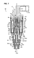
- Fig. 7 is a longitudinal cross sectional view for illustrating the fourth embodiment of a control valve for a variable displacement compressor according to the present invention.
- control valve 1D of the fourth embodiment in Fig. 7 the same reference numerals are given to the similar constitution and function parts to those of the control valve 1A of the above-described first embodiment and the descriptions are omitted. The different parts will be mainly described hereinafter.
- a valve rod 15 is divided into an upper part 15B' and a lower part 15A', where the upper part 15B' is from an upper end part 15b to the upper side of a locking part for forcedly moving 70 and the lower part 15A' is the lower side than the upper part 15B'.
- a lower end face of the upper part 15B' oppositely contacts to an upper end face of the lower part 15A'.
Landscapes
- Engineering & Computer Science (AREA)
- Mechanical Engineering (AREA)
- General Engineering & Computer Science (AREA)
- Compressors, Vaccum Pumps And Other Relevant Systems (AREA)
- Control Of Positive-Displacement Pumps (AREA)
- Magnetically Actuated Valves (AREA)
Abstract
Description
- The present invention relates to a control valve for a variable displacement compressor used for a car air-conditioner and the like, and more particularly, to a control valve for a variable displacement compressor capable of hardly causing operation failure of a valve rod.
- Generally in a conventional control valve for a variable displacement compressor used for a car air-conditioner and the like, refrigerant having discharge pressure Pd is introduced from a compressor (a discharge chamber of a compressor) and is throttled so as to be introduced to a crank chamber, in order to adjust a pressure Pc in the crank chamber of the compressor. An introducing amount (a throttling amount) into the crank chamber is controlled corresponding to a suction pressure Ps of the compressor. As for the basic constitution of the control valve, as described in Japanese Patent Application Laid Open
No. 2003-172256 - In the conventional control valve having such the constitution, when the electric current is applied to the coil of the electromagnetic actuator, the plunger is attracted to the attraction piece. Then, the valve rod is moved in the valve closing direction following the plunger by energizing force of the valve closing spring. On the other hand, refrigerant having a suction pressure Ps introduced from a compressor to a suction pressure introducing inlet is introduced into the pressure sensing chamber from an introduction chamber through a clearance formed between the plunger and a guiding pipe arranged on the outer periphery of the plunger. The pressure sensitive response member (for example, a bellows device) is displaced so as to extend or contract corresponding to the pressure (the suction pressure Ps) in the pressure sensing chamber (the member contracts when the suction pressure Ps is high, and extends when the suction pressure Ps is low). The displacement (pressing force) is transmitted to the valve rod, so as to control a valve opening. The valve opening is determined by the attracting force of the attraction piece to the plunger, the pressing force of the pressure sensitive response member, and the energizing forces of a plunger spring (a valve opening spring) and a valve closing spring. Corresponding to the valve opening, the introducing amount (the throttling amount) into the outlet side, that is, into the crank chamber, of the refrigerant having a discharge pressure introduced into the valve chamber from the discharge pressure refrigerant inlet, is adjusted, so as to control the pressure Pc in the crank chamber.
- However, the above-described control valve has the constitution in which the valve rod moves in the valve closing direction by only the energizing force of the valve closing spring. So, the operation failure of locking of the valve rod or the like is caused when a foreign matter is clogged between sliding faces of the valve rod and the guiding hole or the sliding resistance of the valve rod is increased by oil seizing or the like. For example, there is a problem that even when the plunger is attracted by the attraction piece, the valve rod does not move in the valve closing direction so as to be inactive. In such case, the valve opening is not properly controlled. In order to solve such the operation failure, the energizing force of the valve closing spring may be increased. However, if the energizing force is increased, the energizing force of the plunger spring (the valve opening spring) must be also increased. As a result of this, the sizes of springs and a product are increased, so that the cost is increased.
- So, in order to solve the problems,
Japanese Patent Application Laid Open No. 2004-100473 - However, the above-described control valve in which the plunger and the valve rod are directly connected has the following problems.
- When electric current is applied, the plunger may move upwardly and downwardly (in the valve opening and closing directions) while being laterally deviated (moved to one side) or inclined depending on a magnetic circuit (due to the concentricity of the attraction piece and the plunger). Thereby, if the plunger and the valve rod are connected without a backlash, the valve rod is pushed to the guiding hole according to the deviation or inclination of the plunger so as to increase sliding resistance. As a result, the valve rod and the plunger do not smoothly move, so as to cause operation failure such as locking, which is similar to the above-described problem.
- Further, when the plunger and the valve rod are directly connected, the size management and assembling accuracy of parts are hardly achieved due to the above-described problem, and the cost may be increased.
- The present invention is made to solve the above-described problems, an objective of the present invention is to provide a control valve for a variable displacement compressor capable of hardly causing operation failure of a valve rod without increasing the cost and size.
- In order to realize the above-described objective, a control valve for a variable displacement compressor according to the present invention basically comprises a valve rod having a valve body part; a valve main body including a guiding hole in which the valve rod is slidably and fitly inserted, a valve chamber having a valve port to/from which the valve body part contacts/separates, a discharge pressure refrigerant inlet provided at the upstream side than the valve port for introducing refrigerant having discharge pressure from a compressor, and a refrigerant outlet provided at the downstream side than the valve port so as to communicate with a crank chamber of the compressor; an electromagnetic actuator having a plunger for moving the valve rod in the valve closing direction; a pressure sensing chamber in which a suction pressure is introduced from the compressor; and a pressure sensitive response member for pressing the valve rod in the valve opening direction corresponding to the pressure of the pressure sensing chamber, wherein, although the valve rod is forcedly moved in the valve closing direction by the plunger, the valve rod is fitted to the plunger having a predetermined diametrical directional clearance so as not to be influenced by lateral deviation and inclination of the plunger.
- As for a more preferable aspect of the control valve, a control valve comprises a valve rod having a valve body part; a valve main body including a guiding hole in which the valve rod is slidably and fitly inserted, a valve chamber having a valve port to/from which the valve body part contacts/separates, a discharge pressure refrigerant inlet provided at the upstream side than the valve port for introducing refrigerant having discharge pressure from a compressor, and a refrigerant outlet provided at the downstream side than the valve port so as to communicate with a crank chamber of the compressor; an electromagnetic actuator having a coil, a cylindrical stator arranged at the inner periphery side of the coil, an attraction piece fixed to the stator, a plunger arranged at the lower side than the attraction piece so as to be upwardly and downwardly slidable, a plunger spring arranged between the attraction piece and the plunger, and a guiding pipe in which the plunger is slidably and fitly inserted; a pressure sensing chamber formed at the upper side than the attraction piece, in which a suction pressure is introduced from the compressor; and a pressure sensitive response member for pressing the valve rod in the valve opening direction corresponding to the pressure of the pressure sensing chamber, wherein, although the valve rod is forcedly moved in the valve closing direction by the plunger when the plunger is attracted by the attraction piece, the valve rod is fitted to the plunger having a predetermined diametrical directional clearance so as not to be influenced by lateral deviation and inclination of the plunger.
- In a preferable aspect, the plunger has an inserting hole in which an upper part of the valve rod is fitly inserted, and a locking part for forcedlymoving is provided at the upper side than the inserting hole of the valve rod. Further, a clearance formed between the valve rod and the inserting hole is made larger than a clearance formed between the plunger and the guiding pipe arranged around the outer periphery of the plunger.
- In this case, the locking part for forcedly moving is preferably formed with an annular member, which is externally fitted to the valve rod to be caulked and fixed.
- As for another preferable aspect, a small diameter part is provided at the valve rod, a large diameter part as the locking part for forcedly moving is provided at the upper side of the small diameter part, and a center hole in which the small diameter part is fitly inserted is provided at the center of the plunger. In order to easily assemble these parts, an eccentric hole capable of inserting the large diameter part is provided so as to have an eccentricity of a predetermined distance in the diametrical direction and to partially overlap with the center hole. The clearance formed between the small diameter part and the center hole is made larger than the clearance formed between the plunger and the guiding pipe arranged around the outer periphery of the plunger.
- As for another preferable aspect, the valve rod is divided into an upper part and a lower part, where the upper part is from an upper end part contacting to the pressure sensitive response member to the upper side of the locking part for forcedly moving, and the lower part is the lower side than the upper part. A lower end face of the upper part oppositely contacts to an upper end face of the lower part.
- In the control valve for a variable displacement compressor according to the present invention, for example, the plunger has the inserting hole for fitly inserting an intermediate part of the valve rod, and the locking part for forcedly moving is provided at the upper side than the inserting hole in the valve rod. Further, the clearance formed between the valve rod and the inserting hole is made larger than the clearance formed between the plunger and the guiding pipe arranged around the outer periphery of the plunger. Then, although the valve rod is forcedly moved in the valve closing direction by the plunger, the valve rod is fitted to the plunger having a predetermined diametrical directional clearance so as not to be influenced from the lateral deviation and inclination of the plunger. So, even when the plunger is laterally deviated or inclined, the valve rod is not pushed to the guiding hole. Therefore, the sliding resistance of the valve rod is not increased and, as a result of this, the operation failure of the valve rod is hardly caused.
- Further, the size management and assembling accuracy of parts may be carried out not so rigidly (those may be carried out like a conventional control valve in which a plunger and a valve rod are not directly connected). In addition, since it is not necessary to increase the size of a valve closing spring, the cost increase can be restricted to the minimum.
-
- Fig. 1 is a longitudinal cross sectional view for illustrating a first embodiment of a control valve for a variable displacement compressor according to the present invention.
- Figs. 2A and 2B are views for illustrating a plunger in Fig. 1 and its vicinity, where Fig. 2A is an enlarged longitudinal cross sectional view, and Fig. 2B is a cross sectional view taken along the arrow B-B in Fig. 2A.
- Fig. 3 is a longitudinal cross sectional view for illustrating a second embodiment of a control valve for a variable displacement compressor according to the present invention.
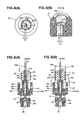
- Figs. 4A and 4B are views for illustrating a plunger in Fig. 3, where Fig. 4A is an enlarged plane view, and Fig. 4B is an enlarged cutout perspective view.
- Fig. 5 is a view for explaining an assembling processing of a control valve illustrated in Fig. 3.
- Fig. 6 is a longitudinal cross sectional view for illustrating a third embodiment of a control valve for a variable displacement compressor according to the present invention.
- Fig. 7 is a longitudinal cross sectional view for illustrating a fourth embodiment of a control valve for a variable displacement compressor according to the present invention.
- Hereinafter, embodiments of a control valve for a variable displacement compressor of the present invention will be described with drawings. Fig. 1 is a longitudinal cross sectional view for illustrating the first embodiment of a control valve for a variable displacement compressor according to the present invention.
- In Fig. 1, a
control valve 1A includes avalve rod 15 having avalve body part 15a, and a valvemain body 20. The valvemain body 20 includes avalve chamber 21 having a valve seat (a valve port) 22 to/from which thevalve body part 15a contacts/separates, a discharge pressurerefrigerant introducing inlet 25 with a plurality offilters 25A provided at an outer periphery side of the valve chamber 21 (at the upstream side than the valve seat 22) for introducing a refrigerant having a discharge pressure Pd from a compressor, and arefrigerant outlet 26 provided at a lower part (at the downstream side) of thevalve seat 22 so as to communicate with a crank chamber of the compressor. Further, thecontrol valve 1A also includes anelectromagnetic actuator 30. - The
electromagnetic actuator 30 comprises acoil 32 for exciting by electric current, aconnector head 31 having a powersource connector part 31A mounted on the upper side of thecoil 32, acylindrical stator 33 arranged at the inner periphery side of thecoil 32, anattraction piece 34 having a recess shaped cross section which is pressed-in and fixed at the inner periphery of a lower end part of thestator 33, a guidingpipe 35 having a flange shaped part, of which a top end part is connected with the outer periphery of the lower end part (a stepped part) of thestator 33 by TIG welding, aplunger 37 which is arranged at a lower side than theattraction piece 34 and at the inner periphery side of the guidingpipe 35 so as to be upwardly and downwardly slidable, and a cylindrical steppedhousing 60 which is externally fitted on thecoil 32 and theconnector head 31. - An annular groove for sealing 75 is formed at the outer periphery part of the
connector head 31, and an O-ring 66 as a sealing member is mounted in the annular groove for sealing 75 while being compressed toward the inner side in the radial direction by thehousing 60. - Further, an annular groove for
caulking 76 is formed at the upper side than the annular groove for sealing 75 in the outer periphery part of theconnector head 31, and an upper end part (a caulked part) of thehousing 60 is pushed into the annular groove forcaulking 76 to be caulked and fixed. - An adjust
screw 65 having a hexagonal hole is screwed to an upper part of thestator 33, and apressure sensing chamber 45, in which suction pressure Ps of a compressor is introduced, is formed between the adjustscrew 65 and theattraction piece 34 at the inner periphery side of thestator 33. Thepressure sensing chamber 45 has a bellowsmain body 40, as a pressure sensitive response member, including abellows 41, an downwardly-projectedupper stopper 42, an upwardly-recessedlower stopper 43, and acompression coil spring 44. Further, acompression coil spring 46 for energizing in the direction of contracting the bellows main body 40 (the direction of contracting toward the adjustscrew 65 side) is arranged between the bellowsmain body 40 and theattraction piece 34. Furthermore, anupper end part 15b of thevalve rod 15 is inserted into (the upwardly recessed part of) thelower stopper 43 of the bellowsmain body 40 so as to contact thereto, and a plunger spring (a valve opening spring) 47 including a compression coil spring for energizing thevalve rod 15 in the lower direction (the valve opening direction) is arranged between theattraction piece 34 and a recessedpart 37b (a locking part for forcedly moving 70 arranged therein) of theplunger 37. - On the other hand, the valve
main body 20 has a projectedstopper part 28 at the center of an upper part thereof for controlling the lowermost descending position of theplunger 37, and an guidinghole 19, in which thevalve rod 15 is slidably and fitly inserted, is formed at a center portion of an upper side than the valve chamber including the projectedstopper part 28. Further, a suction pressurerefrigerant introducing chamber 23, in which refrigerant having suction pressure of a compressor is introduced, is formed between theplunger 37 and the outer periphery of an upper part of the valve main body 20 (the outer periphery of the projected stopper part 28), and a plurality of suction pressure refrigerant introducinginlets 27 is formed at the outer periphery side of thechamber 23. The refrigerant having suction pressure Ps introduced from the suction pressure refrigerant introducinginlets 27 into the suction pressurerefrigerant introducing chamber 23 is introduced into thepressure sensing chamber 45 throughvertical grooves plunger 37, and acommunication hole 39 formed at theattraction piece 34. - The valve
main body 20 has avalve closing spring 48 at a lower part (the refrigerant outlet 26) thereof, where thevalve closing spring 48 is constituted of a conical compression coil spring for upwardly energizing thevalve rod 15. - Further, a lower end part of the
pipe 35 is internally fitted to the inner periphery of aholder 50, and is connected and fixed by brazing. Further, a lower partsmall diameter part 61 of thehousing 60 is press-fitted on the outer periphery of theholder 50, and a lower part of theholder 50 has a cylindrical part with athin flange 50a, which is externally fitted to an upper part outer periphery of the valvemain body 20. By subjecting the cylindrical part with athin flange 50a to peel caulking processing, theholder 50 is fixed to the valvemain body 20. - In addition to the above-described constitution, in this embodiment, when the
plunger 37 is attracted by the attraction piece 34 (when electric current is applied), thevalve rod 15 is forcedly pulled in the closing direction by theplunger 37. However, thevalve rod 15 is not influenced from lateral deviation or inclination of theplunger 37. - More particularly, as illustrated in Figs. 2A and 2B, the
plunger 37 has an insertinghole 37c, in which a lowerlarge diameter part 15A of thevalve rod 15 is fitly inserted, in addition to the recessedpart 37b. Further, theplunger 37 also has a locking part for forcedly moving 70 at the upper side than the insertinghole 37c in thevalve rod 15, where the lockingpart 70 has a larger outer diameter than the diameter of the insertinghole 37c. The locking part for forcedly moving 70 is constituted of an annular member which is externally fitted to the small diameterupper part 15B of thevalve rod 15, and caulked fixedly (a caulked part 72). - Further, a clearance β (the maximum clearance) formed between the locking part for forcedly moving 70 and the inner periphery face of the recessed
part 37b of theplunger 37, and a clearance γ (the maximum clearance) formed between the valve rod 15 (the lowerlarge diameter part 15A) and the insertinghole 37c are made larger than a clearance α (the maximum clearance) formed between theplunger 37 and the guidingpipe 35 arranged around the outer periphery of theplunger 37. - In this case, α, β and γ are as follows.
- α: (Inner diameter Da of the guiding pipe 35) - (Outer diameter Db of the plunger 37) = about 20µm
- β: (Inner diameter Dc of the recessed
part 37b) - (Outer diameter Dd of the locking part for forcedly moving 70) = about 40µm - γ: (Inner diameter De of the inserting
hole 37c) - (Outer diameter Df of the lowerlarge diameter part 15A of the valve rod) = about 40µm - In addition, the clearance formed between the lower
large diameter part 15A of thevalve rod 15 and the guidinghole 19 is made fairly smaller (about 10µm) than the clearances α, β and γ, in order to suppress leaking of a refrigerant from thevalve chamber 21 to the suction pressurerefrigerant introduction chamber 23 as much as possible. - In the
control valve 1A having the above-described constitution, when theplunger 37 is attracted by the attraction piece 34 (when electric current is applied), thevalve rod 15 is pushed up in the valve closing direction by the energizing force of thevalve closing spring 48, and the locking part for forcedly moving 70 is locked to theplunger 37. So, thevalve rod 15 is forcedly pulled in the valve closing direction by theplunger 37. On the other hand, the refrigerant having the suction pressure Ps introduced into the suctionpressure introducing inlet 27 from the compressor is introduced into thepressure sensing chamber 45 from the introducingchamber 23 through thevertical grooves plunger 37 and thecommunication hole 39 formed at theattraction piece 34. The bellows main body 40 (the inside of which has a vacuum pressure) is displaced by extending or contracting corresponding to the pressure (the suction pressure Ps) in the pressure sensing chamber 45 (where the bellowsmain body 40 contracts when the suction pressure Ps is high, and extends when the suction pressure Ps is low), and the displacement is transmitted to thevalve rod 15 so as to control a valve opening. That is, the valve opening is determined by the attracting force of theattraction piece 34 to theplunger 37, the pressing force of the bellowsmain body 40, and the energizing forces of the plunger spring (the valve opening spring) 47 and thevalve closing spring 48. Corresponding to the valve opening, the introducing amount (the throttling amount) of the refrigerant having the discharge pressure Pd, which is introduced into thevalve chamber 21 from the discharge pressurerefrigerant introducing inlet 25, into theoutlet 26 side, that is, into the crank chamber is adjusted so as to control the pressure Pc in the crank chamber. - Further, in this embodiment, the inserting
hole 37c, in which the lowerlarge diameter part 15A of thevalve rod 15 is inserted fitly, is provided in theplunger 37, and the locking part for forcedly moving 70 is provided on thevalve rod 15 at the upper side than the insertinghole 37c. Further, the clearance β (the maximum clearance) formed between the locking part for forcedly moving 70 and the inner periphery face of the recessedpart 37b of theplunger 37, and the clearance γ (the maximum clearance) formed between the valve rod 15 (the lowerlarge diameter part 15A) and the insertinghole 37c are made larger than the clearance α (the maximum clearance) formed between theplunger 37 and the guidingpipe 35 arranged around the outer periphery of theplunger 37. Thereby, although thevalve rod 15 is forcedly moved in the valve closing direction by theplunger 37, thevalve rod 15 is not influenced from the lateral deviation and inclination of theplunger 37. So, even when theplunger 37 is laterally deviated or inclined, thevalve rod 15 is not pushed to the guidinghole 19. Therefore, the sliding resistance of thevalve rod 15 is not increased and, as a result of this, the operation failure of thevalve rod 15 is hardly caused. - Further, the size management and assembling accuracy of parts may be carried out not so rigidly (those may be carried out like a conventional control valve in which a plunger and a valve rod are not directly connected). In addition, since it is not necessary to increase the size of a valve closing spring, the cost increase can be restricted to the minimum.
- Fig. 3 is a longitudinal cross sectional view for illustrating the second embodiment of a control valve for a variable displacement compressor according to the present invention.
- In a
control valve 1B of the second embodiment in Figs. 2A and 2B, the same reference numerals are given to the similar constitution and function parts to those of thecontrol valve 1A of the above-described first embodiment and the descriptions are omitted. The different parts will be mainly described hereinafter. - In the
control valve 1B of the second embodiment, an intermediatesmall diameter part 15C is provided at thevalve rod 15, and alarge diameter part 80 to be the locking part for forcedly moving is provided at the upper side of thesmall diameter part 15c. On the other hand, as illustrated in Fig. 4, a smalldiameter center hole 37f (a center line Oa), in which thesmall diameter part 15C is fitly inserted, is provided at the center of theplunger 37. Further, in order to easily assemble these parts, a large diametereccentric hole 37e (a center line Oe) capable of inserting the large diameter part (the locking part for forcedly moving) 80 is provided so as to have an eccentricity of a predetermined distance Le in the diametrical direction and to partially overlap with the smalldiameter center hole 37f. In this case, the diameters of thecenter hole 37f and theeccentric hole 37e, and the center distance Le between those, are set so as not to detach theplunger 37 from thevalve rod 15 even when theplunger 37 is laterally deviated or inclined. - Further, the clearance (the maximum clearance) formed between the valve rod 15 (the intermediate
small diameter part 15c thereof) and the smalldiameter center hole 37f is made larger than the clearance (the maximum clearance) formed between theplunger 37 and the guidingpipe 35 arranged around the outer periphery of theplunger 37, like the first embodiment. - Further, when the
plunger 37 is assembled with the other parts, theplunger 37 is dropped along thevalve rod 15 so as to pass the large diameter part (the locking part for forcedly moving) 80 through theeccentric hole 37e, as illustrated in Fig. 5A. Then, theplunger 37 is laterally moved so as to fitly insert the intermediatesmall diameter part 15C into the smalldiameter center hole 37f, as illustrated in Fig. 5B. Then, the guidingpipe 35 and the like are mounted. - In the
control valve 1B of this embodiment having such the constitution, the approximately similar operation effect to that of the first embodiment can be obtained. Further, since the caulking processing or the like in the first embodiment is not necessary, the cost for assembling the parts can be restricted. - Fig. 6 is a longitudinal cross sectional view for illustrating the third embodiment of a control valve for a variable displacement compressor according to the present invention.
- In a
control valve 1C of the third embodiment in Fig. 6, the same reference numerals are given to the similar constitution and function parts to those of thecontrol valve 1B of the above-described second embodiment and the descriptions are omitted. The different parts will be mainly described hereinafter. - In the
control valve 1C of the third embodiment, a large diameter part (a locking part for forcedly moving) 80' is made shorter than that of the second embodiment, and is placed at a little lower position than that of the second embodiment. Avalve rod 15 is divided into anupper part 15B' and alower part 15A', where theupper part 15B' is from anupper end part 15b (which is inserted and contacted to thelower stopper 43 of the bellows main body 40) to the upper side of the large diameter part (the locking part for forcedly moving) 80', and thelower part 15A' is the lower side than theupper part 15B'. A lower end face of theupper part 15B' oppositely contacts to an upper end face of thelower part 15A'. - By having such the constitution, even when a bellows
main body 40 undesirably operates such as laterally deviating or inclining, for example, thelower part 15A' (thevalve body part 15a) of thevalve rod 15 is not influenced from such operation. - Fig. 7 is a longitudinal cross sectional view for illustrating the fourth embodiment of a control valve for a variable displacement compressor according to the present invention.
- In a
control valve 1D of the fourth embodiment in Fig. 7, the same reference numerals are given to the similar constitution and function parts to those of thecontrol valve 1A of the above-described first embodiment and the descriptions are omitted. The different parts will be mainly described hereinafter. - In a
control valve 1D in the fourth embodiment, avalve rod 15 is divided into anupper part 15B' and alower part 15A', where theupper part 15B' is from anupper end part 15b to the upper side of a locking part for forcedly moving 70 and thelower part 15A' is the lower side than theupper part 15B'. A lower end face of theupper part 15B' oppositely contacts to an upper end face of thelower part 15A'. - By having such the constitution, even when a bellows
main body 40 undesirably operates such as laterally deviating or inclining, for example, thelower part 15A' (thevalve body part 15a) of thevalve rod 15 is not influenced from such operation.
Claims (6)
- A control valve for a variable displacement compressor comprising:a valve rod having a valve body part;a valve main body including a guiding hole in which the valve rod is slidably and fitly inserted, a valve chamber having a valve port to/from which the valve body part contacts/separates, a discharge pressure refrigerant inlet provided at the upstream side than the valve port for introducing refrigerant having discharge pressure from a compressor, and a refrigerant outlet provided at the downstream side than the valve port so as to communicate with a crank chamber of the compressor;an electromagnetic actuator having a plunger for moving the valve rod in the valve closing direction;a pressure sensing chamber in which a suction pressure is introduced from the compressor; anda pressure sensitive response member for pressing the valve rod in the valve opening direction corresponding to the pressure of the pressure sensing chamber,wherein, although the valve rod is forcedly moved in the valve closing direction by the plunger, the valve rod is fitted to the plunger having a predetermined diametrical directional clearance so as not to be influenced by lateral deviation and inclination of the, plunger.
- A control valve for a variable displacement compressor comprising:a valve rod having a valve body part;a valve main body including a guiding hole in which the valve rod is slidably and fitly inserted, a valve chamber having a valve port to/from which the valve body part contacts/separates, a discharge pressure refrigerant inlet provided at the upstream side than the valve port for introducing refrigerant having a discharge pressure from a compressor, and a refrigerant outlet provided at the downstream side than the valve port so as to communicate with a crank chamber of the compressor;an electromagnetic actuator having a coil, a cylindrical stator arranged at the inner periphery side of the coil, an attraction piece fixed to the stator, a plunger arranged at the lower side than the attraction piece so as to upwardly and downwardly slidable, a plunger spring arranged between the attraction piece and the plunger, and a guiding pipe in which the plunger is slidably and fitly inserted;a pressure sensing chamber formed at the upper side than the attraction piece, in which a suction pressure is introduced from the compressor; anda pressure sensitive response member for pressing the valve rod in the valve opening direction corresponding to the pressure of the pressure sensing chamber,wherein, although the valve rod is forcedly pulled in the valve closing direction by the plunger when the plunger is attracted by the attraction piece, the valve rod is fitted to the plunger having a predetermined diametrical directional clearance so as not to be influenced by lateral deviation and inclination of the plunger.
- The control valve for a variable displacement compressor as claimed in claim 1 or 2,
wherein the plunger has an inserting hole, in which a middle part of the valve rod is fitly inserted;
a locking part for forcedly moving is provided at the upper side than the inserting hole of the valve rod; and
a clearance formed between the valve rod and the inserting hole is made larger than a clearance formed between the plunger and the guiding pipe arranged around the outer periphery of the plunger. - The control valve for a variable displacement compressor as claimed in claim 3,
wherein the locking part for forcedly moving is formed with an annular member which is externally fitted to the valve rod to be caulked and fixed. - The control valve for a variable displacement compressor as claimed in claim 1 or 2,
wherein a small diameter part is provided at the valve rod,
a large diameter part to be as the locking part for forcedly moving is provided at the upper side of the small diameter part,
a center hole in which the small diameter part is fitly inserted is provided at the center of the plunger,
an eccentric hole capable of inserting the large diameter part is provided so as to have an eccentricity of a predetermined distance in the diametrical direction and to partially overlap with the center hole in order to easily assemble the above-described parts, and
a clearance formed between the small diameter part and the center hole is made larger than a clearance formed between the plunger and the guiding pipe arranged around the outer periphery of the plunger. - The control valve for a variable displacement compressor as claimed in any one of claims 3 to 5,
wherein the valve rod is divided into an upper part and a lower part, where the upper part is from an upper end part contacting to the pressure sensitive response member to the upper side of the locking part for forcedly moving, and the lower part is the lower side than the upper part, and
a lower end face of the upper part oppositely contacts to an upper end face of the lower part.
Applications Claiming Priority (1)
| Application Number | Priority Date | Filing Date | Title |
|---|---|---|---|
| JP2006111055A JP4714626B2 (en) | 2006-04-13 | 2006-04-13 | Control valve for variable displacement compressor |
Publications (3)
| Publication Number | Publication Date |
|---|---|
| EP1845260A2 true EP1845260A2 (en) | 2007-10-17 |
| EP1845260A3 EP1845260A3 (en) | 2009-08-26 |
| EP1845260B1 EP1845260B1 (en) | 2010-05-12 |
Family
ID=38180329
Family Applications (1)
| Application Number | Title | Priority Date | Filing Date |
|---|---|---|---|
| EP07007321A Ceased EP1845260B1 (en) | 2006-04-13 | 2007-04-10 | Control valve for variable displacement compressor |
Country Status (5)
| Country | Link |
|---|---|
| US (1) | US7690898B2 (en) |
| EP (1) | EP1845260B1 (en) |
| JP (1) | JP4714626B2 (en) |
| CN (1) | CN101054965B (en) |
| DE (1) | DE602007006365D1 (en) |
Cited By (1)
| Publication number | Priority date | Publication date | Assignee | Title |
|---|---|---|---|---|
| EP3187730A1 (en) * | 2015-12-16 | 2017-07-05 | Fujikoki Corporation | Variable-capacity compressor control valve |
Families Citing this family (9)
| Publication number | Priority date | Publication date | Assignee | Title |
|---|---|---|---|---|
| WO2009009640A1 (en) * | 2007-07-10 | 2009-01-15 | Continental Automotive Systems Us, Inc. | Idle air control valve |
| US9114397B2 (en) * | 2007-10-25 | 2015-08-25 | Canon U.S. Life Sciences, Inc. | Method of reducing cross-contamination in continuous amplification reactions in a channel |
| JP2012026311A (en) | 2010-07-21 | 2012-02-09 | Fuji Koki Corp | Control valve for variable displacement compressor |
| CN102454797B (en) * | 2010-10-26 | 2013-02-20 | 浙江三花股份有限公司 | Electromagnetic expansion valve |
| JP6600603B2 (en) * | 2016-06-28 | 2019-10-30 | 株式会社不二工機 | Control valve for variable displacement compressor and assembly method thereof |
| JP6632503B2 (en) * | 2016-09-30 | 2020-01-22 | 株式会社不二工機 | Control valve for variable displacement compressor |
| KR102896044B1 (en) * | 2018-01-29 | 2025-12-05 | 한온시스템 주식회사 | Control system for a compressor, electronic control valve for the same, and compressor with the same |
| CN116816951A (en) * | 2021-07-05 | 2023-09-29 | 广东威灵电机制造有限公司 | Electronic expansion valve and refrigeration equipment |
| CN114135458A (en) * | 2021-11-30 | 2022-03-04 | 力源液压(苏州)有限公司 | Constant power control structure of plunger pump |
Family Cites Families (23)
| Publication number | Priority date | Publication date | Assignee | Title |
|---|---|---|---|---|
| DE3938896A1 (en) * | 1989-11-24 | 1991-05-29 | Pierburg Gmbh | Electromagnetic control valve with valve seat - has spring=loaded valve element protruding through axial bore in core with core stop collar on valve element |
| EP0536989B1 (en) * | 1991-10-07 | 1995-05-03 | Sanden Corporation | Slant plate type compressor with variable capacity control mechanism |
| KR100225196B1 (en) * | 1991-10-07 | 1999-10-15 | 우시구보 마사요시 | Slant plate type compressor with variable capacity control mechanism |
| JP3479353B2 (en) * | 1994-10-17 | 2003-12-15 | 株式会社ケーヒン | Exhaust gas recirculation valve |
| JP3550238B2 (en) * | 1995-12-27 | 2004-08-04 | 株式会社鷺宮製作所 | solenoid valve |
| JPH10318414A (en) * | 1997-05-20 | 1998-12-04 | Toyota Autom Loom Works Ltd | Solenoid control valve |
| JP3728387B2 (en) * | 1998-04-27 | 2005-12-21 | 株式会社豊田自動織機 | Control valve |
| JP2002122070A (en) * | 2000-10-17 | 2002-04-26 | Fuji Koki Corp | Control valve for variable displacement compressor |
| JP4829419B2 (en) * | 2001-04-06 | 2011-12-07 | 株式会社不二工機 | Control valve for variable displacement compressor |
| JP2002332962A (en) * | 2001-05-10 | 2002-11-22 | Toyota Industries Corp | Control valve for variable displacement compressor |
| JP3461343B2 (en) | 2001-11-30 | 2003-10-27 | 株式会社不二工機 | Control valve for variable displacement compressor |
| KR100858604B1 (en) * | 2001-11-30 | 2008-09-17 | 가부시기가이샤 후지고오키 | Control Valve for Variable Capacity Compressors |
| JP4031945B2 (en) * | 2002-04-09 | 2008-01-09 | サンデン株式会社 | Volume control valve for variable capacity compressor |
| JP4173980B2 (en) | 2002-09-05 | 2008-10-29 | 株式会社不二工機 | Control valve for variable capacity compressor |
| JP4422512B2 (en) * | 2003-04-09 | 2010-02-24 | 株式会社不二工機 | Control valve for variable capacity compressor |
| JP4316955B2 (en) * | 2003-08-11 | 2009-08-19 | イーグル工業株式会社 | Capacity control valve |
| JP4456906B2 (en) * | 2004-03-25 | 2010-04-28 | 株式会社不二工機 | Control valve for variable capacity compressor |
| US6918571B1 (en) * | 2004-11-18 | 2005-07-19 | Eaton Corporation | Solenoid operated valve assembly and method of making same |
| JP2006189115A (en) * | 2005-01-07 | 2006-07-20 | Tgk Co Ltd | Control valve attachment structure |
| JP2006194175A (en) * | 2005-01-14 | 2006-07-27 | Tgk Co Ltd | Control valve for variable displacement compressor |
| JP4545031B2 (en) * | 2005-03-31 | 2010-09-15 | 株式会社鷺宮製作所 | Control valve, variable capacity compressor and refrigeration cycle apparatus |
| JP4504243B2 (en) * | 2005-04-12 | 2010-07-14 | 株式会社不二工機 | Control valve for variable displacement compressor |
| JP4728848B2 (en) * | 2006-03-15 | 2011-07-20 | 株式会社鷺宮製作所 | Control valve, variable capacity compressor and refrigeration cycle apparatus |
-
2006
- 2006-04-13 JP JP2006111055A patent/JP4714626B2/en not_active Expired - Fee Related
-
2007
- 2007-04-06 US US11/784,344 patent/US7690898B2/en not_active Expired - Fee Related
- 2007-04-10 EP EP07007321A patent/EP1845260B1/en not_active Ceased
- 2007-04-10 DE DE602007006365T patent/DE602007006365D1/en active Active
- 2007-04-12 CN CN2007100971871A patent/CN101054965B/en not_active Expired - Fee Related
Cited By (1)
| Publication number | Priority date | Publication date | Assignee | Title |
|---|---|---|---|---|
| EP3187730A1 (en) * | 2015-12-16 | 2017-07-05 | Fujikoki Corporation | Variable-capacity compressor control valve |
Also Published As
| Publication number | Publication date |
|---|---|
| DE602007006365D1 (en) | 2010-06-24 |
| US20070243076A1 (en) | 2007-10-18 |
| CN101054965B (en) | 2011-04-20 |
| CN101054965A (en) | 2007-10-17 |
| JP2007285159A (en) | 2007-11-01 |
| EP1845260A3 (en) | 2009-08-26 |
| US7690898B2 (en) | 2010-04-06 |
| JP4714626B2 (en) | 2011-06-29 |
| EP1845260B1 (en) | 2010-05-12 |
Similar Documents
| Publication | Publication Date | Title |
|---|---|---|
| EP1845260B1 (en) | Control valve for variable displacement compressor | |
| EP3239570B1 (en) | Volume control valve | |
| CN114001163B (en) | Variable capacity compressor control valve | |
| EP3835578B1 (en) | Capacity control valve | |
| CN1646808A (en) | Variable displacement compressor | |
| US7381031B2 (en) | Control valve for variable displacement compressor | |
| CN109715943B (en) | Control valve for variable capacity compressor | |
| US6302656B1 (en) | Solenoid controlled valve and variable displacement compressor | |
| JP2010185285A (en) | Control valve | |
| US20040086391A1 (en) | Control valve for variable displacement compressor | |
| JPWO2019142931A1 (en) | Capacity control valve | |
| KR100498156B1 (en) | Proportional solenoid valve | |
| JP2008298013A (en) | Control valve for variable displacement compressor and its manufacturing process | |
| US7387501B2 (en) | Control valve for variable displacement compressor | |
| EP2410220A2 (en) | Control valve for variable displacement compressor | |
| JP2004137980A (en) | Displacement control valve for variable displacement compressor | |
| US7437881B2 (en) | Control valve for variable displacement compressor | |
| CN109416035B (en) | Control valve for variable displacement compressor | |
| CN115427717A (en) | Capacity control valve | |
| US12012948B2 (en) | Capacity control valve | |
| EP3835576B1 (en) | Capacity control valve | |
| KR20210142188A (en) | capacity control valve | |
| JP2020169573A (en) | Control valve for variable capacity-type compressor | |
| JP2008297974A (en) | Control valve for variable displacement compressor | |
| JP5269391B2 (en) | Control valve for variable displacement compressor |
Legal Events
| Date | Code | Title | Description |
|---|---|---|---|
| PUAI | Public reference made under article 153(3) epc to a published international application that has entered the european phase |
Free format text: ORIGINAL CODE: 0009012 |
|
| AK | Designated contracting states |
Kind code of ref document: A2 Designated state(s): AT BE BG CH CY CZ DE DK EE ES FI FR GB GR HU IE IS IT LI LT LU LV MC MT NL PL PT RO SE SI SK TR |
|
| AX | Request for extension of the european patent |
Extension state: AL BA HR MK YU |
|
| PUAL | Search report despatched |
Free format text: ORIGINAL CODE: 0009013 |
|
| AK | Designated contracting states |
Kind code of ref document: A3 Designated state(s): AT BE BG CH CY CZ DE DK EE ES FI FR GB GR HU IE IS IT LI LT LU LV MC MT NL PL PT RO SE SI SK TR |
|
| AX | Request for extension of the european patent |
Extension state: AL BA HR MK RS |
|
| GRAP | Despatch of communication of intention to grant a patent |
Free format text: ORIGINAL CODE: EPIDOSNIGR1 |
|
| 17P | Request for examination filed |
Effective date: 20091216 |
|
| GRAS | Grant fee paid |
Free format text: ORIGINAL CODE: EPIDOSNIGR3 |
|
| GRAA | (expected) grant |
Free format text: ORIGINAL CODE: 0009210 |
|
| AK | Designated contracting states |
Kind code of ref document: B1 Designated state(s): DE FR GB IT |
|
| REG | Reference to a national code |
Ref country code: GB Ref legal event code: FG4D |
|
| REF | Corresponds to: |
Ref document number: 602007006365 Country of ref document: DE Date of ref document: 20100624 Kind code of ref document: P |
|
| PLBE | No opposition filed within time limit |
Free format text: ORIGINAL CODE: 0009261 |
|
| STAA | Information on the status of an ep patent application or granted ep patent |
Free format text: STATUS: NO OPPOSITION FILED WITHIN TIME LIMIT |
|
| 26N | No opposition filed |
Effective date: 20110215 |
|
| REG | Reference to a national code |
Ref country code: DE Ref legal event code: R097 Ref document number: 602007006365 Country of ref document: DE Effective date: 20110214 |
|
| REG | Reference to a national code |
Ref country code: DE Ref legal event code: R084 Ref document number: 602007006365 Country of ref document: DE |
|
| REG | Reference to a national code |
Ref country code: DE Ref legal event code: R084 Ref document number: 602007006365 Country of ref document: DE Effective date: 20110727 |
|
| GBPC | Gb: european patent ceased through non-payment of renewal fee |
Effective date: 20110410 |
|
| PG25 | Lapsed in a contracting state [announced via postgrant information from national office to epo] |
Ref country code: GB Free format text: LAPSE BECAUSE OF NON-PAYMENT OF DUE FEES Effective date: 20110410 |
|
| PGFP | Annual fee paid to national office [announced via postgrant information from national office to epo] |
Ref country code: IT Payment date: 20140409 Year of fee payment: 8 |
|
| PG25 | Lapsed in a contracting state [announced via postgrant information from national office to epo] |
Ref country code: IT Free format text: LAPSE BECAUSE OF NON-PAYMENT OF DUE FEES Effective date: 20150410 |
|
| REG | Reference to a national code |
Ref country code: FR Ref legal event code: PLFP Year of fee payment: 10 |
|
| REG | Reference to a national code |
Ref country code: FR Ref legal event code: PLFP Year of fee payment: 11 |
|
| REG | Reference to a national code |
Ref country code: FR Ref legal event code: PLFP Year of fee payment: 12 |
|
| PGFP | Annual fee paid to national office [announced via postgrant information from national office to epo] |
Ref country code: FR Payment date: 20210309 Year of fee payment: 15 |
|
| PGFP | Annual fee paid to national office [announced via postgrant information from national office to epo] |
Ref country code: DE Payment date: 20210316 Year of fee payment: 15 |
|
| REG | Reference to a national code |
Ref country code: DE Ref legal event code: R119 Ref document number: 602007006365 Country of ref document: DE |
|
| PG25 | Lapsed in a contracting state [announced via postgrant information from national office to epo] |
Ref country code: FR Free format text: LAPSE BECAUSE OF NON-PAYMENT OF DUE FEES Effective date: 20220430 Ref country code: DE Free format text: LAPSE BECAUSE OF NON-PAYMENT OF DUE FEES Effective date: 20221103 |