EP1845256A1 - Fuel injector with adjustable metering servo-valve for an internal-combustion engine - Google Patents
Fuel injector with adjustable metering servo-valve for an internal-combustion engine Download PDFInfo
- Publication number
- EP1845256A1 EP1845256A1 EP06425256A EP06425256A EP1845256A1 EP 1845256 A1 EP1845256 A1 EP 1845256A1 EP 06425256 A EP06425256 A EP 06425256A EP 06425256 A EP06425256 A EP 06425256A EP 1845256 A1 EP1845256 A1 EP 1845256A1
- Authority
- EP
- European Patent Office
- Prior art keywords
- shim
- injector according
- casing
- flange
- annular
- Prior art date
- Legal status (The legal status is an assumption and is not a legal conclusion. Google has not performed a legal analysis and makes no representation as to the accuracy of the status listed.)
- Granted
Links
- 239000000446 fuel Substances 0.000 title claims description 23
- 238000002485 combustion reaction Methods 0.000 title claims description 5
- 239000000463 material Substances 0.000 claims description 13
- 238000004891 communication Methods 0.000 claims description 4
- 230000009471 action Effects 0.000 description 5
- 229910000831 Steel Inorganic materials 0.000 description 4
- 239000010959 steel Substances 0.000 description 4
- 238000003754 machining Methods 0.000 description 3
- XEEYBQQBJWHFJM-UHFFFAOYSA-N Iron Chemical compound [Fe] XEEYBQQBJWHFJM-UHFFFAOYSA-N 0.000 description 2
- 238000002347 injection Methods 0.000 description 2
- 239000007924 injection Substances 0.000 description 2
- 230000000284 resting effect Effects 0.000 description 2
- 229910001018 Cast iron Inorganic materials 0.000 description 1
- 229910005373 FeSi3 Inorganic materials 0.000 description 1
- 238000005452 bending Methods 0.000 description 1
- 238000006243 chemical reaction Methods 0.000 description 1
- 230000006835 compression Effects 0.000 description 1
- 238000007906 compression Methods 0.000 description 1
- 230000005284 excitation Effects 0.000 description 1
- 238000009434 installation Methods 0.000 description 1
- 229910052742 iron Inorganic materials 0.000 description 1
- 239000000696 magnetic material Substances 0.000 description 1
- 238000012986 modification Methods 0.000 description 1
- 230000004048 modification Effects 0.000 description 1
- 230000009467 reduction Effects 0.000 description 1
- 230000004044 response Effects 0.000 description 1
Images


Classifications
-
- F—MECHANICAL ENGINEERING; LIGHTING; HEATING; WEAPONS; BLASTING
- F02—COMBUSTION ENGINES; HOT-GAS OR COMBUSTION-PRODUCT ENGINE PLANTS
- F02M—SUPPLYING COMBUSTION ENGINES IN GENERAL WITH COMBUSTIBLE MIXTURES OR CONSTITUENTS THEREOF
- F02M63/00—Other fuel-injection apparatus having pertinent characteristics not provided for in groups F02M39/00 - F02M57/00 or F02M67/00; Details, component parts, or accessories of fuel-injection apparatus, not provided for in, or of interest apart from, the apparatus of groups F02M39/00 - F02M61/00 or F02M67/00; Combination of fuel pump with other devices, e.g. lubricating oil pump
- F02M63/0012—Valves
- F02M63/0031—Valves characterized by the type of valves, e.g. special valve member details, valve seat details, valve housing details
- F02M63/004—Sliding valves, e.g. spool valves, i.e. whereby the closing member has a sliding movement along a seat for opening and closing
-
- F—MECHANICAL ENGINEERING; LIGHTING; HEATING; WEAPONS; BLASTING
- F02—COMBUSTION ENGINES; HOT-GAS OR COMBUSTION-PRODUCT ENGINE PLANTS
- F02M—SUPPLYING COMBUSTION ENGINES IN GENERAL WITH COMBUSTIBLE MIXTURES OR CONSTITUENTS THEREOF
- F02M47/00—Fuel-injection apparatus operated cyclically with fuel-injection valves actuated by fluid pressure
- F02M47/02—Fuel-injection apparatus operated cyclically with fuel-injection valves actuated by fluid pressure of accumulator-injector type, i.e. having fuel pressure of accumulator tending to open, and fuel pressure in other chamber tending to close, injection valves and having means for periodically releasing that closing pressure
- F02M47/027—Electrically actuated valves draining the chamber to release the closing pressure
-
- F—MECHANICAL ENGINEERING; LIGHTING; HEATING; WEAPONS; BLASTING
- F02—COMBUSTION ENGINES; HOT-GAS OR COMBUSTION-PRODUCT ENGINE PLANTS
- F02M—SUPPLYING COMBUSTION ENGINES IN GENERAL WITH COMBUSTIBLE MIXTURES OR CONSTITUENTS THEREOF
- F02M61/00—Fuel-injectors not provided for in groups F02M39/00 - F02M57/00 or F02M67/00
- F02M61/16—Details not provided for in, or of interest apart from, the apparatus of groups F02M61/02 - F02M61/14
- F02M61/166—Selection of particular materials
-
- F—MECHANICAL ENGINEERING; LIGHTING; HEATING; WEAPONS; BLASTING
- F02—COMBUSTION ENGINES; HOT-GAS OR COMBUSTION-PRODUCT ENGINE PLANTS
- F02M—SUPPLYING COMBUSTION ENGINES IN GENERAL WITH COMBUSTIBLE MIXTURES OR CONSTITUENTS THEREOF
- F02M61/00—Fuel-injectors not provided for in groups F02M39/00 - F02M57/00 or F02M67/00
- F02M61/16—Details not provided for in, or of interest apart from, the apparatus of groups F02M61/02 - F02M61/14
- F02M61/167—Means for compensating clearance or thermal expansion
-
- F—MECHANICAL ENGINEERING; LIGHTING; HEATING; WEAPONS; BLASTING
- F02—COMBUSTION ENGINES; HOT-GAS OR COMBUSTION-PRODUCT ENGINE PLANTS
- F02M—SUPPLYING COMBUSTION ENGINES IN GENERAL WITH COMBUSTIBLE MIXTURES OR CONSTITUENTS THEREOF
- F02M61/00—Fuel-injectors not provided for in groups F02M39/00 - F02M57/00 or F02M67/00
- F02M61/16—Details not provided for in, or of interest apart from, the apparatus of groups F02M61/02 - F02M61/14
- F02M61/168—Assembling; Disassembling; Manufacturing; Adjusting
-
- F—MECHANICAL ENGINEERING; LIGHTING; HEATING; WEAPONS; BLASTING
- F02—COMBUSTION ENGINES; HOT-GAS OR COMBUSTION-PRODUCT ENGINE PLANTS
- F02M—SUPPLYING COMBUSTION ENGINES IN GENERAL WITH COMBUSTIBLE MIXTURES OR CONSTITUENTS THEREOF
- F02M63/00—Other fuel-injection apparatus having pertinent characteristics not provided for in groups F02M39/00 - F02M57/00 or F02M67/00; Details, component parts, or accessories of fuel-injection apparatus, not provided for in, or of interest apart from, the apparatus of groups F02M39/00 - F02M61/00 or F02M67/00; Combination of fuel pump with other devices, e.g. lubricating oil pump
- F02M63/0012—Valves
- F02M63/0014—Valves characterised by the valve actuating means
- F02M63/0015—Valves characterised by the valve actuating means electrical, e.g. using solenoid
- F02M63/0017—Valves characterised by the valve actuating means electrical, e.g. using solenoid using electromagnetic operating means
-
- F—MECHANICAL ENGINEERING; LIGHTING; HEATING; WEAPONS; BLASTING
- F02—COMBUSTION ENGINES; HOT-GAS OR COMBUSTION-PRODUCT ENGINE PLANTS
- F02M—SUPPLYING COMBUSTION ENGINES IN GENERAL WITH COMBUSTIBLE MIXTURES OR CONSTITUENTS THEREOF
- F02M63/00—Other fuel-injection apparatus having pertinent characteristics not provided for in groups F02M39/00 - F02M57/00 or F02M67/00; Details, component parts, or accessories of fuel-injection apparatus, not provided for in, or of interest apart from, the apparatus of groups F02M39/00 - F02M61/00 or F02M67/00; Combination of fuel pump with other devices, e.g. lubricating oil pump
- F02M63/0012—Valves
- F02M63/007—Details not provided for in, or of interest apart from, the apparatus of the groups F02M63/0014 - F02M63/0059
- F02M63/0078—Valve member details, e.g. special shape, hollow or fuel passages in the valve member
- F02M63/008—Hollow valve members, e.g. members internally guided
-
- F—MECHANICAL ENGINEERING; LIGHTING; HEATING; WEAPONS; BLASTING
- F02—COMBUSTION ENGINES; HOT-GAS OR COMBUSTION-PRODUCT ENGINE PLANTS
- F02M—SUPPLYING COMBUSTION ENGINES IN GENERAL WITH COMBUSTIBLE MIXTURES OR CONSTITUENTS THEREOF
- F02M63/00—Other fuel-injection apparatus having pertinent characteristics not provided for in groups F02M39/00 - F02M57/00 or F02M67/00; Details, component parts, or accessories of fuel-injection apparatus, not provided for in, or of interest apart from, the apparatus of groups F02M39/00 - F02M61/00 or F02M67/00; Combination of fuel pump with other devices, e.g. lubricating oil pump
- F02M63/02—Fuel-injection apparatus having several injectors fed by a common pumping element, or having several pumping elements feeding a common injector; Fuel-injection apparatus having provisions for cutting-out pumps, pumping elements, or injectors; Fuel-injection apparatus having provisions for variably interconnecting pumping elements and injectors alternatively
- F02M63/0225—Fuel-injection apparatus having a common rail feeding several injectors ; Means for varying pressure in common rails; Pumps feeding common rails
-
- F—MECHANICAL ENGINEERING; LIGHTING; HEATING; WEAPONS; BLASTING
- F02—COMBUSTION ENGINES; HOT-GAS OR COMBUSTION-PRODUCT ENGINE PLANTS
- F02M—SUPPLYING COMBUSTION ENGINES IN GENERAL WITH COMBUSTIBLE MIXTURES OR CONSTITUENTS THEREOF
- F02M2200/00—Details of fuel-injection apparatus, not otherwise provided for
- F02M2200/80—Fuel injection apparatus manufacture, repair or assembly
- F02M2200/8053—Fuel injection apparatus manufacture, repair or assembly involving mechanical deformation of the apparatus or parts thereof
-
- F—MECHANICAL ENGINEERING; LIGHTING; HEATING; WEAPONS; BLASTING
- F02—COMBUSTION ENGINES; HOT-GAS OR COMBUSTION-PRODUCT ENGINE PLANTS
- F02M—SUPPLYING COMBUSTION ENGINES IN GENERAL WITH COMBUSTIBLE MIXTURES OR CONSTITUENTS THEREOF
- F02M2200/00—Details of fuel-injection apparatus, not otherwise provided for
- F02M2200/80—Fuel injection apparatus manufacture, repair or assembly
- F02M2200/8076—Fuel injection apparatus manufacture, repair or assembly involving threaded members
-
- F—MECHANICAL ENGINEERING; LIGHTING; HEATING; WEAPONS; BLASTING
- F02—COMBUSTION ENGINES; HOT-GAS OR COMBUSTION-PRODUCT ENGINE PLANTS
- F02M—SUPPLYING COMBUSTION ENGINES IN GENERAL WITH COMBUSTIBLE MIXTURES OR CONSTITUENTS THEREOF
- F02M2200/00—Details of fuel-injection apparatus, not otherwise provided for
- F02M2200/80—Fuel injection apparatus manufacture, repair or assembly
- F02M2200/8092—Fuel injection apparatus manufacture, repair or assembly adjusting or calibration
-
- F—MECHANICAL ENGINEERING; LIGHTING; HEATING; WEAPONS; BLASTING
- F02—COMBUSTION ENGINES; HOT-GAS OR COMBUSTION-PRODUCT ENGINE PLANTS
- F02M—SUPPLYING COMBUSTION ENGINES IN GENERAL WITH COMBUSTIBLE MIXTURES OR CONSTITUENTS THEREOF
- F02M2547/00—Special features for fuel-injection valves actuated by fluid pressure
- F02M2547/003—Valve inserts containing control chamber and valve piston
Definitions
- the present invention relates to a fuel injector with adjustable-metering servo valve for an internal-combustion engine.
- the servo valve of an injector in general comprises a control chamber of the usual control rod of the nozzle of the injector.
- the control chamber is provided with an inlet hole in communication with a pipe for the fuel under pressure and a calibrated hole for outlet or discharge of the fuel, which is normally closed by a shutter controlled by the armature of an electromagnet.
- the stroke or lift of the armature determines the readiness of the response of the servo valve both for opening and for closing so that it should be as small as possible.
- Said stroke also determines the section of passage of the fuel through the discharge hole, so that it should to be as wide as possible within the limits of the section of the outlet hole of the control chamber. Consequently, it is necessary to adjust the stroke of the armature and/or of the shutter accurately.
- Servo valves are known with the shutter separated from the armature, the stroke of which is defined on one side by the arrest against the shutter in a position for closing the discharge hole.
- the armature is guided by a sleeve, one end of which forms the element for arrest of the stroke of the armature in the direction of the core of the electromagnet.
- the sleeve is in turn fixed in a cavity of the casing in a position, with respect to the valve body, such as to define the range of the stroke of the armature for opening of the discharge hole.
- the adjustment of the stroke of the armature is obtained by using at least one removable shim, set between the sleeve and the core of the electromagnet, in order to define the stroke of the armature, and at least another removable shim set between the sleeve and the valve body in order to define the gap of the armature.
- the aforesaid shims can be chosen from among classes of calibrated and modular shims.
- said shims can vary from one another by an amount not less than the machining tolerance, for example 5 ⁇ m.
- the operation of adjustment of the stroke of the armature by discrete amounts with a tolerance of 5 ⁇ m is, however, relatively rough, so that it is often impossible to keep the flow rate of the injector within the very narrow limits required by modern internal-combustion engines. Consequently, the operation of adjustment is complicated, requiring different successive attempts of approximation, each of which involves dismantling and the reassembly of part of the injector.
- adjustment on the one hand requires a considerable amount of time on the part of a skilled operator, and on the other hand is often imperfect on account of the aforesaid discrete amounts.
- a servo valve in which the sleeve for guiding the armature is provided with a flange that is relatively deformable to bending loads.
- the same sleeve is moreover provided with a thread for fixing it in the cavity of the casing, independently of the valve body.
- the position of the flange is adjusted, by means of shims, in discrete positions of a given interval, for example 5 ⁇ m. Subsequently, by screwing the sleeve by applying a calibrated tightening torque, the flange is deformed so as to enable a fine adjustment to be made.
- the shutter is subjected on the one hand to the axial thrust exerted by the pressure of the fuel in the control chamber and on the other hand to the action of the axial thrust of a spring that is pre-loaded so as to overcome the thrust of the pressure when the electromagnet is not excited.
- the spring then presents characteristics and dimensions such as to be able to exert a considerable axial thrust, for example in the region of 70 N for a pressure of the fuel of 1800 bar.
- the armature Upon excitation of the electromagnet, the armature is displaced and comes to stop against a fixed element, in a position such as to enable a residual minimal gap with respect to the core of the electromagnet, in order to optimize prompt reaction of the servo valve to de-excitation of the electromagnet.
- a servo valve In order to reduce pre-loading of the spring for closing the shutter, a servo valve has recently been proposed, in which the fuel under pressure no longer exerts an axial action, but acts in a radial direction on the support of the shutter, so that the action of the pressure of the fuel on the shutter is substantially balanced.
- the action of the spring and that of the electromagnet can thus be of a lower value.
- the aim of the invention is to provide a fuel injector with adjustable-metering servo valve, which will present high reliability and limited cost, eliminating the drawbacks of the adjustment obtained according to the known art.
- the above aim is achieved by a fuel injector with adjustable-metering servo valve, as defined in Claim 1.
- number 1 designates as a whole a fuel injector (partially illustrated), for an internal-combustion engine, in particular, a diesel engine.
- the injector 1 comprises a hollow body or casing 2, which extends along a longitudinal axis 3, and has a lateral inlet 4 designed to be connected to a pipe 4' for delivery of the fuel at a high pressure, for example at a pressure in the region of 1800 bar.
- the casing 2 terminates with a nozzle (not illustrated) communicating with the inlet 4 through a pipe 5 and designed to inject the fuel into a corresponding cylinder of the engine.
- the casing 2 has an axial cavity 6, housed in which is a metering servo valve 7 comprising a valve body 8.
- the body 8 has an axial hole 9 in which a control rod 10 is able to slide in a fluid-tight way.
- the body 8 moreover has a flange 11 normally resting against a shoulder 12 of the cavity 6.
- the control rod 10 is designed to control a shutter needle (not illustrated) for opening and closing the fuel-injection nozzle, as will be seen in greater detail in what follows.
- the casing 2 is provided with another cavity 13, which also shares the axis 3, housed in which is an actuator device 14, comprising an electromagnet 15.
- This is designed to control a notched-disk armature 16, which is fixed to a sleeve 17.
- the electromagnet 15 is formed by a magnetic core 18, having a polar surface 19 perpendicular to the axis 3.
- the electromagnet 15 is kept in position by a support 20 in a way that will emerge more clearly from what follows.
- the magnetic core 18 is provided with a cavity 18' set in the area corresponding to a similar cavity 21 of the support 20.
- the two cavities 18' and 21 also share the same axis 3, and house a helical compression spring 22, pre-loaded so as to exert a thrust on the armature 16 in a direction opposite to the attraction exerted by the electromagnet 15.
- the spring 22 has one end resting against an internal shoulder 21' of the support 20 and another end acting on the armature 16 through a washer 24, which comprises a block 24' for guiding the end of the spring 22.
- the servo valve 7 comprises a control chamber 23, which, through a passage 25 of the body 8, communicates permanently with the inlet 4 to receive the fuel under pressure.
- the control chamber 23 is delimited axially on one side by the rod 10 and on the other by an end disk 30 in contact with the flange 11 of the body 8.
- the control chamber 23 also has an outlet or discharge passage of the fuel, designated as a whole by 26.
- the passage 26 is symmetrical with respect to the axis 3 and comprises a discharge hole 27 with calibrated cross section, made in the disk 30 along the axis 3.
- the passage 26 moreover comprises a distribution stretch 35 made in a body 28 for guiding the armature 16, which is set between the disk 30 and the actuator 14.
- the body 28 comprises a base 29 axially tightened by means of a threaded ring nut 31, screwed on an internal thread 32 of the casing 2.
- the base 29 of the body 28 is set in the cavity 6 and is pack tightened in a position fixed with respect to the disk 30 and the flange 11 and in a fluid-tight way so as to bear axially upon the shoulder 12.
- the body 28 comprises a pin or stem 33, which extends in cantilever fashion from the base 29 along the axis 3 in a direction opposite to the chamber 23.
- the pin 33 is delimited on the outside by a cylindrical lateral surface 34, designed to guide the sleeve 17 of the armature 16 axially.
- the stem 33 is made of a single piece with the base 29, and has two radial holes 36, diametrally opposite to one another and in communication with an axial portion 37 of the distribution stretch 35 of the passage 26, so that they are fluid-tight in communication with the calibrated hole 27.
- the holes 36 give out from the stem 33, in an axial position adjacent to the base 29.
- the sleeve 17 also has an internal cylindrical surface 39, fitted to the lateral surface 34 of the stem 33 substantially in a fluid-tight way, with calibrated diametral play, for example less than 4 ⁇ m.
- the fluid-tight fit between the sleeve 17 and the stem 33 can be obtained by interposition of seal elements.
- the sleeve 17 is designed to slide axially along the surface 34, between an advanced end-of-travel position and a retracted end-of-travel position.
- the advanced end-of-travel position represented in Figure 1, is such as to close the passage 26, and is defined by the bearing arrest of an own conical end 42 upon a conical shoulder 43 of the body 28.
- the retracted end-of-travel position is such as to open completely the radial holes 36 of the passage 26, and is defined by the arrest of the armature 16 upon the polar surface 19 of the core 18.
- the fuel exerts a zero resultant of axial thrust on the sleeve 17, given that the pressure in the chamber 23 acts radially on the surface 34, whereas, in the retracted end-of-travel position, the fuel flows from the radial holes 36 to a discharge or recirculation channel (not illustrated), through an annular passage 44 between the ring nut 31 and the sleeve 17, the notches of the armature 16, and the cavity 18' of the core 18 and 21 of the support 20.
- the annular chamber 38 is designed to be opened and closed by a shutter 45, defined by a bottom portion of the sleeve 17, adjacent to the end 42, so that the shutter 45 is actuated together with the armature 16 when the electromagnet 15 is energized.
- the armature 16 displaces towards the core 18 so as to open the servo valve 7, causing discharge of the fuel and hence a drop in the pressure of the fuel in the control chamber 23.
- an axial translation of the rod 10 is brought about, which controls opening and closing of the injection nozzle.
- De-energization of the electromagnet 15 causes the spring 22 to bring the armature 16 back into the position of Figure 1 so that the shutter 45 recloses the passage 26 and hence the servo valve 7.
- the core 18 of the electromagnet 15 is fixed in the compartment 13 of the casing 2 by means of a threaded ring nut 40, which engages an annular shoulder 41 of the support 20.
- This support 20 comprises a hollow portion 50 in which the core 18 is housed, and an annular contact surface 51, having a pre-set area defined by an external diameter D and an internal diameter d.
- the lateral surface of the hollow portion 20' of the support 20 is set in a fluid-tight way in the cavity 13 of the casing 2.
- the core 18 of the electromagnet 15 is provided with a flange 52 that forms an annular shoulder 47, acting on which is the annular contact surface 51 of the hollow portion 50.
- set between the polar surface 19 of the core 18 and an annular shoulder 49 of the compartment 13 of the casing 2 is at least one annular shim 48 sharing the axis 3.
- the shim 48 is made of a material having a hardness different from that of the material of the core 18 of the actuator 14 or of the casing 2 so as to cause a pre-set plastic deformation according to the tightening torque of the ring nut 40 such as to guarantee the desired position for the core 18.
- the shim is made of a material having an adequate stiffness greater than that of the material of the core 18.
- the core 18 can be made of soft iron (for example, FeSi 3 with a Brinell hardness HB ⁇ 100)
- annular projection 53 having a contact surface 54 defined by an internal diameter D' and an external diameter d', which is contained at least in part in the contact surface 51 of the hollow portion 50', in such a way that the flange 52 will discharge, directly on the shim 48, the axial action of the tightening torque of the ring nut 40.
- the projection 53 is made of a single piece with the core 18.
- the projection 53 is preferably set in the area corresponding to the width of the flange 52 and hence to the width of the annular surface 51 of the hollow portion 50.
- the projection 53 can also be set in such a way that its external diameter D' is comprised between the two diameters D and d of the annular surface 50, whilst the internal diameter d' is smaller than or equal to the internal diameter d of the annular surface 50.
- the shim 48 will have dimensions such as to engage in any case the entire surface of the projection 53.
- the width D-d of the annular surface 50 can be comprised between 3 and 5 mm, whereas the width D'-d' can be in the region of between 0.25 and 0.75 of the width of the annular surface 50.
- the ring nut 40 is designed to be screwed with a tightening torque of, for example, between 15 and 25 N.m. This torque determines, within said limits, a corresponding axial tightening load, such as to guarantee a plastic variation of the projection 53, or reduction in height, of between 10 and 15 ⁇ m.
- the projection 53 is made of a single piece with a corresponding shim 48 and is directed towards the core 18.
- the projection 53 has dimensions equal to those of the variant of Figure 1 and is set substantially in the same relative position with respect to the annular surface 51. Since the shim 48 is also made of a material having a hardness greater than that of the core 18, the axial load, determined by the tightening torque, now plastically deforms the surface 19 of the core 18.
- the shim 48 can be made of a material softer than that of the casing 2, for example, C10 steel with a Brinell hardness HB ⁇ 130 so that the axial load, determined by the tightening torque, plastically deforms the shim 48.
- the projection 53 is made of a single piece with the shim 48 and is directed towards the shoulder 49 of the compartment 13 of the casing 2.
- the projection 53 has the same dimensions as that of the variant of Figure 2 and is substantially set in the same position with respect to the annular surface 51. In this case, the plastic deformation is obtained on the projection 53.
- the projection 53 is made of a single piece with the shoulder 49, has the same dimensions as that of the variant of Figure 3 and is set substantially in the position with respect to the annular surface 51.
- the axial load determined by the tightening torque, plastically deforms the shim 48.
- the shim 48 can be omitted.
- the projection 53 is made of a single piece with the flange 53 of the core 18 as in Figure 1, and is designed to be deformed plastically by the axial thrust determined by the tightening torque of the ring nut 40.
- the shoulder 49 of the compartment 13 is provided with an undercut 55 to enable the stroke of the armature 16.
- the projection 53 is made of a single piece with the casing 2 as in Figure 3, and is designed to deform the surface 19 of the flange 47 plastically by the axial thrust determined by the tightening torque of the ring nut 40.
- the shoulder 49 of the compartment 13 can also be provided with an undercut 55 to enable the stroke of the armature 16.
- the flange 52 can be provided with a ribbing 56 such as to define a deformable surface 19 distinct from the polar surface 19' of the core 18.
- shims 48 of modular dimensions, i.e., divided in classes of thickness.
- one shim 48 may at the most be used and may be coupled to one or more additional rigid shims, which can be calibrated and of modular dimensions and can be chosen so as to reduce to a minimum the plastic deformation of the projection 53 or of the surface 19 of the core 18 or of the surface of the shim 48.
- the additional modular shims are essential in the case of the variants of Figures 5 and 6.
- the adjustment of the stroke of the armature 16 is obtained by providing in the compartment 13 at least one projection 48, together with one or more stiff modular shims, in such a way that, with a pre-set tightening torque of the ring nut 40, fine adjustment by successive approximations is obtained, for example by rotating each time the ring nut 40 through a pre-set angle.
- the projection 48 can have a cross section other than the rectangular one described and illustrated, in particular a trapezial cross section.
- the end disk 30 of the valve body 8 can also be made of a single piece with the latter, and the armature 16 can be provided with a thin layer of non-magnetic material functioning as gap.
- the actuator 14 can be of a different type, for example, of a piezoelectric type.
Landscapes
- Engineering & Computer Science (AREA)
- Chemical & Material Sciences (AREA)
- Combustion & Propulsion (AREA)
- Mechanical Engineering (AREA)
- General Engineering & Computer Science (AREA)
- Physics & Mathematics (AREA)
- Fluid Mechanics (AREA)
- Electromagnetism (AREA)
- Manufacturing & Machinery (AREA)
- Fuel-Injection Apparatus (AREA)
Abstract
Description
- The present invention relates to a fuel injector with adjustable-metering servo valve for an internal-combustion engine.
- As is known, the servo valve of an injector in general comprises a control chamber of the usual control rod of the nozzle of the injector. The control chamber is provided with an inlet hole in communication with a pipe for the fuel under pressure and a calibrated hole for outlet or discharge of the fuel, which is normally closed by a shutter controlled by the armature of an electromagnet. The stroke or lift of the armature determines the readiness of the response of the servo valve both for opening and for closing so that it should be as small as possible. Said stroke also determines the section of passage of the fuel through the discharge hole, so that it should to be as wide as possible within the limits of the section of the outlet hole of the control chamber. Consequently, it is necessary to adjust the stroke of the armature and/or of the shutter accurately.
- Servo valves are known with the shutter separated from the armature, the stroke of which is defined on one side by the arrest against the shutter in a position for closing the discharge hole. In a known servo valve, the armature is guided by a sleeve, one end of which forms the element for arrest of the stroke of the armature in the direction of the core of the electromagnet. The sleeve is in turn fixed in a cavity of the casing in a position, with respect to the valve body, such as to define the range of the stroke of the armature for opening of the discharge hole. The adjustment of the stroke of the armature is obtained by using at least one removable shim, set between the sleeve and the core of the electromagnet, in order to define the stroke of the armature, and at least another removable shim set between the sleeve and the valve body in order to define the gap of the armature.
- The aforesaid shims can be chosen from among classes of calibrated and modular shims. For technological reasons and for economic constraints of feasibility, said shims can vary from one another by an amount not less than the machining tolerance, for example 5 µm. The operation of adjustment of the stroke of the armature by discrete amounts with a tolerance of 5 µm is, however, relatively rough, so that it is often impossible to keep the flow rate of the injector within the very narrow limits required by modern internal-combustion engines. Consequently, the operation of adjustment is complicated, requiring different successive attempts of approximation, each of which involves dismantling and the reassembly of part of the injector. In any case, adjustment on the one hand requires a considerable amount of time on the part of a skilled operator, and on the other hand is often imperfect on account of the aforesaid discrete amounts.
- Also known from the document
EP-A-0 890 730 is a servo valve, in which the sleeve for guiding the armature is provided with a flange that is relatively deformable to bending loads. The same sleeve is moreover provided with a thread for fixing it in the cavity of the casing, independently of the valve body. The position of the flange is adjusted, by means of shims, in discrete positions of a given interval, for example 5 µm. Subsequently, by screwing the sleeve by applying a calibrated tightening torque, the flange is deformed so as to enable a fine adjustment to be made. - In the known servo valves described above, the shutter is subjected on the one hand to the axial thrust exerted by the pressure of the fuel in the control chamber and on the other hand to the action of the axial thrust of a spring that is pre-loaded so as to overcome the thrust of the pressure when the electromagnet is not excited. The spring then presents characteristics and dimensions such as to be able to exert a considerable axial thrust, for example in the region of 70 N for a pressure of the fuel of 1800 bar. Upon excitation of the electromagnet, the armature is displaced and comes to stop against a fixed element, in a position such as to enable a residual minimal gap with respect to the core of the electromagnet, in order to optimize prompt reaction of the servo valve to de-excitation of the electromagnet.
- In order to reduce pre-loading of the spring for closing the shutter, a servo valve has recently been proposed, in which the fuel under pressure no longer exerts an axial action, but acts in a radial direction on the support of the shutter, so that the action of the pressure of the fuel on the shutter is substantially balanced. The action of the spring and that of the electromagnet can thus be of a lower value. Also in this known servo valve, it has been proposed to adjust the stroke of the armature by means of one or more shims, set between a flange of the core of the electromagnet and a shoulder of the casing of the injector. Installation of the shims requires, however, a relatively long time, so that the injector is rather costly to make.
- The aim of the invention is to provide a fuel injector with adjustable-metering servo valve, which will present high reliability and limited cost, eliminating the drawbacks of the adjustment obtained according to the known art.
- According to the invention, the above aim is achieved by a fuel injector with adjustable-metering servo valve, as defined in
Claim 1. - For a better understanding of the invention two preferred embodiments are described herein by way of example, with the aid of the annexed plate of drawings, wherein:
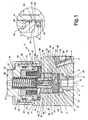
- Figure 1 is a partial cross-sectional view of a fuel injector provided with an adjustable-metering servo valve according to a first embodiment of the invention;
- Figure 2 is a detail of a variant of the servo valve of the embodiment of Figure 1;
- Figure 3 is the detail of the servo valve of Figure 2, in a second embodiment of the invention;
- Figure 4 is the detail of a variant of the servo valve of the embodiment of Figure 3;
- Figure 5 is the detail of the servo valve of Figure 2, in a third embodiment of the invention; and
- Figure 6 is the detail of a variant of the servo valve of the embodiment of Figure 5.
- With reference to Figure 1,
number 1 designates as a whole a fuel injector (partially illustrated), for an internal-combustion engine, in particular, a diesel engine. Theinjector 1 comprises a hollow body orcasing 2, which extends along alongitudinal axis 3, and has alateral inlet 4 designed to be connected to a pipe 4' for delivery of the fuel at a high pressure, for example at a pressure in the region of 1800 bar. Thecasing 2 terminates with a nozzle (not illustrated) communicating with theinlet 4 through apipe 5 and designed to inject the fuel into a corresponding cylinder of the engine. - The
casing 2 has anaxial cavity 6, housed in which is ametering servo valve 7 comprising avalve body 8. Thebody 8 has anaxial hole 9 in which acontrol rod 10 is able to slide in a fluid-tight way. Thebody 8 moreover has aflange 11 normally resting against ashoulder 12 of thecavity 6. Thecontrol rod 10 is designed to control a shutter needle (not illustrated) for opening and closing the fuel-injection nozzle, as will be seen in greater detail in what follows. - The
casing 2 is provided with anothercavity 13, which also shares theaxis 3, housed in which is anactuator device 14, comprising anelectromagnet 15. This is designed to control a notched-disk armature 16, which is fixed to asleeve 17. Theelectromagnet 15 is formed by amagnetic core 18, having apolar surface 19 perpendicular to theaxis 3. Theelectromagnet 15 is kept in position by asupport 20 in a way that will emerge more clearly from what follows. - The
magnetic core 18 is provided with a cavity 18' set in the area corresponding to asimilar cavity 21 of thesupport 20. The twocavities 18' and 21 also share thesame axis 3, and house ahelical compression spring 22, pre-loaded so as to exert a thrust on thearmature 16 in a direction opposite to the attraction exerted by theelectromagnet 15. In particular, thespring 22 has one end resting against an internal shoulder 21' of thesupport 20 and another end acting on thearmature 16 through awasher 24, which comprises a block 24' for guiding the end of thespring 22. - The
servo valve 7 comprises acontrol chamber 23, which, through apassage 25 of thebody 8, communicates permanently with theinlet 4 to receive the fuel under pressure. Thecontrol chamber 23 is delimited axially on one side by therod 10 and on the other by anend disk 30 in contact with theflange 11 of thebody 8. Thecontrol chamber 23 also has an outlet or discharge passage of the fuel, designated as a whole by 26. Thepassage 26 is symmetrical with respect to theaxis 3 and comprises adischarge hole 27 with calibrated cross section, made in thedisk 30 along theaxis 3. Thepassage 26 moreover comprises adistribution stretch 35 made in abody 28 for guiding thearmature 16, which is set between thedisk 30 and theactuator 14. - The
body 28 comprises abase 29 axially tightened by means of a threadedring nut 31, screwed on aninternal thread 32 of thecasing 2. In particular, thebase 29 of thebody 28 is set in thecavity 6 and is pack tightened in a position fixed with respect to thedisk 30 and theflange 11 and in a fluid-tight way so as to bear axially upon theshoulder 12. Furthermore, thebody 28 comprises a pin orstem 33, which extends in cantilever fashion from thebase 29 along theaxis 3 in a direction opposite to thechamber 23. Thepin 33 is delimited on the outside by a cylindricallateral surface 34, designed to guide thesleeve 17 of thearmature 16 axially. - The
stem 33 is made of a single piece with thebase 29, and has tworadial holes 36, diametrally opposite to one another and in communication with anaxial portion 37 of thedistribution stretch 35 of thepassage 26, so that they are fluid-tight in communication with the calibratedhole 27. Theholes 36 give out from thestem 33, in an axial position adjacent to thebase 29. Made along thelateral surface 34 of thestem 33, in the area corresponding to theholes 36, is anannular chamber 38. Thesleeve 17 also has an internalcylindrical surface 39, fitted to thelateral surface 34 of thestem 33 substantially in a fluid-tight way, with calibrated diametral play, for example less than 4 µm. Alternatively, the fluid-tight fit between thesleeve 17 and thestem 33 can be obtained by interposition of seal elements. - The
sleeve 17 is designed to slide axially along thesurface 34, between an advanced end-of-travel position and a retracted end-of-travel position. The advanced end-of-travel position, represented in Figure 1, is such as to close thepassage 26, and is defined by the bearing arrest of an ownconical end 42 upon aconical shoulder 43 of thebody 28. The retracted end-of-travel position is such as to open completely the radial holes 36 of thepassage 26, and is defined by the arrest of thearmature 16 upon thepolar surface 19 of thecore 18. - It is to be noted that, in the advanced end-of-travel position, the fuel exerts a zero resultant of axial thrust on the
sleeve 17, given that the pressure in thechamber 23 acts radially on thesurface 34, whereas, in the retracted end-of-travel position, the fuel flows from the radial holes 36 to a discharge or recirculation channel (not illustrated), through anannular passage 44 between thering nut 31 and thesleeve 17, the notches of thearmature 16, and the cavity 18' of thecore support 20. - The
annular chamber 38 is designed to be opened and closed by ashutter 45, defined by a bottom portion of thesleeve 17, adjacent to theend 42, so that theshutter 45 is actuated together with thearmature 16 when theelectromagnet 15 is energized. In particular, thearmature 16 displaces towards the core 18 so as to open theservo valve 7, causing discharge of the fuel and hence a drop in the pressure of the fuel in thecontrol chamber 23. In this way, an axial translation of therod 10 is brought about, which controls opening and closing of the injection nozzle. De-energization of theelectromagnet 15 causes thespring 22 to bring thearmature 16 back into the position of Figure 1 so that theshutter 45 recloses thepassage 26 and hence theservo valve 7. - The
core 18 of theelectromagnet 15 is fixed in thecompartment 13 of thecasing 2 by means of a threadedring nut 40, which engages anannular shoulder 41 of thesupport 20. Thissupport 20 comprises ahollow portion 50 in which thecore 18 is housed, and anannular contact surface 51, having a pre-set area defined by an external diameter D and an internal diameter d. The lateral surface of the hollow portion 20' of thesupport 20 is set in a fluid-tight way in thecavity 13 of thecasing 2. - The
core 18 of theelectromagnet 15 is provided with aflange 52 that forms anannular shoulder 47, acting on which is theannular contact surface 51 of thehollow portion 50. In order to determine the stroke of theshutter 45 in the direction of the core 18, set between thepolar surface 19 of thecore 18 and anannular shoulder 49 of thecompartment 13 of thecasing 2 is at least oneannular shim 48 sharing theaxis 3. - According to the invention, the
shim 48 is made of a material having a hardness different from that of the material of thecore 18 of theactuator 14 or of thecasing 2 so as to cause a pre-set plastic deformation according to the tightening torque of thering nut 40 such as to guarantee the desired position for thecore 18. According to the first embodiment of the invention illustrated in Figures 1 and 2, the shim is made of a material having an adequate stiffness greater than that of the material of thecore 18. Whereas the core 18 can be made of soft iron (for example, FeSi3 with a Brinell hardness HB ≤ 100), theshim 48 can be made of steel or cast iron (for example, thermally treated C40 steel with a Brinell hardness HB = 240). - Set moreover between the
flange 52 and theshoulder 49 is anannular projection 53 having acontact surface 54 defined by an internal diameter D' and an external diameter d', which is contained at least in part in thecontact surface 51 of the hollow portion 50', in such a way that theflange 52 will discharge, directly on theshim 48, the axial action of the tightening torque of thering nut 40. - According to the variant of Figure 1 of the first embodiment, the
projection 53 is made of a single piece with thecore 18. Theprojection 53 is preferably set in the area corresponding to the width of theflange 52 and hence to the width of theannular surface 51 of thehollow portion 50. Theprojection 53 can also be set in such a way that its external diameter D' is comprised between the two diameters D and d of theannular surface 50, whilst the internal diameter d' is smaller than or equal to the internal diameter d of theannular surface 50. Of course, theshim 48 will have dimensions such as to engage in any case the entire surface of theprojection 53. By way of example, the width D-d of theannular surface 50 can be comprised between 3 and 5 mm, whereas the width D'-d' can be in the region of between 0.25 and 0.75 of the width of theannular surface 50. Thering nut 40 is designed to be screwed with a tightening torque of, for example, between 15 and 25 N.m. This torque determines, within said limits, a corresponding axial tightening load, such as to guarantee a plastic variation of theprojection 53, or reduction in height, of between 10 and 15 µm. - According to the variant of Figure 2, the
projection 53 is made of a single piece with a correspondingshim 48 and is directed towards thecore 18. Theprojection 53 has dimensions equal to those of the variant of Figure 1 and is set substantially in the same relative position with respect to theannular surface 51. Since theshim 48 is also made of a material having a hardness greater than that of the core 18, the axial load, determined by the tightening torque, now plastically deforms thesurface 19 of thecore 18. - In the second embodiment of Figures 3 and 4, the
casing 2 is made of a relatively hard material, for example, C45 steel thermally treated so as to achieve a surface hardness HB = 240. Theshim 48 can be made of a material softer than that of thecasing 2, for example, C10 steel with a Brinell hardness HB ≤ 130 so that the axial load, determined by the tightening torque, plastically deforms theshim 48. - According to the variant of Figure 3 of the second embodiment, the
projection 53 is made of a single piece with theshim 48 and is directed towards theshoulder 49 of thecompartment 13 of thecasing 2. Theprojection 53 has the same dimensions as that of the variant of Figure 2 and is substantially set in the same position with respect to theannular surface 51. In this case, the plastic deformation is obtained on theprojection 53. - In the variant of Figure 4 of the second embodiment, the
projection 53 is made of a single piece with theshoulder 49, has the same dimensions as that of the variant of Figure 3 and is set substantially in the position with respect to theannular surface 51. In this variant the axial load, determined by the tightening torque, plastically deforms theshim 48. - According to the third embodiment of Figures 5 and 6, since the
core 18 is in general made of a material softer than that of thecasing 2, theshim 48 can be omitted. In particular, according to the variant of Figure 5, theprojection 53 is made of a single piece with theflange 53 of the core 18 as in Figure 1, and is designed to be deformed plastically by the axial thrust determined by the tightening torque of thering nut 40. Advantageously, in this case theshoulder 49 of thecompartment 13 is provided with an undercut 55 to enable the stroke of thearmature 16. - Instead, according to the variant of Figure 6 of the third embodiment, the
projection 53 is made of a single piece with thecasing 2 as in Figure 3, and is designed to deform thesurface 19 of theflange 47 plastically by the axial thrust determined by the tightening torque of thering nut 40. Advantageously, in this case, theshoulder 49 of thecompartment 13 can also be provided with an undercut 55 to enable the stroke of thearmature 16. In addition, or alternatively, theflange 52 can be provided with aribbing 56 such as to define adeformable surface 19 distinct from the polar surface 19' of thecore 18. - From a practical standpoint, since the plastic deformation of the projection 53 (Figures 1 and 3), or else of the
deformable surface 19 of the core 18 (Figures 2 and 4), is always relatively limited, it could be advisable to provide a magazine ofshims 48, of modular dimensions, i.e., divided in classes of thickness. Advantageously, in all of the embodiments described just oneshim 48 may at the most be used and may be coupled to one or more additional rigid shims, which can be calibrated and of modular dimensions and can be chosen so as to reduce to a minimum the plastic deformation of theprojection 53 or of thesurface 19 of the core 18 or of the surface of theshim 48. In particular, the additional modular shims are essential in the case of the variants of Figures 5 and 6. - Consequently, it is clear that, in all the cases described above, the adjustment of the stroke of the
armature 16 is obtained by providing in thecompartment 13 at least oneprojection 48, together with one or more stiff modular shims, in such a way that, with a pre-set tightening torque of thering nut 40, fine adjustment by successive approximations is obtained, for example by rotating each time thering nut 40 through a pre-set angle. - From what has been seen above, there emerge clearly the advantages of the injector with an adjustable-metering servo valve according to the invention as compared to the known art. In the first place, it is possible to obtain a continuous adjustment with maximum precision for the stroke of the
armature 16. Furthermore, the need for various classes of modular shims is reduced to the minimum or eliminated altogether. The need for a high precision of machining both of theshims 48 and of the additional stiff shims, which concur in determining the lift of the armature, is also reduced, as likewise the need for a high precision of machining of the casing, of the magnetic core and theentire servo valve 7. Also eliminated is the need for software compensation by the electronic control unit of any possible differences between the injectors. Finally, thanks to thebalanced shutter 45, on the one hand it is possible to use as arrest of thearmature 16 directly thepolar surface 19, and on the other hand the axial load to be generated on theprojection 48 to obtain the desired variations in dimensions is reduced. - It is understood that various modifications and improvements can be made to the injectors with adjustable-metering servo valve described above without departing from the scope of the claims. For example, the
projection 48 can have a cross section other than the rectangular one described and illustrated, in particular a trapezial cross section. Furthermore, theend disk 30 of thevalve body 8 can also be made of a single piece with the latter, and thearmature 16 can be provided with a thin layer of non-magnetic material functioning as gap. Finally, theactuator 14 can be of a different type, for example, of a piezoelectric type.
Claims (17)
- A fuel injector with adjustable-metering servo valve (7) for an internal-combustion engine, comprising a casing (2), housed in which are said servo valve (7) and an actuator (14) comprising a mobile member (16) for controlling a shutter (45) of said servo valve (7), and an element of arrest (19) for defining an opening stroke of said mobile member (16), said element of arrest (19) being fixed in said casing (2) by means of a threaded member (40) acting on a hollow body (20) provided with a first annular surface (51) of contact with said actuator (14), at least one shim (48) being set between said element of arrest (19) and a portion (49) of said casing (2), said threaded member (40) being screwed with a pre-set tightening torque on a thread (46) of said casing (2) so as to determine a corresponding tightening load on said shim (48); said fuel injector being characterized in that said shim (48) is formed with a material having a hardness different from that of the material of said element of arrest (19) or of said casing (2), an annular projection (53) having a second annular contact surface (54) being provided between said element of arrest (19) and said casing (2), said second contact surface (54) being contained at least in part in the area corresponding to said first contact surface (51) so as to adjust the stroke of said mobile member (16) by means of a pre-set plastic deformation of said shim (48) or element of arrest (19) as a function of said tightening torque.
- The injector according to Claim 1, in which said shutter (45) is controlled by an armature (16) of an electromagnet (15) having a core (18) provided with a flange (52), said threaded member being formed by a ring nut (40) acting on said flange (52), said injector being characterized in that said shim (48) is set between said flange (52) and a shoulder (49) of said casing (2).
- The injector according to Claim 2, characterized in that said shim (48) is formed with a material having a hardness greater than that of said flange (52), so that said plastic deformation is obtained on said flange (52).
- The injector according to Claim 3, characterized in that said annular projection (53) is made of a single piece with said flange (52), so that said deformation is obtained on said annular projection (53) .
- The injector according to Claim 3, characterized in that said annular projection (53) is made of a single piece with said shim (48), so that said deformation is obtained on said flange (52).
- The injector according to Claim 2, characterized in that said shim (48) is formed with a material having a hardness lower than that of said casing (2), so that said plastic deformation is obtained on said shim (48).
- The injector according to Claim 6, characterized in that said annular projection (53) is made of a single piece with said shim (48), so that said deformation is obtained on said annular projection (53).
- The injector according to Claim 6, characterized in that said annular projection (53) is made of a single piece with said shoulder (49), so that said deformation is obtained on said shim (48).
- The injector according to Claim 2, characterized in that said core (18) is formed with a material having a hardness lower than that of said casing (2), said annular projection (48) being set directly between said flange ((52) and said shoulder (49).
- The injector according to Claim 9, characterized in that said annular projection (53) is made of a single piece with said flange (52), so that said deformation is obtained on said annular projection (53).
- The injector according to Claim 10, characterized in that said annular projection (53) is made of a single piece with said shoulder (49), so that said deformation is obtained on said flange (52).
- The injector according to a of Claim 2 to 11, in which said first annular surface (51) has a corresponding external diameter (D) and a corresponding internal diameter (d), characterized in that said projection (53) has a rectangular or trapezial cross section, said second annular surface (54) having an external diameter (D') comprised between the external and internal diameters (D, d) of said first annular surface (51).
- The injector according to Claim 12, characterized in that the internal diameter (d') of said second annular surface (54) is also comprised between the external and internal diameters (D, d) of said first annular surface (51).
- The injector according to Claim 12 or Claim 13, characterized in that the internal diameter (d') of said second annular surface (54) is not greater than the internal diameter (d) of said first annular surface (51).
- The injector according to any one of Claims 2 to 14, characterized in that said shim (48) is chosen between a plurality of classes of calibrated and modular shims (48).
- The injector according to any one of Claims 2 to 15, comprising a control chamber (23) in communication with a discharge passage (26), characterized in that said shutter (45) is formed by a sleeve (17) fixed to said armature (16), said sleeve (17) being able to slide on a stem (33) having at least one radial hole (36) of said discharge passage (26).
- The injector according to Claim 16, characterized in that said stem (33) is carried by a guide body (28) having a conical shoulder (43) of arrest for a closing stroke of said armature (16), said sleeve (17) comprising one end (42) designed to come to stop against said conical shoulder (43).
Priority Applications (5)
| Application Number | Priority Date | Filing Date | Title |
|---|---|---|---|
| EP06425256A EP1845256B1 (en) | 2006-04-11 | 2006-04-11 | Fuel injector with adjustable metering servo-valve for an internal-combustion engine |
| AT06425256T ATE456742T1 (en) | 2006-04-11 | 2006-04-11 | FUEL INJECTOR FOR COMBUSTION ENGINES WITH ADJUSTABLE METERING SERVO VALVE |
| DE602006012012T DE602006012012D1 (en) | 2006-04-11 | 2006-04-11 | Fuel injector for internal combustion engines with adjustable metering valve |
| JP2007102133A JP4573851B2 (en) | 2006-04-11 | 2007-04-09 | Fuel injector with adjustable metering servo valve for internal combustion engines |
| US11/784,946 US7552909B2 (en) | 2006-04-11 | 2007-04-10 | Fuel injector with adjustable-metering servo valve for an internal-combustion engine |
Applications Claiming Priority (1)
| Application Number | Priority Date | Filing Date | Title |
|---|---|---|---|
| EP06425256A EP1845256B1 (en) | 2006-04-11 | 2006-04-11 | Fuel injector with adjustable metering servo-valve for an internal-combustion engine |
Publications (2)
| Publication Number | Publication Date |
|---|---|
| EP1845256A1 true EP1845256A1 (en) | 2007-10-17 |
| EP1845256B1 EP1845256B1 (en) | 2010-01-27 |
Family
ID=36968584
Family Applications (1)
| Application Number | Title | Priority Date | Filing Date |
|---|---|---|---|
| EP06425256A Active EP1845256B1 (en) | 2006-04-11 | 2006-04-11 | Fuel injector with adjustable metering servo-valve for an internal-combustion engine |
Country Status (5)
| Country | Link |
|---|---|
| US (1) | US7552909B2 (en) |
| EP (1) | EP1845256B1 (en) |
| JP (1) | JP4573851B2 (en) |
| AT (1) | ATE456742T1 (en) |
| DE (1) | DE602006012012D1 (en) |
Cited By (3)
| Publication number | Priority date | Publication date | Assignee | Title |
|---|---|---|---|---|
| EP2256335A1 (en) * | 2009-05-19 | 2010-12-01 | Robert Bosch GmbH | Method for adjusting valve lift |
| WO2011054869A1 (en) * | 2009-11-03 | 2011-05-12 | Continental Automotive Gmbh | Injection valve |
| CN111373139A (en) * | 2017-11-16 | 2020-07-03 | 日立汽车系统株式会社 | High-pressure fuel pump |
Families Citing this family (5)
| Publication number | Priority date | Publication date | Assignee | Title |
|---|---|---|---|---|
| DE102012205503A1 (en) * | 2012-04-04 | 2013-10-10 | Continental Teves Ag & Co. Ohg | Electromagnetic valve, in particular for slip-controlled motor vehicle brake systems |
| DE102012206890A1 (en) * | 2012-04-26 | 2013-10-31 | Robert Bosch Gmbh | Arrangement with a fuel distributor and a plurality of fuel injection valves |
| DE102013224719A1 (en) * | 2013-12-03 | 2015-06-03 | Robert Bosch Gmbh | Magnetic assembly for a solenoid valve |
| US9897033B2 (en) * | 2014-05-15 | 2018-02-20 | Cummins Inc. | High pressure, high speed regulating switch valve |
| US9677523B2 (en) * | 2014-05-30 | 2017-06-13 | Cummins Inc. | Fuel injector including an injection control valve having an improved stator core |
Citations (7)
| Publication number | Priority date | Publication date | Assignee | Title |
|---|---|---|---|---|
| US4365747A (en) * | 1979-09-08 | 1982-12-28 | Robert Bosch Gmbh | Electromagnetically actuatable fuel injection valve |
| EP0450532A1 (en) * | 1990-04-06 | 1991-10-09 | ELASIS SISTEMA RICERCA FIAT NEL MEZZOGIORNO Società Consortile per Azioni | An electromagnetically actuated fuel injection device for an internal combustion engine |
| WO1996041947A1 (en) * | 1995-06-08 | 1996-12-27 | Siemens Automotive Corporation | Method of adjusting a solenoid air gap |
| EP0905371A2 (en) * | 1997-09-24 | 1999-03-31 | MAGNETI MARELLI S.p.A. | Electromagnetic injector |
| EP0916843A1 (en) * | 1997-11-18 | 1999-05-19 | ELASIS SISTEMA RICERCA FIAT NEL MEZZOGIORNO Società Consortile per Azioni | Adjustable metering valve for an internal combustion engine fuel injector |
| EP1219828A2 (en) * | 2000-12-29 | 2002-07-03 | C.R.F. Società Consortile per Azioni | Internal combustion engine common-rail injection system with a fuel premetering device |
| GB2378985A (en) * | 2001-07-09 | 2003-02-26 | Bosch Gmbh Robert | Adjusting the magnet stroke in fuel injection solenoid valves |
Family Cites Families (7)
| Publication number | Priority date | Publication date | Assignee | Title |
|---|---|---|---|---|
| JPH08177679A (en) * | 1994-12-21 | 1996-07-12 | Nippondenso Co Ltd | Fuel injection valve |
| IT1293432B1 (en) * | 1997-07-11 | 1999-03-01 | Elasis Sistema Ricerca Fiat | FUEL INJECTOR FOR INTERNAL COMBUSTION ENGINES. |
| IT1293433B1 (en) | 1997-07-11 | 1999-03-01 | Elasis Sistema Ricerca Fiat | ADJUSTABLE DOSING VALVE FOR A FUEL INJECTOR FOR INTERNAL COMBUSTION ENGINES, AND RELEVANT ADJUSTMENT METHOD. |
| IT1295462B1 (en) * | 1997-10-02 | 1999-05-12 | Elasis Sistema Ricerca Fiat | FUEL INJECTOR WITH ELECTROMAGNETIC CONTROL FOR INTERNAL COMBUSTION ENGINES. |
| ITTO20001230A1 (en) * | 2000-12-29 | 2002-06-29 | Fiat Ricerche | FUEL INJECTOR FOR AN INTERNAL COMBUSTION ENGINE. |
| DE602005021310D1 (en) * | 2005-03-14 | 2010-07-01 | Fiat Ricerche | Adjustable metering valve of an injector and its adjustment method |
| EP1707797B1 (en) * | 2005-03-14 | 2007-08-22 | C.R.F. Società Consortile per Azioni | Adjustable metering servovalve for a fuel injector |
-
2006
- 2006-04-11 DE DE602006012012T patent/DE602006012012D1/en active Active
- 2006-04-11 AT AT06425256T patent/ATE456742T1/en not_active IP Right Cessation
- 2006-04-11 EP EP06425256A patent/EP1845256B1/en active Active
-
2007
- 2007-04-09 JP JP2007102133A patent/JP4573851B2/en active Active
- 2007-04-10 US US11/784,946 patent/US7552909B2/en active Active
Patent Citations (7)
| Publication number | Priority date | Publication date | Assignee | Title |
|---|---|---|---|---|
| US4365747A (en) * | 1979-09-08 | 1982-12-28 | Robert Bosch Gmbh | Electromagnetically actuatable fuel injection valve |
| EP0450532A1 (en) * | 1990-04-06 | 1991-10-09 | ELASIS SISTEMA RICERCA FIAT NEL MEZZOGIORNO Società Consortile per Azioni | An electromagnetically actuated fuel injection device for an internal combustion engine |
| WO1996041947A1 (en) * | 1995-06-08 | 1996-12-27 | Siemens Automotive Corporation | Method of adjusting a solenoid air gap |
| EP0905371A2 (en) * | 1997-09-24 | 1999-03-31 | MAGNETI MARELLI S.p.A. | Electromagnetic injector |
| EP0916843A1 (en) * | 1997-11-18 | 1999-05-19 | ELASIS SISTEMA RICERCA FIAT NEL MEZZOGIORNO Società Consortile per Azioni | Adjustable metering valve for an internal combustion engine fuel injector |
| EP1219828A2 (en) * | 2000-12-29 | 2002-07-03 | C.R.F. Società Consortile per Azioni | Internal combustion engine common-rail injection system with a fuel premetering device |
| GB2378985A (en) * | 2001-07-09 | 2003-02-26 | Bosch Gmbh Robert | Adjusting the magnet stroke in fuel injection solenoid valves |
Cited By (5)
| Publication number | Priority date | Publication date | Assignee | Title |
|---|---|---|---|---|
| EP2256335A1 (en) * | 2009-05-19 | 2010-12-01 | Robert Bosch GmbH | Method for adjusting valve lift |
| US9097228B2 (en) | 2009-05-19 | 2015-08-04 | Robert Bosch Gmbh | Method for adjusting the valve stroke |
| WO2011054869A1 (en) * | 2009-11-03 | 2011-05-12 | Continental Automotive Gmbh | Injection valve |
| US8998104B2 (en) | 2009-11-03 | 2015-04-07 | Continental Automotive Gmbh | Injection valve |
| CN111373139A (en) * | 2017-11-16 | 2020-07-03 | 日立汽车系统株式会社 | High-pressure fuel pump |
Also Published As
| Publication number | Publication date |
|---|---|
| EP1845256B1 (en) | 2010-01-27 |
| US20070251498A1 (en) | 2007-11-01 |
| US7552909B2 (en) | 2009-06-30 |
| JP2007278295A (en) | 2007-10-25 |
| JP4573851B2 (en) | 2010-11-04 |
| ATE456742T1 (en) | 2010-02-15 |
| DE602006012012D1 (en) | 2010-03-18 |
Similar Documents
| Publication | Publication Date | Title |
|---|---|---|
| EP1845256B1 (en) | Fuel injector with adjustable metering servo-valve for an internal-combustion engine | |
| EP1707797B1 (en) | Adjustable metering servovalve for a fuel injector | |
| JP4358831B2 (en) | Adjustable throttle servo valve for fuel injector and related adjustment method | |
| EP2373877B1 (en) | High operation repeatability and stability fuel injection system for an internal combustion engine | |
| US7513445B2 (en) | Metering solenoid valve for a fuel injector | |
| US5803369A (en) | Accumulator fuel injection device | |
| JP4188845B2 (en) | Adjustable pressure regulating valve for fuel injection system | |
| EP1731752A1 (en) | Fuel-control servo valve, and fuel injector provided with such servo valve | |
| US6745750B2 (en) | Fuel injection system for internal combustion engines | |
| US6405941B2 (en) | Fuel injection valve for internal combustion engines | |
| US7568634B2 (en) | Injection nozzle | |
| US20060151637A1 (en) | Injection valve | |
| RU2517518C2 (en) | Fuel injector with electromagnet armature composed of two parts | |
| US6105879A (en) | Fuel injection valve | |
| EP3146194B1 (en) | Injector for injecting fluid | |
| US6964266B2 (en) | 3/2 Directional-control valve | |
| CN112352096B (en) | Fuel injector | |
| JP2003507641A (en) | Injector | |
| EP1717435B1 (en) | Injection nozzle |
Legal Events
| Date | Code | Title | Description |
|---|---|---|---|
| PUAI | Public reference made under article 153(3) epc to a published international application that has entered the european phase |
Free format text: ORIGINAL CODE: 0009012 |
|
| 17P | Request for examination filed |
Effective date: 20070430 |
|
| AK | Designated contracting states |
Kind code of ref document: A1 Designated state(s): AT BE BG CH CY CZ DE DK EE ES FI FR GB GR HU IE IS IT LI LT LU LV MC NL PL PT RO SE SI SK TR |
|
| AX | Request for extension of the european patent |
Extension state: AL BA HR MK YU |
|
| AKX | Designation fees paid |
Designated state(s): AT BE BG CH CY CZ DE DK EE ES FI FR GB GR HU IE IS IT LI LT LU LV MC NL PL PT RO SE SI SK TR |
|
| GRAP | Despatch of communication of intention to grant a patent |
Free format text: ORIGINAL CODE: EPIDOSNIGR1 |
|
| GRAS | Grant fee paid |
Free format text: ORIGINAL CODE: EPIDOSNIGR3 |
|
| GRAA | (expected) grant |
Free format text: ORIGINAL CODE: 0009210 |
|
| AK | Designated contracting states |
Kind code of ref document: B1 Designated state(s): AT BE BG CH CY CZ DE DK EE ES FI FR GB GR HU IE IS IT LI LT LU LV MC NL PL PT RO SE SI SK TR |
|
| REG | Reference to a national code |
Ref country code: GB Ref legal event code: FG4D |
|
| REG | Reference to a national code |
Ref country code: CH Ref legal event code: EP |
|
| REG | Reference to a national code |
Ref country code: IE Ref legal event code: FG4D |
|
| REF | Corresponds to: |
Ref document number: 602006012012 Country of ref document: DE Date of ref document: 20100318 Kind code of ref document: P |
|
| REG | Reference to a national code |
Ref country code: NL Ref legal event code: VDEP Effective date: 20100127 |
|
| LTIE | Lt: invalidation of european patent or patent extension |
Effective date: 20100127 |
|
| PG25 | Lapsed in a contracting state [announced via postgrant information from national office to epo] |
Ref country code: AT Free format text: LAPSE BECAUSE OF FAILURE TO SUBMIT A TRANSLATION OF THE DESCRIPTION OR TO PAY THE FEE WITHIN THE PRESCRIBED TIME-LIMIT Effective date: 20100127 |
|
| PG25 | Lapsed in a contracting state [announced via postgrant information from national office to epo] |
Ref country code: ES Free format text: LAPSE BECAUSE OF FAILURE TO SUBMIT A TRANSLATION OF THE DESCRIPTION OR TO PAY THE FEE WITHIN THE PRESCRIBED TIME-LIMIT Effective date: 20100508 Ref country code: NL Free format text: LAPSE BECAUSE OF FAILURE TO SUBMIT A TRANSLATION OF THE DESCRIPTION OR TO PAY THE FEE WITHIN THE PRESCRIBED TIME-LIMIT Effective date: 20100127 Ref country code: IS Free format text: LAPSE BECAUSE OF FAILURE TO SUBMIT A TRANSLATION OF THE DESCRIPTION OR TO PAY THE FEE WITHIN THE PRESCRIBED TIME-LIMIT Effective date: 20100527 Ref country code: PT Free format text: LAPSE BECAUSE OF FAILURE TO SUBMIT A TRANSLATION OF THE DESCRIPTION OR TO PAY THE FEE WITHIN THE PRESCRIBED TIME-LIMIT Effective date: 20100527 Ref country code: LT Free format text: LAPSE BECAUSE OF FAILURE TO SUBMIT A TRANSLATION OF THE DESCRIPTION OR TO PAY THE FEE WITHIN THE PRESCRIBED TIME-LIMIT Effective date: 20100127 |
|
| PG25 | Lapsed in a contracting state [announced via postgrant information from national office to epo] |
Ref country code: LV Free format text: LAPSE BECAUSE OF FAILURE TO SUBMIT A TRANSLATION OF THE DESCRIPTION OR TO PAY THE FEE WITHIN THE PRESCRIBED TIME-LIMIT Effective date: 20100127 Ref country code: FI Free format text: LAPSE BECAUSE OF FAILURE TO SUBMIT A TRANSLATION OF THE DESCRIPTION OR TO PAY THE FEE WITHIN THE PRESCRIBED TIME-LIMIT Effective date: 20100127 Ref country code: PL Free format text: LAPSE BECAUSE OF FAILURE TO SUBMIT A TRANSLATION OF THE DESCRIPTION OR TO PAY THE FEE WITHIN THE PRESCRIBED TIME-LIMIT Effective date: 20100127 Ref country code: SI Free format text: LAPSE BECAUSE OF FAILURE TO SUBMIT A TRANSLATION OF THE DESCRIPTION OR TO PAY THE FEE WITHIN THE PRESCRIBED TIME-LIMIT Effective date: 20100127 |
|
| PG25 | Lapsed in a contracting state [announced via postgrant information from national office to epo] |
Ref country code: SE Free format text: LAPSE BECAUSE OF FAILURE TO SUBMIT A TRANSLATION OF THE DESCRIPTION OR TO PAY THE FEE WITHIN THE PRESCRIBED TIME-LIMIT Effective date: 20100127 Ref country code: RO Free format text: LAPSE BECAUSE OF FAILURE TO SUBMIT A TRANSLATION OF THE DESCRIPTION OR TO PAY THE FEE WITHIN THE PRESCRIBED TIME-LIMIT Effective date: 20100127 Ref country code: CY Free format text: LAPSE BECAUSE OF FAILURE TO SUBMIT A TRANSLATION OF THE DESCRIPTION OR TO PAY THE FEE WITHIN THE PRESCRIBED TIME-LIMIT Effective date: 20100127 Ref country code: GR Free format text: LAPSE BECAUSE OF FAILURE TO SUBMIT A TRANSLATION OF THE DESCRIPTION OR TO PAY THE FEE WITHIN THE PRESCRIBED TIME-LIMIT Effective date: 20100428 Ref country code: BE Free format text: LAPSE BECAUSE OF FAILURE TO SUBMIT A TRANSLATION OF THE DESCRIPTION OR TO PAY THE FEE WITHIN THE PRESCRIBED TIME-LIMIT Effective date: 20100127 Ref country code: EE Free format text: LAPSE BECAUSE OF FAILURE TO SUBMIT A TRANSLATION OF THE DESCRIPTION OR TO PAY THE FEE WITHIN THE PRESCRIBED TIME-LIMIT Effective date: 20100127 |
|
| PG25 | Lapsed in a contracting state [announced via postgrant information from national office to epo] |
Ref country code: MC Free format text: LAPSE BECAUSE OF NON-PAYMENT OF DUE FEES Effective date: 20100430 Ref country code: BG Free format text: LAPSE BECAUSE OF FAILURE TO SUBMIT A TRANSLATION OF THE DESCRIPTION OR TO PAY THE FEE WITHIN THE PRESCRIBED TIME-LIMIT Effective date: 20100427 Ref country code: CZ Free format text: LAPSE BECAUSE OF FAILURE TO SUBMIT A TRANSLATION OF THE DESCRIPTION OR TO PAY THE FEE WITHIN THE PRESCRIBED TIME-LIMIT Effective date: 20100127 Ref country code: SK Free format text: LAPSE BECAUSE OF FAILURE TO SUBMIT A TRANSLATION OF THE DESCRIPTION OR TO PAY THE FEE WITHIN THE PRESCRIBED TIME-LIMIT Effective date: 20100127 |
|
| REG | Reference to a national code |
Ref country code: CH Ref legal event code: PL |
|
| PLBE | No opposition filed within time limit |
Free format text: ORIGINAL CODE: 0009261 |
|
| STAA | Information on the status of an ep patent application or granted ep patent |
Free format text: STATUS: NO OPPOSITION FILED WITHIN TIME LIMIT |
|
| GBPC | Gb: european patent ceased through non-payment of renewal fee |
Effective date: 20100427 |
|
| 26N | No opposition filed |
Effective date: 20101028 |
|
| PG25 | Lapsed in a contracting state [announced via postgrant information from national office to epo] |
Ref country code: IE Free format text: LAPSE BECAUSE OF NON-PAYMENT OF DUE FEES Effective date: 20100411 Ref country code: DK Free format text: LAPSE BECAUSE OF FAILURE TO SUBMIT A TRANSLATION OF THE DESCRIPTION OR TO PAY THE FEE WITHIN THE PRESCRIBED TIME-LIMIT Effective date: 20100127 |
|
| PG25 | Lapsed in a contracting state [announced via postgrant information from national office to epo] |
Ref country code: CH Free format text: LAPSE BECAUSE OF NON-PAYMENT OF DUE FEES Effective date: 20100430 Ref country code: LI Free format text: LAPSE BECAUSE OF NON-PAYMENT OF DUE FEES Effective date: 20100430 |
|
| PG25 | Lapsed in a contracting state [announced via postgrant information from national office to epo] |
Ref country code: GB Free format text: LAPSE BECAUSE OF NON-PAYMENT OF DUE FEES Effective date: 20100427 |
|
| PG25 | Lapsed in a contracting state [announced via postgrant information from national office to epo] |
Ref country code: LU Free format text: LAPSE BECAUSE OF NON-PAYMENT OF DUE FEES Effective date: 20100411 Ref country code: HU Free format text: LAPSE BECAUSE OF FAILURE TO SUBMIT A TRANSLATION OF THE DESCRIPTION OR TO PAY THE FEE WITHIN THE PRESCRIBED TIME-LIMIT Effective date: 20100728 |
|
| PG25 | Lapsed in a contracting state [announced via postgrant information from national office to epo] |
Ref country code: TR Free format text: LAPSE BECAUSE OF FAILURE TO SUBMIT A TRANSLATION OF THE DESCRIPTION OR TO PAY THE FEE WITHIN THE PRESCRIBED TIME-LIMIT Effective date: 20100127 |
|
| REG | Reference to a national code |
Ref country code: FR Ref legal event code: PLFP Year of fee payment: 11 |
|
| REG | Reference to a national code |
Ref country code: FR Ref legal event code: PLFP Year of fee payment: 12 |
|
| REG | Reference to a national code |
Ref country code: FR Ref legal event code: PLFP Year of fee payment: 13 |
|
| PGFP | Annual fee paid to national office [announced via postgrant information from national office to epo] |
Ref country code: IT Payment date: 20240320 Year of fee payment: 19 Ref country code: FR Payment date: 20240320 Year of fee payment: 19 |
|
| PGFP | Annual fee paid to national office [announced via postgrant information from national office to epo] |
Ref country code: DE Payment date: 20240320 Year of fee payment: 19 |