EP1845126B1 - Dual cure resin composite system and method of manufacturing the same - Google Patents
Dual cure resin composite system and method of manufacturing the same Download PDFInfo
- Publication number
- EP1845126B1 EP1845126B1 EP20070105592 EP07105592A EP1845126B1 EP 1845126 B1 EP1845126 B1 EP 1845126B1 EP 20070105592 EP20070105592 EP 20070105592 EP 07105592 A EP07105592 A EP 07105592A EP 1845126 B1 EP1845126 B1 EP 1845126B1
- Authority
- EP
- European Patent Office
- Prior art keywords
- layer
- curing
- functional group
- source
- resin
- Prior art date
- Legal status (The legal status is an assumption and is not a legal conclusion. Google has not performed a legal analysis and makes no representation as to the accuracy of the status listed.)
- Not-in-force
Links
- 230000009977 dual effect Effects 0.000 title description 33
- 238000004519 manufacturing process Methods 0.000 title description 18
- 239000000805 composite resin Substances 0.000 title 1
- 125000000524 functional group Chemical group 0.000 claims description 71
- 229920005989 resin Polymers 0.000 claims description 41
- 239000011347 resin Substances 0.000 claims description 41
- 238000000034 method Methods 0.000 claims description 30
- 230000005855 radiation Effects 0.000 claims description 16
- 230000004044 response Effects 0.000 claims description 16
- 230000003213 activating effect Effects 0.000 claims description 13
- 239000010410 layer Substances 0.000 description 142
- 238000001723 curing Methods 0.000 description 131
- 239000002131 composite material Substances 0.000 description 58
- 230000007246 mechanism Effects 0.000 description 29
- 239000004593 Epoxy Substances 0.000 description 8
- NIXOWILDQLNWCW-UHFFFAOYSA-M Acrylate Chemical compound [O-]C(=O)C=C NIXOWILDQLNWCW-UHFFFAOYSA-M 0.000 description 7
- 239000000463 material Substances 0.000 description 6
- OKTJSMMVPCPJKN-UHFFFAOYSA-N Carbon Chemical compound [C] OKTJSMMVPCPJKN-UHFFFAOYSA-N 0.000 description 4
- 239000000853 adhesive Substances 0.000 description 4
- 230000001070 adhesive effect Effects 0.000 description 4
- 229910052799 carbon Inorganic materials 0.000 description 4
- 238000010894 electron beam technology Methods 0.000 description 4
- 239000011152 fibreglass Substances 0.000 description 4
- 230000008569 process Effects 0.000 description 4
- CNPURSDMOWDNOQ-UHFFFAOYSA-N 4-methoxy-7h-pyrrolo[2,3-d]pyrimidin-2-amine Chemical compound COC1=NC(N)=NC2=C1C=CN2 CNPURSDMOWDNOQ-UHFFFAOYSA-N 0.000 description 3
- 150000001412 amines Chemical class 0.000 description 3
- LFQSCWFLJHTTHZ-UHFFFAOYSA-N Ethanol Chemical compound CCO LFQSCWFLJHTTHZ-UHFFFAOYSA-N 0.000 description 2
- 230000004913 activation Effects 0.000 description 2
- 238000004026 adhesive bonding Methods 0.000 description 2
- 239000012952 cationic photoinitiator Substances 0.000 description 2
- 239000011248 coating agent Substances 0.000 description 2
- 238000000576 coating method Methods 0.000 description 2
- 238000005056 compaction Methods 0.000 description 2
- 150000001875 compounds Chemical class 0.000 description 2
- 239000000835 fiber Substances 0.000 description 2
- 239000012948 isocyanate Substances 0.000 description 2
- 150000002513 isocyanates Chemical class 0.000 description 2
- 238000005304 joining Methods 0.000 description 2
- -1 polyethylene Polymers 0.000 description 2
- 229920001567 vinyl ester resin Polymers 0.000 description 2
- 125000000391 vinyl group Chemical group [H]C([*])=C([H])[H] 0.000 description 2
- OXBLVCZKDOZZOJ-UHFFFAOYSA-N 2,3-Dihydrothiophene Chemical group C1CC=CS1 OXBLVCZKDOZZOJ-UHFFFAOYSA-N 0.000 description 1
- 229920002748 Basalt fiber Polymers 0.000 description 1
- JOYRKODLDBILNP-UHFFFAOYSA-N Ethyl urethane Chemical compound CCOC(N)=O JOYRKODLDBILNP-UHFFFAOYSA-N 0.000 description 1
- 229920000877 Melamine resin Polymers 0.000 description 1
- CERQOIWHTDAKMF-UHFFFAOYSA-M Methacrylate Chemical compound CC(=C)C([O-])=O CERQOIWHTDAKMF-UHFFFAOYSA-M 0.000 description 1
- 239000004698 Polyethylene Substances 0.000 description 1
- 239000004642 Polyimide Substances 0.000 description 1
- 150000001252 acrylic acid derivatives Chemical class 0.000 description 1
- 150000001299 aldehydes Chemical class 0.000 description 1
- 239000011230 binding agent Substances 0.000 description 1
- 230000015556 catabolic process Effects 0.000 description 1
- 239000011951 cationic catalyst Substances 0.000 description 1
- 230000008859 change Effects 0.000 description 1
- 238000006243 chemical reaction Methods 0.000 description 1
- 238000009734 composite fabrication Methods 0.000 description 1
- 238000006731 degradation reaction Methods 0.000 description 1
- 238000010586 diagram Methods 0.000 description 1
- 125000003700 epoxy group Chemical group 0.000 description 1
- 125000003055 glycidyl group Chemical group C(C1CO1)* 0.000 description 1
- 125000002887 hydroxy group Chemical group [H]O* 0.000 description 1
- 230000010354 integration Effects 0.000 description 1
- 239000011229 interlayer Substances 0.000 description 1
- 150000007974 melamines Chemical class 0.000 description 1
- 150000002734 metacrylic acid derivatives Chemical class 0.000 description 1
- 239000000203 mixture Substances 0.000 description 1
- 150000002894 organic compounds Chemical class 0.000 description 1
- 150000002978 peroxides Chemical class 0.000 description 1
- 238000000016 photochemical curing Methods 0.000 description 1
- 229920000647 polyepoxide Polymers 0.000 description 1
- 229920000573 polyethylene Polymers 0.000 description 1
- 229920001721 polyimide Polymers 0.000 description 1
- 229920000642 polymer Polymers 0.000 description 1
- 229920005594 polymer fiber Polymers 0.000 description 1
- 235000013824 polyphenols Nutrition 0.000 description 1
- 238000007665 sagging Methods 0.000 description 1
- 229920006305 unsaturated polyester Polymers 0.000 description 1
- 150000003673 urethanes Chemical class 0.000 description 1
- 229920002554 vinyl polymer Polymers 0.000 description 1
Images


Classifications
-
- C—CHEMISTRY; METALLURGY
- C08—ORGANIC MACROMOLECULAR COMPOUNDS; THEIR PREPARATION OR CHEMICAL WORKING-UP; COMPOSITIONS BASED THEREON
- C08J—WORKING-UP; GENERAL PROCESSES OF COMPOUNDING; AFTER-TREATMENT NOT COVERED BY SUBCLASSES C08B, C08C, C08F, C08G or C08H
- C08J5/00—Manufacture of articles or shaped materials containing macromolecular substances
- C08J5/12—Bonding of a preformed macromolecular material to the same or other solid material such as metal, glass, leather, e.g. using adhesives
-
- Y—GENERAL TAGGING OF NEW TECHNOLOGICAL DEVELOPMENTS; GENERAL TAGGING OF CROSS-SECTIONAL TECHNOLOGIES SPANNING OVER SEVERAL SECTIONS OF THE IPC; TECHNICAL SUBJECTS COVERED BY FORMER USPC CROSS-REFERENCE ART COLLECTIONS [XRACs] AND DIGESTS
- Y10—TECHNICAL SUBJECTS COVERED BY FORMER USPC
- Y10T—TECHNICAL SUBJECTS COVERED BY FORMER US CLASSIFICATION
- Y10T428/00—Stock material or miscellaneous articles
- Y10T428/24—Structurally defined web or sheet [e.g., overall dimension, etc.]
- Y10T428/24058—Structurally defined web or sheet [e.g., overall dimension, etc.] including grain, strips, or filamentary elements in respective layers or components in angular relation
-
- Y—GENERAL TAGGING OF NEW TECHNOLOGICAL DEVELOPMENTS; GENERAL TAGGING OF CROSS-SECTIONAL TECHNOLOGIES SPANNING OVER SEVERAL SECTIONS OF THE IPC; TECHNICAL SUBJECTS COVERED BY FORMER USPC CROSS-REFERENCE ART COLLECTIONS [XRACs] AND DIGESTS
- Y10—TECHNICAL SUBJECTS COVERED BY FORMER USPC
- Y10T—TECHNICAL SUBJECTS COVERED BY FORMER US CLASSIFICATION
- Y10T428/00—Stock material or miscellaneous articles
- Y10T428/249921—Web or sheet containing structurally defined element or component
-
- Y—GENERAL TAGGING OF NEW TECHNOLOGICAL DEVELOPMENTS; GENERAL TAGGING OF CROSS-SECTIONAL TECHNOLOGIES SPANNING OVER SEVERAL SECTIONS OF THE IPC; TECHNICAL SUBJECTS COVERED BY FORMER USPC CROSS-REFERENCE ART COLLECTIONS [XRACs] AND DIGESTS
- Y10—TECHNICAL SUBJECTS COVERED BY FORMER USPC
- Y10T—TECHNICAL SUBJECTS COVERED BY FORMER US CLASSIFICATION
- Y10T428/00—Stock material or miscellaneous articles
- Y10T428/31504—Composite [nonstructural laminate]
- Y10T428/31536—Including interfacial reaction product of adjacent layers
Definitions
- the invention relates generally to fabrication techniques and, more particularly, composite fabrication techniques and associated polymer composite-based products.
- Structural composite products such as wind turbine blades and aircraft structures, are composed of multiple layers.
- the conventional approach for curing these multiple layers involves curing all of the layers together at the same time in an autoclave or oven. In other words, the process involves applying the layers one over the other, and then subsequently curing all of the layers.
- the adhesion between layers is generally good but other disadvantages sometimes make this approach not practical. For instance, in manufacturing the root section of a wind turbine blades, sagging and dimensional distortion and fiber wrinkling during compaction may occur during curing cycle. Also, excessive reaction exotherm from thick parts may cause problems.
- Another approach for curing these multiple layers involves sequentially applying and completely curing layers one after another using a single curing mechanism.
- a first composite layer is cured completely before laying down a second composite layer.
- the second composite layer is then cured completely before laying down a third composite layer.
- the process adds additional composite layers in the same sequential manner using the single curing mechanism.
- this fabrication technique creates relatively weak secondary adhesive bonds between the composite layers. These secondary adhesive bonds result in undesirably low interlaminar strength.
- WO 2004/035651 there is described a method of applying a coating to a sheet or bulk moulded compound. Applied films are partially cured with UV radiation, and the part-cured films are coated with a coating material. Both films are then jointly cured thermally.
- a concrete substate is coated with first and second polymerizable resin binder solutions, the solutions are exposed to UV radiation to cure portions of the resin solutions, and the uncured portions of the resin solutions are allowed to cure thermally over time.
- a dual cure composite structure used herein is defined as a composite structure having multiple layers, wherein the composite structure is manufactured using a "dual cure” mechanism to bond the multiple layers.
- “Dual cure” mechanism is a mechanism in which initially, a first layer is partially cured by a first curing feature followed by a second layer being disposed on top of the first layer. In a next step, the second layer is partially cured and the first layer is at least further or fully cured simultaneously by a second curing feature.
- the "dual cure” mechanism may be supplemented with one or more additional curing features, making the mechanism a generally "multi cure” mechanism.
- the foregoing dual cure scenario may be supplemented by further applying a third layer on top of the second layer, and then partially curing the third layer and further or entirely curing the second layer simultaneously by a third curing feature.
- the first layer also may be further or entirely cured by the third curing feature simultaneous with the curing of the second and third layers.
- a fourth, fifth, sixth, or additional layers may be successively applied over the composite structure, and successively cured in stages of partial, and eventually complete curing via two or more curing features (e.g., the first, second, or more curing features).
- the curing features generally alternate (e.g., feature 1, 2, 1,2, etc.) as each successive layer is applied and simultaneously partially cured along with a previous layer.
- the disclosed “dual cure” or “multi cure” mechanism may be described as “overlapping stages of curing” or “staged curing” or “step curing” of adjacent layers to create covalent bonds across interface of the layers and hence improve the interlayer adhesion.
- Rapid curing systems are desirable for large composite structures to obtain the desired manufacturing cycle time, reduce significant plant and equipment investment, and further decrease base cost of a part.
- This requires integration of appropriate resin chemistry with a corresponding curing source.
- Curing source is a source used in curing layers of a composite structure.
- Non-limiting examples of a curing source are ultraviolet frequency radiation, or microwave frequency radiation, or radio frequency, or visible frequency radiation, or ultrasonic, or laser, or electron beam or a combination thereof.
- FIG. 1 is a cross-sectional view of a dual cure composite structure 10 including a first layer 12, a second layer 14 and a third layer 16 of a resin or another material in accordance with embodiments of the present invention.
- resin includes a resin or a resin blend.
- the composite structure 10 may include two or more layers of a resin. In alternative embodiments, the composite structure 10 may include two or more layers of another type of material.
- the first layer 12 includes a first functional group 18 and a second functional group 20.
- the "functional group” is defined as an atom or a group of atoms in an organic compound that provides the compound with some of its characteristics which make it respond to a specific curing mechanism.
- Some non-limiting examples of functional groups include aldehydes, amines, hydroxyl, acrylate, methacrylate, vinyl, cyclo-epoxide, glycidyl etherepoxide with amine curatives, urethane, thiol-ene reactive group or a combination thereof.
- Some non-limiting examples of resins comprising these functional groups are unsaturated polyesters, vinyl esters, melamines, urea-formaledehydes, phenolics, methacrylates, acrylates, epoxies, urethanes, etc.
- a second layer 14 of the resin including the first functional group 18 and the second functional group 20 is disposed on the first layer 12.
- a third layer 16 of the resin including the first 18 and the second 20 functional groups is disposed on the second layer 14 of the resin.
- the first 12 and the second 14 layers are bonded by a covalent bond formed at an interface 22 of the two layers.
- the second 14 and the third 16 layers are bonded by a covalent bond at an interface 24 of the two layers.
- the composite structure 10 includes carbon, fiberglass, basalt fiber, and polymer fiber (such as polyethylene and polyimide) composites.
- Ex. 1 in Table 1 illustrates applying a curing source 1 (UV) source to initiate photo curing of the first functional group (acrylate) and applying curing source 2 (infrared) to thermally cure the second functional groups (epoxy with amine) according to the embodiment described in Fig. 1 .
- Ex. 2-Ex. 7 follow similar lines.
- FIG. 2 illustrates a method 30 of curing a dual composite structure 10 in accordance with the present invention.
- the method 30 includes activating a first functional group of a resin in a first layer in response to a first curing source at step 32.
- the method 30 further includes activating a second functional group of the first layer and the second functional group of a second layer disposed on top of the first layer in response to a second curing source at step 34.
- the first layer may be fully cured.
- the layers may include additional functional groups, such that the full curing of the layers may occur over three or more stages of curing with three or more curing sources.
- the illustrated embodiment includes two curing sources, such that each successive layer is generally completely cured in two stages.
- the method 30 further includes activating a first functional group of a third layer and the first functional group of the second layer in response to the first curing source at step 38. This leads to a partially cured third layer 16 (as referenced to in FIG. 1 ) and a fully cured second layer 14. These result in creating a second covalent bond across an interface of the second layer and the third layer at step 40.
- the method 30 further includes activating the second functional group of the third layer in response to the second curing source at step 42. This leads to a fully cured third layer 16. Simultaneous curing of two layers results in a stronger adhesive bonding than that formed via a single curing mechanism. This results in stronger interlaminar shear strengths and eliminates interlaminar property degradation.
- FIG. 3 illustrates an exemplary method 50 of manufacturing a dual cure composite structure 10 as referenced to in FIG. 1 comprising a first 12, a second 14 and a third 16 layer of resin in accordance with certain embodiments of the present invention.
- the first 12, the second 14 and the third 16 layers further include a first 18 and a second 20 functional group as referenced in FIG. 1 .
- the method 50 includes providing a first layer comprising a resin having a first functional group and a second functional group as step 52.
- the method 50 further includes applying a first curing source to partially cure the first layer at step 54.
- the term 'partial curing' refers to curing less than about 100% of a layer of a composite structure.
- partial curing may be about 10, 20, 30, 40, 50, 60, 70, 80, or 90 percent, or some percentage between these values. In an exemplary embodiment, the partial curing may be between about 30-70 percent, or between 40-60 percent, or about 50 percent. However, the degree of partial curing may vary depending on the particular materials, curing source, layer thickness, and so forth.
- the method 50 includes providing a second layer comprising the resin having the first and the second functional group onto the first layer as step 56. Following addition of the second layer, the method 50 includes applying a second curing source to fully cure the first layer and partially cure the second layer simultaneously as step 58.
- the third layer 16 may further be introduced by providing a third layer comprising the resin having the first and the second functional group onto the second layer as step 60. Simultaneous curing of the second 14 and the third 16 layers occur by applying the first curing source to fully cure the second layer and partially cure the third layer simultaneously as step 62. Full curing of the third layer 16 occurs by applying the second curing source to fully cure the third layer as step 64.
- FIG. 4 illustrates a method 66 of manufacturing and curing a dual cure composite structure 10 as referenced to in FIG. 1 including a first 12 and a second 14 layer.
- the method 66 includes partially curing a first composite layer with a first curing feature as step 68. Following the partial curing, a second composite layer 14 is introduced by disposing a second composite layer along the first composite layer as step 70.
- the method 66 further includes simultaneously curing the first and second composite layers with a second curing feature to further cure the first composite layer and to partially cure the second composite layer, wherein the first and second curing features are different from one another as step 72.
- the first and second curing features include different curing mechanisms, or the same curing mechanism having different output characteristics, or a combination of both. For example, several curing mechanisms and characteristics are described in further detail below.
- FIG. 5 illustrates a manufacturing system 76 used in a dual curing process of a dual cure composite structure 10 as referenced in FIG. 1 .
- the manufacturing system 76 comprises one or more curing sources 78 configured to simultaneously cure a first layer 80 and a second layer 82 of the dual cure composite structure 10.
- the manufacturing system 76 further includes a machine 84 configured to dispose the second layer 82 on top of the first layer 80.
- the machine 84 includes a machine that can be operated manually, or an automated machine, or a combination thereof.
- the machine 84 may include a flat press, a roll press, hydraulics, springs, pneumatics, gear mechanisms, or other compressive mechanisms to force the layers toward one another.
- a non-limiting example of an automated machine includes an automated fiber and tape placement head and compaction roller.
- the one or more curing sources 78 include an ultraviolet frequency radiation source, or a microwave frequency radiation source, or a radio frequency radiation source, or a visible frequency radiation source, or an ultrasonic radiation source, or an infrared, or a laser, or an electron beam or a combination thereof.
- the one or more curing source 78 may include different curing types or different characteristics of the same curing type.
- the one or more curing sources may include a single or two curing sources of the same type but emitting radiation (e.g., ultra-violet radiation) at different wavelengths, or frequencies.
- the one or more curing sources may include two different types such as one curing source with ultra-violet radiation and a different curing source with microwave radiation, or one curing source with electron beam and one curing source with infrared radiation, or one curing source with microwave and one curing source with electron beam, or one curing source with UV-A and one curing source with UV-B, or once curing source with one microwave frequency C and one curing source with another microwave frequency.
- Joining and assembling of piece-parts and subcomponents into monolithic structures is particularly advantageous and useful for modular design.
- adhesive bonds generally provide for lower weight designs and a desirable strength.
- the disclosed dual curing mechanism provides a desirable strength and potential for adhesive bonds in composite structures comprising resins as described in previous paragraphs.
- Composite structures including resins may be used as materials in mechanical components for desirable adhesive bonding during joining and assembling of mechanical components.
- FIG. 6 is a diagrammatical illustration of an exemplary embodiment of a dual composite structure 10 as referenced to in FIG. 1 , illustrating a wind turbine system 90 in accordance with embodiments of the present invention.
- Some of the characteristics that make composites, such as carbon and fiberglass composites, suitable for wind turbine blades are desirable mechanical properties, tailorability of material properties, and versatility of fabrication methods.
- the carbon and fiberglass composites provide desirable toughness and shorter process cycle time than that known in existing manufacturing processes.
- the wind turbine system 90 includes a plurality of blades 92 (e.g., three blades).
- the blades 92 enable the system 90 to capture energy from the wind. Specifically, the wind forces the blades 92 to rotate about an axis, thereby driving an electrical generator disposed within the system 90.
- the blades 92 of the wind turbine system 90 have a typical length of about 70 meters to maximize capture of energy and reduce cost of energy. Components of the blade 92 may comprise the dual cure composite structure 10 as discussed below.
- the blades 92 are coupled to a tower 94.
- the height of the tower which determines height of the wind turbine system 90, plays a significant part in design of the wind turbine system 90. Due to change in velocity of wind with altitude, also known as wind shear, an optimum height is desirable for optimum performance of the wind turbine system 90.
- height of the tower 94 is about two to three times length of the blades 92 for an optimal performance.
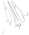
- FIG. 7 illustrates a modular design of a blade 92 as referenced in FIG. 6 of a wind turbine system 90 in accordance with certain embodiments of the present invention.
- the illustrated blade 92 includes a top skin 96 and a shear web 98 disposed between a pair of spar caps 100 that are coupled to a barrel 102.
- the shear web 98 provides desirable strength to the blade 92 and also provides desirable support to the pair of spar caps 100.
- the blade 92 further includes a bottom skin 104 disposed below the shear web 98.
- the pair of spar caps 100 is made of a dual cure composite 10, such as a carbon and a fiberglass composite.
- the blade 92 is a significant component of the wind turbine blade system 90 as referenced to in FIG.6 , using a dual cure composite structure 10 as referenced to in FIG. 1 and described in the aforementioned embodiments, provides desirable mechanical strength to the turbine blade system 90. Further, the top skin 96 and the bottom skin 104 may comprise the dual cure composite structure 10.
Landscapes
- Chemical & Material Sciences (AREA)
- Medicinal Chemistry (AREA)
- Manufacturing & Machinery (AREA)
- Materials Engineering (AREA)
- Health & Medical Sciences (AREA)
- Chemical Kinetics & Catalysis (AREA)
- Engineering & Computer Science (AREA)
- Polymers & Plastics (AREA)
- Organic Chemistry (AREA)
- Laminated Bodies (AREA)
- Moulding By Coating Moulds (AREA)
- Casting Or Compression Moulding Of Plastics Or The Like (AREA)
- Wind Motors (AREA)
- Heating, Cooling, Or Curing Plastics Or The Like In General (AREA)
Description
- The invention relates generally to fabrication techniques and, more particularly, composite fabrication techniques and associated polymer composite-based products.
- Structural composite products, such as wind turbine blades and aircraft structures, are composed of multiple layers. The conventional approach for curing these multiple layers involves curing all of the layers together at the same time in an autoclave or oven. In other words, the process involves applying the layers one over the other, and then subsequently curing all of the layers. The adhesion between layers is generally good but other disadvantages sometimes make this approach not practical. For instance, in manufacturing the root section of a wind turbine blades, sagging and dimensional distortion and fiber wrinkling during compaction may occur during curing cycle. Also, excessive reaction exotherm from thick parts may cause problems. Another approach for curing these multiple layers involves sequentially applying and completely curing layers one after another using a single curing mechanism. In other words, a first composite layer is cured completely before laying down a second composite layer. The second composite layer is then cured completely before laying down a third composite layer. The process adds additional composite layers in the same sequential manner using the single curing mechanism. Unfortunately, this fabrication technique creates relatively weak secondary adhesive bonds between the composite layers. These secondary adhesive bonds result in undesirably low interlaminar strength.
- In
WO 2004/035651 there is described a method of applying a coating to a sheet or bulk moulded compound. Applied films are partially cured with UV radiation, and the part-cured films are coated with a coating material. Both films are then jointly cured thermally. InWO 03/078477 - Hence, an improved technique needs to be developed to address the aforementioned issues.
- In accordance with one aspect of the invention, there is provided a method, comprising:
- activating a first functional group of a resin in a first layer in response to a first curing source;
- activating a second functional group of the resin in the first layer and the second functional group of the resin in a second layer disposed on the first layer in response to a second curing source, wherein the first and second functional groups are different from one another, and the first and second curing sources comprise curing features that are different from one another;
- creating a first covalent bond across an interface of the first layer and the second layer;
- activating the first functional group of the resin in a third layer and the resin in a second layer in response to the first curing source;
- creating a second covalent bond across an interface of the second layer and the third layer; and
- activating the second functional group of the resin in the third layer in response to the second curing source.
- Various features, aspects, and advantages of the present invention will become better understood when the following detailed description is read with reference to the accompanying drawings in which like characters represent like parts throughout the drawings, wherein:
-
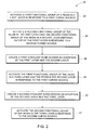
FIG. 1 is a cross-sectional view of a dual cure composite structure comprising a resin and illustrating cured layers of a resin with dual functional groups in accordance with embodiments of the present invention; -
FIG. 2 is a flow chart illustrating exemplary steps for a method of curing a dual cure composite structure illustrating a dual cure mechanism in accordance with certain embodiments of the present invention; -
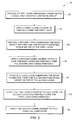
FIG. 3 is a flow chart illustrating exemplary steps for a method of manufacturing a dual cure composite structure comprising layers of resin with dual functional groups not in accordance with certain embodiments of the present invention; -
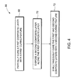
FIG. 4 is a flow chart illustrating exemplary steps for a method of manufacturing a composite structure with a dual cure mechanism in accordance with certain embodiments of the present invention; -
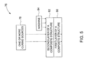
FIG. 5 is a block diagram of a manufacturing system used in a dual curing mechanism in a composite structure not in accordance with certain embodiments of the present invention; -
FIG. 6 is a diagrammatical illustration of an exemplary embodiment of the dual cure composite structure used in a wind turbine system comprising blades in accordance with embodiments of the present invention; and -
FIG. 7 is a diagrammatical illustration of the blades in the wind turbine system, such as illustrated inFIG. 6 , in accordance with certain embodiments of the present invention. - As discussed in detail below, various embodiments of the present invention provide a composite structure with a dual cure mechanism and a method of manufacturing the same. A dual cure composite structure used herein is defined as a composite structure having multiple layers, wherein the composite structure is manufactured using a "dual cure" mechanism to bond the multiple layers. "Dual cure" mechanism is a mechanism in which initially, a first layer is partially cured by a first curing feature followed by a second layer being disposed on top of the first layer. In a next step, the second layer is partially cured and the first layer is at least further or fully cured simultaneously by a second curing feature. In certain embodiments, the "dual cure" mechanism may be supplemented with one or more additional curing features, making the mechanism a generally "multi cure" mechanism. For example, the foregoing dual cure scenario may be supplemented by further applying a third layer on top of the second layer, and then partially curing the third layer and further or entirely curing the second layer simultaneously by a third curing feature. In this example, the first layer also may be further or entirely cured by the third curing feature simultaneous with the curing of the second and third layers. Similarly, a fourth, fifth, sixth, or additional layers may be successively applied over the composite structure, and successively cured in stages of partial, and eventually complete curing via two or more curing features (e.g., the first, second, or more curing features). Again, the curing features generally alternate (e.g., feature 1, 2, 1,2, etc.) as each successive layer is applied and simultaneously partially cured along with a previous layer. In this manner, the disclosed "dual cure" or "multi cure" mechanism may be described as "overlapping stages of curing" or "staged curing" or "step curing" of adjacent layers to create covalent bonds across interface of the layers and hence improve the interlayer adhesion.
- Rapid curing systems are desirable for large composite structures to obtain the desired manufacturing cycle time, reduce significant plant and equipment investment, and further decrease base cost of a part. This requires integration of appropriate resin chemistry with a corresponding curing source. In a system disclosed herein, for large composite structures, more than one independent curing source is introduced to activate a dual cure mechanism that will control a curing state and bonding between layers of the composite structure to achieve desirable mechanical properties. Curing source is a source used in curing layers of a composite structure. Non-limiting examples of a curing source are ultraviolet frequency radiation, or microwave frequency radiation, or radio frequency, or visible frequency radiation, or ultrasonic, or laser, or electron beam or a combination thereof.
- Turning now to the drawings,
FIG. 1 is a cross-sectional view of a dualcure composite structure 10 including afirst layer 12, asecond layer 14 and athird layer 16 of a resin or another material in accordance with embodiments of the present invention. As used herein, "resin" includes a resin or a resin blend. Thecomposite structure 10 may include two or more layers of a resin. In alternative embodiments, thecomposite structure 10 may include two or more layers of another type of material. Thefirst layer 12 includes a firstfunctional group 18 and a secondfunctional group 20. As used herein, the "functional group" is defined as an atom or a group of atoms in an organic compound that provides the compound with some of its characteristics which make it respond to a specific curing mechanism. Some non-limiting examples of functional groups include aldehydes, amines, hydroxyl, acrylate, methacrylate, vinyl, cyclo-epoxide, glycidyl etherepoxide with amine curatives, urethane, thiol-ene reactive group or a combination thereof. Some non-limiting examples of resins comprising these functional groups are unsaturated polyesters, vinyl esters, melamines, urea-formaledehydes, phenolics, methacrylates, acrylates, epoxies, urethanes, etc. Asecond layer 14 of the resin including the firstfunctional group 18 and the secondfunctional group 20 is disposed on thefirst layer 12. - Similarly, a
third layer 16 of the resin including the first 18 and the second 20 functional groups is disposed on thesecond layer 14 of the resin. The first 12 and the second 14 layers are bonded by a covalent bond formed at aninterface 22 of the two layers. Similarly, the second 14 and the third 16 layers are bonded by a covalent bond at aninterface 24 of the two layers. Further, in a non-limiting example, thecomposite structure 10 includes carbon, fiberglass, basalt fiber, and polymer fiber (such as polyethylene and polyimide) composites. Some non-limiting examples of the dual cure chemistry and curing sources are listed below:Table 1: Ex.1 Mechanism Functional Group/Curing Source Chemistry UV First Functional Group Curing Source 1 Acrylate+photoinitiator UV light thermal Second Functional Group Curing Source 2 Amine+epoxy Microwave or Infrared Ex.2 Mechanism Functional Group/Curing Source Chemistry UV First Functional Group Curing Source 1 Acrylate + photoinitiator UV light thermal Second Functional Group Curing Source 2 isocyanate + alcohol Microwave or Infrared Ex.3 Mechanism Functional Group/Curing Source Chemistry EB First Functional Group Curing Source 1 Epoxy + cationic catalyst EB thermal Second Functional Group Curing Source 2 isocyanate + alcohol Microwave or Infrared Ex.4 Mechanism Functional Group/Curing Source Chemistry EB First Functional Group Curing Source 1 Acrylate EB thermal Second Functional Group Curing Source 2 Amine + epoxy Microwave or Infrared Ex.5 Mechanism Functional Group/Curing Source Chemistry UV First Functional Group Curing Source 1 Acrylate + photoinitiator UV thermal Second Functional Group Curing Source 2 Amine + epoxy Microwave or Infrared Ex.6 Mechanism Functional Group/Curing Source Chemistry UV First Functional Group Curing Source 1 Epoxy + cationic photoinitiator UV thermal Second Functional Group Curing Source 2 Vinyl ester + peroxide Microwave or Infrared Ex.7 Mechanism Functional Group/Curing Source Chemistry UV First Functional Group Curing Source 1 Acrylate + photoinitiator 1 UV - Frequency 1 UV Second Functional Group Curing Source 2 Epoxy + cationic photoinitiator UV - Frequency 2 - Ex. 1 in Table 1 illustrates applying a curing source 1 (UV) source to initiate photo curing of the first functional group (acrylate) and applying curing source 2 (infrared) to thermally cure the second functional groups (epoxy with amine) according to the embodiment described in
Fig. 1 . Ex. 2-Ex. 7 follow similar lines. -
FIG. 2 illustrates amethod 30 of curing a dualcomposite structure 10 in accordance with the present invention. Themethod 30 includes activating a first functional group of a resin in a first layer in response to a first curing source atstep 32. Themethod 30 further includes activating a second functional group of the first layer and the second functional group of a second layer disposed on top of the first layer in response to a second curing source atstep 34. Following activation of the first functional group 18 (as referenced to inFIG.1 ) and the second functional group 20 (as referenced to inFIG. 1 ) of the first layer 12 (as referenced to inFIG. 1 ), the first layer may be fully cured. In certain embodiments, as noted above, the layers may include additional functional groups, such that the full curing of the layers may occur over three or more stages of curing with three or more curing sources. However, the illustrated embodiment includes two curing sources, such that each successive layer is generally completely cured in two stages. - Referring back to
FIG. 2 , activation of the secondfunctional group 20 of the second layer 14 (as referenced to inFIG. 1 ) results in partial curing of thesecond layer 14. These lead to creating a first covalent bond across an interface of the first layer and the second layer atstep 36. Themethod 30 further includes activating a first functional group of a third layer and the first functional group of the second layer in response to the first curing source atstep 38. This leads to a partially cured third layer 16 (as referenced to inFIG. 1 ) and a fully curedsecond layer 14. These result in creating a second covalent bond across an interface of the second layer and the third layer atstep 40. Themethod 30 further includes activating the second functional group of the third layer in response to the second curing source atstep 42. This leads to a fully curedthird layer 16. Simultaneous curing of two layers results in a stronger adhesive bonding than that formed via a single curing mechanism. This results in stronger interlaminar shear strengths and eliminates interlaminar property degradation. -
FIG. 3 illustrates anexemplary method 50 of manufacturing a dual curecomposite structure 10 as referenced to inFIG. 1 comprising a first 12, a second 14 and a third 16 layer of resin in accordance with certain embodiments of the present invention. The first 12, the second 14 and the third 16 layers further include a first 18 and a second 20 functional group as referenced inFIG. 1 . Themethod 50 includes providing a first layer comprising a resin having a first functional group and a second functional group asstep 52. Themethod 50 further includes applying a first curing source to partially cure the first layer atstep 54. The term 'partial curing' refers to curing less than about 100% of a layer of a composite structure. In certain embodiments, partial curing may be about 10, 20, 30, 40, 50, 60, 70, 80, or 90 percent, or some percentage between these values. In an exemplary embodiment, the partial curing may be between about 30-70 percent, or between 40-60 percent, or about 50 percent. However, the degree of partial curing may vary depending on the particular materials, curing source, layer thickness, and so forth. - Following partial curing of the first layer, the
method 50 includes providing a second layer comprising the resin having the first and the second functional group onto the first layer asstep 56. Following addition of the second layer, themethod 50 includes applying a second curing source to fully cure the first layer and partially cure the second layer simultaneously asstep 58. Thethird layer 16 may further be introduced by providing a third layer comprising the resin having the first and the second functional group onto the second layer asstep 60. Simultaneous curing of the second 14 and the third 16 layers occur by applying the first curing source to fully cure the second layer and partially cure the third layer simultaneously asstep 62. Full curing of thethird layer 16 occurs by applying the second curing source to fully cure the third layer asstep 64. -
FIG. 4 illustrates amethod 66 of manufacturing and curing a dual curecomposite structure 10 as referenced to inFIG. 1 including a first 12 and a second 14 layer. Themethod 66 includes partially curing a first composite layer with a first curing feature asstep 68. Following the partial curing, a secondcomposite layer 14 is introduced by disposing a second composite layer along the first composite layer asstep 70. Themethod 66 further includes simultaneously curing the first and second composite layers with a second curing feature to further cure the first composite layer and to partially cure the second composite layer, wherein the first and second curing features are different from one another asstep 72. The first and second curing features include different curing mechanisms, or the same curing mechanism having different output characteristics, or a combination of both. For example, several curing mechanisms and characteristics are described in further detail below. -
FIG. 5 illustrates amanufacturing system 76 used in a dual curing process of a dual curecomposite structure 10 as referenced inFIG. 1 . Themanufacturing system 76 comprises one ormore curing sources 78 configured to simultaneously cure afirst layer 80 and asecond layer 82 of the dual curecomposite structure 10. Themanufacturing system 76 further includes amachine 84 configured to dispose thesecond layer 82 on top of thefirst layer 80. Themachine 84 includes a machine that can be operated manually, or an automated machine, or a combination thereof. Themachine 84 may include a flat press, a roll press, hydraulics, springs, pneumatics, gear mechanisms, or other compressive mechanisms to force the layers toward one another. A non-limiting example of an automated machine includes an automated fiber and tape placement head and compaction roller. The one ormore curing sources 78 include an ultraviolet frequency radiation source, or a microwave frequency radiation source, or a radio frequency radiation source, or a visible frequency radiation source, or an ultrasonic radiation source, or an infrared, or a laser, or an electron beam or a combination thereof. The one ormore curing source 78 may include different curing types or different characteristics of the same curing type. In a non-limiting example, the one or more curing sources may include a single or two curing sources of the same type but emitting radiation (e.g., ultra-violet radiation) at different wavelengths, or frequencies. In another non-limiting example, the one or more curing sources may include two different types such as one curing source with ultra-violet radiation and a different curing source with microwave radiation, or one curing source with electron beam and one curing source with infrared radiation, or one curing source with microwave and one curing source with electron beam, or one curing source with UV-A and one curing source with UV-B, or once curing source with one microwave frequency C and one curing source with another microwave frequency. - Joining and assembling of piece-parts and subcomponents into monolithic structures is particularly advantageous and useful for modular design. Although both mechanical and adhesively bonded joints may be used, adhesive bonds generally provide for lower weight designs and a desirable strength. The disclosed dual curing mechanism provides a desirable strength and potential for adhesive bonds in composite structures comprising resins as described in previous paragraphs. Composite structures including resins may be used as materials in mechanical components for desirable adhesive bonding during joining and assembling of mechanical components.
-
FIG. 6 is a diagrammatical illustration of an exemplary embodiment of a dualcomposite structure 10 as referenced to inFIG. 1 , illustrating awind turbine system 90 in accordance with embodiments of the present invention. Some of the characteristics that make composites, such as carbon and fiberglass composites, suitable for wind turbine blades are desirable mechanical properties, tailorability of material properties, and versatility of fabrication methods. In addition, the carbon and fiberglass composites provide desirable toughness and shorter process cycle time than that known in existing manufacturing processes. Thewind turbine system 90 includes a plurality of blades 92 (e.g., three blades). Theblades 92 enable thesystem 90 to capture energy from the wind. Specifically, the wind forces theblades 92 to rotate about an axis, thereby driving an electrical generator disposed within thesystem 90. Long blades are desirable since it provides a big lever to capture desirable amounts of energy. In a non-limiting example, theblades 92 of thewind turbine system 90 have a typical length of about 70 meters to maximize capture of energy and reduce cost of energy. Components of theblade 92 may comprise the dual curecomposite structure 10 as discussed below. Theblades 92 are coupled to atower 94. The height of the tower, which determines height of thewind turbine system 90, plays a significant part in design of thewind turbine system 90. Due to change in velocity of wind with altitude, also known as wind shear, an optimum height is desirable for optimum performance of thewind turbine system 90. Generally, height of thetower 94 is about two to three times length of theblades 92 for an optimal performance. -
FIG. 7 illustrates a modular design of ablade 92 as referenced inFIG. 6 of awind turbine system 90 in accordance with certain embodiments of the present invention. The illustratedblade 92 includes atop skin 96 and ashear web 98 disposed between a pair of spar caps 100 that are coupled to abarrel 102. Theshear web 98 provides desirable strength to theblade 92 and also provides desirable support to the pair of spar caps 100. Theblade 92 further includes abottom skin 104 disposed below theshear web 98. The pair of spar caps 100 is made of adual cure composite 10, such as a carbon and a fiberglass composite. Since theblade 92 is a significant component of the windturbine blade system 90 as referenced to inFIG.6 , using a dual curecomposite structure 10 as referenced to inFIG. 1 and described in the aforementioned embodiments, provides desirable mechanical strength to theturbine blade system 90. Further, thetop skin 96 and thebottom skin 104 may comprise the dual curecomposite structure 10. -
- 10
- Dual cure system
- 12
- a first layer
- 14
- a first functional group
- 16
- a second functional group
- 18
- a second layer
- 20
- a third layer
- 22
- a first covalent bond
- 24
- a second covalent bond
- 30
- Method of curing
- 32
- activate a first functional group of a resin in a first layer in response to a first curing source
- 34
- activate a second functional group of a resin in the first layer and the second functional group of a second layer disposed on top of the first layer in response to a second curing source
- 36
- create a first covalent bond across an interface of the first layer and the second layer
- 38
- activate the first functional group of a third layer and the second layer in response to the first curing source;
- 40
- create a second covalent bond across an interface of the second layer and the third layer
- 42
- activate the second functional group of a fourth layer in response to the second curing source
- 50
- Method of manufacturing
- 52
- provide a first layer comprising a resin with a first and a second functional group
- 54
- apply a first curing source to partially cure the first layer
- 56
- provide a second layer comprising the resin with the first and the second functional group on top of the first layer
- 58
- apply a second curing source to fully cure the first layer and partially cure the second layer simultaneously
- 60
- provide a third layer comprising the resin with the first and the second functional group on top of the second layer
- 62
- apply the first curing source to fully cure the second layer and partially cure the third layer simultaneously
- 64
- apply the second curing source to fully cure the third layer
- 66
- Method
- 68
- partially cure a first composite layer with a first curing feature
- 70
- dispose a second composite layer along the first composite layer
- 71
- simultaneously cure the first and second composite layers with a second curing feature
- 76
- manufacturing system
- 78
- One or more curing sources
- 80
- First layer of a composite structure
- 82
- Second layer of a composite structure
- 84
- Machine
- 90
- Wind turbine blade system
- 92
- Blade
- 94
- Tower
- 96
- top skin
- 98
- Shear web
- 100
- spar caps
- 102
- barrel
- 104
- bottom skin
Claims (3)
- A method (30), comprising:activating a first functional group (18) of a resin in a first layer (12) in response to a first curing source;activating a second functional group (20) of the resin in the first layer (12) and the second functional group (20) of the resin in a second layer (14) disposed on the first layer (12) in response to a second curing source, wherein the first and second functional groups are different from one another, and the first and second curing sources comprise curing features that are different from one another;creating a first covalent bond (22) across an interface of the first layer (12) and the second layer (14);activating the first functional group (18) of the resin in a third layer (16) and the resin in a second layer (14) in response to the first curing source;creating a second covalent bond (24) across an interface of the second layer (14) and the third layer (16); andactivating the second functional group (20) of the resin in the third layer (16) in response to the second curing source.
- The method of claim 1, further comprising activating the first (18) and the second functional group (20) of the resin in more than two layers.
- The method of claim 1 or claim 2, wherein the first curing source and the second curing source comprise radiations at different frequencies.
Applications Claiming Priority (1)
| Application Number | Priority Date | Filing Date | Title |
|---|---|---|---|
| US11/403,674 US20070243387A1 (en) | 2006-04-13 | 2006-04-13 | Dual cure resin composite system and method of manufacturing the same |
Publications (3)
| Publication Number | Publication Date |
|---|---|
| EP1845126A2 EP1845126A2 (en) | 2007-10-17 |
| EP1845126A3 EP1845126A3 (en) | 2009-05-20 |
| EP1845126B1 true EP1845126B1 (en) | 2013-08-14 |
Family
ID=38226608
Family Applications (1)
| Application Number | Title | Priority Date | Filing Date |
|---|---|---|---|
| EP20070105592 Not-in-force EP1845126B1 (en) | 2006-04-13 | 2007-04-04 | Dual cure resin composite system and method of manufacturing the same |
Country Status (7)
| Country | Link |
|---|---|
| US (2) | US20070243387A1 (en) |
| EP (1) | EP1845126B1 (en) |
| CN (1) | CN101100120B (en) |
| BR (1) | BRPI0701379B1 (en) |
| DK (1) | DK1845126T3 (en) |
| ES (1) | ES2431663T3 (en) |
| MX (1) | MX2007004389A (en) |
Families Citing this family (17)
| Publication number | Priority date | Publication date | Assignee | Title |
|---|---|---|---|---|
| US20070066698A1 (en) | 2005-09-20 | 2007-03-22 | Yang Wenliang P | Dual cure compositions, methods of curing thereof and articles therefrom |
| US8221085B2 (en) * | 2007-12-13 | 2012-07-17 | General Electric Company | Wind blade joint bonding grid |
| BR112012017122B1 (en) | 2010-01-14 | 2021-09-28 | Senvion Gmbh | COMPOSITE BEAM FOR A WIND TURBINE SHOVEL |
| US10137542B2 (en) | 2010-01-14 | 2018-11-27 | Senvion Gmbh | Wind turbine rotor blade components and machine for making same |
| US8541687B2 (en) * | 2010-04-22 | 2013-09-24 | Endicott Interconnect Technologies, Inc. | Coreless layer buildup structure |
| US8536459B2 (en) * | 2010-04-22 | 2013-09-17 | Endicott Interconnect Technologies, Inc. | Coreless layer buildup structure with LGA |
| US9351408B2 (en) * | 2010-04-22 | 2016-05-24 | I3 Electronics, Inc. | Coreless layer buildup structure with LGA and joining layer |
| CN101830096A (en) * | 2010-05-14 | 2010-09-15 | 上海飞域实验室设备有限公司 | Manufacturing method of composite epoxy resin countertop |
| US20120247822A1 (en) * | 2011-03-28 | 2012-10-04 | Endicott Interconnect Technologies, Inc. | Coreless layer laminated chip carrier having system in package structure |
| US8360732B2 (en) | 2011-05-25 | 2013-01-29 | General Electric Company | Rotor blade section and method for assembling a rotor blade for a wind turbine |
| DE102011077612A1 (en) * | 2011-06-16 | 2012-12-20 | Evonik Röhm Gmbh | Process for the continuous inline production of coated polymeric substrates or laminates |
| US20120138223A1 (en) | 2011-09-29 | 2012-06-07 | General Electric Company | Uv-ir combination curing system and method of use for wind blade manufacture and repair |
| US9297357B2 (en) | 2013-04-04 | 2016-03-29 | General Electric Company | Blade insert for a wind turbine rotor blade |
| US9506452B2 (en) | 2013-08-28 | 2016-11-29 | General Electric Company | Method for installing a shear web insert within a segmented rotor blade assembly |
| KR102339967B1 (en) * | 2013-11-06 | 2021-12-17 | 세키스이가가쿠 고교가부시키가이샤 | Method for manufacturing cured film, method for manufacturing electronic component, and electronic component |
| US10357960B2 (en) * | 2015-10-30 | 2019-07-23 | Nike, Inc. | Three-dimensional curing of a two-dimensionally printed object |
| CN110561874A (en) * | 2019-09-19 | 2019-12-13 | 常州市天润木业有限公司 | preparation process of novel warm soft surface plate |
Family Cites Families (14)
| Publication number | Priority date | Publication date | Assignee | Title |
|---|---|---|---|---|
| US3574040A (en) * | 1967-06-29 | 1971-04-06 | Gen Dynamics Corp | Apparatus for making laminated structural shapes by the controlled detrusive placement and polymerization of tectonic filamentous tapes |
| US4265723A (en) * | 1979-07-06 | 1981-05-05 | Basf Aktiengesellschaft | Photocurable molding, impregnating and coating compositions |
| JPS5752052A (en) * | 1980-09-12 | 1982-03-27 | Fujitsu Ltd | Heat treatment of photosensitive resin |
| US4642321A (en) * | 1985-07-19 | 1987-02-10 | Kollmorgen Technologies Corporation | Heat activatable adhesive for wire scribed circuits |
| US6432236B1 (en) * | 1991-03-01 | 2002-08-13 | Foster-Miller, Inc. | Ultrasonic method of fabricating a thermosetting matrix fiber-reinforced composite structure and the product thereof |
| FR2765346B1 (en) * | 1997-06-26 | 1999-09-24 | Alsthom Cge Alcatel | METHOD FOR MANUFACTURING AN OPTICAL CONDUCTOR |
| US6038464A (en) * | 1998-02-09 | 2000-03-14 | Axelgaard Manufacturing Co., Ltd. | Medical electrode |
| US6709717B2 (en) | 1998-06-09 | 2004-03-23 | Margrace Enterprises, Inc. | Method for making polymer surfaced composites |
| US6652943B2 (en) * | 2001-06-04 | 2003-11-25 | Saint-Gobain Performance Plastics Corporation | Multilayer polymeric article with intercrosslinked polymer layers and method of making same |
| US6835759B2 (en) * | 2001-08-28 | 2004-12-28 | Basf Corporation | Dual cure coating composition and processes for using the same |
| DE10201420A1 (en) * | 2002-01-15 | 2003-07-24 | Basf Ag | Highly adhesive mixture especially for coating plastics, glass or metals comprises a radiation-hardenable composition with an added adhesive |
| DE10248324A1 (en) | 2002-10-17 | 2004-05-06 | Basf Coatings Ag | Coating material curable thermally and with actinic radiation and process for coating micropoporous surfaces |
| EP1645607A1 (en) * | 2004-10-05 | 2006-04-12 | Kun-Chung Liu | Method for preparing a logo label |
| US7390559B2 (en) * | 2004-10-22 | 2008-06-24 | Ppg Industries Ohio, Inc. | Multilayer coating system |
-
2006
- 2006-04-13 US US11/403,674 patent/US20070243387A1/en not_active Abandoned
-
2007
- 2007-04-04 DK DK07105592T patent/DK1845126T3/en active
- 2007-04-04 ES ES07105592T patent/ES2431663T3/en active Active
- 2007-04-04 EP EP20070105592 patent/EP1845126B1/en not_active Not-in-force
- 2007-04-10 BR BRPI0701379-5A patent/BRPI0701379B1/en not_active IP Right Cessation
- 2007-04-12 MX MX2007004389A patent/MX2007004389A/en active IP Right Grant
- 2007-04-13 CN CN2007101097998A patent/CN101100120B/en not_active Expired - Fee Related
-
2010
- 2010-07-01 US US12/828,316 patent/US9556315B2/en not_active Expired - Fee Related
Also Published As
| Publication number | Publication date |
|---|---|
| BRPI0701379A (en) | 2007-12-11 |
| EP1845126A2 (en) | 2007-10-17 |
| MX2007004389A (en) | 2009-02-16 |
| DK1845126T3 (en) | 2013-10-21 |
| US20100272574A1 (en) | 2010-10-28 |
| CN101100120B (en) | 2013-10-23 |
| ES2431663T3 (en) | 2013-11-27 |
| BRPI0701379B1 (en) | 2018-01-30 |
| US9556315B2 (en) | 2017-01-31 |
| EP1845126A3 (en) | 2009-05-20 |
| CN101100120A (en) | 2008-01-09 |
| US20070243387A1 (en) | 2007-10-18 |
Similar Documents
| Publication | Publication Date | Title |
|---|---|---|
| US9556315B2 (en) | Dual cure resin composite system and method of manufacturing the same | |
| DK178163B1 (en) | UV-IR combination curing system and method of use for wind blade manufacture and repair | |
| CA2685478C (en) | Integrated multispar torsion box of composite material | |
| US10093778B2 (en) | Bonding composite structures using interpenetrating polymer network adhesives | |
| AU2003263241B2 (en) | Method for making a soundproofing panel with at least one double resonator | |
| EP2708572A1 (en) | UV Curing System and Method for Wind Blade Manufacture and Repair | |
| JP2001510746A (en) | Method of assembling large-sized parts such as aircraft fuselage made of composite material having thermoplastic matrix | |
| KR20030069113A (en) | Methods of manufacturing a stiffening element for an aircraft skin panel and a skin panel provided with the stiffening element | |
| US20220258432A1 (en) | Methods of fabrication of composite repair parts and related kits | |
| US20090041985A1 (en) | Composite fibre component with thermoplastic stiffening elements | |
| WO2010022247A1 (en) | Flat-cured composite structure | |
| US20140220839A1 (en) | Out-of-Autoclave Curing System | |
| CA2865110C (en) | Composite structures using interpenetrating polymer network adhesives | |
| US7083753B2 (en) | Honeycomb core composite article and method and apparatus for making same | |
| JP7034849B2 (en) | Composite material, method for manufacturing composite material, and method for curing composite material | |
| EP2971397B1 (en) | Balsawood cores for composite material sandwich panels and method of their manufacture | |
| US9464217B2 (en) | Composite structures using interpenetrating polymer network adhesives | |
| JP6681622B2 (en) | Method for manufacturing wood laminate | |
| NL2031608B1 (en) | A method to fabricate a thin-walled structure | |
| HK1161892B (en) | Composite structures using interpenetrating polymer network adhesives | |
| Scherrer et al. | Design and Fabrication of a Low-Cost Composite Spaceframe Spacecraft Structure | |
| HK1161892A (en) | Composite structures using interpenetrating polymer network adhesives |
Legal Events
| Date | Code | Title | Description |
|---|---|---|---|
| PUAI | Public reference made under article 153(3) epc to a published international application that has entered the european phase |
Free format text: ORIGINAL CODE: 0009012 |
|
| AK | Designated contracting states |
Kind code of ref document: A2 Designated state(s): AT BE BG CH CY CZ DE DK EE ES FI FR GB GR HU IE IS IT LI LT LU LV MC MT NL PL PT RO SE SI SK TR |
|
| AX | Request for extension of the european patent |
Extension state: AL BA HR MK YU |
|
| PUAL | Search report despatched |
Free format text: ORIGINAL CODE: 0009013 |
|
| AK | Designated contracting states |
Kind code of ref document: A3 Designated state(s): AT BE BG CH CY CZ DE DK EE ES FI FR GB GR HU IE IS IT LI LT LU LV MC MT NL PL PT RO SE SI SK TR |
|
| AX | Request for extension of the european patent |
Extension state: AL BA HR MK RS |
|
| 17P | Request for examination filed |
Effective date: 20091120 |
|
| AKX | Designation fees paid |
Designated state(s): DE DK ES GB NL |
|
| 17Q | First examination report despatched |
Effective date: 20100127 |
|
| GRAP | Despatch of communication of intention to grant a patent |
Free format text: ORIGINAL CODE: EPIDOSNIGR1 |
|
| GRAS | Grant fee paid |
Free format text: ORIGINAL CODE: EPIDOSNIGR3 |
|
| GRAA | (expected) grant |
Free format text: ORIGINAL CODE: 0009210 |
|
| AK | Designated contracting states |
Kind code of ref document: B1 Designated state(s): DE DK ES GB NL |
|
| REG | Reference to a national code |
Ref country code: GB Ref legal event code: FG4D |
|
| REG | Reference to a national code |
Ref country code: DE Ref legal event code: R096 Ref document number: 602007032194 Country of ref document: DE Effective date: 20131010 |
|
| REG | Reference to a national code |
Ref country code: DK Ref legal event code: T3 |
|
| REG | Reference to a national code |
Ref country code: NL Ref legal event code: T3 |
|
| REG | Reference to a national code |
Ref country code: ES Ref legal event code: FG2A Ref document number: 2431663 Country of ref document: ES Kind code of ref document: T3 Effective date: 20131127 |
|
| PLBE | No opposition filed within time limit |
Free format text: ORIGINAL CODE: 0009261 |
|
| STAA | Information on the status of an ep patent application or granted ep patent |
Free format text: STATUS: NO OPPOSITION FILED WITHIN TIME LIMIT |
|
| 26N | No opposition filed |
Effective date: 20140515 |
|
| REG | Reference to a national code |
Ref country code: DE Ref legal event code: R097 Ref document number: 602007032194 Country of ref document: DE Effective date: 20140515 |
|
| PGFP | Annual fee paid to national office [announced via postgrant information from national office to epo] |
Ref country code: NL Payment date: 20180426 Year of fee payment: 12 |
|
| PGFP | Annual fee paid to national office [announced via postgrant information from national office to epo] |
Ref country code: DE Payment date: 20180427 Year of fee payment: 12 Ref country code: ES Payment date: 20180503 Year of fee payment: 12 Ref country code: DK Payment date: 20180426 Year of fee payment: 12 |
|
| PGFP | Annual fee paid to national office [announced via postgrant information from national office to epo] |
Ref country code: GB Payment date: 20180427 Year of fee payment: 12 |
|
| REG | Reference to a national code |
Ref country code: DE Ref legal event code: R119 Ref document number: 602007032194 Country of ref document: DE |
|
| REG | Reference to a national code |
Ref country code: DK Ref legal event code: EBP Effective date: 20190430 |
|
| REG | Reference to a national code |
Ref country code: NL Ref legal event code: MM Effective date: 20190501 |
|
| GBPC | Gb: european patent ceased through non-payment of renewal fee |
Effective date: 20190404 |
|
| PG25 | Lapsed in a contracting state [announced via postgrant information from national office to epo] |
Ref country code: GB Free format text: LAPSE BECAUSE OF NON-PAYMENT OF DUE FEES Effective date: 20190404 Ref country code: DE Free format text: LAPSE BECAUSE OF NON-PAYMENT OF DUE FEES Effective date: 20191101 Ref country code: NL Free format text: LAPSE BECAUSE OF NON-PAYMENT OF DUE FEES Effective date: 20190501 |
|
| PG25 | Lapsed in a contracting state [announced via postgrant information from national office to epo] |
Ref country code: DK Free format text: LAPSE BECAUSE OF NON-PAYMENT OF DUE FEES Effective date: 20190430 |
|
| REG | Reference to a national code |
Ref country code: ES Ref legal event code: FD2A Effective date: 20200828 |
|
| PG25 | Lapsed in a contracting state [announced via postgrant information from national office to epo] |
Ref country code: ES Free format text: LAPSE BECAUSE OF NON-PAYMENT OF DUE FEES Effective date: 20190405 |
|
| P01 | Opt-out of the competence of the unified patent court (upc) registered |
Effective date: 20230522 |