EP1845043A1 - Conveying apparatus and image forming apparatus - Google Patents
Conveying apparatus and image forming apparatus Download PDFInfo
- Publication number
- EP1845043A1 EP1845043A1 EP06027097A EP06027097A EP1845043A1 EP 1845043 A1 EP1845043 A1 EP 1845043A1 EP 06027097 A EP06027097 A EP 06027097A EP 06027097 A EP06027097 A EP 06027097A EP 1845043 A1 EP1845043 A1 EP 1845043A1
- Authority
- EP
- European Patent Office
- Prior art keywords
- guide
- sheet
- curved
- conveying apparatus
- convey path
- Prior art date
- Legal status (The legal status is an assumption and is not a legal conclusion. Google has not performed a legal analysis and makes no representation as to the accuracy of the status listed.)
- Granted
Links
- 229920003002 synthetic resin Polymers 0.000 claims abstract description 18
- 239000000057 synthetic resin Substances 0.000 claims abstract description 18
- XECAHXYUAAWDEL-UHFFFAOYSA-N acrylonitrile butadiene styrene Chemical compound C=CC=C.C=CC#N.C=CC1=CC=CC=C1 XECAHXYUAAWDEL-UHFFFAOYSA-N 0.000 claims description 8
- 229920000122 acrylonitrile butadiene styrene Polymers 0.000 claims description 8
- 239000004676 acrylonitrile butadiene styrene Substances 0.000 claims description 8
- 239000000463 material Substances 0.000 claims description 8
- 229920006324 polyoxymethylene Polymers 0.000 claims description 7
- 229930182556 Polyacetal Natural products 0.000 claims description 3
- 239000004793 Polystyrene Substances 0.000 claims 1
- 229920002223 polystyrene Polymers 0.000 claims 1
- 239000000976 ink Substances 0.000 description 15
- 238000010276 construction Methods 0.000 description 8
- 230000006870 function Effects 0.000 description 8
- 230000003247 decreasing effect Effects 0.000 description 7
- 238000011144 upstream manufacturing Methods 0.000 description 6
- 230000000052 comparative effect Effects 0.000 description 5
- 230000007423 decrease Effects 0.000 description 5
- 229920005989 resin Polymers 0.000 description 5
- 239000011347 resin Substances 0.000 description 5
- 230000005540 biological transmission Effects 0.000 description 4
- 239000002131 composite material Substances 0.000 description 4
- 230000002829 reductive effect Effects 0.000 description 4
- 239000000758 substrate Substances 0.000 description 4
- 229920005177 Duracon® POM Polymers 0.000 description 3
- 230000002093 peripheral effect Effects 0.000 description 3
- 230000002411 adverse Effects 0.000 description 2
- 239000004020 conductor Substances 0.000 description 2
- 229920005669 high impact polystyrene Polymers 0.000 description 2
- 239000004797 high-impact polystyrene Substances 0.000 description 2
- 230000003068 static effect Effects 0.000 description 2
- 235000010724 Wisteria floribunda Nutrition 0.000 description 1
- 238000009825 accumulation Methods 0.000 description 1
- 230000001154 acute effect Effects 0.000 description 1
- 230000008859 change Effects 0.000 description 1
- 238000007599 discharging Methods 0.000 description 1
- 230000005611 electricity Effects 0.000 description 1
- 239000004973 liquid crystal related substance Substances 0.000 description 1
- 230000004048 modification Effects 0.000 description 1
- 238000012986 modification Methods 0.000 description 1
- 229920006267 polyester film Polymers 0.000 description 1
- 230000002441 reversible effect Effects 0.000 description 1
- 230000001360 synchronised effect Effects 0.000 description 1
Images


Classifications
-
- B—PERFORMING OPERATIONS; TRANSPORTING
- B65—CONVEYING; PACKING; STORING; HANDLING THIN OR FILAMENTARY MATERIAL
- B65H—HANDLING THIN OR FILAMENTARY MATERIAL, e.g. SHEETS, WEBS, CABLES
- B65H3/00—Separating articles from piles
- B65H3/02—Separating articles from piles using friction forces between articles and separator
- B65H3/06—Rollers or like rotary separators
-
- B—PERFORMING OPERATIONS; TRANSPORTING
- B65—CONVEYING; PACKING; STORING; HANDLING THIN OR FILAMENTARY MATERIAL
- B65H—HANDLING THIN OR FILAMENTARY MATERIAL, e.g. SHEETS, WEBS, CABLES
- B65H3/00—Separating articles from piles
- B65H3/66—Article guides or smoothers, e.g. movable in operation
- B65H3/68—Article guides or smoothers, e.g. movable in operation immovable in operation
-
- G—PHYSICS
- G03—PHOTOGRAPHY; CINEMATOGRAPHY; ANALOGOUS TECHNIQUES USING WAVES OTHER THAN OPTICAL WAVES; ELECTROGRAPHY; HOLOGRAPHY
- G03G—ELECTROGRAPHY; ELECTROPHOTOGRAPHY; MAGNETOGRAPHY
- G03G15/00—Apparatus for electrographic processes using a charge pattern
- G03G15/65—Apparatus which relate to the handling of copy material
- G03G15/6555—Handling of sheet copy material taking place in a specific part of the copy material feeding path
- G03G15/6558—Feeding path after the copy sheet preparation and up to the transfer point, e.g. registering; Deskewing; Correct timing of sheet feeding to the transfer point
-
- B—PERFORMING OPERATIONS; TRANSPORTING
- B65—CONVEYING; PACKING; STORING; HANDLING THIN OR FILAMENTARY MATERIAL
- B65H—HANDLING THIN OR FILAMENTARY MATERIAL, e.g. SHEETS, WEBS, CABLES
- B65H2404/00—Parts for transporting or guiding the handled material
- B65H2404/50—Surface of the elements in contact with the forwarded or guided material
- B65H2404/53—Surface of the elements in contact with the forwarded or guided material with particular mechanical, physical properties
- B65H2404/531—Surface of the elements in contact with the forwarded or guided material with particular mechanical, physical properties particular coefficient of friction
- B65H2404/5311—Surface with different coefficients of friction
-
- G—PHYSICS
- G03—PHOTOGRAPHY; CINEMATOGRAPHY; ANALOGOUS TECHNIQUES USING WAVES OTHER THAN OPTICAL WAVES; ELECTROGRAPHY; HOLOGRAPHY
- G03G—ELECTROGRAPHY; ELECTROPHOTOGRAPHY; MAGNETOGRAPHY
- G03G15/00—Apparatus for electrographic processes using a charge pattern
- G03G15/14—Apparatus for electrographic processes using a charge pattern for transferring a pattern to a second base
- G03G15/16—Apparatus for electrographic processes using a charge pattern for transferring a pattern to a second base of a toner pattern, e.g. a powder pattern, e.g. magnetic transfer
- G03G15/1665—Apparatus for electrographic processes using a charge pattern for transferring a pattern to a second base of a toner pattern, e.g. a powder pattern, e.g. magnetic transfer by introducing the second base in the nip formed by the recording member and at least one transfer member, e.g. in combination with bias or heat
Abstract
Description
- The present application is based on
Japanese Patent Application No. 2005-380595 - The present invention relates to a conveying apparatus that conveys a flexible sheet such as a recording sheet through a sheet-convey path including a curved portion defined by opposed guide members, from a sheet-supply portion to a sheet-discharge portion for holding and discharging the sheet conveyed.
- There has been known a printer employing a conveying apparatus that conveys a recording sheet through a so-called "U-turn" path. For example, Patent Document 1 (
Japanese Patent Application Publication No. 2002-249248 - In addition, Patent Document 2 (
Japanese Patent Application Publication No. 2002-247544 - When the recording sheet is conveyed along the U-turn path, the sheet is guided by the curved guide member(s) while being curved or flexed. More specifically described, the recording sheet is conveyed while being slid on the outer guide member or portion. Therefore, a friction is produced between the recording sheet and the outer guide member or portion. In particular, in the case where a thick recording sheet such as a postcard, or a sheet whose surface is treated with a material giving a high frictional resistance, such as a glossy paper, is conveyed, an increased friction is produced between the recording sheet and the outer guide member. Consequently the speed of conveying of the recording sheet may be made unstable, or even zeroed because the frictional force overcomes the conveying force.
- In the above-identified background, the present invention has been developed. It is therefore an object of the present invention to solve at least one of the above-identified problems. It is another object of the present invention to provide the art of reliably lowering a friction produced between a flexible sheet and a guide member when the sheet is conveyed in a sheet-convey path including a curved portion.
- According to a first aspect of the present invention, there is provided a conveying apparatus for conveying a flexible sheet along a sheet-convey path including a curved portion. The conveying apparatus comprises an outer guide which defines an outer portion of the curved portion of the sheet-convey path. The outer guide includes at least one curved plate having a first curved guide surface which contacts and guides the flexible sheet; and a guide base including at least one holding portion which holds the at least one curved plate. The at least one curved plate is formed of a synthetic resin assuring that the first curved guide surface thereof has a first frictional resistance lower than a second frictional resistance of a surface of the guide base.
- In the present conveying apparatus, the flexible sheet is conveyed through the sheet-convey path. The sheet-convey path includes the curved portion, and the conveying apparatus comprises the outer guide defining the outer portion of the curved portion of the sheet-convey path. The outer guide includes the at least one curved plate having the first curved guide surface which contacts and guides the flexible sheet. The flexible sheet is conveyed by being guided by the first curved guide surface, while the sheet is deformed or flexed. The outer guide additionally includes the guide base including the at least one holding portion that holds the at least one curved plate. The at least one curved plate is formed of the synthetic resin assuring that the first curved guide surface thereof has the first frictional resistance lower than the second frictional resistance of the surface of the guide base. Since the first curved guide surface has the low frictional resistance, the flexible sheet can be conveyed smoothly. In addition, the guide base may be formed of a material that is advantageous with respect to formability and/or appearance than with respect to frictional resistance. Therefore, the outer guide can enjoy a low frictional resistance and a good external appearance.
- According to a second aspect of the present invention, there is provided an image forming apparatus, comprising the conveying apparatus according to the first aspect of the invention; and an image forming portion which is provided in the sheet-convey path and which forms an image on the flexible sheet conveyed along the sheet-convey path by the conveying apparatus.
- The present image forming apparatus enjoys the same advantages as those described above with respect to the conveying apparatus in accordance with the first aspect of the invention.
- The above and optional objects, features, and advantages of the present invention will be better understood by reading the following detailed description of the preferred embodiments of the invention when considered in conjunction with the accompanying drawings, in which:
- Fig. 1 is a perspective view showing an external construction of a multi-function device (MFD) 1 to which the present invention is applied;
- Fig. 2 is a cross-sectional view showing an internal construction of the
MFD 1; - Fig. 3 is an enlarged, cross-sectional view showing a relevant portion of a
printer portion 2 of theMFD 1; - Fig. 4 is a plan view showing the relevant portion of the
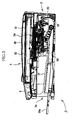
printer portion 2; - Fig. 5 is a perspective view showing a construction of an
outer guide 18; - Fig. 6 is an exploded, perspective view of the
outer guide 18; - Fig. 7 is a perspective view showing a first guide surface of a
guide cover 102 of theouter guide 18; - Fig. 8 is a perspective view showing a rear surface of the
guide cover 102; - Fig. 9 is a side elevation view of the
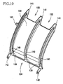
guide cover 102; - Fig. 10 is a perspective view of a
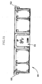
guide plate 104 of theouter guide 18; and - Fig. 11 is a rear elevation view of a
guide base 101 of theouter guide 18, as viewed along anarrow 160 in Fig. 5. - Hereinafter, there will be described preferred embodiments of the present invention by reference to the drawings.
- Fig. 1 shows an external appearance of a "multi-function device (MFD)" 1; and Fig. 2 shows an internal construction of the
MFD 1. The MFD 1 has a printer function, a scanner function, a copier function, and a facsimile-machine function, and includes aprinter portion 2 provided in a lower portion thereof, and a scanner portion 3 provided in an upper portion thereof that is integral with the lower portion. In theMFD 1, theprinter portion 2 corresponds to an image forming apparatus to which the present invention is applied, and accordingly the functions other than the printer function may be omitted. That is, the present invention may be applied to a single-function printer that has only the printer function and does not have the scanner, copier, or facsimile-machine function. For example, the scanner portion 3 may be omitted from theMFD 1. In addition, theprinter portion 2 employs a conveying apparatus to which the present invention is also applied. However, theprinter portion 2 is just an example that employs the conveying apparatus of the present invention. That is, the conveying apparatus of the present invention may be applied to other sorts of apparatuses than theprinter portion 2 as the image forming apparatus. For example, the scanner portion 3 as an image reading apparatus may employ, as a portion of an automatic document feed (ADF) thereof, the conveying apparatus of the present invention. - As shown in Fig. 1, a length and a width of the
MFD 1 are greater than a height thereof. Thus, the MFD 1 has a flat appearance with a generally rectangular parallelepiped shape. In the lower portion of theMFD 1, there is provided theprinter portion 2. Theprinter portion 2 has afront opening 2a formed in a front surface of theMFD 1, and additionally has a sheet-supply tray 20 as a sheet-supply portion and a sheet-discharge tray 21 as a sheet-discharge portion both of which are exposed through thefront opening 2a such that the sheet-discharge tray 21 is provided above the sheet-supply tray 20. The sheet-supply tray 20 is for storing a plurality of recording sheets each as a flexible sheet, and can accommodate sheets of various sizes not larger than A4 Size, such as A4 Size, B5 Size, or Postcard Size. As shown in Fig. 2, the sheet-supply tray 20 includes aslideable member 20a that is extensible to increase a bottom-surface area of thetray 20, so that thetray 20 can accommodate Legal-Size recording sheets. As will be described later, the recording sheets stored by the sheet-supply tray 20 are supplied, one by one, to animage recording unit 24 of theprinter portion 2, so that a desired image is recorded on each recording sheet and then the each recording sheet is discharged onto the sheet-discharge tray 21. In the present embodiment, the conveying apparatus conveys the recording sheets. However, the conveying apparatus may convey other sorts of flexible sheets, such as a synthetic-resin sheet, that can be conveyed along a curved sheet-convey path. Theimage recording unit 24 corresponds to an image forming portion of the image forming apparatus. - An operation panel 4 is provided in a front end portion of the upper portion of the
MFD 1. The operation panel 4 is for operating theprinter portion 2 and the scanner portion 3. The operation panel 4 includes various operation keys and a liquid crystal display (LCD) that are usable by a user to input various commands to operate theMFD 1. In the case where theMFD 1 is connected to an external computer such as a personal computer (PC), theMFD 1 is operated according to commands supplied from the external computer via a printer driver or a scanner driver. TheMFD 1 has, in a left, top portion of the front surface thereof (Fig. 1), aslot portion 5 into which each of various sorts of small-size memory cards each as a recording medium can be inserted. When the operation panel 4 is operated by the user in an appropriate manner, theMFD 1 reads image data stored by the memory card inserted in theslot portion 5, and the LCD of the operation panel 4 displays, based on the thus read image data, information related to the image data. Thus, the user can select, by operating the keys of the operation panel 4, one or more desired images from the image data, so that theprinter portion 2 may record or print the image(s) on the recording sheet(s). - Hereinafter, the internal construction of the
MFD 1, in particular, the construction of theprinter portion 2 will be described by reference to Figs. 2 through 8. As shown in Figs. 2 and 3, the sheet-supply tray 20, provided in the bottom portion of theMFD 1, has an inclined sheet-separate plate 22 provided in a downstream-side end portion thereof with respect to a sheet-supply direction in which each recording sheet is supplied from thetray 20. The inclined sheet-separate plate 22 is for separating each of the recording sheets stacked in the sheet-supply tray 20, from the other recording sheets, and guiding a movement of the separated recording sheet in an upward direction toward a sheet-conveypath 23. As shown in Fig. 3, the sheet-conveypath 23 first extends upward from the sheet-separate plate 22, then curves toward the front side (i.e., left side in the figure) of theMFD 1, and further extends to thefront opening 2a. That is, the sheet-conveypath 23 extends from the rear side of theMFD 1 toward the front side thereof via theimage recording unit 24 and the sheet-discharge tray 21. Thus, the sheet-conveypath 23 includes a U-turn portion through which the direction of supplying of each recording sheet is reversed from the rearward direction to the frontward direction before the recording sheet is supplied to theimage recording unit 24. After theimage recording unit 24 records the image on the recording sheet, the each sheet is discharged onto the sheet-discharge tray 21. - As shown in Fig. 3, a sheet-
supply roller 25 is provided above the sheet-supply tray 20. The sheet-supply roller 25 cooperates with the inclined sheet-separate plate 22 to separate each of the recording sheets stacked in the sheet-supply tray 20, from the other recording sheets, and supply the thus separated recording sheet to the sheet-conveypath 23. The sheet-supply roller 25 is rotatably supported by a lower end portion of a sheet-supply arm 26. In addition, the sheet-supply arm 26 supports apower transmission device 27 that includes a plurality of gears meshed with each other and that is connected, at one end thereof, to the sheet-supply roller 25. When an electric motor (not shown) that is connected to the other end of thepower transmission device 27 is driven or rotated, a driving power of the motor is transmitted to the sheet-supply roller 25 via thetransmission device 27, so that theroller 25 is rotated to move each recording sheet toward the inclined sheet-separate plate 22. The sheet-supply roller 25, the sheet-supply arm 26, thepower transmission device 27, and the electric motor (not shown) cooperate with each other to constitute a portion of a moving device that moves each recording sheet. - An upper or base end portion of the sheet-
supply arm 26 is supported by anaxis member 26a, such that thearm 26 is pivotable downward and upward about theaxis member 26a so as to be moved toward, and away from, the sheet-supply tray 20. As shown in Fig. 2, a self-weight of the sheet-supply arm 26, and/or a spring, not shown, biase(s) thearm 26 downward toward the sheet-supply tray 20; and when the sheet-supply tray 20 is inserted into, or drawn out of, the MFD 10, the sheet-supply arm 26 is retracted to an upper position thereof. When the sheet-supply arm 26 is pivoted downward, the sheet-supply roller 25 supported by the lower end portion of thearm 26 is pressed on the uppermost one of the recording sheets stacked in the sheet-supply tray 20. If, in this state, the sheet-supply roller 25 is rotated, a frictional force is produced between an outer circumferential surface of theroller 25 and an upper surface of the uppermost recording sheet and, owing to this frictional force, the uppermost sheet is moved toward the inclined sheet-separate plate 22. When the leading end of the uppermost recording sheet engages the inclined sheet-separate plate 22, the recording sheet is guided upward toward the sheet-conveypath 23. When the uppermost recording sheet is moved toward the inclined sheet-separate plate 22, the underlying recording sheet or sheets may be moved with the uppermost sheet, because of the friction or static electricity produced therebetween. However, no further movement of the underlying recording sheet or sheets is allowed by the sheet-separate plate 22. - As described above, the sheet-convey
path 23 includes the U-turn portion where each recording sheet is reversed while it is conveyed upward from the sheet-supply tray 20 and then horizontally to the sheet-discharge tray 21. The U-turn portion is constituted by acurved portion 17 that is provided in the rear side of theMFD 1 and has a generally arcuate cross section. Thecurved portion 17 is constituted by anouter guide 18 and an inner guide 19 that are opposed to each other with an appropriate space left therebetween. Theouter guide 18 includesguide rollers 16, such that theguide rollers 16 are freely rotatable about respective axis lines each parallel to a widthwise direction of the sheet-conveypath 23. Owing to theguide rollers 16, each recording sheet can be conveyed smoothly along theouter guide 18. Theouter guide 18 and theguide rollers 16 will be described in detail, later. - As shown in Fig. 3, the
image recording unit 24 is provided in the sheet-conveypath 23. Theimage recording unit 24 includes an ink-jet recording head 39, and acarriage 38 that carries therecording head 39 and can be moved or reciprocated in a main scanning direction. Four ink cartridges (not shown) are provided, in theMFD 1, at a location remote from the ink-jet recording head 39. The four ink cartridges store a cyan ink (C), a magenta ink (M), a yellow ink (Y), and a black ink (Bk), respectively, and supply those inks to the ink-jet recording head 39 via respective ink-supply tubes 41 (Fig. 4). While thecarriage 38 is reciprocated, the ink-jet recording head 39 ejects fine droplets of the inks toward each recording sheet being conveyed on aplaten 42 opposed to therecording head 39, so that an image is recorded on the recording sheet. - As shown in Fig. 4, the
MFD 1 has two guide frames 43, 44 that are provided above the sheet-conveypath 23. The two guide frames 42, 43 are distant from each other by an appropriate distance in a sheet-convey direction (i.e., a direction from top to bottom in Fig. 4), and extend in a direction perpendicular to the sheet-convey direction. The guide frames 43, 44 are provided in a casing of theprinter portion 2, and constitutes a portion of a frame structure that supports various elements of theprinter portion 2. Thecarriage 38 is supported by the two guide frames 43, 44 such that thecarriage 38 bridges the twoframes - A
carriage driving device 46 is provided on the downstream-side guide frame 44. Thecarriage driving device 46 includes an endless,annular timing belt 49 that has cogs on an inner surface thereof and is connected, at a portion thereof, to thecarriage 38. Thetiming belt 49 is wound on adrive pulley 47 and a drivenpulley 48 that are provided near the widthwise opposite ends of the sheet-conveypath 23, respectively. An axis member of thedrive pulley 47 is supplied with a driving power from a CR (carriage) motor (not shown), so that thedrive pulley 47 is rotated and thetiming belt 49 is circulated. Theendless timing belt 49 may be replaced with a timing belt having opposite ends that are connected to thecarriage 38. - Since the
timing belt 49 is fixed to thecarriage 38, when thetiming belt 49 is driven or circulated, thecarriage 38 is reciprocated on the two guide frames 43, 44 along anend portion 45 of the downstream-side guide frame 44. Since the ink-jet recording head 39 is mounted on thecarriage 38, therecording head 39 can be reciprocated in the main scanning direction, i.e., the widthwise direction of the sheet-conveypath 23. - As shown in Figs. 3 and 4, the
platen 42 is provided below the sheet-conveypath 23 such that theplate 42 is opposed to the ink-jet recording head 39. Theplaten 42 extends over an intermediate portion of the reciprocal-movement range for thecarriage 38 where each recording sheet passes. A length of theplaten 42 is sufficiently greater than a width of a recording sheet of a maximum size that can be used in theMFD 1. Therefore, the widthwise opposite ends of each recording sheet can pass over theplaten 42. - As shown in Fig. 4, the four ink cartridges (not shown) that store the cyan, magenta, yellow, and black inks, respectively, are detachably attached to respective cartridge accommodating portions 6 provided in a front and left portion (i.e., a right portion in Fig. 4) of the
printer portion 2. Fig. 1 shows a closed state of a door 7 that can be opened and closed and that is provided in a front portion of the casing of theprinter portion 2. When the door 7 is opened, the four cartridge accommodating portions 6 are exposed in the front surface of theMFD 1, so that each of the four ink cartridges can be attached to, or detached from, a corresponding one of the four cartridge accommodating portions 6. The accommodating portions 6 are provided separate from thecarriage 38 on which the ink-jet recording head 39 is mounted, and the inks are supplied from the ink cartridges attached to the respective accommodating portions 6, to therecording head 39 via the respective ink-supply tubes 41. - As shown in Fig. 3, a
drive roller 60 and a presser roller (not shown) as a pair of upstream-side conveying rollers that cooperate with each other to constitute a nipping portion that nips each recording sheet conveyed along the sheet-conveypath 23 and conveys the recording sheet onto theplaten 42, are provided on the upstream side of theimage recording unit 24 with respect to thepath 23. Although not shown in Fig. 3, the presser roller is provided below thedrive roller 60, and is elastically biased toward the same 60. In addition, anotherdrive roller 62 and aspur roller 63 as a pair of downstream-side conveying rollers that cooperate with each other to constitute a nipping portion that nips each recording sheet on which an image has been recorded, and convey the recording sheet toward the sheet-discharge tray 21, are provided on the downstream side of theimage recording unit 24 with respect to the sheet-conveypath 23. The twodrive rollers first drive roller 60 and the presser roller, is intermittently conveyed, on theplaten 42, in incremental amounts each corresponding to one image line recorded on the sheet. The respective rotations of the twodrive rollers first drive roller 60 is provided with a rotary encoder (not shown). The rotary encoder includes an encoder disc fixed to an axis portion of thefirst drive roller 60, and a photo interrupter that detects slits of the encoder disc and produces pulse signals corresponding to the detected slits. Thus, the respective rotations of the twodrive rollers rollers - The
spur roller 63 is slidably movable toward, and away from, thedrive roller 62, and is elastically biased by a coil spring against thedrive roller 62 so as to press, with an appropriate pressing force, the same 62. Since thespur roller 63 is pressed against each recording sheet on which an image has been recorded, thespur roller 63 has, like a spur, a plurality of projections on an outer circumferential surface thereof, so as not to deteriorate the image recorded on the recording sheet. When thedrive roller 62 and thespur roller 63 cooperate with each other to nip the recording sheet, thespur roller 63 is elastically retracted by an amount corresponding to the thickness of the recording sheet. Thus, the rotating force of thedrive roller 62 is reliably transmitted to the recording sheet. This is true with the presser roller that cooperates with thefirst drive roller 60. - As shown in Fig. 4, the
MFD 1 includes amain substrate 82 that is provided in the front portion thereof and that supplies, e.g., recording signals to the ink-jet recording head 39 via aflat cable 85. Theflat cable 85 is a belt-like member including conductors that transmit respective electric signals; and a synthetic-resin film such as a polyester film that covers the conductors to electrically insulate the same, and electrically connects between themain substrate 82 and a control substrate (not shown) of the ink-jet recording head 39. Theflat cable 85 is first led out of thecarriage 38 such that the upper and lower flat surfaces thereof extend in a horizontal direction, and then is curved like the letter of "U" in its plan view in a space present inside theink tubes 41. Moreover, theflat cable 85 is fixed to aclip 86, and is extended to themain substrate 82. Since the U-shaped portion of theflat cable 85 is not fixed to any members, the U-shaped portion can change, like theink tubes 41, its shape to follow the reciprocal movements of thecarriage 38. - Hereinafter, the
outer guide 18 and theguide rollers 16 are described in detail by reference to Figs. 5 through 11. - As shown in Fig. 3, the
outer guide 18 constitutes the outer portion of thecurved portion 17 of the sheet-conveypath 23, and guides the movement of each recording sheet. As shown in Figs. 5, 6, and 9, theouter guide 18 has a composite first guide surface that is constituted by a plurality of individual first guide surfaces 100 each of which has, in a side view of theouter guide 18, a generally arcuate shape along thecurved portion 17. Theouter guide 18 includes aguide base 101, and aguide cover 102 and fourguide plates guide base 101 without using a tool such as a screwdriver. Each of theguide cover 102 and the fourguide plates guide cover 102 corresponds to a middle curved plate; the twoguide plates guide plates - The
guide base 101 supports or holds theguide cover 102 and the fourguide plates 103 through 106, and is detachably attached to the frame structure of theMFD 1. Theguide base 101 is formed of a synthetic resin that is more advantageous with respect to formability and external appearance than with respect to frictional resistance. The individual first guide surfaces 100 that contact and guide each recording sheet are defined by theguide cover 102 and the fourguide plates 103 through 106. Hence, theguide cover 102 and the fourguide plates 103 through 106 are each formed of a synthetic resin that has a low frictional resistance. On the other hand, since theguide base 101 does not contact each recording sheet so much, theguide base 101 is formed of the resin advantageous with respect to the formability and the appearance, as described above. For example, theguide cover 102 and theguide plates 103 through 106 are each formed of polyacetal (POM) or a fluororesin as a synthetic resin that exhibits a low frictional resistance with respect to a recording sheet such as a glossy sheet; and theguide base 101 is formed of ABS (acrylonitrile butadiene styrene) or high-impact polystyrene (HIPS). - Fig. 11 is a view of the
guide base 101 taken along anarrow 160 shown in Fig. 5, i.e., shows a rear or back surface of theguide base 101. Theouter guide 18 is attached to, and detached from, the frame structure of theMFD 1 in horizontal directions in the rear side of theMFD 1, i.e., the right-hand side in Fig. 3. For example, when jamming occurs in theMFD 1, theouter guide 18 can be detached from, and then attached to, theMFD 1 by a user. For the user to be able to easily detach and attach theguide member 18, theguide base 101 is assembled with the frame structure of theMFD 1 using, e.g., so-called "snap fits", not shown. As shown in Fig. 11, theguide base 101 has, in amiddle portion 151 of the rear surface thereof that faces rearward when theouter guide 18 is attached to and detached from theMFD 1, printed characters "UP" pointing an upper end of themiddle portion 151 and printed characters "DOWN" pointing a lower end of the same 151. - The
guide base 101 has twolugs path 23. When theouter guide 18 is attached to theMFD 1, the user grips the twolugs guide base 101, such that a longitudinal axis of theguide base 101 is horizontal, and inserts theguide base 101 in a horizontal direction so as to attach the same 101 to the frame structure of theMFD 1 through the rear side of theMFD 1. Since theguide base 101 holds, on a front or inner side thereof, theguide cover 102 and the fourguide plates 103 through 106, the user can naturally understand that theouter guide 18 should be attached to theMFD 1 in such a manner that theguide cover 102 and theguide plates 103 through 106 face the inner side of theMFD 1. In addition, since theMFD 1 has the flat shape in which the length and width thereof are greater than the height thereof, the user can naturally understand that theouter guide 18 should be attached to the frame structure of theMFD 1 in such a manner that the longitudinal axis of theouter guide 18 is kept horizontal. - On the other hand, in the state in which the longitudinal axis of the
outer guide 18 is kept horizontal, the user cannot readily judge whether the current upper and lower ends of theguide plate 18 are correct. For example, when jamming occurs to theMFD 1, the user can detach theouter guide 18 from the frame structure of theMFD 1, and keeps theouter guide 18 on a desk or a floor while the jamming is treated. After the jamming has been treated, theouter guide 18 is attached again to theMFD 1. Since theouter guide 18 is detached from theMFD 1 and is kept at a different place while the user treats the jamming, the user may forget the posture of theguide member 18 when theguide member 18 was detached from theMFD 1. - However, as described above, the
guide base 101 has, in themiddle portion 151 of the rear surface thereof, the printed characters "UP", "DOWN". Therefore, when the user grips thelugs guide base 101 such that the longitudinal axis of theouter guide 18 is horizontal, the user can readily judge whether the current upper and lower ends of theguide plate 18 are correct. Thus, the user can assuredly attach theouter guide 18 to theMFD 1 such that theguide member 18 has the correct posture. However, the English words "UP", "DOWN" may be changed to other languages that are appropriate for the countries where theMFDs 1 are used. One of the two words may be omitted so long as the user can easily judge whether the current upper and lower ends of theouter guide 18 are correct. The characters may be replaced with one or more symbols such as an arrow. - The
guide base 101 has, on the inner side thereof and in a generally middle portion thereof in the widthwise direction of the sheet-conveypath 23, a roller-accommodating recessedportion 107 that partly accommodates theguide rollers 16. That is, the roller-accommodating recessedportion 107 accommodates theguide cover 102 holding theguide rollers 16. Theguide cover 102 and theguide rollers 16 will be described later. In addition, theguide base 101 has, on either side of the roller-accommodating recessedportion 107 in the widthwise direction of the sheet-conveypath 23, four guide-plate holding portions plate holding portions 108 through 111 hold the fourguide plates 103 through 106, respectively. The guide-plate holding portions 108 through 111 and theguide plates 103 through 106 will be also described later. - The
guide base 101 has, at a downstream-side end thereof in the sheet-convey direction, a plurality of second guide surfaces 112 that guide each recording sheet toward the nipping portion of thefirst drive roller 60 and the presser roller that are provided on the downstream side of theouter guide 18 in the sheet-convey direction. Since thefirst drive roller 60 and the presser roller cooperate with each other to convey each recording sheet over theplaten 42 when theimage recording unit 24 records an image on the recording sheet, the nipping portion thereof exhibits a great nipping force so as to convey accurately the recording sheet. In addition, theMFD 1 may carry out a registering operation in which a leading end of each recording sheet conveyed from the sheet-supply tray 20 is registered by the nipping portion of thefirst drive roller 60 and the presser roller that are kept stopped or are being rotated in a reverse direction opposite to a forward direction corresponding to the sheet-convey direction. In order to prevent jamming of each recording sheet, it is desirable to convey accurately the leading end of the recording sheet to the nipping portion. As described previously, since theguide base 101 can be formed of the material that is more advantageous with respect to the formability and the appearance than with respect to the frictional resistance, the second guide surfaces 112 can be formed with high dimension accuracy. - As shown in Figs. 5 and 6, the
guide cover 102 holding theguide rollers 16 is attachable to the roller-accommodating recessedportion 107 of theguide base 101. As shown in Fig. 7, an inner surface of theguide cover 102 provides one of the individual first guide surfaces 100 that contact and guide each recording sheet. As described previously, theguide cover 102 is formed of the synthetic resin whose frictional resistance or coefficient is smaller than that of the outer surfaces (e.g., the second guide surfaces 112) of theguide base 101. Therefore, theguide cover 102 exhibits a small frictional resistance with respect to each of the recording sheets, in particular, surface-treated recording sheets such as glossy sheets. Thus, each recording sheet can be smoothly conveyed along thefirst guide surface 100 of theguide cover 102. - The
guide cover 102 has a plurality ofguide ribs 113 that project from the individualfirst guide surface 100 thereof and extend in the sheet-convey direction, such that theguide ribs 113 are symmetrical with each other with respect to a centerline of the sheet-conveypath 23. Since theguide ribs 113 are formed on thefirst guide surface 100, a total area of contact of each recording sheet with thefirst guide surface 100 is largely decreased and accordingly a friction produced between the recording sheet and theguide surface 100 when the sheet is conveyed is largely lowered. In a strict meaning, respective top surfaces of theguide ribs 113 cooperate with each other to define the individualfirst guide surface 100 of theguide cover 102. - As shown in Figs. 7 and 8, the
guide cover 102 has, at widthwise opposite ends thereof, two pairs ofengageable projections engageable projections 114 has an L-shaped cross section and projects rearward from an upstream-side end portion of theguide cover 102 as seen in the sheet-convey direction. A free end portion of each firstengageable projection 114 projects from a base portion thereof in a direction opposite to the sheet-convey direction. Each of the two secondengageable projections 115 also has an L-shaped cross section and projects rearward from an intermediate portion of theguide cover 102 as seen in the sheet-convey direction. A free end portion of each secondengageable projection 115 projects from a base portion thereof in an outward direction parallel to a widthwise direction of theguide cover 102. - As shown in Fig. 6, the roller-accommodating recessed
portion 107 of theguide base 101 has two pairs ofengageable recesses engageable projections engageable recesses portion 107. However, eachengageable recess engageable recess engageable projection - The
guide cover 102 is attached to the roller-accommodating recessedportion 107 of theguide base 101 in such a manner that the fourengageable projections engageable recesses portion 107 has twoabutment surfaces 118 that are provided at widthwise opposite end portions of the recessedportion 107, respectively, and cooperate with each other to abut on (or support) a rear surface of theguide cover 102. Since the twoabutment surfaces 118 abut on the rear surface of theguide cover 102, theguide cover 102 is prevented from being moved relative to theguide base 101 in an outward direction of the firstcurved guide surface 100 that is perpendicular to a tangential plane of the same 100. Since the fourengageable projections guide cover 102 is supported by the twoabutment surfaces 118, theguide cover 102 is firmly fixed to theguide base 101 in such a manner that the respective free end portions of the fourengageable projections guide base 101. Thus, theguide cover 102 is prevented from being moved inward of the firstcurved guide surface 100 thereof relative to theguide base 101. Thus, theguide cover 102 is accurately positioned relative to theguide base 101, while distortions of peripheral portions of theguide cover 102, if any, are corrected. The total number and/or locations of the abutment surfaces 118 are not limited. The present embodiment is advantageous because the abutment surfaces 118 are provided at the locations corresponding to the end portions of theguide cover 102 where distortions or dimensional errors are likely to occur. Therefore, the abutment surfaces 118 may be provided at locations that are distant from each other in the sheet-convey direction. - The roller-accommodating recessed
portion 107 additionally has oneabutment surface 119 that is provided at one of the widthwise opposite end portions of the recessedportion 107, and abuts on a side surface of theguide cover 102. Since theabutment surface 119 abuts on, and stops, the side surface of theguide cover 102, theguide cover 102 is prevented from being moved in the widthwise direction of theguide base 101. Therefore, theguide cover 102 is effectively prevented from rattling relative to the roller-accommodating recessedportion 107, and is accurately positioned relative to theguide base 101. Thus, the firstcurved guide surface 100 of theguide cover 102 is made substantially flush with the respective first curved guide surfaces 100 of the fourguide plates 103 through 106. In the present embodiment, oneabutment surface 119 is provided at the location corresponding to one of the widthwise opposite end portions of the roller-accommodating recessedportion 107. However, anotherabutment surface 119 may be provided at a location corresponding to the other of the widthwise opposite end portions of the roller-accommodating recessedportion 107, or twoabutment surfaces 119 may be provided at locations that are distant from each other in the sheet-convey direction. - As shown in Fig. 8, the
guide cover 102 has, on the rear surface thereof, three pairs of bearingportions guide rollers guide cover 102 additionally has three pairs of through-holes holes guide cover 102. The three pairs of through-holes guide cover 102, and respective outer circumferential surfaces of theguide rollers holes portions holes - The three pairs of
guide rollers guide rollers guide rollers 126 each having the greatest diameter will be described below as a representative of the three pairs ofguide rollers guide rollers 126 includes aroller body 129 and a pair ofshaft portions 130 all of which are formed as an integral body. The pair ofshaft portions 130 cooperate with each other to constitute a shaft of eachguide roller 126. Like theguide cover 102, eachguide roller 126 is formed of the synthetic resin that has the lower frictional resistance than that of theguide base 101. Theroller body 129 has a generally cylindrical shape, and the outer circumferential surface thereof contacts each recording sheet. The twoshaft portions 130 project outward from opposite ends of theroller body 129, respectively. - The three pairs of bearing
portions guide rollers guide rollers holes portions guide rollers portions 120 that bear the pair ofguide rollers 126 each having the greatest diameter will be described below as a representative of the three pairs of bearing portions 120,121, 122. - As shown in Figs. 8 and 9, each of the two bearing
portions 120 includes twobase portions 131, an L-shapedholding portion 132, a locking-upportion 133, and abearing rib 134. The twobase portions 131 of each bearingportion 120 are constituted by two ribs, respectively, that project rearward from around opposite ends of a corresponding one of the two through-holes 123. Respective top surfaces of the twobase portions 131 of each bearingportion 120 position the twoshaft portions 130 of a corresponding one of the twoguide rollers 126, respectively, with respect to an inward direction of the firstcurved guide surface 100 of theguide cover 102. The respective top surfaces of the twobase portions 131 are not limited to any particular shapes, so long as they can support theshaft portions 130. For example, those top surfaces may be flat, stepped, or grooved. - The L-shaped
holding portion 132 and thebearing rib 134 are provided adjacent the twobase portions 131, respectively, such that the L-shapedholding portion 132 and thebearing rib 134 are opposed to each other on either side of the through-hole 123. As shown in Fig. 9, the L-shapedholding portion 132 includes astem portion 135 that projects from the rear surface of theguide cover 102 in an outward direction of the firstcurved guide surface 100 thereof; and ahook portion 136 that extends substantially perpendicularly from a top end of thestem portion 135. The L-shapedholding portion 132 positions one of the twoshaft portions 130 such that the oneshaft portion 130 is held in contact with respective inner surfaces of thestem portion 135 and thehook portion 136. - The inner surface of the
hook portion 136 provides abearing surface 137. The bearingsurface 137 extends substantially perpendicularly to a direction in which theguide roller 126 receives a load, F, from each recording sheet being conveyed. As shown in Fig. 9, each recording sheet is guided by theouter guide 18 such that a leading end of the sheet is slid on the firstcurved guide surface 100 and thecurved guide ribs 113 while the sheet is conveyed in an upward direction in Fig. 9. When the leading end of the recording sheet contacts theguide roller 126, theguide roller 126 receives the load F. The direction in which theguide roller 126 receives the load F substantially coincides with the direction in which the leading end of the recording sheet advances. The bearingsurface 137 of thehook portion 136 is substantially perpendicular to the direction in which theguide roller 126 receives the load F, and accordingly the bearingsurface 137 can receive the load F. - The bearing
surface 137 and the top surface of a corresponding one of the twobase portions 131 cooperate with each other to define a space that can accommodate and bear the oneshaft portion 130 of theguide roller 126 such that theshaft portion 130 is freely rotatable. In the state in which this space bears theshaft portion 130, theguide roller 126 is positioned with respect to each of the opposite directions of the firstcurved guide surface 100 that are perpendicular to the tangential plane of the same 100. Thus, the bearingsurface 137 and thecorresponding base portion 131 cooperate with each other to bear theshaft portion 130 of theguide roller 126 such that theshaft portion 130 is freely rotatable. - As shown in Fig. 8, the
bearing rib 134 that is opposed to the L-shapedholding portion 132 projects from the rear surface of thecurved guide cover 102 in the outward direction thereof. Thebearing rib 134 has abearing hole 138 formed through a thickness thereof. Theother shaft portion 130 of theguide roller 126 is inserted into thebearing hole 138, and is supported by the top surface of theother base portion 131 remote from the L-shapedholding portion 132. Thus, theother shaft portion 130 of theguide roller 126 is freely rotatably borne at an appropriate position. In the present embodiment, each bearingportion 120 is formed such that the L-shapedholding portion 132 thereof is located in a peripheral area of theguide cover 102 and thebearing rib 134 is located in a central area of the same 102. However, the relative-positional relationship between the L-shapedholding portion 132 and thebearing rib 134 has no particular limitations. Thebearing rib 134 may be replaced with another L-shapedholding portion 132 provided adjacent thebase portion 131, so that the two L-shapedholding portions 132 cooperate with each other to bear the twoshaft portions 130 of theguide roller 126. - The locking-up
portion 133 is constituted by an elastically deformable bar-like portion that extends from the rear surface of theguide cover 102 toward thehook portion 136 of the L-shapedholding portion 132 such that a free end of the locking-upportion 133 is located at a position near thehook portion 136 where the free end can engage the oneshaft portion 130 held by, and between, the L-shapedholding portion 132 and the onebase portion 131. Thus, the oneshaft portion 130 is positioned by the locking-upportion 133, the L-shapedholding portion 132, and the onebase portion 131, such that the oneshaft portion 130 does not come off theguide cover 102. When the oneshaft portion 130 of theguide roller 126 is inserted into the space between thehook portion 136 of the L-shapedholding portion 132 and the onebase portion 131, the locking-upportion 133 is elastically deformed toward the rear surface of theguide cover 102, so as to open the space. After the oneshaft portion 130 is received by the space, the locking-upportion 133 is elastically returned to its original shape or posture. As described above, the bearingsurface 137 of the L-shapedholding portion 132 is substantially perpendicular to the direction in which theguide roller 126 receives the load F upon engagement thereof with each recording sheet being conveyed. Therefore, the locking-upportion 133 is not elastically deformed by the load F and accordingly the oneshaft portion 130 of theguide roller 126 does not come off the space provided between thehook portion 136 of the L-shapedholding portion 132 and the onebase portion 131. - In this way, each of the two bearing
portions 120 bears theshaft portions 130 of a corresponding one of the twoguide rollers 126, such that theshaft portions 130 are freely rotatable. Each bearingportion 120 is formed integrally with theguide cover 102 and, as described above, theguide cover 102 and theguide rollers 126 are formed of the synthetic resin having the lower frictional resistance than that of theguide base 101. Therefore, theguide rollers 126 can be smoothly rotated in the state in which therollers 126 are borne by the bearingportions 120. Thus, the friction produced by theguide rollers 126 can be effectively reduced. - Each
guide roller 126 is borne by the corresponding bearingportion 120 such that theshaft portions 130 thereof are positioned with respect to the inward direction of the firstcurved guide surface 100 of theguide cover 102, more specifically described, theroller body 129 thereof projects inward from the firstcurved guide surface 100 by a distance or height greater than a distance or height by which theguide ribs 113 project. Thus, each recording sheet that has been conveyed along theguide ribs 113 inevitably engages therespective roller bodies 129 of the twoguide rollers 126. When the twoguide rollers 126 receive the load F from the recording sheet, thoserollers 126 are rotated about the respective axes of the pairs ofshaft portions 130 thereof, so that the recording sheet is conveyed downstream without contacting theguide ribs 113 around therollers 126. - In addition, since each
guide roller 126 is constituted by theroller body 129 and theshaft portions 130 that are integral with each other, the dimensional tolerance of eachguide roller 126 can be lowered as compared with a case where theroller body 129 and theshaft portions 130 are constituted by a roller body and a shaft as separate members, because in the latter case the roller body needs to be rotated relative to the shaft. On the other hand, in another case where theshaft portions 130 are borne by being held between theguide cover 102 and the roller-accommodating recessedportion 107, the position of theguide roller 126 is influenced by the respective tolerances of the twomembers roller body 129 and theshaft portions 130 are formed integrally with each other, and theshaft portions 130 are positioned by the bearingportion 120 that is formed integrally with theguide cover 102. Therefore, the error of positioning of eachguide roller 126 that would otherwise be increased by the accumulation of tolerances of the separate members can be decreased. Thus, the position of eachguide roller 126, in particular, the position of theroller body 129 relative to theguide ribs 113 can be kept with high accuracy. - The other, two pairs of bearing
portions portions 120 have respective structures similar to that of the pair of bearingportions 120 and, like the pair of bearingportions 120, the two pairs of bearingportions guide rollers guide rollers guide rollers portions 121, 1222 such that theroller bodies 129 thereof project from the firstcurved guide surface 100 by respective distances greater than the distance by which theguide ribs 113 project. Thus, each recording sheet that has been conveyed along theguide ribs 113 inevitably engages therespective roller bodies 129 of theguide rollers roller bodies 129 rotate, the recording sheet is conveyed downstream along the sheet-conveypath 23. - The three pairs of
guide rollers guide cover 102 such that the pairs ofguide rollers curved guide surface 100 of theguide cover 102, while the recording sheet is curved or flexed along the same 100 and is sequentially guided by the pairs ofguide rollers - The
respective roller bodies 129 of the most upstream pair ofguide rollers 126 with respect to the sheet-convey direction have the largest diameter; and therespective roller bodies 129 of the most downstream pair ofguide rollers 128 have the smallest diameter. If therespective roller bodies 129 of all theguide rollers guide ribs 113 by the same distance or height, it can be said that as the respective diameters of theroller bodies 129 increase, the obtuse angles contained by theguide ribs 113 and the respective outer circumferential surfaces of theroller bodies 129 approach 180 degrees. In the present embodiment, the respective obtuse angles contained by theguide ribs 113 and the respective outer circumferential surfaces of therespective roller bodies 129 of the mostupstream guide rollers 126 are the nearest to 180 degrees. As those obtuse angles increase toward 180 degrees, the load F applied by the leading end of each recording sheet being guided by theguide ribs 113, to the respective outer circumferential surfaces of theroller bodies 129 decreases; on the other hand, as the obtuse angles decrease toward 90 degrees, the load F increases. That is, as the obtuse angles increase toward 180 degrees, the respective acute angles contained by the sheet-convey direction and the respective outer circumferential surfaces of theroller bodies 129 decrease, and accordingly the impact with which the leading end of each recording sheet initially engages theroller bodies 129 decreases. - Therefore, each recording sheet being conveyed along the
guide ribs 113 engages, with the smallest impact, the most upstream pair ofguide rollers 126. When the recording sheet engages the next pair ofguide rollers 127, the leading end of the sheet has been more or less lifted up from theguide ribs 113 by the first pair ofguide rollers 126. Thus, as the recording sheet advances downstream of the sheet-convey direction along the three pairs ofguide rollers guide rollers intermediate guide rollers 127 can have a smaller diameter than that of the mostupstream guide rollers 126; and the mostdownstream guide rollers 128 can have a smaller diameter than that of theintermediate guide rollers 127. Therefore, respective distances or heights by which theguide rollers guide cover 102 can be decreased, which contributes to decreasing the overall size of theouter guide 18. - The
guide cover 102 with which the three pairs ofguide rollers portion 107 of theguide base 101. Theguide rollers portions guide cover 102, such that whatever posture may be taken by theguide cover 102, theguide rollers guide cover 102. Thus, theguide rollers guide base 101. - In the state in which the
guide cover 102 is assembled with the roller-accommodating recessedportion 107 of theguide base 101, theguide rollers outer guide 18, such that the respective pairs ofshaft portions 130 of theguide rollers path 23 that is perpendicular to the sheet-convey direction. Since the roller-accommodating recessedportion 107 is provided in the substantially middle portion of theguide base 101 in the widthwise direction of the sheet-conveypath 23, theguide rollers outer guide 18. As shown in Figs. 5 and 6, the thickness of wall of theguide base 101 is greater at the middle portion thereof than the widthwise opposite end portions thereof, so that the middle portion of theguide base 101 somewhat projects into the sheet-conveypath 23. Therefore, theguide cover 102 having the widthwise middle one of the first guide surfaces 100 somewhat projects into the sheet-conveypath 23. Thus, theguide rollers path 23, theguide rollers guide rollers - When the
guide rollers guide rollers first guide surface 100, or the respective top surfaces of theguide ribs 113. Since each of theguide rollers roller body 129 and theshaft portions 130 that are integral with each other, no noise is produced by the rattling of theroller body 129 and theshaft portions 130 relative to each other. Thus, the noise produced by the operation of theguide rollers - As shown in Figs. 5 and 6, the four
guide plates plate holding portions guide base 101, respectively. The fourguide plates 103 through 106 have the respective first curved guide surfaces 100 that contact and guide each recording sheet. As described previously, the fourguide plates 103 through 106 are formed of the synthetic resin whose frictional resistance is lower than that of the outer surfaces of theguide base 101. Therefore, the fourguide plates 103 through 106 exhibit a low frictional resistance with respect to recording sheets, in particular, surface-treated recording sheets such as glossy sheets. Thus, each recording sheet can be smoothly conveyed along the respective first curved guide surfaces 100 of the fourguide plates 103 through 106. - Since the four
guide plates 103 through 106 have a similar structure except that theplates 103 through 106 have different sizes, andrespective guide ribs 139 of theplates 103 through 106 have different shapes, depending on the respective positions in the widthwise direction of theguide base 101 where theplates 103 through 106 are attached to theguide base 101, thesecond guide plate 104 will be described below as a representative of the fourguide plates 103 through 106, and the description of the other, threeguide plates - As shown in Fig. 10, the
guide plate 104 has a plurality ofguide ribs 133 that project from thefirst guide surface 100 thereof and extend in the sheet-convey direction. Eachguide rib 139 has opposite side surfaces each extending in the sheet-convey direction, and one 140 of the opposite side surfaces that is nearer to the centerline of theouter guide 18 cooperates with thefirst guide surface 100 to contain or define an obtuse angle. Since each recording sheet is conveyed in the "center-registration" manner in which the centerline of each recording sheet is aligned with the centerline of theouter guide 18, theside surface 140 may engage a side edge of each recording sheet. Therefore, if each recording sheet is conveyed in such a manner that a side edge thereof is engaged with a side surface of a guide rib that is perpendicular to thefirst guide surface 100, then jamming of the sheet may occur when the sheet is conveyed in an oblique direction, or corrugation may occur to the side edge of the sheet. In contrast, in the present embodiment, since theside surface 140 defines the obtuse angle with respect to thefirst guide surface 100, the side edge of each recording sheet is reliably guided by theside surface 140 so as to climb easily theguide rib 139. Thus, jamming and corrugation of each recording sheet can be effectively prevented. In addition, since theguide ribs 139 are formed on thefirst guide surface 100, a total area of contact of each recording sheet with thefirst guide surface 100 is largely decreased and accordingly a friction produced between the recording sheet and theguide surface 100 when the sheet is conveyed is largely reduced. - The
guide plate 104 has, at a downstream end thereof in the sheet-convey direction, a plurality ofguide fins 141 that protrude downstream in the same direction. Theguide fins 141 are provided at respective positions corresponding to theguide ribs 139. In the state in which theguide plate 104 is attached to theguide base 101, theguide fins 141 are located adjacent, and on an upstream side of, thesecond guide surface 112 of theguide base 101. Theguide fins 141 are formed integrally with theguide plate 104, such that respective surfaces of thefins 141 are substantially flush with thefirst guide surface 100. Since each recording sheet is guided by theguide fins 141, the leading end of the sheet engages, at an appropriate angle, thesecond guide surface 102. Thus, since each recording sheet is guided by theguide fins 141 having the low friction resistance till the sheet reaches the correspondingsecond guide surface 112, the sheet can be smoothly conveyed. - As shown in Fig. 10, each pair of two
adjacent guide fins 141 define aspace 150 therebetween that is free of thefirst guide surface 100. In addition, in the state in which theguide plate 104 is attached to theguide base 101, theguide fins 141 are somewhat spaced from theguide base 101. Therefore, when each recording sheet is guided by theguide fins 141, the recording sheet is not contacted with any other members or portions than thefins 141. Therefore, the friction produced when the leading end of each recording sheet is guided by thesecond guide surface 112 can be decreased to a greater extent, and accordingly the recording sheet can be more accurately guided by thesecond guide surface 112 to the nipping portion of thefirst drive roller 60 and the cooperative presser roller. - The
guide plate 104 has, at widthwise opposite ends thereof, two pairs ofengageable projections engageable projections 142 has an L-shaped cross section and projects rearward from an upstream-side end portion of theguide plate 104 with respect to the sheet-convey direction. A free end portion of each firstengageable projection 142 projects from a base portion thereof in a direction opposite to the sheet-convey direction. Each of the two secondengageable projections 143 also has an L-shaped cross section and projects rearward from an intermediate portion of theguide plate 104 with respect to the sheet-convey direction. A free end portion of each secondengageable projection 143 projects from a base portion thereof in an outward direction parallel to a widthwise direction of theguide plate 104. - As shown in Fig. 6, the guide-
plate holding portion 109 of theguide base 101 has two pairs ofengageable recesses engageable projections engageable recesses plate holding portion 109. However, eachengageable recess engageable recess engageable projection - The
guide plate 104 is attached to the guide-plate holding portion 109 of theguide base 101 in such a manner that the fourengageable projections engageable recesses plate holding portion 109 has three pairs of first abutment surfaces 146, 147, 148 that are provided at widthwise opposite end portions of the holdingportion 109, respectively, and cooperate with each other to abut on, and support, a rear surface of theguide plate 104. More specifically described, the pair of first abutment surfaces 146 are provided at an upstream-side end portion of the holdingportion 109 with respect to the sheet-convey direction; the pair of first abutment surfaces 147 are provided at a position distant from the pair of first abutment surfaces 146 in the sheet-convey direction; and the pair of first abutment surfaces 148 are provided at a position distant from the pair of first abutment surfaces 147 in the sheet-convey direction. Since the three pairs of first abutment surfaces 146, 147, 148 support the rear surface of theguide plate 104, theguide plate 104 is prevented from being moved outward of the firstcurved guide surface 100 thereof. Since the fourengageable projections engageable recesses guide plate 104 is supported by the sixabutment surfaces guide plate 104 is firmly fixed to theguide base 101 in such a manner that the respective free end portions of the fourengageable projections guide base 101. Thus, theguide plate 104 is prevented from being moved inward of the firstcurved guide surface 100 thereof. Therefore, theguide plate 104 is accurately positioned relative to theguide base 101, while distortions of peripheral portions of theguide plate 104, if any, are corrected. The total number and/or locations of the first abutment surfaces 146, 147, 148 are not limited to the details of the present embodiment. However, the present embodiment is advantageous because the abutment surfaces 146, 147, 148 are provided at the locations corresponding to the end portions of theguide plate 104 where distortions and/or dimensional errors are likely to occur, and those abutment surfaces 146, 147, 148 are uniformly distributed over the area opposed to the rear surface of theguide plate 104. - The guide-
plate holding portion 109 additionally has asecond abutment surface 149 that projects widthwise inward from one of the widthwise opposite end portions of the holdingportion 109, and abuts on a side surface of theguide plate 104. Since thesecond abutment surface 149 stops the side surface of theguide plate 104, theguide plate 104 is prevented from being moved in the widthwise direction of theguide base 101. Therefore, theguide plate 104 is effectively prevented from rattling relative to the guide-plate holding portion 109, and is accurately positioned relative to theguide base 101 with respect to the widthwise direction thereof. Thus, the respective first guide surfaces 100 of the fourguide plates 103 through 106 are made substantially flush with each other and with thefirst guide surface 100 of theguide cover 102. Although theguide plates 103 through 106 are formed of the material (i.e., the synthetic resin) that is more advantageous with respect to frictional resistance than with respect to formability and appearance, the distortions of theguide plates 103 through 106 are effectively corrected and the adverse influences resulting from the dimensional errors thereof are effectively absorbed. In the present embodiment, thesecond abutment surface 149 is provided at the location corresponding to one of the widthwise opposite end portions of the guide-plate holding portion 109. However, anotherabutment surface 149 may be provided at a location corresponding to the other of the widthwise opposite end portions of the guide-plate holding portion 109, or two second abutment surfaces 149 may be provided at locations that are distant from each other in the sheet-convey direction. - Each of the
guide plates guide plate 104, and each of the guide-plate holding portions plate holding portion 109, although thosemembers guide plate plate holding portion guide plate plate holding portion guide plate plate holding portion guide plate - In this way, the respective individual first curved guide surfaces 100 of the four
guide plates 103 through 106 are made substantially flush with each other to cooperate with the individual first curved guide surfaces 100 of theguide cover 102 to provide the composite firstcurved guide surface 100 over the substantially entire width of theouter guide 18. In fact, however, the composite firstcurved guide surface 100 is divided into the respective individual first curved guide surfaces 100 of the fourguide plates 103 through 106 and the individual first curved guide surfaces 100 of theguide cover 102 in the widthwise direction of theouter guide 18. Therefore, distortions and/or dimensional errors of each one of the fourguide plates 103 through 106 can be reduced. As described previously, eachguide plate 103 through 106 is formed of the synthetic resin that is more advantageous with respect to frictional resistance than with respect to formability and appearance. Therefore, distortions and/or dimensional errors are more likely to occur to eachguide plate 103 through 106. Distortions and/or dimensional errors of a molded or formed product, i.e., eachguide plate 103 through 106 increase as dimensions thereof increase. If the fourguide plates 103 through 106 are replaced with a single large guide plate, then distortions and/or flexural amounts of the large guide plate would be too large to correct, and accordingly it would be difficult for the large guide plate to have a single large first guide surface having a correct shape. In contrast, in the present embodiment, the plurality ofguide plates 103 through 106 have the respective divided first guide surfaces 100 each of which has the small size. Therefore, the distortions of eachguide plate 103 through 106 can be easily corrected and the dimensional errors thereof can be easily accommodated. - As is apparent from the foregoing description of the illustrated embodiment, the
outer guide 18 that guides each recording sheet in the outer portion of thecurved portion 17 of the sheet-conveypath 23, includes theguide plates 103 through 106 that have the respective first curved guide surfaces 100 and that are formed of the synthetic resin having the smaller frictional resistance than that of the outer surfaces of theguide base 101. Therefore, the frictional resistance of each of the first curved guide surfaces 100 is smaller than that of the outer surfaces of theguide base 101, and accordingly eachfirst guide surface 100 can smoothly guide each recording sheet. On the other hand, theguide base 101 that holds theguide plates 103 through 106 is formed of the material that is more advantageous with respect to formability and appearance than with respect to frictional resistance. Thus, theouter guide 18 can enjoy not only a good appearance but also a low frictional resistance. - In the illustrated embodiment, the sheet-convey
path 23 includes thecurved portion 17 including the U-turn portion. However, the principle of the present invention is applicable to such a sheet-convey path including a curved portion that does not include a U-turn portion. - In addition, in the illustrated embodiment, the
guide cover 102 and theguide rollers 126 through 128 are provided in the widthwise middle portion of theouter guide plate 18. However, theguide cover 102 and theguide rollers 126 through 128 may be omitted. In the latter case, only the respective first curved guide surfaces 100 of the fourguide plates 103 cooperate with each other to define the entire, composite first curved guide surface of theouter guide 18. - In the illustrated embodiment, the pair of
shaft portions 130 of eachguide roller roller body 129. However, the pair ofshaft portions 130 may be replaced with a shaft member that is formed separately from a roller member corresponding to theroller body 129. - Hereinafter, three examples in accordance with the present invention, i.e., invention examples 1, 2, and 3 will be described. Invention examples 1, 2, and 3 correspond to three sorts of POM (polyacetal) each of which can be used as the material of the
guide plates 103 through 106 and thecover plate 102. A comparative example corresponds to ABS (acrylonitrile butadiene styrene) that can be used as the material of theguide base 101. A friction coefficient, µ, of each of invention examples 1, 2, 3 and the comparative example with respect of each of ordinary paper and glossy paper is measured. - More specifically described, invention examples 1, 2, 3 are resin plates that are formed of three sorts of POM, respectively, available from Polyplastics Co., Ltd. under respective product names of DURACON M90-44, DURACON NW-02, and DURACON JW-03, and each have a size of 100mm x 100 mm. The comparative example is a resin plate that is formed of ABS available from UMG ABS, Ltd. under a product name of CYCOLAC AM, and has a size of 100mm x 100 mm. Friction coefficients are measured, in a tank having a temperature of 23 °C and a humidity of 50 %, with a static friction coefficient measuring machine available from Shinto Scientific, Co., Ltd. under a product name of HEIDON-10. On a horizontal surface of each of the four resin plates, a sheet of ordinary paper available from Fuji Xerox Co., Ltd. under a product name of XEROX 4200, or a sheet of glossy paper sold by Brother Kogyo K.K. under a product name of BP60GL is placed such that each sheet stands upright. From this state, an angle, θ, of inclination of each resin plate relative to a horizontal plane is increased from 0 degree, and an angle θ at which each sheet starts to slide downward is measured. From the thus measured angle θ, a friction coefficient µ is determined according to the following expression: µ = tan θ. The thus obtained results are shown in the following TABLE.
-
TABLE ORDINARY PAPER µ GLOSSY PAPER µ INVENTION EXAMPLE 1 0.175 0.359 INVENTION EXAMPLE 2 0.178 0.306 INVENTION EXAMPLE 3 0.174 0.374 COMPARATIVE EXAMPLE 0.528 0.603 - As is apparent from TABLE, each of invention examples 1, 2, 3 has a significantly lower friction coefficient µ than that of the comparative example, with respect to each of the ordinary paper and the glossy paper. Thus, it has been confirmed that since the outer guide 1.8 employs the
guide plates 103 through 106 and theguide cover 102 each of which is formed of POM, theouter guide 18 can more smoothly guide each recording sheet being conveyed in the sheet-conveypath 23, than the conventional guide member that is formed of ABS, because theguide plates 103 through 106 and theguide cover 102 exhibit the lower friction coefficient µ with respect to both the ordinary sheet and the glossy paper. - It is to be understood that the present invention may be embodied with various changes, modifications, and improvements that may occur to a person skilled in the art without departing from the spirit and scope of the invention defined in the appended claims.
Claims (20)
- A conveying apparatus for conveying a flexible sheet along a sheet-convey path (23) including a curved portion (17), the conveying apparatus comprising:an outer guide (18) which defines an outer portion of the curved portion (17) of the sheet-convey path (23),wherein the outer guide (18) includes:at least one curved plate (102, 103-106) having a first curved guide surface (100) which contacts and guides the flexible sheet; anda guide base (101) including at least one holding portion (107, 108-111) which holds said at least one curved plate (102, 103-106), andwherein said at least one curved plate (102, 103-106) is formed of a synthetic resin assuring that the first curved guide surface (100) thereof has a first frictional resistance lower than a second frictional resistance of a surface of the guide base (101).
- The conveying apparatus according to claim 1, further comprising an inner guide (19) which defines an inner portion of the curved portion (17) of the sheet-convey path (23) and which cooperates with the outer guide (18) to define the curved portion (17).
- The conveying apparatus according to claim 1 or claim 2, further comprising a moving device (25, 60, 62) which moves the flexible sheet along the sheet-convey path (23).
- The conveying apparatus according to any of claims 1 to 3, wherein the outer guide (18) includes a plurality of said curved plates (102, 103-106) which are arranged in a widthwise direction of the sheet-convey path (23) and which have respective said first curved guide surfaces (100) that cooperate with each other to guide the flexible sheet, wherein the guide base (101) includes a plurality of said holding portions (108-111) each of which holds a corresponding one of the curved plates (102, 103-106), and wherein each of the curved plates (102, 103-106) is formed of the synthetic resin assuring that the first curved guide surface (100) thereof has the first frictional resistance lower than the second frictional resistance of the surface of the guide base (101).
- The conveying apparatus according to claim 4, wherein the respective first curved guide surfaces (100) of the curved plates (102, 103-106) cooperate with each other to define a substantially entire width of the curved portion (17) of the sheet-convey path (23), and thereby guide the flexible sheet with respect to an entire width thereof.
- The conveying apparatus according to claim 4 or claim 5, wherein the curved plates (102, 103-106) comprise a middle plate (102) which is provided in a widthwise middle portion of the curved portion (17) of the sheet-convey path (23), and at least two side plates (103-106) which are provided on either side of the middle plate (102), respectively
- The conveying apparatus according to claim 6, wherein the curved plates (102, 103-106) comprise at least two groups of said side plates (103-106) which are provided on either side of the middle plate (102), respectively, and each group of which comprise at least two said side plates (103, 104; 105, 106).
- The conveying apparatus according to claim 6 or claim 7, wherein the outer guide (18) further includes at least one guide roller (126-128) which includes a roller body (129) and a shaft (130), and which is supported by the middle plate (102) such that a portion of the roller body (129) projects inward from the first curved guide surface (100) of the middle plate (102) and the roller body (129) is rotatable about an axis of the shaft (130).
- The conveying apparatus according to any of claims 1 to 8, wherein said at least one holding portion (107, 108-111) of the guide base (101) has one of (a) a plurality of engageable recesses (116, 117, 144, 145) and (b) a plurality of engageable projections (114, 115, 142, 143) which are engageable with the engageable recesses (116, 117, 144, 145), respectively, and said at least one curved plate (102, 103-106) has an other of (a) the engageable recesses (116, 117, 144, 145) and (b) the engageable projections (114, 115, 142, 143), and wherein the engageable projections (114, 115, 142, 143) and the engageable recesses (116, 117, 144, 145) are engaged with each other so that said at least one holding portion (107, 108-111) of the guide base (101) holds said at least one curved plate (102, 103-106).
- The conveying apparatus according to claim 9, wherein the engageable recesses (116, 117, 144, 145) and the engageable projections (114, 115, 142, 143) are engaged with each other to attach said at least one curved plate (102, 103-106) to the guide base (101) such that said at least one curved plate (102, 103-106) is positioned relative to the guide base (101) with respect to a widthwise direction of the sheet-convey path (23) and a direction perpendicular to a tangential plane of the first curved guide surface (100).
- The conveying apparatus according to claim 9 or claim 10, wherein said at least one holding portion (107, 108-111) of the guide base (101) has at least one first abutment surface (118, 146-148) which abuts on a rear surface of said at least one curved plate (102, 103-106) that is opposite to the first curved guide surface (100) thereof, so as to cause the engageable projections (114, 115, 142, 143) and the engageable recesses (116, 117, 144, 145) to be firmly engaged with each other and thereby position said at least one curved plate (102, 103-106) relative to the guide base (101) with respect to an outward direction of the curved portion (17) that is perpendicular to a tangential plane of the first curved guide surface (100) thereof.
- The conveying apparatus according to any of claims 9 through 11, wherein said at least one holding portion (107, 108-111) of the guide base (101) has at least one second abutment surface (119, 149) which abuts on at least one side surface of said at least one curved plate (102, 103-106), so as to cause the engageable projections (114, 115, 142, 143) and the engageable recesses (116, 117, 144, 145) to be firmly engaged with each other and thereby position said at least one curved plate (102, 103-106) relative to the guide base (101) with respect to a widthwise direction of the sheet-convey path (23).
- The conveying apparatus according to any of claims 10 through 12, wherein the engageable recesses (116, 117, 144, 145) and the engageable projections (114,115, 142, 143) are engaged with each other to attach said at least one curved plate (102, 103-106) to the guide base (101) in a state in which said at least one curved plate (102, 103-106) is elastically deformed and, owing to an elastically restoring force of said at least one curved plate (102, 103-106), said at least one curved plate (102, 103-106) is positioned relative to the guide base (101) with respect to the widthwise direction of the sheet-convey path (23) and the direction perpendicular to the tangential plane of the first curved guide surface (100).
- The conveying apparatus according to any of claims 1 through 13, further comprising a pair of conveying rollers (60) which are provided on a downstream side of the outer guide (18) with respect to the sheet-convey path (23), and which cooperate with each other to provide a nipping portion which nips the flexible sheet and thereby conveys the flexible sheet, wherein the guide base (101) has, in a downstream-side end portion thereof with respect to the sheet-convey path (23), at least one second guide surface (112) which guides the flexible sheet to the nipping portion of the conveying rollers (60).
- The conveying apparatus according to claim 14, wherein said at least one curved plate (103-106) has at least one guide fin (141) which projects downstream from a downstream-side end thereof with respect to the sheet-convey path (23), and which extends to a position in a vicinity of an upstream-side end of said at least one second guide surface (112) of the guide base (101).
- The conveying apparatus according to any of claims 1 through 15, wherein said at least one curved plate (102, 103-106) has a plurality of guide ribs (113) which extend along the sheet-convey path (23) and have respective top surfaces that cooperate with each other to define the first curved guide surface (100).
- The conveying apparatus according to any of claims 1 through 16, wherein the sheet-convey path (23) is provided between a sheet-supply portion (20) and a sheet-discharge portion (21), and includes, as the curved portion (17) thereof, a U-turn portion (17) through which the flexible sheet is reversed.
- The conveying apparatus according to any of claims 1 through 17, wherein the synthetic resin is selected from the group consisting of (a) a polyacetal and (b) a fluororesin.
- The conveying apparatus according to any of claims 1 through 18, wherein the guide base (101) is formed of a material selected from the group consisting of (a) acrylonitrile butadiene styrene and (b) polystyrene.
- An image forming apparatus, comprising:the conveying apparatus according to any of claims 1 through 19; andan image forming portion (24) which is provided in the sheet-convey path (23) and which forms an image on the flexible sheet conveyed along the sheet-convey path (23) by the conveying apparatus.
Applications Claiming Priority (1)
| Application Number | Priority Date | Filing Date | Title |
|---|---|---|---|
| JP2005380595A JP4534982B2 (en) | 2005-12-29 | 2005-12-29 | Conveying apparatus and image forming apparatus |
Publications (2)
| Publication Number | Publication Date |
|---|---|
| EP1845043A1 true EP1845043A1 (en) | 2007-10-17 |
| EP1845043B1 EP1845043B1 (en) | 2014-04-30 |
Family
ID=38057333
Family Applications (1)
| Application Number | Title | Priority Date | Filing Date |
|---|---|---|---|
| EP06027097.2A Expired - Fee Related EP1845043B1 (en) | 2005-12-29 | 2006-12-29 | Conveying apparatus and image forming apparatus |
Country Status (3)
| Country | Link |
|---|---|
| US (1) | US7669848B2 (en) |
| EP (1) | EP1845043B1 (en) |
| JP (1) | JP4534982B2 (en) |
Families Citing this family (15)
| Publication number | Priority date | Publication date | Assignee | Title |
|---|---|---|---|---|
| US7458575B2 (en) * | 2004-08-26 | 2008-12-02 | Oki Data Corporation | Medium feeding device with a convex profiled cross section |
| JP4760487B2 (en) * | 2006-03-30 | 2011-08-31 | ブラザー工業株式会社 | Recording medium transport device |
| JP4569907B2 (en) * | 2006-08-25 | 2010-10-27 | 株式会社沖データ | Medium conveying apparatus and image forming apparatus |
| JP5202074B2 (en) * | 2007-04-13 | 2013-06-05 | 京セラドキュメントソリューションズ株式会社 | Sheet conveying apparatus and image forming apparatus provided with the same |
| JP2009023821A (en) * | 2007-07-23 | 2009-02-05 | Toshiba Corp | Paper sheet conveying device |
| JP5219628B2 (en) * | 2008-05-28 | 2013-06-26 | キヤノン株式会社 | Sheet conveying apparatus and image forming apparatus |
| JP5112969B2 (en) * | 2008-06-27 | 2013-01-09 | 昌純 高田 | Self-propelled colonoscopy |
| US8348268B2 (en) * | 2009-02-05 | 2013-01-08 | Xerox Corporation | Apparatus for transitioning media sheets in a printer |
| JP5132707B2 (en) * | 2010-03-31 | 2013-01-30 | 京セラドキュメントソリューションズ株式会社 | Image forming apparatus |
| US8874538B2 (en) | 2010-09-08 | 2014-10-28 | Nokia Corporation | Method and apparatus for video synthesis |
| JP5459249B2 (en) * | 2011-03-30 | 2014-04-02 | ブラザー工業株式会社 | Image forming apparatus |
| JP2012245626A (en) * | 2011-05-25 | 2012-12-13 | Seiko Epson Corp | Recorder |
| US9517906B2 (en) * | 2012-08-29 | 2016-12-13 | Canon Kabushiki Kaisha | Conveying guide, sheet conveying apparatus, and image forming apparatus |
| JP6451168B2 (en) * | 2014-09-18 | 2019-01-16 | 富士ゼロックス株式会社 | Guide member and transfer device |
| JP2022016066A (en) * | 2020-07-10 | 2022-01-21 | コニカミノルタ株式会社 | Image forming device |
Citations (3)
| Publication number | Priority date | Publication date | Assignee | Title |
|---|---|---|---|---|
| US5702191A (en) * | 1990-01-30 | 1997-12-30 | Canon Kabushiki Kaisha | Sheet feeding force control in a multiple input path sheet feeding apparatus |
| US6065886A (en) * | 1999-04-30 | 2000-05-23 | Lexmark International, Inc. | Image forming apparatus with sheet separator |
| JP2002249248A (en) * | 2001-02-23 | 2002-09-03 | Canon Inc | Sheet feeding device and recording device |
Family Cites Families (5)
| Publication number | Priority date | Publication date | Assignee | Title |
|---|---|---|---|---|
| JPH0733187B2 (en) * | 1988-10-04 | 1995-04-12 | 三田工業株式会社 | Automatic document feeder |
| JP2003221146A (en) * | 2002-01-31 | 2003-08-05 | Canon Inc | Document feeder with document slip preventing function, and image reader and image forming device having the device |
| JP4206976B2 (en) | 2004-06-25 | 2009-01-14 | ブラザー工業株式会社 | Image recording device |
| US7435025B2 (en) * | 2004-03-05 | 2008-10-14 | Brother Kogyo Kabushiki Kaisha | Image recording apparatus |
| JP4089643B2 (en) * | 2004-03-05 | 2008-05-28 | ブラザー工業株式会社 | Image recording device |
-
2005
- 2005-12-29 JP JP2005380595A patent/JP4534982B2/en not_active Expired - Fee Related
-
2006
- 2006-12-21 US US11/614,752 patent/US7669848B2/en active Active
- 2006-12-29 EP EP06027097.2A patent/EP1845043B1/en not_active Expired - Fee Related
Patent Citations (3)
| Publication number | Priority date | Publication date | Assignee | Title |
|---|---|---|---|---|
| US5702191A (en) * | 1990-01-30 | 1997-12-30 | Canon Kabushiki Kaisha | Sheet feeding force control in a multiple input path sheet feeding apparatus |
| US6065886A (en) * | 1999-04-30 | 2000-05-23 | Lexmark International, Inc. | Image forming apparatus with sheet separator |
| JP2002249248A (en) * | 2001-02-23 | 2002-09-03 | Canon Inc | Sheet feeding device and recording device |
Also Published As
| Publication number | Publication date |
|---|---|
| EP1845043B1 (en) | 2014-04-30 |
| US20070152398A1 (en) | 2007-07-05 |
| US7669848B2 (en) | 2010-03-02 |
| JP2007182264A (en) | 2007-07-19 |
| JP4534982B2 (en) | 2010-09-01 |
Similar Documents
| Publication | Publication Date | Title |
|---|---|---|
| EP1845043B1 (en) | Conveying apparatus and image forming apparatus | |
| US10351370B2 (en) | Sheet-supply tray | |
| US7811014B2 (en) | Ink-jet recording apparatus | |
| US7883285B2 (en) | Image recording apparatus | |
| EP1591387B1 (en) | Recording medium feeder and image recording device | |
| US7883284B2 (en) | Image recording apparatus | |
| US7690645B2 (en) | Sheet supplying apparatus | |
| US7654515B2 (en) | Image forming device with two attached cassettes and one transportation device | |
| EP1826162B1 (en) | Sheet tray device and image forming apparatus having the sheet tray device | |
| US7578499B2 (en) | Conveying apparatus and image forming apparatus | |
| US8662770B2 (en) | Image recording apparatus | |
| JP4379611B2 (en) | Paper feeder | |
| EP1612052B1 (en) | Image recording apparatus | |
| JP2010208191A (en) | Electric device | |
| EP1772278B1 (en) | Image recording apparatus | |
| US7694955B2 (en) | Sheet-feed device and image recording apparatus equipped with the same | |
| JP4232047B2 (en) | Feeding device for transported body and image recording apparatus having the same |
Legal Events
| Date | Code | Title | Description |
|---|---|---|---|
| PUAI | Public reference made under article 153(3) epc to a published international application that has entered the european phase |
Free format text: ORIGINAL CODE: 0009012 |
|
| AK | Designated contracting states |
Kind code of ref document: A1 Designated state(s): AT BE BG CH CY CZ DE DK EE ES FI FR GB GR HU IE IS IT LI LT LU LV MC NL PL PT RO SE SI SK TR |
|
| AX | Request for extension of the european patent |
Extension state: AL BA HR MK YU |
|
| 17P | Request for examination filed |
Effective date: 20071108 |
|
| AKX | Designation fees paid |
Designated state(s): DE FR GB |
|
| GRAP | Despatch of communication of intention to grant a patent |
Free format text: ORIGINAL CODE: EPIDOSNIGR1 |
|
| INTG | Intention to grant announced |
Effective date: 20140109 |
|
| GRAS | Grant fee paid |
Free format text: ORIGINAL CODE: EPIDOSNIGR3 |
|
| GRAA | (expected) grant |
Free format text: ORIGINAL CODE: 0009210 |
|
| AK | Designated contracting states |
Kind code of ref document: B1 Designated state(s): DE FR GB |
|
| REG | Reference to a national code |
Ref country code: GB Ref legal event code: FG4D |
|
| REG | Reference to a national code |
Ref country code: DE Ref legal event code: R096 Ref document number: 602006041278 Country of ref document: DE Effective date: 20140618 |
|
| REG | Reference to a national code |
Ref country code: DE Ref legal event code: R097 Ref document number: 602006041278 Country of ref document: DE |
|
| PLBE | No opposition filed within time limit |
Free format text: ORIGINAL CODE: 0009261 |
|
| STAA | Information on the status of an ep patent application or granted ep patent |
Free format text: STATUS: NO OPPOSITION FILED WITHIN TIME LIMIT |
|
| 26N | No opposition filed |
Effective date: 20150202 |
|
| REG | Reference to a national code |
Ref country code: DE Ref legal event code: R097 Ref document number: 602006041278 Country of ref document: DE Effective date: 20150202 |
|
| REG | Reference to a national code |
Ref country code: FR Ref legal event code: PLFP Year of fee payment: 10 |
|
| REG | Reference to a national code |
Ref country code: FR Ref legal event code: PLFP Year of fee payment: 11 |
|
| REG | Reference to a national code |
Ref country code: FR Ref legal event code: PLFP Year of fee payment: 12 |
|
| PGFP | Annual fee paid to national office [announced via postgrant information from national office to epo] |
Ref country code: FR Payment date: 20171120 Year of fee payment: 12 |
|
| PGFP | Annual fee paid to national office [announced via postgrant information from national office to epo] |
Ref country code: GB Payment date: 20171128 Year of fee payment: 12 |
|
| GBPC | Gb: european patent ceased through non-payment of renewal fee |
Effective date: 20181229 |
|
| PG25 | Lapsed in a contracting state [announced via postgrant information from national office to epo] |
Ref country code: FR Free format text: LAPSE BECAUSE OF NON-PAYMENT OF DUE FEES Effective date: 20181231 |
|
| PG25 | Lapsed in a contracting state [announced via postgrant information from national office to epo] |
Ref country code: GB Free format text: LAPSE BECAUSE OF NON-PAYMENT OF DUE FEES Effective date: 20181229 |
|
| PGFP | Annual fee paid to national office [announced via postgrant information from national office to epo] |
Ref country code: DE Payment date: 20211110 Year of fee payment: 16 |
|
| REG | Reference to a national code |
Ref country code: DE Ref legal event code: R119 Ref document number: 602006041278 Country of ref document: DE |
|
| PG25 | Lapsed in a contracting state [announced via postgrant information from national office to epo] |
Ref country code: DE Free format text: LAPSE BECAUSE OF NON-PAYMENT OF DUE FEES Effective date: 20230701 |