EP1844980B1 - Plattform mit Rampe zum Be- und Entladen von Gegenständen - Google Patents
Plattform mit Rampe zum Be- und Entladen von Gegenständen Download PDFInfo
- Publication number
- EP1844980B1 EP1844980B1 EP07106173A EP07106173A EP1844980B1 EP 1844980 B1 EP1844980 B1 EP 1844980B1 EP 07106173 A EP07106173 A EP 07106173A EP 07106173 A EP07106173 A EP 07106173A EP 1844980 B1 EP1844980 B1 EP 1844980B1
- Authority
- EP
- European Patent Office
- Prior art keywords
- platform according
- platform
- series
- ramp
- extractable
- Prior art date
- Legal status (The legal status is an assumption and is not a legal conclusion. Google has not performed a legal analysis and makes no representation as to the accuracy of the status listed.)
- Not-in-force
Links
- 239000000463 material Substances 0.000 title claims abstract description 6
- 230000004888 barrier function Effects 0.000 claims abstract description 3
- 238000000605 extraction Methods 0.000 claims description 6
- 229920002994 synthetic fiber Polymers 0.000 claims description 2
- 229910000831 Steel Inorganic materials 0.000 description 4
- 239000010959 steel Substances 0.000 description 4
- 239000004677 Nylon Substances 0.000 description 1
- XAGFODPZIPBFFR-UHFFFAOYSA-N aluminium Chemical compound [Al] XAGFODPZIPBFFR-UHFFFAOYSA-N 0.000 description 1
- 229910052782 aluminium Inorganic materials 0.000 description 1
- 239000004411 aluminium Substances 0.000 description 1
- 230000001419 dependent effect Effects 0.000 description 1
- 229920001778 nylon Polymers 0.000 description 1
Images






Classifications
-
- B—PERFORMING OPERATIONS; TRANSPORTING
- B60—VEHICLES IN GENERAL
- B60P—VEHICLES ADAPTED FOR LOAD TRANSPORTATION OR TO TRANSPORT, TO CARRY, OR TO COMPRISE SPECIAL LOADS OR OBJECTS
- B60P1/00—Vehicles predominantly for transporting loads and modified to facilitate loading, consolidating the load, or unloading
- B60P1/43—Vehicles predominantly for transporting loads and modified to facilitate loading, consolidating the load, or unloading using a loading ramp mounted on the vehicle
- B60P1/433—Vehicles predominantly for transporting loads and modified to facilitate loading, consolidating the load, or unloading using a loading ramp mounted on the vehicle the loading floor or a part thereof being movable to form the ramp
Definitions
- the present invention relates to a platform with ramp for small or medium sized lorries for loading or unloading materials as set forth in the preamble of claim 1.
- US 6 328 366 B1 discloses a compartment formed underneath a vehicle body for storing items, e.g. a spare tire.
- This known compartment is in the form of a bumper drawer which may comprise a ramp housing in telescoping relationship a secondary ramp.
- FIGs 1 to 3 illustrate a lorry 10 the internal loading floor of which is provided with a platform 12 according to the invention. From figure 3 it is clear that said platform 12 comprises an extractable inner platform 14 having a horizontal part 16 which is hinged by joints 18 to an inclined part 20 provided with feet 22 for the support on the ground 24.
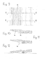
- the platform 12 is made up of a series of floor profile elements 26 which are laterally interconnected such that a desired overall width is obtained which corresponds to the size and dimensions of the loading floor of the lorry 10.
- an extractable and longitudinally sliding section bar 28 is housed in each of said floor profile elements 26 in each of said floor profile elements 26.
- the series of extractable section bars 28 is interconnected by a front crosshead 30.
- the platform according to the invention enables a single operator to easily connect the loading floor of the lorry 10 by means of said platform 12 installed within said lorry 10 with an unloading plane of different level (ground 24) or equal level.
- the platform according to the invention is made up of modular parts constituted by extruded profile elements 26 and section bars 28 of aluminium.
- the floor profile elements 26 are shaped and interconnected such that they build the new loading floor for any lorry of whatever shape and dimension and having a small or medium capacity. Thanks to its lightness, the new platform does only slightly affect the final carrying capacity of the lorry 10.
- the loading platform is made up of series of floor profile elements 26 having a closed bottom ( figure 5a ) and a height of 40 mm, which are alternately coupled to a further series of floor profile elements 26 having an open bottom ( figure 5b ), such that the overall height of the entire loading floor is of 44 mm.
- Each extractable section bar 28 (see figure 5 ) has a height of 32,5 mm and constitutes the loading and/or unloading platform for materials loaded in the lorry 10.
- the extractable section bars 28 are laterally slidable on guide shoes 32 of synthetic material which are fastened on vertical walls of said floor profile elements 26.
- the series of extractable section bars 28 is subdivided into an inclinable front series and a rear series (horizontal part 16) of section bars. Both series are interconnected by hinge joints 18 having horizontal axes.
- the front series of said extractable section bars 28 constitute, in its extracted position, the inclined platform 20.
- Figure 4 shows that a transversal ramp 36 having a wedge-shaped section is fastened to the front edge of said crosshead 30.
- each of said buffer elements 34 is made up of a ramp 86 fixed to the corresponding floor profile element 26 and of a notch 38.
- the extractable section bars 28 are provided with load distribution means 40 for uniformly distributing the weight acting on the ramp.
- Said distribution means 40 are constituted, for every second section bar 28, by a pair of svivel fingers 42 interconnected by a spring 44 and rotably mounted on a vertical axis 46 such that, in the moment of extraction, said fingers 42 will turn into their opening position and engage into seats provided in the adjacent section bar 28.
- the hinge joints 18 are provided with a lifting device 48 comprising a system of springs 50 and ropes 52 adapted to ease the weight of the ramp during the lifting phase from the inclined position into the horizontal position.
- Said lifting device 48 uses the tension of a pair of steel ropes 52 having section of 3,2 mm. Said ropes 52 are charged with a tensile stress by two pairs of preloading springs 50 which are interconnected at one end through an axis 54 fixed to the extractable section bar 28 by bolts 56. On the other end, one of said two pairs of springs 50 is connected to a rope 52 running in corresponding guides of the hinge joint 18.
- the other pair of springs 50 is connected to an axis 58 which is connected through the second rope 52 to the hinge joint 18.
- Both ropes 52 are running on four pairs of bushings 60 two of which are installed on a steel axis 62 which is fixed by means of bolts to the extractable section bar 28.
- the other two bushings are directly housed in the hinge joint 18.
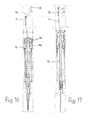
- Figures 15 to 20 illustrate that the extractable section bars 28 having the profile of an overturned U are housing a telescopic foot 64 which, in the tilting phase of the front section bars through their hinge joint 18, turn from a hidden position within the section bar 28 ( figure 19 ) into an external supporting position ( figures 18 and 20 ).
- the extension length of said telescopic feet 64 may be blocked by means of a thrust lever 66 mounted in the wedge-shaped transversal ramp 36 which is fastened to the leading edge of the front crosshead 30.
- Said crosshead 30 performs a double action, namely to connect the loading platform with the ground and to act as a telescopic setting mechanism for the feet 64 housed within the extractable section bars 28.
- said thrust lever 66 housed in said crosshead stretches a steel cable 68 which is connected to an axis on which a second lever 70 is rotably mounted. Said traction will rotate the bushing through 80°.
- the lever is housed within the floor profile element 26.
- One end of said lever 70 is connected to a spring 72 which is coupled through a steel cable 74 to a slide 76.
- said lever 70 executes its rotation, it will pull the slide 76 comprising four pulleys 78 and running on the support having two other pulleys 80.
- a cable 82 of nylon is running which triples the stroke of said cable.
Landscapes
- Engineering & Computer Science (AREA)
- Transportation (AREA)
- Mechanical Engineering (AREA)
- Auxiliary Methods And Devices For Loading And Unloading (AREA)
- Load-Engaging Elements For Cranes (AREA)
- Conveying And Assembling Of Building Elements In Situ (AREA)
- Bridges Or Land Bridges (AREA)
- Loading Or Unloading Of Vehicles (AREA)
Claims (13)
- Plattform mit Rampe an kleinen oder mittelgroßen Lastkraftwagen (10) zum Beladen oder Entladen von Material oder zum Überwinden von konstruktiven Barrieren, wobei die Plattform aus einer Anzahl von Bodenprofilelementen (26) zusammengesetzt ist, die an ihren Seiten so miteinander verbunden sind, dass eine gewünschte Gesamtbreite erzielt wird, und wobei jedes Profilelement (26) eine in Längsrichtung verstellbare, herausziehbare Profilschiene (28) aufnimmt, dadurch gekennzeichnet , dass die Gruppe der ausziehbaren Profilschienen (28), die durch einen vorderen Querriegel (30) miteinander verbunden sind, in eine vordere und eine hintere Reihe von Profilschienen unterteilt ist, die beide über Scharniere (18) mit horizontalen Schwenkachsen miteinander gekoppelt sind.
- Plattform nach Anspruch 1, dadurch gekennzeichnet, dass die vordere Reihe der ausziehbaren Profilschienen in ihrer herausgezogenen Position eine schräge Plattform (20) bildet.
- Plattform nach Anspruch 1 oder 2, dadurch gekennzeichnet, dass wenigstens ein Teil der Bodenprofilelemente (26) an ihrer unteren Seite geschlossen ist.
- Plattform nach Anspruch 3, dadurch gekennzeichnet, dass die Bodenprofilelemente (26) in der durch sie gebildeten Einheit so angeordnet sind, dass ein an der unteren Seite geschlossenes Element mit einem unten offenen Element abwechselt.
- Plattform nach einem der vorhergehenden Ansprüche, dadurch gekennzeichnet, dass die ausziehbaren Profilschienen (28) seitlich auf Führungsbacken (32) aus Kunststoff gleiten, welche an vertikalen Wänden der Bodenprofilelemente (26) befestigt sind.
- Plattform nach einem der vorhergehenden Ansprüche, dadurch gekennzeichnet, dass an dem vorderen Querriegel (30) ein keilförmiger Rampenabschnitt (36) befestigt ist.
- Plattform nach einem der vorhergehenden Ansprüche, dadurch gekennzeichnet, dass die hintere Reihe der Profilschienen (28) Anschlagelemente (34) zum Begrenzen des Verschiebeweges der Profilschienen (28) in der maximalen Auszugsstellung innerhalb des zugehörigen Bodenprofilelementes (26) haben.
- Plattform nach einem der vorhergehenden Ansprüche, dadurch gekennzeichnet, dass die ausziehbaren Profilschienen (28) Lastverteilmittel (40) haben, welche die auf die Rampe wirkenden Gewichtskräfte gleichmäßig auf diese aufteilen.
- Plattform nach Anspruch 8, dadurch gekennzeichnet, dass die Lastverteilmittel (40) in jeder zweiten Profilschiene (28) aus einem Paar von Schwenkfingern (42) bestehen, die über eine Feder (44) miteinander verbunden und um eine vertikale Achse (46) schwenkbar gelagert sind derart, dass im Augenblick des Herausziehens die Finger (42) in ihre Öffnungsstellung gelangen und in entsprechende Sitze in der benachbarten Profilschiene (28) eingreifen.
- Plattform nach einem der vorhergehenden Ansprüche, dadurch gekennzeichnet, dass die Scharniere (18) eine Hubeinrichtung (48) mit Federsystem (50) und Seilen (52) zur Gewichtsreduzierung der Rampe während des Anhebens und Absenkens aufweisen.
- Plattform nach einem der vorhergehenden Ansprüche, dadurch gekennzeichnet, dass die ausziehbare Profilschienen (28) mit dem Querschnitt eines kopfstehenden U einen Fuß (64) aufnehmen, der in der Schwenkphase der vorderen Profilschienen um ihre Scharniere (18) aus einer verborgenen Stellung innerhalb der Profilschiene (28) in eine nach außen gekehrte Stützstellung schwenkt.
- Plattform nach Anspruch 11, dadurch gekennzeichnet, dass Füße aus Teleskopfüßen (64) bestehen.
- Plattform nach Anspruch 12, dadurch gekennzeichnet, dass die Auszugslänge der Teleskopfüße (64) mittels eines Stützhebels (66) blockierbar ist, der in dem keilförmigen Rampenabschnitt (36) gelagert ist, welcher an der Vorderkante des vorderen Querriegels (30) befestigt ist.
Applications Claiming Priority (1)
| Application Number | Priority Date | Filing Date | Title |
|---|---|---|---|
| IT000016A ITPA20060016A1 (it) | 2006-04-13 | 2006-04-13 | Pianale con rampa per piccoli e medi autocarri per lo scarico e carico di materiali o per il superamento delle barriere architettoniche. |
Publications (3)
| Publication Number | Publication Date |
|---|---|
| EP1844980A2 EP1844980A2 (de) | 2007-10-17 |
| EP1844980A3 EP1844980A3 (de) | 2008-11-12 |
| EP1844980B1 true EP1844980B1 (de) | 2011-02-16 |
Family
ID=38180427
Family Applications (1)
| Application Number | Title | Priority Date | Filing Date |
|---|---|---|---|
| EP07106173A Not-in-force EP1844980B1 (de) | 2006-04-13 | 2007-04-13 | Plattform mit Rampe zum Be- und Entladen von Gegenständen |
Country Status (4)
| Country | Link |
|---|---|
| EP (1) | EP1844980B1 (de) |
| AT (1) | ATE498511T1 (de) |
| DE (1) | DE602007012480D1 (de) |
| IT (1) | ITPA20060016A1 (de) |
Families Citing this family (12)
| Publication number | Priority date | Publication date | Assignee | Title |
|---|---|---|---|---|
| US8359691B2 (en) | 2007-02-01 | 2013-01-29 | Lift-U, Division Of Hogan Mfg., Inc. | Compact folding slide-out ramp assembly |
| CA2630370A1 (en) | 2007-05-04 | 2008-11-04 | Lift-U, Division Of Hogan Mfg., Inc. | Fold out ramp |
| CA2630568C (en) | 2007-05-04 | 2010-03-16 | Lift-U, Division Of Hogan Mfg., Inc. | Counterbalance assembly for a fold out ramp |
| US7870631B2 (en) | 2008-05-02 | 2011-01-18 | Lift-U, Division Of Hogan Mfg., Inc. | Fold out ramp |
| US7913341B1 (en) | 2009-10-16 | 2011-03-29 | Lift-U, A Division Of Hogan Mfg., Inc. | Counterbalance mechanism for fold out ramp |
| US7913342B1 (en) | 2009-10-16 | 2011-03-29 | Lift-U, A Division Of Hogan Mfg., Inc. | Counterbalance mechanism for fold out ramp |
| US7913343B1 (en) | 2009-10-16 | 2011-03-29 | Lift-U, A Division Of Hogan Mfg., Inc. | Counterbalance mechanism for fold out ramp |
| US8020234B2 (en) | 2009-10-16 | 2011-09-20 | Lift-U, A Division Of Hogan Mfg., Inc. | Counterbalance mechanism for fold out ramp |
| US8250693B1 (en) | 2011-01-27 | 2012-08-28 | Lift-U, Division Of Hogan Mfg., Inc. | Fold out ramp |
| US8375496B1 (en) | 2011-01-27 | 2013-02-19 | Lift-U, Division Of Hogan Mfg., Inc. | Fold out ramp |
| US8132281B1 (en) | 2011-01-27 | 2012-03-13 | Lift-U, Division Of Hogan Mfg., Inc. | Fold out ramp |
| CN112776701A (zh) * | 2021-01-06 | 2021-05-11 | 南京傲白雪商贸有限公司 | 一种钳夹式重型罐体运输车架 |
Family Cites Families (6)
| Publication number | Priority date | Publication date | Assignee | Title |
|---|---|---|---|---|
| US4540328A (en) * | 1982-11-26 | 1985-09-10 | Mcmanama Charles E | Logging trailer |
| ES2182959T3 (es) * | 1996-12-04 | 2003-03-16 | Andrea Ciocca | Dispositivo con plataforma extraible para salvar los desniveles. |
| FR2778880B1 (fr) * | 1998-05-20 | 2000-07-21 | Lohr Ind | Structure arriere de support et de positionnement pour un vehicule de transport de voitures |
| GB9821674D0 (en) * | 1998-10-05 | 1998-12-02 | Intellitec Mv Ltd | Ramp |
| US6328366B1 (en) * | 2000-04-13 | 2001-12-11 | Meritor Heavy Vehicle Systems, Llc | Vehicle storage compartment |
| EP1405760A1 (de) * | 2002-10-04 | 2004-04-07 | Beat Maurer | Wohnmobil mit Garage |
-
2006
- 2006-04-13 IT IT000016A patent/ITPA20060016A1/it unknown
-
2007
- 2007-04-13 AT AT07106173T patent/ATE498511T1/de not_active IP Right Cessation
- 2007-04-13 DE DE602007012480T patent/DE602007012480D1/de active Active
- 2007-04-13 EP EP07106173A patent/EP1844980B1/de not_active Not-in-force
Also Published As
| Publication number | Publication date |
|---|---|
| EP1844980A2 (de) | 2007-10-17 |
| DE602007012480D1 (de) | 2011-03-31 |
| EP1844980A3 (de) | 2008-11-12 |
| ITPA20060016A1 (it) | 2007-10-14 |
| ATE498511T1 (de) | 2011-03-15 |
Similar Documents
| Publication | Publication Date | Title |
|---|---|---|
| EP1844980A2 (de) | Plattform mit Rampe zum Be- und Entladen von Gegenständen | |
| JP6133880B2 (ja) | 積み上げルーフラック | |
| US9815672B2 (en) | Loading apparatus | |
| AU2009323228B2 (en) | Dock leveler | |
| US20110202199A1 (en) | Cargo Loading and Unloading System for a Vehicle | |
| KR101764396B1 (ko) | 암롤트럭의 적재함 안전장치 | |
| US7832975B1 (en) | Spring-biased folding truck ramp | |
| US4087007A (en) | Cargo platform system | |
| CA2347561A1 (en) | Hoist for pickup truck | |
| US7635248B2 (en) | Truck bed assembly with integral partial sliding deck with pivoting inclined towers for raising and lowering a sliding deck | |
| EP2524860B1 (de) | Klappbarer Anhänger | |
| US12043212B1 (en) | Articulating cargo/ladder rack for trucks and vehicles | |
| US11312283B2 (en) | Mobile platform for a vehicle baggage compartment | |
| EP1329357B1 (de) | Kipperfahrzeug | |
| US20100061834A1 (en) | Platform for carrying and transporting loads with an unrollable floor, and transport device with a platform of this type | |
| US9463729B2 (en) | Slide and dump trailer | |
| GB2107671A (en) | Platform lift | |
| CA3183743A1 (en) | Deployable rack for loading and transportation of flat glass | |
| US6269963B1 (en) | Transport container | |
| DE102012011223A1 (de) | Ladebodenanordnung für einen Kraftwagen | |
| FR3102727A1 (fr) | Dispositif de déplacements sécurisé d’une charge portée par une palette. | |
| CA2665591C (en) | Vehicle carrier device | |
| EP2058244B1 (de) | Container | |
| EP1145900A1 (de) | Ladevorrichtung für ein Transportfahrzeug | |
| NL2008410C2 (nl) | Laadbrug voor een laadperron en werkwijze voor het laden en lossen van dubbeldekstrailers. |
Legal Events
| Date | Code | Title | Description |
|---|---|---|---|
| PUAI | Public reference made under article 153(3) epc to a published international application that has entered the european phase |
Free format text: ORIGINAL CODE: 0009012 |
|
| AK | Designated contracting states |
Kind code of ref document: A2 Designated state(s): AT BE BG CH CY CZ DE DK EE ES FI FR GB GR HU IE IS IT LI LT LU LV MC MT NL PL PT RO SE SI SK TR |
|
| AX | Request for extension of the european patent |
Extension state: AL BA HR MK YU |
|
| PUAL | Search report despatched |
Free format text: ORIGINAL CODE: 0009013 |
|
| AK | Designated contracting states |
Kind code of ref document: A3 Designated state(s): AT BE BG CH CY CZ DE DK EE ES FI FR GB GR HU IE IS IT LI LT LU LV MC MT NL PL PT RO SE SI SK TR |
|
| AX | Request for extension of the european patent |
Extension state: AL BA HR MK RS |
|
| 17P | Request for examination filed |
Effective date: 20090507 |
|
| 17Q | First examination report despatched |
Effective date: 20090618 |
|
| AKX | Designation fees paid |
Designated state(s): AT BE BG CH CY CZ DE DK EE ES FI FR GB GR HU IE IS IT LI LT LU LV MC MT NL PL PT RO SE SI SK TR |
|
| GRAP | Despatch of communication of intention to grant a patent |
Free format text: ORIGINAL CODE: EPIDOSNIGR1 |
|
| GRAS | Grant fee paid |
Free format text: ORIGINAL CODE: EPIDOSNIGR3 |
|
| GRAA | (expected) grant |
Free format text: ORIGINAL CODE: 0009210 |
|
| AK | Designated contracting states |
Kind code of ref document: B1 Designated state(s): AT BE BG CH CY CZ DE DK EE ES FI FR GB GR HU IE IS IT LI LT LU LV MC MT NL PL PT RO SE SI SK TR |
|
| REG | Reference to a national code |
Ref country code: GB Ref legal event code: FG4D |
|
| REG | Reference to a national code |
Ref country code: CH Ref legal event code: EP |
|
| REG | Reference to a national code |
Ref country code: IE Ref legal event code: FG4D |
|
| REF | Corresponds to: |
Ref document number: 602007012480 Country of ref document: DE Date of ref document: 20110331 Kind code of ref document: P |
|
| REG | Reference to a national code |
Ref country code: DE Ref legal event code: R096 Ref document number: 602007012480 Country of ref document: DE Effective date: 20110331 |
|
| REG | Reference to a national code |
Ref country code: NL Ref legal event code: VDEP Effective date: 20110216 |
|
| LTIE | Lt: invalidation of european patent or patent extension |
Effective date: 20110216 |
|
| PG25 | Lapsed in a contracting state [announced via postgrant information from national office to epo] |
Ref country code: LV Free format text: LAPSE BECAUSE OF FAILURE TO SUBMIT A TRANSLATION OF THE DESCRIPTION OR TO PAY THE FEE WITHIN THE PRESCRIBED TIME-LIMIT Effective date: 20110216 Ref country code: PT Free format text: LAPSE BECAUSE OF FAILURE TO SUBMIT A TRANSLATION OF THE DESCRIPTION OR TO PAY THE FEE WITHIN THE PRESCRIBED TIME-LIMIT Effective date: 20110616 Ref country code: GR Free format text: LAPSE BECAUSE OF FAILURE TO SUBMIT A TRANSLATION OF THE DESCRIPTION OR TO PAY THE FEE WITHIN THE PRESCRIBED TIME-LIMIT Effective date: 20110517 Ref country code: ES Free format text: LAPSE BECAUSE OF FAILURE TO SUBMIT A TRANSLATION OF THE DESCRIPTION OR TO PAY THE FEE WITHIN THE PRESCRIBED TIME-LIMIT Effective date: 20110527 Ref country code: LT Free format text: LAPSE BECAUSE OF FAILURE TO SUBMIT A TRANSLATION OF THE DESCRIPTION OR TO PAY THE FEE WITHIN THE PRESCRIBED TIME-LIMIT Effective date: 20110216 Ref country code: SE Free format text: LAPSE BECAUSE OF FAILURE TO SUBMIT A TRANSLATION OF THE DESCRIPTION OR TO PAY THE FEE WITHIN THE PRESCRIBED TIME-LIMIT Effective date: 20110216 |
|
| PG25 | Lapsed in a contracting state [announced via postgrant information from national office to epo] |
Ref country code: NL Free format text: LAPSE BECAUSE OF FAILURE TO SUBMIT A TRANSLATION OF THE DESCRIPTION OR TO PAY THE FEE WITHIN THE PRESCRIBED TIME-LIMIT Effective date: 20110216 Ref country code: BG Free format text: LAPSE BECAUSE OF FAILURE TO SUBMIT A TRANSLATION OF THE DESCRIPTION OR TO PAY THE FEE WITHIN THE PRESCRIBED TIME-LIMIT Effective date: 20110516 Ref country code: BE Free format text: LAPSE BECAUSE OF FAILURE TO SUBMIT A TRANSLATION OF THE DESCRIPTION OR TO PAY THE FEE WITHIN THE PRESCRIBED TIME-LIMIT Effective date: 20110216 Ref country code: PL Free format text: LAPSE BECAUSE OF FAILURE TO SUBMIT A TRANSLATION OF THE DESCRIPTION OR TO PAY THE FEE WITHIN THE PRESCRIBED TIME-LIMIT Effective date: 20110216 Ref country code: AT Free format text: LAPSE BECAUSE OF FAILURE TO SUBMIT A TRANSLATION OF THE DESCRIPTION OR TO PAY THE FEE WITHIN THE PRESCRIBED TIME-LIMIT Effective date: 20110216 Ref country code: FI Free format text: LAPSE BECAUSE OF FAILURE TO SUBMIT A TRANSLATION OF THE DESCRIPTION OR TO PAY THE FEE WITHIN THE PRESCRIBED TIME-LIMIT Effective date: 20110216 Ref country code: CY Free format text: LAPSE BECAUSE OF FAILURE TO SUBMIT A TRANSLATION OF THE DESCRIPTION OR TO PAY THE FEE WITHIN THE PRESCRIBED TIME-LIMIT Effective date: 20110216 Ref country code: SI Free format text: LAPSE BECAUSE OF FAILURE TO SUBMIT A TRANSLATION OF THE DESCRIPTION OR TO PAY THE FEE WITHIN THE PRESCRIBED TIME-LIMIT Effective date: 20110216 |
|
| PG25 | Lapsed in a contracting state [announced via postgrant information from national office to epo] |
Ref country code: DK Free format text: LAPSE BECAUSE OF FAILURE TO SUBMIT A TRANSLATION OF THE DESCRIPTION OR TO PAY THE FEE WITHIN THE PRESCRIBED TIME-LIMIT Effective date: 20110216 Ref country code: EE Free format text: LAPSE BECAUSE OF FAILURE TO SUBMIT A TRANSLATION OF THE DESCRIPTION OR TO PAY THE FEE WITHIN THE PRESCRIBED TIME-LIMIT Effective date: 20110216 |
|
| PG25 | Lapsed in a contracting state [announced via postgrant information from national office to epo] |
Ref country code: RO Free format text: LAPSE BECAUSE OF FAILURE TO SUBMIT A TRANSLATION OF THE DESCRIPTION OR TO PAY THE FEE WITHIN THE PRESCRIBED TIME-LIMIT Effective date: 20110216 Ref country code: SK Free format text: LAPSE BECAUSE OF FAILURE TO SUBMIT A TRANSLATION OF THE DESCRIPTION OR TO PAY THE FEE WITHIN THE PRESCRIBED TIME-LIMIT Effective date: 20110216 Ref country code: MC Free format text: LAPSE BECAUSE OF NON-PAYMENT OF DUE FEES Effective date: 20110430 Ref country code: CZ Free format text: LAPSE BECAUSE OF FAILURE TO SUBMIT A TRANSLATION OF THE DESCRIPTION OR TO PAY THE FEE WITHIN THE PRESCRIBED TIME-LIMIT Effective date: 20110216 |
|
| REG | Reference to a national code |
Ref country code: CH Ref legal event code: PL |
|
| PLBE | No opposition filed within time limit |
Free format text: ORIGINAL CODE: 0009261 |
|
| STAA | Information on the status of an ep patent application or granted ep patent |
Free format text: STATUS: NO OPPOSITION FILED WITHIN TIME LIMIT |
|
| PG25 | Lapsed in a contracting state [announced via postgrant information from national office to epo] |
Ref country code: MT Free format text: LAPSE BECAUSE OF FAILURE TO SUBMIT A TRANSLATION OF THE DESCRIPTION OR TO PAY THE FEE WITHIN THE PRESCRIBED TIME-LIMIT Effective date: 20110216 |
|
| REG | Reference to a national code |
Ref country code: FR Ref legal event code: ST Effective date: 20111230 |
|
| 26N | No opposition filed |
Effective date: 20111117 |
|
| GBPC | Gb: european patent ceased through non-payment of renewal fee |
Effective date: 20110516 |
|
| PG25 | Lapsed in a contracting state [announced via postgrant information from national office to epo] |
Ref country code: CH Free format text: LAPSE BECAUSE OF NON-PAYMENT OF DUE FEES Effective date: 20110430 Ref country code: FR Free format text: LAPSE BECAUSE OF NON-PAYMENT OF DUE FEES Effective date: 20110502 Ref country code: LI Free format text: LAPSE BECAUSE OF NON-PAYMENT OF DUE FEES Effective date: 20110430 Ref country code: DE Free format text: LAPSE BECAUSE OF NON-PAYMENT OF DUE FEES Effective date: 20111101 |
|
| REG | Reference to a national code |
Ref country code: IE Ref legal event code: MM4A |
|
| REG | Reference to a national code |
Ref country code: DE Ref legal event code: R119 Ref document number: 602007012480 Country of ref document: DE Effective date: 20111101 |
|
| PG25 | Lapsed in a contracting state [announced via postgrant information from national office to epo] |
Ref country code: IE Free format text: LAPSE BECAUSE OF NON-PAYMENT OF DUE FEES Effective date: 20110413 |
|
| PG25 | Lapsed in a contracting state [announced via postgrant information from national office to epo] |
Ref country code: IT Free format text: LAPSE BECAUSE OF FAILURE TO SUBMIT A TRANSLATION OF THE DESCRIPTION OR TO PAY THE FEE WITHIN THE PRESCRIBED TIME-LIMIT Effective date: 20110216 |
|
| PG25 | Lapsed in a contracting state [announced via postgrant information from national office to epo] |
Ref country code: GB Free format text: LAPSE BECAUSE OF NON-PAYMENT OF DUE FEES Effective date: 20110516 |
|
| PG25 | Lapsed in a contracting state [announced via postgrant information from national office to epo] |
Ref country code: LU Free format text: LAPSE BECAUSE OF NON-PAYMENT OF DUE FEES Effective date: 20110413 |
|
| PG25 | Lapsed in a contracting state [announced via postgrant information from national office to epo] |
Ref country code: IS Free format text: LAPSE BECAUSE OF FAILURE TO SUBMIT A TRANSLATION OF THE DESCRIPTION OR TO PAY THE FEE WITHIN THE PRESCRIBED TIME-LIMIT Effective date: 20110216 |
|
| PG25 | Lapsed in a contracting state [announced via postgrant information from national office to epo] |
Ref country code: TR Free format text: LAPSE BECAUSE OF FAILURE TO SUBMIT A TRANSLATION OF THE DESCRIPTION OR TO PAY THE FEE WITHIN THE PRESCRIBED TIME-LIMIT Effective date: 20110216 |
|
| PG25 | Lapsed in a contracting state [announced via postgrant information from national office to epo] |
Ref country code: HU Free format text: LAPSE BECAUSE OF FAILURE TO SUBMIT A TRANSLATION OF THE DESCRIPTION OR TO PAY THE FEE WITHIN THE PRESCRIBED TIME-LIMIT Effective date: 20110216 |