EP1844960A1 - Machine for assembling and disassembling a tyre fitted with a rigid inner run-flat ring - Google Patents
Machine for assembling and disassembling a tyre fitted with a rigid inner run-flat ring Download PDFInfo
- Publication number
- EP1844960A1 EP1844960A1 EP07106201A EP07106201A EP1844960A1 EP 1844960 A1 EP1844960 A1 EP 1844960A1 EP 07106201 A EP07106201 A EP 07106201A EP 07106201 A EP07106201 A EP 07106201A EP 1844960 A1 EP1844960 A1 EP 1844960A1
- Authority
- EP
- European Patent Office
- Prior art keywords
- axis
- tool
- tyre
- slide
- machine
- Prior art date
- Legal status (The legal status is an assumption and is not a legal conclusion. Google has not performed a legal analysis and makes no representation as to the accuracy of the status listed.)
- Granted
Links
- 239000011324 bead Substances 0.000 description 18
- 238000003780 insertion Methods 0.000 description 3
- 230000037431 insertion Effects 0.000 description 3
- 238000000605 extraction Methods 0.000 description 2
- 239000013536 elastomeric material Substances 0.000 description 1
- 239000002184 metal Substances 0.000 description 1
- 230000000284 resting effect Effects 0.000 description 1
Images




Classifications
-
- B—PERFORMING OPERATIONS; TRANSPORTING
- B60—VEHICLES IN GENERAL
- B60C—VEHICLE TYRES; TYRE INFLATION; TYRE CHANGING; CONNECTING VALVES TO INFLATABLE ELASTIC BODIES IN GENERAL; DEVICES OR ARRANGEMENTS RELATED TO TYRES
- B60C25/00—Apparatus or tools adapted for mounting, removing or inspecting tyres
- B60C25/01—Apparatus or tools adapted for mounting, removing or inspecting tyres for removing tyres from or mounting tyres on wheels
- B60C25/05—Machines
- B60C25/132—Machines for removing and mounting tyres
- B60C25/135—Machines for removing and mounting tyres having a tyre support or a tool, movable along wheel axis
- B60C25/138—Machines for removing and mounting tyres having a tyre support or a tool, movable along wheel axis with rotary motion of tool or tyre support
-
- B—PERFORMING OPERATIONS; TRANSPORTING
- B60—VEHICLES IN GENERAL
- B60C—VEHICLE TYRES; TYRE INFLATION; TYRE CHANGING; CONNECTING VALVES TO INFLATABLE ELASTIC BODIES IN GENERAL; DEVICES OR ARRANGEMENTS RELATED TO TYRES
- B60C25/00—Apparatus or tools adapted for mounting, removing or inspecting tyres
- B60C25/01—Apparatus or tools adapted for mounting, removing or inspecting tyres for removing tyres from or mounting tyres on wheels
- B60C25/05—Machines
- B60C25/0509—Machines for inserting additional parts, e.g. support rings, sensors
Definitions
- the present invention relates to a machine for assembling and disassembling a tyre fitted with a rigid inner run-flat ring.
- tyres of the above type are normally assembled and disassembled using special, relatively complex, high-cost powered devices completely separate from the tyre removing machines used to assemble and remove the tyre to and from the rim.
- a machine for assembling and disassembling a tyre fitted with a rigid inner run-flat ring as claimed in the accompanying independent Claims and, preferably, in any one of the Claims depending directly or indirectly on the independent Claims.
- Number 1 in Figure 2 indicates as a whole a machine - actually a conventional tyre removing machine - equipped with accessories for assembling and disassembling a conventional tyre 2 fitted with a known rigid inner run-flat ring 3.
- tyre 2 comprises two beads 4 and 5 defining the ends of a toroidal chamber 6.
- Rigid ring 3 is housed inside toroidal chamber 6, and comprises an undulated toroidal metal central portion 7, the maximum outside diameter of which is larger than the inside diameter of beads 4 and 5 and slightly larger than the maximum diameter of toroidal chamber 6 minus the maximum radial depth of toroidal chamber 6; and two beads 8 and 9 made of elastomeric material and of substantially the same inside diameter as beads 4 and 5.
- tyre removing machine 1 comprises a powered turntable 10 having a vertical axis 11 and, on top, a height-adjustable plate 12, which rotates about axis 11, supports a tub-shaped tool 13 with its concavity facing upwards, and has a known locating device 14 for engaging a bottom flange 15 of tub-shaped tool 13 to lock tub-shaped tool 13 radially in a position coaxial with axis 11 when tub-shaped tool 13 is placed on plate 12 with bottom flange 15 facing downwards.
- Tyre removing machine 1 also comprises a tool column 16 located alongside turntable 10 and in turn comprising a base 17, from which extends upwards a vertical prismatic guide 18 for a slide 19 moved along prismatic guide 18 by a single hydraulic or pneumatic jack 20 interposed between slide 19 and base 17.
- Slide 19 is fitted with a number of tools - not shown for the sake of simplicity - for assembling and disassembling a wheel (not shown) comprising tyre 2, relative rigid ring 3, and a relative rim (not shown).
- tub-shaped tool 13 a tube 21 extends through bottom flange 15, is maintained, in use, coaxial with axis 11 by locating device 14, and is fitted with the facing ends of two coaxial, diametrically opposite sleeves 22 and 23 engaged by specular tubular members 24 and 25 respectively.
- Tubular members 24 and 25 are L-shaped, lie in a diametrical plane of axis 11 to define two supporting ribs of tub-shaped tool 13, and comprise respective bottom arms 26 perpendicular to axis 11 and coaxial with each other and with sleeves 22, 23; and respective top arms 27 parallel to each other and to axis 11, and located in said diametrical plane, on opposite sides of axis 11.
- bottom arm 26 of tubular member 24 is integral with sleeve 22, whereas bottom arm 26 of tubular member 25 engages sleeve 23 in sliding manner, and can be fixed selectively in any of a number of given axial positions with respect to sleeve 23, by means of a diametrical pin 28.
- top arms 27 support an annular rib 29 coaxial with axis 11 and lying in a plane perpendicular to axis 11.
- Annular rib 29 comprises a fixed portion 30, which is integral with tubular member 24, extends roughly 320° about axis 11, and is connected to bottom flange 15 by curved radial arms 31, and to sleeve 22 by a scoop 32; and a movable portion 33 movable radially with tubular member 25 and connected to a top end of a scoop 34, which is specular with respect to scoop 32 and has a bottom end resting on sleeve 23.
- a sleeve 36 is fixed, in an axially adjustable position, to top arm 27 of tubular member 24 by a removable radial pin 35, and is fitted with an annular segment-shaped plate 37 projecting, with respect to relative top arm 27, towards tubular member 25.
- a sleeve 39 is fixed, in an axially and angularly adjustable position, to top arm 27 of tubular member 25 by a removable radial pin 38, and is fitted with an annular segment-shaped plate 40 projecting, with respect to relative top arm 27, towards tubular member 24.
- Plates 37 and 40 are adjusted so as to be coplanar with a plane perpendicular to axis 11, and, whereas plate 37 is always oriented towards axis 11 with respect to relative top arm 27, plate 40 is adjustable about relative top arm 27 to selectively assume a first position (Figure 3) facing tubular member 24, and a second position facing outwards of tub-shaped tool 13, a concave bottom surface 41 of which is defined by scoops 32 and 34, by radial arms 31, and by two curved ribs 42 located on opposite sides of the diametrical plane - coincident with the Figure 2 plane - defined by tubular members 24, 25 and extending upwards from bottom flange 15.
- slide 19 has a horizontal prismatic through guide (not shown) lying in said diametrical plane and engaged in sliding manner by a rod 43, which forms part of a removable accessory 44, can be fixed in any axial position to slide 19, and has an end portion projecting from slide 19 towards turntable 10.
- Accessory 44 also comprises an L-shaped bracket 45, one end of which is fitted with a transverse sleeve 46 fitted to the portion of rod 43 projecting from slide 19, and the other end of which is fitted with another transverse sleeve 47, which has an axis parallel to axis 11, lies in said diametrical plane, and is located over plate 12, on the same side of axis 11 as tool column 16.
- Accessory 44 also comprises a pressure tool 48, also located in said diametrical plane and in turn comprising a rod 49 fitted in an axially adjustable position through sleeve 47 and terminating, at the end facing plate 12, with a pad 50; and an appendix 51, also located in said diametrical plane, and which slopes downwards towards axis 11 from a portion of rod 49 just above pad 50, and terminates, at the end facing plate 12, with a pad 52 located on the opposite side of axis 11 to pad 50, and separated from pad 50 by a distance, measured crosswise to axis 11, greater than the distance between beads 8 and 9.
- a pressure tool 48 also located in said diametrical plane and in turn comprising a rod 49 fitted in an axially adjustable position through sleeve 47 and terminating, at the end facing plate 12, with a pad 50
- an appendix 51 also located in said diametrical plane, and which slopes downwards towards axis 11 from a portion of rod 49 just above pad 50, and terminate
- tub-shaped tool 13 is fixed to plate 12 with its concavity facing upwards, and with its own axis 53 ( Figure 2) coincident with axis 11; the height of sleeves 36 and 39 and the radial position of tubular member 25 are adjusted according to the size of tyre 2; plate 40 is locked angularly in the inner position, i.e. facing plate 37; and tyre 2 is placed flat on the support defined by plates 37 and 40, with its bead 5 facing downwards, and with its own axis 54 (Figure 2) substantially coaxial with axis 11.
- rigid ring 3 whose outside diameter is only slightly greater than the inside diameter of beads 4 and 5, and whose thickness is less than the height of toroidal chamber 6, is placed on-edge on tyre 2, with central portion 7 contacting bead 4, and so that an equatorial plane 55 (Figure 2) of rigid ring 3 contains axis 11, and an axis 56 ( Figure 2) of rigid ring 3 is parallel to rod 43.
- rod 43 is moved forward to insert appendix 51 inside rigid ring 3; and rod 49 is lowered, with respect to sleeve 47, to lower pad 52 onto the inner periphery of bead 8, and is then locked axially to sleeve 47.
- Jack 20 is then operated to move slide 19 down prismatic guide 18 and so insert rigid ring 3 on-edge inside tyre 2, by pressure tool 48 exerting thrust on rigid ring 3, and simultaneously deform beads 4 and 5.
- This insertion stage is completed ( Figure 4) when axis 56 of rigid ring 3 lies on an equatorial plane 57 of the tyre.
- appendix 51 is extracted from rigid ring 3 by rotating rod 49 inside sleeve 47 and raising slide 19; plate 40 is locked angularly in the outer position (Figure 5); and the tyre 2-rigid ring 3 assembly is placed on bottom surface 41 of tub-shaped tool 13, with tyre 2 tilted and laterally contacting scoop 32, and with rigid ring 3 tilted, laterally contacting ribs 42, and with its highest point positioned directly beneath pad 50.
- pad 50 acts on rigid ring 3 to rotate tyre 2 and rigid ring 3 in opposite directions (Figure 5) on bottom surface 41 and about an instantaneous axis 58 perpendicular to the Figure 5 plane and substantially coincident with the intersection of equatorial planes 55 and 57, and so insert rigid ring 3 completely inside toroidal chamber 6 ( Figure 6).
- tyre 2 fitted completely with rigid ring 3, is laid flat inside, and can be extracted from, tub-shaped tool 13.
- tub-shaped tool 13 is fixed to plate 12 with its concavity facing upwards, and with its own axis 53 ( Figure 3) coincident with axis 11; the height of sleeves 36 and 39 and the radial position of tubular member 25 are adjusted according to the size of tyre 2; plate 40 is locked angularly in the inner position, i.e.
- tyre 2 is placed flat on the support defined by plates 37 and 40, with its bead 5 facing downwards, and with its own axis 54 ( Figure 1) substantially coaxial with axis 11; and rigid ring 3 is moved laterally, inside toroidal chamber 6, away from tool column 16, so that a portion of bead 8 is positioned radially inwards of the relative portion of bead 4 and directly accessible by pad 50.
- rod 43 is moved forward to position pad 50 directly over said portion of bead 8; and rod 49 is lowered, with respect to sleeve 47, to lower pad 50 ( Figure 7) onto said portion of bead 8, and is then locked axially to sleeve 47.
- Jack 20 is then operated to move slide 19 down prismatic guide 18 (Figure 8) and produce a simultaneous rotation-translation movement of rigid ring 3 about an instantaneous axis 59 perpendicular to the Figure 8 plane and substantially lying in equatorial plane 55, so that part of rigid ring 3 is extracted downwards from toroidal chamber 6.
- the above rotation continues, by pressure tool 48 exerting thrust on rigid ring 3, until rigid ring 3 is positioned substantially on edge with respect to tyre 2 ( Figure 9).
- pad 50 is detached from bead 8 by raising slide 19 until pad 52 is positioned higher than the bottom portion of bead 9; rigid ring 3 is then manually rotated further by the operator to position central portion 7 of rigid ring 3 directly beneath pad 52; and slide 19 is lowered ( Figure 9) to bring pad 52 into direct contact with the inner surface of central portion 7 of rigid ring 3.
- tyre removing machine 1 As compared with known assembly and disassembly devices, are obvious, considering that, on tyre removing machine 1, rigid ring 3 is inserted and extracted using a power member - in this case, jack 20 - already provided on tyre removing machine 1 for other purposes, and by simply equipping tyre removing machine 1 with relatively low-cost, low-tech, compact, lightweight accessory tools - in this case, tub-shaped tool 13 and pressure tool 48.
Landscapes
- Engineering & Computer Science (AREA)
- Mechanical Engineering (AREA)
- Tires In General (AREA)
Abstract
Description
- The present invention relates to a machine for assembling and disassembling a tyre fitted with a rigid inner run-flat ring.
- In the tyre business, tyres of the above type are normally assembled and disassembled using special, relatively complex, high-cost powered devices completely separate from the tyre removing machines used to assemble and remove the tyre to and from the rim.
- It is an object of the present invention to eliminate the need for said special devices.
- According to the present invention, there is provided a machine for assembling and disassembling a tyre fitted with a rigid inner run-flat ring, as claimed in the accompanying independent Claims and, preferably, in any one of the Claims depending directly or indirectly on the independent Claims.
- A non-limiting embodiment of the present invention will be described by way of example with reference to the accompanying drawings, in which:
- Figure 1 shows an axial section of a tyre fitted with a rigid inner run-flat ring;
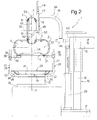
- Figure 2 shows a schematic side view, with parts in section and parts removed for clarity, of a preferred embodiment of the machine according to the present invention;
- Figure 3 shows a larger-scale view in perspective of a detail in Figure 2;
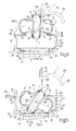
- Figures 4 to 6 show partial, larger-scale, partly sectioned views of a first operating sequence of the Figure 2 machine;
- Figures 7 to 10 show partial, larger-scale, partly sectioned views of a second operating sequence of the Figure 2 machine.
-
Number 1 in Figure 2 indicates as a whole a machine - actually a conventional tyre removing machine - equipped with accessories for assembling and disassembling aconventional tyre 2 fitted with a known rigid inner run-flat ring 3. - As shown more clearly in Figure 1,
tyre 2 comprises twobeads toroidal chamber 6.Rigid ring 3 is housed insidetoroidal chamber 6, and comprises an undulated toroidal metalcentral portion 7, the maximum outside diameter of which is larger than the inside diameter ofbeads toroidal chamber 6 minus the maximum radial depth oftoroidal chamber 6; and twobeads beads - As shown more clearly in Figure 2,
tyre removing machine 1 comprises a poweredturntable 10 having avertical axis 11 and, on top, a height-adjustable plate 12, which rotates aboutaxis 11, supports a tub-shaped tool 13 with its concavity facing upwards, and has a known locatingdevice 14 for engaging abottom flange 15 of tub-shaped tool 13 to lock tub-shaped tool 13 radially in a position coaxial withaxis 11 when tub-shaped tool 13 is placed onplate 12 withbottom flange 15 facing downwards. -
Tyre removing machine 1 also comprises atool column 16 located alongsideturntable 10 and in turn comprising abase 17, from which extends upwards a verticalprismatic guide 18 for aslide 19 moved alongprismatic guide 18 by a single hydraulic orpneumatic jack 20 interposed betweenslide 19 andbase 17. -
Slide 19 is fitted with a number of tools - not shown for the sake of simplicity - for assembling and disassembling a wheel (not shown) comprisingtyre 2, relativerigid ring 3, and a relative rim (not shown). - As shown more clearly in Figure 3, in tub-
shaped tool 13, atube 21 extends throughbottom flange 15, is maintained, in use, coaxial withaxis 11 by locatingdevice 14, and is fitted with the facing ends of two coaxial, diametricallyopposite sleeves tubular members Tubular members axis 11 to define two supporting ribs of tub-shaped tool 13, and compriserespective bottom arms 26 perpendicular toaxis 11 and coaxial with each other and withsleeves top arms 27 parallel to each other and toaxis 11, and located in said diametrical plane, on opposite sides ofaxis 11. More specifically,bottom arm 26 oftubular member 24 is integral withsleeve 22, whereasbottom arm 26 oftubular member 25 engagessleeve 23 in sliding manner, and can be fixed selectively in any of a number of given axial positions with respect tosleeve 23, by means of a diametrical pin 28. Close to their respective bases,top arms 27 support anannular rib 29 coaxial withaxis 11 and lying in a plane perpendicular toaxis 11.Annular rib 29 comprises a fixedportion 30, which is integral withtubular member 24, extends roughly 320° aboutaxis 11, and is connected tobottom flange 15 by curvedradial arms 31, and to sleeve 22 by ascoop 32; and amovable portion 33 movable radially withtubular member 25 and connected to a top end of ascoop 34, which is specular with respect toscoop 32 and has a bottom end resting onsleeve 23. - A
sleeve 36 is fixed, in an axially adjustable position, totop arm 27 oftubular member 24 by a removableradial pin 35, and is fitted with an annular segment-shaped plate 37 projecting, with respect to relativetop arm 27, towardstubular member 25. Similarly, asleeve 39 is fixed, in an axially and angularly adjustable position, totop arm 27 oftubular member 25 by a removableradial pin 38, and is fitted with an annular segment-shaped plate 40 projecting, with respect to relativetop arm 27, towardstubular member 24.Plates axis 11, and, whereasplate 37 is always oriented towardsaxis 11 with respect to relativetop arm 27,plate 40 is adjustable about relativetop arm 27 to selectively assume a first position (Figure 3) facingtubular member 24, and a second position facing outwards of tub-shaped tool 13, aconcave bottom surface 41 of which is defined byscoops radial arms 31, and by twocurved ribs 42 located on opposite sides of the diametrical plane - coincident with the Figure 2 plane - defined bytubular members bottom flange 15. - As shown in Figure 2,
slide 19 has a horizontal prismatic through guide (not shown) lying in said diametrical plane and engaged in sliding manner by arod 43, which forms part of aremovable accessory 44, can be fixed in any axial position to slide 19, and has an end portion projecting fromslide 19 towardsturntable 10.Accessory 44 also comprises an L-shaped bracket 45, one end of which is fitted with atransverse sleeve 46 fitted to the portion ofrod 43 projecting fromslide 19, and the other end of which is fitted with anothertransverse sleeve 47, which has an axis parallel toaxis 11, lies in said diametrical plane, and is located overplate 12, on the same side ofaxis 11 astool column 16.Accessory 44 also comprises apressure tool 48, also located in said diametrical plane and in turn comprising arod 49 fitted in an axially adjustable position throughsleeve 47 and terminating, at theend facing plate 12, with apad 50; and anappendix 51, also located in said diametrical plane, and which slopes downwards towardsaxis 11 from a portion ofrod 49 just abovepad 50, and terminates, at theend facing plate 12, with apad 52 located on the opposite side ofaxis 11 topad 50, and separated frompad 50 by a distance, measured crosswise toaxis 11, greater than the distance betweenbeads - Below are described an insertion sequence (Figures 2 and 4-6) to insert
rigid ring 3 insidetoroidal chamber 6, and an extraction sequence (Figures 7-10) to extractrigid ring 3 fromtoroidal chamber 6. - Before commencing the insertion sequence (Figure 2),
slide 19 is moved into the topmost position; tub-shaped tool 13 is fixed toplate 12 with its concavity facing upwards, and with its own axis 53 (Figure 2) coincident withaxis 11; the height ofsleeves tubular member 25 are adjusted according to the size oftyre 2;plate 40 is locked angularly in the inner position, i.e. facingplate 37; andtyre 2 is placed flat on the support defined byplates bead 5 facing downwards, and with its own axis 54 (Figure 2) substantially coaxial withaxis 11. At this point,rigid ring 3, whose outside diameter is only slightly greater than the inside diameter ofbeads toroidal chamber 6, is placed on-edge ontyre 2, withcentral portion 7 contactingbead 4, and so that an equatorial plane 55 (Figure 2) ofrigid ring 3 containsaxis 11, and an axis 56 (Figure 2) ofrigid ring 3 is parallel torod 43. - Next,
rod 43 is moved forward to insertappendix 51 insiderigid ring 3; androd 49 is lowered, with respect tosleeve 47, tolower pad 52 onto the inner periphery ofbead 8, and is then locked axially to sleeve 47. - Jack 20 is then operated to move
slide 19 downprismatic guide 18 and so insertrigid ring 3 on-edge insidetyre 2, bypressure tool 48 exerting thrust onrigid ring 3, and simultaneously deformbeads axis 56 ofrigid ring 3 lies on anequatorial plane 57 of the tyre. - At this point,
appendix 51 is extracted fromrigid ring 3 by rotatingrod 49 insidesleeve 47 and raisingslide 19;plate 40 is locked angularly in the outer position (Figure 5); and the tyre 2-rigid ring 3 assembly is placed onbottom surface 41 of tub-shaped tool 13, withtyre 2 tilted and laterally contactingscoop 32, and withrigid ring 3 tilted, laterally contactingribs 42, and with its highest point positioned directly beneathpad 50. Whenslide 19 is next lowered,pad 50 acts onrigid ring 3 to rotatetyre 2 andrigid ring 3 in opposite directions (Figure 5) onbottom surface 41 and about aninstantaneous axis 58 perpendicular to the Figure 5 plane and substantially coincident with the intersection ofequatorial planes rigid ring 3 completely inside toroidal chamber 6 (Figure 6). At this point,tyre 2, fitted completely withrigid ring 3, is laid flat inside, and can be extracted from, tub-shaped tool 13. - Before commencing the extraction sequence (Figure 7),
slide 19 is moved into the topmost position; tub-shaped tool 13 is fixed toplate 12 with its concavity facing upwards, and with its own axis 53 (Figure 3) coincident withaxis 11; the height ofsleeves tubular member 25 are adjusted according to the size oftyre 2;plate 40 is locked angularly in the inner position, i.e. facingplate 37;tyre 2 is placed flat on the support defined byplates bead 5 facing downwards, and with its own axis 54 (Figure 1) substantially coaxial withaxis 11; andrigid ring 3 is moved laterally, insidetoroidal chamber 6, away fromtool column 16, so that a portion ofbead 8 is positioned radially inwards of the relative portion ofbead 4 and directly accessible bypad 50. - Next,
rod 43 is moved forward toposition pad 50 directly over said portion ofbead 8; androd 49 is lowered, with respect tosleeve 47, to lower pad 50 (Figure 7) onto said portion ofbead 8, and is then locked axially tosleeve 47. - Jack 20 is then operated to move
slide 19 down prismatic guide 18 (Figure 8) and produce a simultaneous rotation-translation movement ofrigid ring 3 about aninstantaneous axis 59 perpendicular to the Figure 8 plane and substantially lying inequatorial plane 55, so that part ofrigid ring 3 is extracted downwards fromtoroidal chamber 6. The above rotation continues, bypressure tool 48 exerting thrust onrigid ring 3, untilrigid ring 3 is positioned substantially on edge with respect to tyre 2 (Figure 9). - At this point,
pad 50 is detached frombead 8 by raisingslide 19 untilpad 52 is positioned higher than the bottom portion ofbead 9;rigid ring 3 is then manually rotated further by the operator to positioncentral portion 7 ofrigid ring 3 directly beneathpad 52; andslide 19 is lowered (Figure 9) to bringpad 52 into direct contact with the inner surface ofcentral portion 7 ofrigid ring 3. - When
slide 19 is lowered further alongprismatic guide 18,beads rigid ring 3 is extracted (Figure 10) on-edge fromtyre 2, bypressure tool 48 exerting thrust oncentral portion 7 ofrigid ring 3; andrigid ring 3 drops ontobottom surface 41 of tub-shaped tool 13. - The advantages of
tyre removing machine 1, as compared with known assembly and disassembly devices, are obvious, considering that, ontyre removing machine 1,rigid ring 3 is inserted and extracted using a power member - in this case, jack 20 - already provided ontyre removing machine 1 for other purposes, and by simply equippingtyre removing machine 1 with relatively low-cost, low-tech, compact, lightweight accessory tools - in this case, tub-shaped tool 13 andpressure tool 48.
Claims (23)
- A machine for assembling and disassembling a tyre (2) fitted with a rigid inner run-flat ring (3) located inside a toroidal chamber (6) of the tyre (2); the machine (1) being a tyre removing machine comprising a turntable (10) having an axis (11); a tool column (16) located alongside the turntable (10) and having a guide (18) parallel to said axis (11); a slide (19) mounted to run along the guide (18); actuating means (20) for moving the slide (19) along the guide (18); and tooling comprising a first tool (13), fitted to the turntable (10) to support the tyre (2) and the rigid ring (3), and a second tool (48) fitted to the slide (19) and movable with the slide (19) along the tool column (16) to engage the rigid ring (3) and move the rigid ring (3) with respect to the tyre (2).
- A machine as claimed in Claim 1, wherein the first and second tool (13, 48) are fitted removably to the turntable (10) and the slide (19) respectively.
- A machine as claimed in Claim 1 or 2, wherein the first tool (13) is a tub-shaped tool positioned on the turntable (10) coaxially with said axis (11) and with its concavity facing upwards; the first tool (13) receiving the tyre (2) laid flat.
- A machine as claimed in one of the foregoing Claims, wherein the first tool (13) comprises first (41) and second (37, 40) supporting means for supporting the tyre (2), laid flat, in respective distinct positions along said axis (11); the second supporting means (37, 40) being located above the first supporting means (41) along said axis (11).
- A machine as claimed in Claim 4, wherein the second supporting means (37, 40) are substantially annular, and comprise a first (37) and a second (40) curved plate coplanar with each other, crosswise to said axis (11), and diametrically opposite with respect to said axis (11).
- A machine as claimed in Claim 5, wherein said first and said second plate (37, 40) are adjustable in height with respect to the first supporting means (41).
- A machine as claimed in Claim 5 or 6, wherein said second plate (40) is movable between an inner position, in which the second plate (40) is located over the first supporting means (41), and an outer position, in which the second plate (40) is moved aside with respect to the first supporting means (41), to permit access by the tyre (2) to the first supporting means (41).
- A machine as claimed in Claim 3 or one of Claims 4 to 7, wherein the first supporting means (41) are defined by a bottom of the first tool (13).
- A machine as claimed in one of the foregoing Claims, wherein the second tool (48) lies in a plane through said axis (11) .
- A machine as claimed in one of the foregoing Claims, wherein the second tool (48) is a pressure tool comprising a first (50) and a second (52) pad, which are movable with the slide (19) along said axis (11), and selectively engage the rigid ring (3) to cause the rigid ring (3) to translate along said axis (11) with respect to the tyre (2), and to rotate with respect to the tyre (2) about a further axis crosswise to said axis (11).
- A machine as claimed in Claim 10, wherein the first and second pad (50, 52) are located on opposite sides of said axis (11), and are offset in height, with the first pad (50) located above the second pad (52).
- A machine as claimed in Claim 10 or 11, wherein the second tool (48) comprises a rod (49) parallel to said axis (11) and connected in an axially adjustable position to the slide (19); the rod (49) having an inclined lateral appendix (51) extending through said axis (11) and towards the turntable (10); the first pad (50) being carried by the rod (49), and the second pad (52) being carried by the appendix (51).
- Tooling attachable to a tyre removing machine (1) to assemble and disassemble, on the tyre removing machine (1), a tyre (2) fitted with a rigid inner run-flat ring (3) located inside a toroidal chamber (6) of the tyre (2); the tyre removing machine (1) being of the type comprising a turntable (10) having an axis (11); a tool column (16) located alongside the turntable (10) and having a guide (18) parallel to said axis (11); a slide (19) mounted to run along the guide (18); and actuating means (20) for moving the slide (19) along the guide (18); and the tooling being characterized by comprising a first tool (13) which fits onto the turntable (10) to support the tyre (2) and the rigid ring (3); and a second tool (48) which fits onto the slide (19), and is movable with the slide (19) along the tool column (16) to engage the rigid ring (3) and move the rigid ring (3) with respect to the tyre (2).
- Tooling as claimed in Claim 13, wherein the first tool (13) is a tub-shaped tool which fits onto the turntable (10) coaxially with said axis (11) and with its concavity facing upwards; the first tool (13) receiving the tyre (2) laid flat.
- Tooling as claimed in Claim 13 or 14, wherein the first tool (13) comprises first (41) and second (37, 40) supporting means for supporting the tyre (2), laid flat, in respective distinct positions; the second supporting means (37, 40) being located above the first supporting means (41) along said axis (11).
- Tooling as claimed in Claim 15, wherein the second supporting means (37, 40) are substantially annular, and comprise a first (37) and a second (40) curved plate coplanar with each other, and which are positioned, in use, crosswise to said axis (11) and diametrically opposite with respect to said axis (11).
- Tooling as claimed in Claim 16, wherein said first and said second plate (37, 40) are adjustable in height with respect to the first supporting means (41).
- Tooling as claimed in Claim 16 or 17, wherein said second plate (40) is movable between an inner position, in which the second plate (40) is located over the first supporting means (41), and an outer position, in which the second plate (40) is moved aside with respect to the first supporting means (41), to permit access by the tyre (2) to the first supporting means (41).
- Tooling as claimed in Claim 14 or one of Claims 15 to 18, wherein the first supporting means (41) are defined by a bottom of the first tool (13).
- Tooling as claimed in one of Claims 13 to 19, wherein the second tool (48) lies, in use, in a plane through said axis (11).
- Tooling as claimed in one of the foregoing Claims, wherein the second tool (48) is a pressure tool comprising a first and a second pad (50, 52), which are attachable to the slide (19) to move with the slide (19) along said axis (11), and to selectively engage the rigid ring (3) to cause the rigid ring (3) to translate along said axis (11) with respect to the tyre (2), and to rotate with respect to the tyre (2) about a further axis crosswise to said axis (11).
- Tooling as claimed in Claim 21, wherein the first and second pad (50, 52), when attached to the slide (19), are located on opposite sides of said axis (11), and are offset in height, with the first pad (50) located above the second pad (52).
- Tooling as claimed in Claim 21 or 22, wherein the second tool (48) comprises a rod (49) that can be positioned parallel to said axis (11) and is connectable in an axially adjustable position to the slide (19); the rod (49) having an inclined lateral appendix (51) extending, in use, through said axis (11) and towards the turntable (10); the first pad (50) being carried by the rod (49), and the second pad (52) being carried by the appendix (51).
Applications Claiming Priority (1)
| Application Number | Priority Date | Filing Date | Title |
|---|---|---|---|
| IT000285A ITTO20060285A1 (en) | 2006-04-14 | 2006-04-14 | MACHINE FOR ASSEMBLY AND DISASSEMBLY OF A TIRE EQUIPPED WITH AN ANTI-APPIACTIVE INTERNAL RIGID RING |
Publications (2)
| Publication Number | Publication Date |
|---|---|
| EP1844960A1 true EP1844960A1 (en) | 2007-10-17 |
| EP1844960B1 EP1844960B1 (en) | 2009-07-29 |
Family
ID=38267711
Family Applications (1)
| Application Number | Title | Priority Date | Filing Date |
|---|---|---|---|
| EP07106201A Not-in-force EP1844960B1 (en) | 2006-04-14 | 2007-04-14 | Machine for assembling and disassembling a tyre fitted with a rigid inner run-flat ring |
Country Status (5)
| Country | Link |
|---|---|
| US (1) | US7546865B2 (en) |
| EP (1) | EP1844960B1 (en) |
| DE (1) | DE602007001711D1 (en) |
| ES (1) | ES2329726T3 (en) |
| IT (1) | ITTO20060285A1 (en) |
Cited By (2)
| Publication number | Priority date | Publication date | Assignee | Title |
|---|---|---|---|---|
| EP2065230A1 (en) | 2007-11-29 | 2009-06-03 | Snap-on Equipment Srl a unico socio. | Tyre fitting machine |
| WO2023182961A1 (en) * | 2022-03-21 | 2023-09-28 | Fnss Savunma Si̇stemleri̇ A.Ş. | Assembly and disassembly apparatus for multi-piece run-flat tyre inserts |
Families Citing this family (4)
| Publication number | Priority date | Publication date | Assignee | Title |
|---|---|---|---|---|
| WO2009148544A2 (en) | 2008-05-29 | 2009-12-10 | Djm Technologies, Llc | Tire run-flat ring removal and installation machine |
| WO2010110864A2 (en) * | 2009-03-25 | 2010-09-30 | Carawan James R | Tire run-flat ring removal and installation machine |
| CN110774840B (en) * | 2019-11-29 | 2024-07-16 | 营口大力汽保设备科技有限公司 | A tire disassembly machine |
| IT202200026691A1 (en) * | 2022-12-23 | 2024-06-23 | Giuliano Group Spa | MACHINE FOR INSERTING/EXTRACTING TOROIDS IN/FROM SPECIAL VEHICLE WHEELS |
Citations (3)
| Publication number | Priority date | Publication date | Assignee | Title |
|---|---|---|---|---|
| EP0987130A2 (en) * | 1998-09-14 | 2000-03-22 | Societa'Italiana Costruzioni Elettromeccaniche-S.I.C.E-S.P.A. | Device for tyre removal machines |
| US6192959B1 (en) * | 1998-11-06 | 2001-02-27 | G.S. S.R.L. | Machine for fitting and removing tires |
| US20040074610A1 (en) * | 2001-01-11 | 2004-04-22 | Richard Abinal | Method for mounting a tire on a rim |
Family Cites Families (12)
| Publication number | Priority date | Publication date | Assignee | Title |
|---|---|---|---|---|
| FR2438553A1 (en) * | 1978-10-10 | 1980-05-09 | Jacquemin Paul | PROCESS AND APPARATUS FOR THE PLACEMENT AND DISASSEMBLY OF THE CHAMBERS SAID "PUNCTABLE" EQUIPPED WITH CERTAIN TIRES |
| DE3401476A1 (en) * | 1984-01-18 | 1985-07-25 | Gebr. Hofmann Gmbh & Co Kg Maschinenfabrik, 6100 Darmstadt | MOUNTING DEVICE FOR TIRES |
| US4744402A (en) * | 1986-07-28 | 1988-05-17 | St Hilaire Germain | Tire inflating apparatus |
| IT1262836B (en) * | 1993-09-09 | 1996-07-04 | Giuliano Vignoli | PNEUMATIC OPERATED TIRE CHANGER MACHINE. |
| US5623981A (en) * | 1995-08-17 | 1997-04-29 | Service Station Products Company | Safety barrier for rim holding tire changers |
| US6056034A (en) * | 1998-05-20 | 2000-05-02 | Matnick; Michael | Difficult to mount tire changer and method for handling thereof |
| IT1310176B1 (en) * | 1999-02-18 | 2002-02-11 | Sicam Srl | KIT OF REMOVABLE ADAPTERS FOR THE TRANSFORMATION OF CONVENTIONAL TYPE TIRE MOUNTING MACHINES INTO TIRE CHANGING MACHINES FOR |
| IT248249Y1 (en) * | 1999-04-30 | 2002-12-16 | Elettromeccaniche S I C E Spa | TIRE CHANGER MACHINE WITH MANUALLY OR AUTOMATIC POSITIONING TURRET |
| IT1319474B1 (en) * | 2000-06-23 | 2003-10-10 | Corghi Spa | DEVICE FOR OPERATING ON SYSTEM PAX AND SIMILAR TIRES |
| ITMO20010234A1 (en) * | 2001-11-27 | 2003-05-27 | G S Srl Unipersonale | DEVICE FOR THE INSERTION AND EXTRACTION OF A SUPPORT RING IN A TIRE |
| ITVR20020038A1 (en) * | 2002-04-15 | 2003-10-15 | Butler Eng & Marketing | PROCEDURE AND DEVICE FOR MOUNTING A FLEXIBLE RING ON A WHEEL WITH TIRE AND DISASSEMBLING ITSELF. |
| ITRE20020068A1 (en) * | 2002-09-13 | 2004-03-14 | Corghi Spa | AUTOMATIC SIMPLIFIED DEVICE FOR DISASSEMBLY |
-
2006
- 2006-04-14 IT IT000285A patent/ITTO20060285A1/en unknown
-
2007
- 2007-04-13 US US11/785,002 patent/US7546865B2/en not_active Expired - Fee Related
- 2007-04-14 EP EP07106201A patent/EP1844960B1/en not_active Not-in-force
- 2007-04-14 ES ES07106201T patent/ES2329726T3/en active Active
- 2007-04-14 DE DE602007001711T patent/DE602007001711D1/en active Active
Patent Citations (3)
| Publication number | Priority date | Publication date | Assignee | Title |
|---|---|---|---|---|
| EP0987130A2 (en) * | 1998-09-14 | 2000-03-22 | Societa'Italiana Costruzioni Elettromeccaniche-S.I.C.E-S.P.A. | Device for tyre removal machines |
| US6192959B1 (en) * | 1998-11-06 | 2001-02-27 | G.S. S.R.L. | Machine for fitting and removing tires |
| US20040074610A1 (en) * | 2001-01-11 | 2004-04-22 | Richard Abinal | Method for mounting a tire on a rim |
Cited By (3)
| Publication number | Priority date | Publication date | Assignee | Title |
|---|---|---|---|---|
| EP2065230A1 (en) | 2007-11-29 | 2009-06-03 | Snap-on Equipment Srl a unico socio. | Tyre fitting machine |
| US7784519B2 (en) | 2007-11-29 | 2010-08-31 | Snap-On Equipment Srl A Unico Socio | Tyre fitting machine |
| WO2023182961A1 (en) * | 2022-03-21 | 2023-09-28 | Fnss Savunma Si̇stemleri̇ A.Ş. | Assembly and disassembly apparatus for multi-piece run-flat tyre inserts |
Also Published As
| Publication number | Publication date |
|---|---|
| DE602007001711D1 (en) | 2009-09-10 |
| US7546865B2 (en) | 2009-06-16 |
| EP1844960B1 (en) | 2009-07-29 |
| ES2329726T3 (en) | 2009-11-30 |
| ITTO20060285A1 (en) | 2007-10-15 |
| US20070251649A1 (en) | 2007-11-01 |
Similar Documents
| Publication | Publication Date | Title |
|---|---|---|
| US7546865B2 (en) | Machine for assembling and disassembling a tyre fitted with a rigid inner run-flat ring | |
| JP5069830B2 (en) | Automatic tire removal and attachment device and tire removal machine equipped with the device | |
| EP2629992B1 (en) | A tyre demounting machine | |
| EP1157860B1 (en) | Automatic bead release device for tyre removal machines, and tyre removal machines equipped therewith | |
| CN101754876B (en) | Chuck for tyre changing machine | |
| EP1459913B1 (en) | A device for mounting and dismounting tyres | |
| CN101445026B (en) | Tyre fitting machine | |
| US9283820B1 (en) | Wheel assembly service machine with back cone center clamp mechanism | |
| EP1714807A1 (en) | Tool for automatically assembling or disassembling a tyre to/from a wheel rim | |
| EP1052120B1 (en) | Multipurpose station for mounting and removing conventional and special tires | |
| US7395849B2 (en) | Method and device for dismounting self-supporting tyres | |
| US20110290428A1 (en) | Vertical tire changing device | |
| US8464775B2 (en) | Tool for tire uninstalling and installing machines | |
| US10293564B2 (en) | Tire mounting machine | |
| CA1296246C (en) | Tire changer safety foot | |
| ES2322674T3 (en) | METHOD AND MACHINE TO REMOVE A TIRE EQUIPPED WITH A RIGID INTERNAL RING FOR AIR-FREE ROLLING. | |
| ES2987432T3 (en) | Machine for mounting and dismounting a tire in relation to the rim of a corresponding vehicle wheel and method for mounting a tire | |
| US9180744B2 (en) | Device for centring the rim of a wheel on the wheel-holder unit of a tyre changer machine | |
| US6305453B1 (en) | Tire bead breaker | |
| EP1236589A2 (en) | Improved implement for demounting and mounting self-supporting tyres of the system pax type and the like | |
| US20080251176A1 (en) | Method and unit for mounting on a rim a tire provided with a safety support | |
| EP0987130A2 (en) | Device for tyre removal machines | |
| KR20050014003A (en) | Method and unit for mounting on a rim a tyre provided with a safety support |
Legal Events
| Date | Code | Title | Description |
|---|---|---|---|
| PUAI | Public reference made under article 153(3) epc to a published international application that has entered the european phase |
Free format text: ORIGINAL CODE: 0009012 |
|
| AK | Designated contracting states |
Kind code of ref document: A1 Designated state(s): AT BE BG CH CY CZ DE DK EE ES FI FR GB GR HU IE IS IT LI LT LU LV MC MT NL PL PT RO SE SI SK TR |
|
| AX | Request for extension of the european patent |
Extension state: AL BA HR MK YU |
|
| 17P | Request for examination filed |
Effective date: 20080331 |
|
| AKX | Designation fees paid |
Designated state(s): DE ES FR GB |
|
| 17Q | First examination report despatched |
Effective date: 20080814 |
|
| GRAP | Despatch of communication of intention to grant a patent |
Free format text: ORIGINAL CODE: EPIDOSNIGR1 |
|
| GRAS | Grant fee paid |
Free format text: ORIGINAL CODE: EPIDOSNIGR3 |
|
| GRAA | (expected) grant |
Free format text: ORIGINAL CODE: 0009210 |
|
| AK | Designated contracting states |
Kind code of ref document: B1 Designated state(s): DE ES FR GB |
|
| REG | Reference to a national code |
Ref country code: GB Ref legal event code: FG4D |
|
| REF | Corresponds to: |
Ref document number: 602007001711 Country of ref document: DE Date of ref document: 20090910 Kind code of ref document: P |
|
| REG | Reference to a national code |
Ref country code: ES Ref legal event code: FG2A Ref document number: 2329726 Country of ref document: ES Kind code of ref document: T3 |
|
| PGFP | Annual fee paid to national office [announced via postgrant information from national office to epo] |
Ref country code: FR Payment date: 20100324 Year of fee payment: 4 |
|
| PLBE | No opposition filed within time limit |
Free format text: ORIGINAL CODE: 0009261 |
|
| STAA | Information on the status of an ep patent application or granted ep patent |
Free format text: STATUS: NO OPPOSITION FILED WITHIN TIME LIMIT |
|
| 26N | No opposition filed |
Effective date: 20100503 |
|
| PGFP | Annual fee paid to national office [announced via postgrant information from national office to epo] |
Ref country code: ES Payment date: 20100416 Year of fee payment: 4 |
|
| PGFP | Annual fee paid to national office [announced via postgrant information from national office to epo] |
Ref country code: DE Payment date: 20100422 Year of fee payment: 4 |
|
| GBPC | Gb: european patent ceased through non-payment of renewal fee |
Effective date: 20110414 |
|
| REG | Reference to a national code |
Ref country code: FR Ref legal event code: ST Effective date: 20111230 |
|
| PG25 | Lapsed in a contracting state [announced via postgrant information from national office to epo] |
Ref country code: DE Free format text: LAPSE BECAUSE OF NON-PAYMENT OF DUE FEES Effective date: 20111101 Ref country code: FR Free format text: LAPSE BECAUSE OF NON-PAYMENT OF DUE FEES Effective date: 20110502 |
|
| REG | Reference to a national code |
Ref country code: DE Ref legal event code: R119 Ref document number: 602007001711 Country of ref document: DE Effective date: 20111101 |
|
| PG25 | Lapsed in a contracting state [announced via postgrant information from national office to epo] |
Ref country code: GB Free format text: LAPSE BECAUSE OF NON-PAYMENT OF DUE FEES Effective date: 20110414 |
|
| REG | Reference to a national code |
Ref country code: ES Ref legal event code: FD2A Effective date: 20120524 |
|
| PG25 | Lapsed in a contracting state [announced via postgrant information from national office to epo] |
Ref country code: ES Free format text: LAPSE BECAUSE OF NON-PAYMENT OF DUE FEES Effective date: 20110415 |