EP1844895A2 - Braze/weld manipulator and method of manipulating nozzles - Google Patents
Braze/weld manipulator and method of manipulating nozzles Download PDFInfo
- Publication number
- EP1844895A2 EP1844895A2 EP07104259A EP07104259A EP1844895A2 EP 1844895 A2 EP1844895 A2 EP 1844895A2 EP 07104259 A EP07104259 A EP 07104259A EP 07104259 A EP07104259 A EP 07104259A EP 1844895 A2 EP1844895 A2 EP 1844895A2
- Authority
- EP
- European Patent Office
- Prior art keywords
- support member
- fixture
- nozzle segment
- vertical
- horizontal support
- Prior art date
- Legal status (The legal status is an assumption and is not a legal conclusion. Google has not performed a legal analysis and makes no representation as to the accuracy of the status listed.)
- Withdrawn
Links
- 238000000034 method Methods 0.000 title claims description 5
- 238000006073 displacement reaction Methods 0.000 claims abstract description 5
- 230000008878 coupling Effects 0.000 claims description 8
- 238000010168 coupling process Methods 0.000 claims description 8
- 238000005859 coupling reaction Methods 0.000 claims description 8
- 238000005219 brazing Methods 0.000 claims description 6
- 238000003466 welding Methods 0.000 claims description 6
- 238000007689 inspection Methods 0.000 claims description 4
- 230000000295 complement effect Effects 0.000 claims 1
- 230000007246 mechanism Effects 0.000 description 3
- 230000006378 damage Effects 0.000 description 2
- 230000008439 repair process Effects 0.000 description 2
- 208000027418 Wounds and injury Diseases 0.000 description 1
- 238000005452 bending Methods 0.000 description 1
- 230000008602 contraction Effects 0.000 description 1
- 230000000994 depressogenic effect Effects 0.000 description 1
- 239000000428 dust Substances 0.000 description 1
- 210000005069 ears Anatomy 0.000 description 1
- 230000000694 effects Effects 0.000 description 1
- 239000003517 fume Substances 0.000 description 1
- 239000007789 gas Substances 0.000 description 1
- 208000014674 injury Diseases 0.000 description 1
- 230000004048 modification Effects 0.000 description 1
- 238000012986 modification Methods 0.000 description 1
- 239000002245 particle Substances 0.000 description 1
- 239000002904 solvent Substances 0.000 description 1
- 238000005303 weighing Methods 0.000 description 1
Images



Classifications
-
- F—MECHANICAL ENGINEERING; LIGHTING; HEATING; WEAPONS; BLASTING
- F01—MACHINES OR ENGINES IN GENERAL; ENGINE PLANTS IN GENERAL; STEAM ENGINES
- F01D—NON-POSITIVE DISPLACEMENT MACHINES OR ENGINES, e.g. STEAM TURBINES
- F01D25/00—Component parts, details, or accessories, not provided for in, or of interest apart from, other groups
- F01D25/28—Supporting or mounting arrangements, e.g. for turbine casing
-
- B—PERFORMING OPERATIONS; TRANSPORTING
- B23—MACHINE TOOLS; METAL-WORKING NOT OTHERWISE PROVIDED FOR
- B23K—SOLDERING OR UNSOLDERING; WELDING; CLADDING OR PLATING BY SOLDERING OR WELDING; CUTTING BY APPLYING HEAT LOCALLY, e.g. FLAME CUTTING; WORKING BY LASER BEAM
- B23K37/00—Auxiliary devices or processes, not specially adapted for a procedure covered by only one of the other main groups of this subclass
- B23K37/04—Auxiliary devices or processes, not specially adapted for a procedure covered by only one of the other main groups of this subclass for holding or positioning work
- B23K37/0426—Fixtures for other work
- B23K37/0452—Orientable fixtures
-
- F—MECHANICAL ENGINEERING; LIGHTING; HEATING; WEAPONS; BLASTING
- F01—MACHINES OR ENGINES IN GENERAL; ENGINE PLANTS IN GENERAL; STEAM ENGINES
- F01D—NON-POSITIVE DISPLACEMENT MACHINES OR ENGINES, e.g. STEAM TURBINES
- F01D25/00—Component parts, details, or accessories, not provided for in, or of interest apart from, other groups
- F01D25/28—Supporting or mounting arrangements, e.g. for turbine casing
- F01D25/285—Temporary support structures, e.g. for testing, assembling, installing, repairing; Assembly methods using such structures
-
- F—MECHANICAL ENGINEERING; LIGHTING; HEATING; WEAPONS; BLASTING
- F01—MACHINES OR ENGINES IN GENERAL; ENGINE PLANTS IN GENERAL; STEAM ENGINES
- F01D—NON-POSITIVE DISPLACEMENT MACHINES OR ENGINES, e.g. STEAM TURBINES
- F01D5/00—Blades; Blade-carrying members; Heating, heat-insulating, cooling or antivibration means on the blades or the members
- F01D5/12—Blades
- F01D5/14—Form or construction
-
- F—MECHANICAL ENGINEERING; LIGHTING; HEATING; WEAPONS; BLASTING
- F01—MACHINES OR ENGINES IN GENERAL; ENGINE PLANTS IN GENERAL; STEAM ENGINES
- F01D—NON-POSITIVE DISPLACEMENT MACHINES OR ENGINES, e.g. STEAM TURBINES
- F01D9/00—Stators
- F01D9/02—Nozzles; Nozzle boxes; Stator blades; Guide conduits, e.g. individual nozzles
-
- F—MECHANICAL ENGINEERING; LIGHTING; HEATING; WEAPONS; BLASTING
- F02—COMBUSTION ENGINES; HOT-GAS OR COMBUSTION-PRODUCT ENGINE PLANTS
- F02C—GAS-TURBINE PLANTS; AIR INTAKES FOR JET-PROPULSION PLANTS; CONTROLLING FUEL SUPPLY IN AIR-BREATHING JET-PROPULSION PLANTS
- F02C7/00—Features, components parts, details or accessories, not provided for in, or of interest apart form groups F02C1/00 - F02C6/00; Air intakes for jet-propulsion plants
-
- F—MECHANICAL ENGINEERING; LIGHTING; HEATING; WEAPONS; BLASTING
- F05—INDEXING SCHEMES RELATING TO ENGINES OR PUMPS IN VARIOUS SUBCLASSES OF CLASSES F01-F04
- F05D—INDEXING SCHEME FOR ASPECTS RELATING TO NON-POSITIVE-DISPLACEMENT MACHINES OR ENGINES, GAS-TURBINES OR JET-PROPULSION PLANTS
- F05D2230/00—Manufacture
- F05D2230/60—Assembly methods
- F05D2230/64—Assembly methods using positioning or alignment devices for aligning or centring, e.g. pins
-
- Y—GENERAL TAGGING OF NEW TECHNOLOGICAL DEVELOPMENTS; GENERAL TAGGING OF CROSS-SECTIONAL TECHNOLOGIES SPANNING OVER SEVERAL SECTIONS OF THE IPC; TECHNICAL SUBJECTS COVERED BY FORMER USPC CROSS-REFERENCE ART COLLECTIONS [XRACs] AND DIGESTS
- Y10—TECHNICAL SUBJECTS COVERED BY FORMER USPC
- Y10T—TECHNICAL SUBJECTS COVERED BY FORMER US CLASSIFICATION
- Y10T29/00—Metal working
- Y10T29/49—Method of mechanical manufacture
- Y10T29/49998—Work holding
Definitions
- the present invention relates to turbine repair engineering and, more particularly, to a manipulator for manipulating a nozzle assembly of a turbine during brazing and welding.
- Nozzles which typically weigh up to 200 pounds, cannot be safely manipulated by hand on a work bench. Furthermore, attempts to move a nozzle assembly can result in damage to the parts and injury to the operator.
- a manipulator is provided in accordance with an example embodiment of the invention to support a nozzle segment, for example from a gas turbine or from a steam turbine, and allow it to be moved vertically, horizontally and rotated for proper positioning, and then held motionless during welding or brazing.
- a manipulator assembly for supporting and manipulating a nozzle segment, comprising: a manipulator including a vertical support member and a horizontal support member, the vertical support member being mounted for selective vertical displacement relative to a base, the horizontal support member being operatively coupled at a proximal end thereof to said vertical support member so as to be vertically displaced therewith and so as to be pivotable about a vertical axis of said vertical support member; and a nozzle segment fixture, said fixture being operatively coupled to a distal end of said horizontal support member and having coupling components respectively complimentary to first and second radial ends of a nozzle segment to selectively engage the nozzle segment.
- the invention may also be embodied in a method of manipulating a nozzle segment during brazing, welding and/or inspection, comprising: providing a manipulator including a vertical support member, a horizontal support member, and a nozzle segment fixture operatively coupled to a distal end of said horizontal support member, the vertical support member being mounted for selective vertical displacement relative to a base, the horizontal support member being operatively coupled at a proximal end thereof to said vertical support member so as to be vertically displaced therewith and so as to be pivotable about a vertical axis of said vertical support member; coupling a nozzle segment at each longitudinal end thereof to said nozzle segment fixture; and selectively at least one (a) a vertically displacing said vertical support member and (b) pivoting said horizontal support member about a vertical axis of said vertical support member so as to selectively, vertically and horizontally displace said nozzle segment fixture with respect to a work surface.
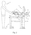
- FIGS 1-11 show non-limiting examples of a nozzle manipulator assembly and associated components, in accordance with embodiments of the invention.
- a manipulator assembly 10 for supporting and moving a nozzle segment during welding, brazing or other inspection or repair is schematically illustrated in FIGURES 1 and 2.
- the manipulator assembly includes a manipulator 12 and a nozzle segment supporting fixture 14. The manipulator is disposed to allow a nozzle segment 16 supported in the nozzle fixture 14 to be moved vertically as shown by arrow V and horizontally over, e.g., a bench 18.
- horizontal movement is accomplished by providing a manipulator 12 including a vertical segment 20 and a horizontal segment 22, the horizontal segment 22 being pivotably mounted (B) with respect to the vertical segment 20.
- a nozzle segment fixture mount 24 is in turn pivotally mounted (D) to the distal end 26 of the horizontal segment 22.
- the vertical segment 20 of the manipulator 12 in the illustrated embodiment is comprised of a pillar or post and base assembly 28 and a support tube 30 that is selectively displaced upwardly and downwardly along the post according to actuation of the hydraulic cylinder 32.
- the horizontal segment 22 is mounted to pivot about axis A of the vertical segment 20.
- the horizontal segment 22 includes a generally cylindrical receptacle 34 that is rotatably disposed on a sleeve 36 seated on the support tube 30 so that as the support tube 30 is raised and lowered (V) by the hydraulic cylinder 32, the proximal end 38 of the horizontal segment 22 is likewise raised and lowered.
- the fixture mount 24 is mounted to pivot about axis C at the distal end of the horizontal segment.
- the distal end 26 of the horizontal segment 22 includes a vertical oriented sleeve 40 to which the mounting assembly of the nozzle segment fixture is pivotally mounted as with the cylindrical bands 42,44 schematically depicted in FIGURE 2 and 4.
- movement of the nozzle segment fixture 14 and mount 12 about pivot C and movement of horizontal segment 22 about pivot A is effected manually.
- the rotational axes are supported on taper roller bearings with load controls to regulate ease of manual movement.
- the rotational axes also advantageously have locks (not shown in detail) in order to immobilize each axis independently. It is to be understood, however, that pivoting movement of the horizontal segment 22 and/or of the fixture mount 24 can be automated without departing from this invention.
- the horizontal segment 22 is schematically depicted as being of fixed length, those skilled in the art will appreciate that the horizontal arm can be formed from e.g., telescoping tubes to selectively provide for elongation and contraction of the horizontal arm along its axis. Extension of the horizontal arm can be automated by the inclusion of a suitable hydraulic cylinder or other drive mechanism(s) known in the art.
- the manipulator 12 and fixture 14 are adapted to support and manipulate a nozzle segment 16 weighing, for example, in excess of two hundred pounds. Therefore, in the illustrated example embodiment, the fixture 14 is configured as a rigid support to resist bending loads due to the cantilever support of the nozzle segment with respect to the horizontal segment 22. Furthermore, in an example embodiment of the invention, more than one nozzle segment fixture 14,114 may be provided to be selectively mounted to the manipulator 12 to accommodate nozzle segments of differing sizes/lengths.
- the nozzle segment fixtures 14,114 in the illustrated embodiments are generally U-shaped having a base 50,150 mounted to the fixture mount 24 and first and second arms 52,54;152,154 extending horizontally therefrom for being secured to respective radial ends of the nozzle segment.
- interchangeable tooling or ears 56,58;156,158 that are nozzle specific are provided to be selectively secured to each arm of the fixture.
- the interchangeable tooling 56,58;156,158 is specific to the nozzle segment configuration, and the fixtures 14,114 are respectively configured for accepting a variety of nozzles of generally similar size/length.
- the interchangeable tooling is mounted to the fixture arms so that the nozzle segment, once secured to the tooling, can be selectively rotated (N) with respect to the fixture arms.
- a bearing structure for rotating the nozzle is designed so as to preclude free rotation of the supported part, so that manual intervention is required to effect rotation of the nozzle segment.
- the nozzle segment may then be locked in a particular orientation so that unintended rotation is precluded.
- selective, powered movement in this case rotation of the nozzle segment, can be accommodated by providing a suitable drive mechanism for selectively rotating the nozzle specific tooling with respect to the fixture arms.
- the work bench 18 over which the nozzle segment 16 is suspended by the fixture 14,114 is a downdraft table having an opening or cutout 19, which will generally have a grate (not shown) therein, through which air is sucked downwards to remove e.g. dust particles and solvent fumes during braze application.
- the invention is not limited to the inclusion of a work bench, or the particulars thereof.
- the fixture mount 24 may be rotatably disposed with respect to horizontal so as to provide for a selective rotation (F) of the fixture 14,114 about an axis (E) perpendicular to pivot axis C.
- F a selective rotation
- E an axis perpendicular to pivot axis C.
- Rotation F about horizontal axis E also selectively facilitates attachment of the nozzle to the fixture.
- a foot pedal is used to control the hydraulic cylinder 32 for lifting and lowering the horizontal segment 22 of the manipulator 12.
- a two button controller is used, e.g. with an up button and a down button that are selectively depressed for corresponding control of the hydraulic cylinder 32.
Landscapes
- Engineering & Computer Science (AREA)
- Mechanical Engineering (AREA)
- General Engineering & Computer Science (AREA)
- Physics & Mathematics (AREA)
- Optics & Photonics (AREA)
- Chemical & Material Sciences (AREA)
- Combustion & Propulsion (AREA)
- Manipulator (AREA)
- Automatic Assembly (AREA)
- Turbine Rotor Nozzle Sealing (AREA)
Abstract
Description
- The present invention relates to turbine repair engineering and, more particularly, to a manipulator for manipulating a nozzle assembly of a turbine during brazing and welding.
- Nozzles, which typically weigh up to 200 pounds, cannot be safely manipulated by hand on a work bench. Furthermore, attempts to move a nozzle assembly can result in damage to the parts and injury to the operator.
- A manipulator is provided in accordance with an example embodiment of the invention to support a nozzle segment, for example from a gas turbine or from a steam turbine, and allow it to be moved vertically, horizontally and rotated for proper positioning, and then held motionless during welding or brazing.
- Thus, the invention may be embodied in a manipulator assembly for supporting and manipulating a nozzle segment, comprising: a manipulator including a vertical support member and a horizontal support member, the vertical support member being mounted for selective vertical displacement relative to a base, the horizontal support member being operatively coupled at a proximal end thereof to said vertical support member so as to be vertically displaced therewith and so as to be pivotable about a vertical axis of said vertical support member; and a nozzle segment fixture, said fixture being operatively coupled to a distal end of said horizontal support member and having coupling components respectively complimentary to first and second radial ends of a nozzle segment to selectively engage the nozzle segment.
- The invention may also be embodied in a method of manipulating a nozzle segment during brazing, welding and/or inspection, comprising: providing a manipulator including a vertical support member, a horizontal support member, and a nozzle segment fixture operatively coupled to a distal end of said horizontal support member, the vertical support member being mounted for selective vertical displacement relative to a base, the horizontal support member being operatively coupled at a proximal end thereof to said vertical support member so as to be vertically displaced therewith and so as to be pivotable about a vertical axis of said vertical support member; coupling a nozzle segment at each longitudinal end thereof to said nozzle segment fixture; and selectively at least one (a) a vertically displacing said vertical support member and (b) pivoting said horizontal support member about a vertical axis of said vertical support member so as to selectively, vertically and horizontally displace said nozzle segment fixture with respect to a work surface.
- These and other objects and advantages of this invention, will be more completely understood and appreciated by careful study of the following more detailed description of the presently preferred exemplary embodiments of the invention, provided by way of example only, taken in conjunction with the accompanying drawings, in which:
- FIGURE 1 is a schematic top plan view of a nozzle manipulator assembly supporting a nozzle segment over a bench according to an example embodiment of the invention;
- FIGURE 2 is a side elevational view of the manipulator assembly of FIGURE 1;
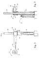
- FIGURE 3 is a front view of a manipulator embodying the invention with the nozzle segment supporting fixture omitted for clarity;
- FIGURE 4 is a view taken along line 4-4 of FIGURE 3;
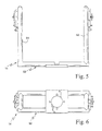
- FIGURE 5 is a plan view of a nozzle segment supporting fixture according to an example embodiment of the invention with nozzle specific tooling omitted for clarity;
- FIGURE 6 is a rear elevational view of the fixture of FIGURE 5;
- FIGURE 7 is a perspective view, from the rear and above, of the fixture of FIGURE 5, with tooling omitted for clarity;
- FIGURE 8 is a plan view of another nozzle segment supporting fixture including examples of nozzle specific tooling;
- FIGURE 9 is a rear elevational view of the fixture and tooling of FIGURE 8;
- FIGURE 10 is a side elevational view of the fixture and tooling of FIGURE 9; and
- FIGURE 11 is a view taken along line 11-11 of FIGURE 10.
- Figures 1-11 show non-limiting examples of a nozzle manipulator assembly and associated components, in accordance with embodiments of the invention. A
manipulator assembly 10 for supporting and moving a nozzle segment during welding, brazing or other inspection or repair is schematically illustrated in FIGURES 1 and 2. As illustrated therein, in an example embodiment of the invention, the manipulator assembly includes amanipulator 12 and a nozzlesegment supporting fixture 14. The manipulator is disposed to allow anozzle segment 16 supported in thenozzle fixture 14 to be moved vertically as shown by arrow V and horizontally over, e.g., abench 18. In the illustrated example embodiment, horizontal movement is accomplished by providing amanipulator 12 including avertical segment 20 and ahorizontal segment 22, thehorizontal segment 22 being pivotably mounted (B) with respect to thevertical segment 20. In this embodiment, a nozzlesegment fixture mount 24 is in turn pivotally mounted (D) to thedistal end 26 of thehorizontal segment 22. Thus, simultaneous pivoting movement about axis A and axis C, as shown by arrows B and D, results in movement of thenozzle segment fixture 14 in a horizontal plane, while maintaining the orientation of thenozzle segment 16 with respect to the operator X. - The
vertical segment 20 of themanipulator 12 in the illustrated embodiment is comprised of a pillar or post andbase assembly 28 and asupport tube 30 that is selectively displaced upwardly and downwardly along the post according to actuation of thehydraulic cylinder 32. - As mentioned above, the
horizontal segment 22 is mounted to pivot about axis A of thevertical segment 20. To this end, in the illustrated example embodiment, thehorizontal segment 22 includes a generallycylindrical receptacle 34 that is rotatably disposed on asleeve 36 seated on thesupport tube 30 so that as thesupport tube 30 is raised and lowered (V) by thehydraulic cylinder 32, theproximal end 38 of thehorizontal segment 22 is likewise raised and lowered. As mentioned above, thefixture mount 24 is mounted to pivot about axis C at the distal end of the horizontal segment. To this end, in the illustrated example embodiment, thedistal end 26 of thehorizontal segment 22 includes a verticaloriented sleeve 40 to which the mounting assembly of the nozzle segment fixture is pivotally mounted as with thecylindrical bands - In the illustrated example embodiment, movement of the
nozzle segment fixture 14 andmount 12 about pivot C and movement ofhorizontal segment 22 about pivot A is effected manually. Further, in an example embodiment the rotational axes are supported on taper roller bearings with load controls to regulate ease of manual movement. The rotational axes also advantageously have locks (not shown in detail) in order to immobilize each axis independently. It is to be understood, however, that pivoting movement of thehorizontal segment 22 and/or of thefixture mount 24 can be automated without departing from this invention. Furthermore, although thehorizontal segment 22 is schematically depicted as being of fixed length, those skilled in the art will appreciate that the horizontal arm can be formed from e.g., telescoping tubes to selectively provide for elongation and contraction of the horizontal arm along its axis. Extension of the horizontal arm can be automated by the inclusion of a suitable hydraulic cylinder or other drive mechanism(s) known in the art. - As noted above, the
manipulator 12 andfixture 14 are adapted to support and manipulate anozzle segment 16 weighing, for example, in excess of two hundred pounds. Therefore, in the illustrated example embodiment, thefixture 14 is configured as a rigid support to resist bending loads due to the cantilever support of the nozzle segment with respect to thehorizontal segment 22. Furthermore, in an example embodiment of the invention, more than one nozzle segment fixture 14,114 may be provided to be selectively mounted to themanipulator 12 to accommodate nozzle segments of differing sizes/lengths. The nozzle segment fixtures 14,114 in the illustrated embodiments are generally U-shaped having a base 50,150 mounted to thefixture mount 24 and first andsecond arms - To secure the nozzles respectively to the nozzle fixture, interchangeable tooling or
ears interchangeable tooling - In the illustrated example embodiment, the
work bench 18 over which thenozzle segment 16 is suspended by the fixture 14,114 is a downdraft table having an opening orcutout 19, which will generally have a grate (not shown) therein, through which air is sucked downwards to remove e.g. dust particles and solvent fumes during braze application. The invention is not limited to the inclusion of a work bench, or the particulars thereof. - To provide yet a further degree of freedom, the
fixture mount 24 may be rotatably disposed with respect to horizontal so as to provide for a selective rotation (F) of the fixture 14,114 about an axis (E) perpendicular to pivot axis C. This allows the nozzle segment to be selectively inclined at an angle to horizontal if deemed necessary or desirable to facilitate welding, brazing or inspection. Rotation F about horizontal axis E also selectively facilitates attachment of the nozzle to the fixture. Once again, manual rotation is proposed, with a locking mechanism to selectively preclude manual rotation, but powered rotation is an alternative. - In one example embodiment of the invention a foot pedal is used to control the
hydraulic cylinder 32 for lifting and lowering thehorizontal segment 22 of themanipulator 12. In another example, a two button controller is used, e.g. with an up button and a down button that are selectively depressed for corresponding control of thehydraulic cylinder 32. - While the invention has been described in connection with what is presently considered to be the most practical and preferred embodiment, it is to be understood that the invention is not to be limited to the disclosed embodiment, but on the contrary, is intended to cover various modifications and equivalent arrangements included within the spirit and scope of the appended claims.
Claims (10)
- A manipulator assembly (10) for supporting and manipulating a nozzle segment (16), comprising:a manipulator including a vertical support member (20) and a horizontal support member (22), the vertical support member being mounted for selective vertical displacement (V) relative to a base (28), the horizontal support member being operatively coupled at a proximal end (38) thereof to said vertical support member so as to be vertically displaced therewith and so as to be pivotable (B) about a vertical axis (A) of said vertical support member; anda nozzle segment fixture (14,114), said fixture being operatively coupled to a distal end (26) of said horizontal support member and having coupling components (56,58;156,158) respectively complimentary to first and second radial ends of a nozzle segment (16) to selectively engage the nozzle segment.
- A manipulator assembly as in claim 1, wherein said fixture comprises a base (50,150) and first and second arms (52,54;152,154) projecting therefrom, said coupling components being mounted to said arms.
- A manipulator assembly as in claim 1, wherein said coupling components are selectively rotatable (N) with respect to said arms of said fixture so that a nozzle segment (16) secured thereto can be rotated with respect to said fixture (14,114).
- A manipulator assembly as in claim 1, wherein said fixture is operatively coupled to said distal end of said horizontal support member so as to be pivotable with respect thereto.
- A manipulator assembly as in claim 4, wherein said fixture is pivotable (D) with respect to said horizontal support member about a pivot axis (C) that is substantially parallel to said vertical axis.
- A manipulator assembly as in claim 1, wherein a fixture mount (24) is interposed between said fixture and said horizontal support member and said fixture mount is pivotable (D) with respect to said horizontal support member about a pivot axis (C) that is substantially parallel to said vertical axis.
- A manipulator assembly as in claim 6, wherein said fixture mount is fixed at one end to said fixture (14,114) and pivotally coupled at the other end thereof to said horizontal support member (22) and wherein said fixture mount is rotatable between said respective ends so that said fixture can be rotated (F) about an axis (E) generally perpendicular to said pivot axis (C).
- A method of manipulating a nozzle segment during brazing, welding and/or inspection, comprising:providing a manipulator (10) including a vertical support member (20), a horizontal support member (22), and a nozzle segment fixture (14,114) operatively coupled to a distal end (26) of said horizontal support member, the vertical support member being mounted for selective vertical displacement (V) relative to a base (28), the horizontal support member (22) being operatively coupled at a proximal end (38) thereof to said vertical support member (20) so as to be vertically displaced therewith and so as to be pivotable (B) about a vertical axis (A) of said vertical support member;coupling a nozzle segment (16) at each longitudinal end thereof to said nozzle segment fixture (14,114); andselectively at least one (a) a vertically displacing (V) said vertical support member and (b) pivoting (B) said horizontal support member about a vertical axis of said vertical support member so as to selectively, vertically and horizontally displace said nozzle segment fixture with respect to a work surface.
- A method as in claim 8, wherein said nozzle segment fixture comprises a base (50,150) and first and second arms (52,54;152,154), and coupling components (56,58;156,158) complementary to said nozzle segment for selectively engaging the nozzle segment, and further comprising selectively rotating (N) said coupling components with respect to said arms of said nozzle segment fixture so that a nozzle segment secured thereto is rotated with respect to said nozzle segment fixture.
- A method as in claim 8, further comprising selectively pivoting (D) said nozzle segment fixture with respect to a distal end (26) of said horizontal support member.
Applications Claiming Priority (1)
| Application Number | Priority Date | Filing Date | Title |
|---|---|---|---|
| US11/377,217 US20070234549A1 (en) | 2006-03-17 | 2006-03-17 | Braze/weld manipulator and method of manipulating nozzles |
Publications (2)
| Publication Number | Publication Date |
|---|---|
| EP1844895A2 true EP1844895A2 (en) | 2007-10-17 |
| EP1844895A3 EP1844895A3 (en) | 2007-12-19 |
Family
ID=38235342
Family Applications (1)
| Application Number | Title | Priority Date | Filing Date |
|---|---|---|---|
| EP07104259A Withdrawn EP1844895A3 (en) | 2006-03-17 | 2007-03-15 | Braze/weld manipulator and method of manipulating nozzles |
Country Status (6)
| Country | Link |
|---|---|
| US (1) | US20070234549A1 (en) |
| EP (1) | EP1844895A3 (en) |
| JP (1) | JP2007253236A (en) |
| KR (1) | KR20070094542A (en) |
| CN (1) | CN101036980A (en) |
| RU (1) | RU2007109728A (en) |
Cited By (1)
| Publication number | Priority date | Publication date | Assignee | Title |
|---|---|---|---|---|
| CN104097008A (en) * | 2014-07-15 | 2014-10-15 | 中国南方航空工业(集团)有限公司 | Fixing fixture and machining method for fuel spray nozzles |
Families Citing this family (6)
| Publication number | Priority date | Publication date | Assignee | Title |
|---|---|---|---|---|
| KR100920967B1 (en) * | 2008-02-11 | 2009-10-09 | 주식회사 무진기연 | Rotor shaft support stand with self-correction function |
| US7934302B2 (en) | 2008-12-31 | 2011-05-03 | General Electric Company | Apparatus and method for removing compressor blades |
| JP5625505B2 (en) * | 2010-06-04 | 2014-11-19 | トヨタ車体株式会社 | Welding auxiliary device |
| US10300546B2 (en) | 2017-01-27 | 2019-05-28 | United Technologies Corporation | Spherical articulating fixture |
| DE102021126366A1 (en) | 2021-10-12 | 2023-04-13 | Purem GmbH | Modular workstation |
| CN116329687B (en) * | 2023-04-27 | 2025-07-22 | 中国航发动力股份有限公司 | Vacuum brazing method for nozzle shell assembly |
Citations (1)
| Publication number | Priority date | Publication date | Assignee | Title |
|---|---|---|---|---|
| EP1607581A1 (en) | 2004-06-02 | 2005-12-21 | General Electric Company | Method and apparatus for fabricating a turbine nozzle assembly |
Family Cites Families (22)
| Publication number | Priority date | Publication date | Assignee | Title |
|---|---|---|---|---|
| US979305A (en) * | 1910-05-06 | 1910-12-20 | Charlie D Hunt | Wipe-joint pipe-holder. |
| US1550651A (en) * | 1921-06-25 | 1925-08-18 | James A Charter | Metal-wheel-welding machine |
| US1611305A (en) * | 1925-06-25 | 1926-12-21 | Alois P Prendergast | Universal combination interlocking and clamping device |
| US2602990A (en) * | 1947-08-05 | 1952-07-15 | Thomas C Ferguson | Radiator positioner |
| US2596401A (en) * | 1947-09-27 | 1952-05-13 | Hines Flask Company | Flask handling device |
| US3066930A (en) * | 1959-04-20 | 1962-12-04 | Walter I Chinnick | Holding tongs |
| US3301547A (en) * | 1964-06-18 | 1967-01-31 | Jordan Charles Ray | Means for handling radiators for repairs |
| US3595556A (en) * | 1969-07-25 | 1971-07-27 | Paul Schonauer | Holding device |
| US4317560A (en) * | 1979-12-26 | 1982-03-02 | Troyer Wade E | Work manipulator |
| US4527942A (en) * | 1982-08-25 | 1985-07-09 | Intest Corporation | Electronic test head positioner for test systems |
| JPS61146430A (en) * | 1984-12-20 | 1986-07-04 | Honda Motor Co Ltd | Holder structure for assembly of component elements |
| US5092572A (en) * | 1990-10-05 | 1992-03-03 | Anstat, Inc. | Allograft vise |
| US5918867A (en) * | 1995-07-31 | 1999-07-06 | Goodyear; Eugene L. | Multiple axis mounting unit |
| US5944896A (en) * | 1997-09-24 | 1999-08-31 | Lawson Screen Products, Inc. | Adjustable support for print screens |
| US6165542A (en) * | 1998-12-23 | 2000-12-26 | United Technologies Corporation | Method for fabricating and inspecting coatings |
| US6874737B1 (en) * | 1999-08-03 | 2005-04-05 | Thomas Madelone | Universal fixture system and base therefor |
| US6546616B2 (en) * | 2000-12-15 | 2003-04-15 | Bell Helicopter Textron Inc. | Six-axis alignment and installation tool |
| US6560890B1 (en) * | 2002-02-21 | 2003-05-13 | General Electric Company | Fixture for locating and clamping a part for laser drilling |
| US6648318B1 (en) * | 2002-06-06 | 2003-11-18 | Oetlinger Tool Engineering Co., Inc. | Welding jig |
| US6883792B2 (en) * | 2002-09-16 | 2005-04-26 | Honda Motor Co., Ltd. | Workpiece positioner and method |
| US7032279B2 (en) * | 2002-10-18 | 2006-04-25 | General Electric Company | Apparatus and methods for repairing compressor airfoils in situ |
| US7429035B2 (en) * | 2005-09-29 | 2008-09-30 | Wprwmdm, L.L.C. | Equipment handling apparatus |
-
2006
- 2006-03-17 US US11/377,217 patent/US20070234549A1/en not_active Abandoned
-
2007
- 2007-03-15 EP EP07104259A patent/EP1844895A3/en not_active Withdrawn
- 2007-03-16 JP JP2007067946A patent/JP2007253236A/en not_active Withdrawn
- 2007-03-16 CN CNA2007101006289A patent/CN101036980A/en active Pending
- 2007-03-16 KR KR1020070025941A patent/KR20070094542A/en not_active Withdrawn
- 2007-03-16 RU RU2007109728/02A patent/RU2007109728A/en not_active Application Discontinuation
Patent Citations (1)
| Publication number | Priority date | Publication date | Assignee | Title |
|---|---|---|---|---|
| EP1607581A1 (en) | 2004-06-02 | 2005-12-21 | General Electric Company | Method and apparatus for fabricating a turbine nozzle assembly |
Cited By (2)
| Publication number | Priority date | Publication date | Assignee | Title |
|---|---|---|---|---|
| CN104097008A (en) * | 2014-07-15 | 2014-10-15 | 中国南方航空工业(集团)有限公司 | Fixing fixture and machining method for fuel spray nozzles |
| CN104097008B (en) * | 2014-07-15 | 2016-08-17 | 中国南方航空工业(集团)有限公司 | The stationary fixture of fuel nozzle and the processing method of fuel nozzle |
Also Published As
| Publication number | Publication date |
|---|---|
| JP2007253236A (en) | 2007-10-04 |
| CN101036980A (en) | 2007-09-19 |
| EP1844895A3 (en) | 2007-12-19 |
| US20070234549A1 (en) | 2007-10-11 |
| KR20070094542A (en) | 2007-09-20 |
| RU2007109728A (en) | 2008-09-27 |
Similar Documents
| Publication | Publication Date | Title |
|---|---|---|
| EP1844895A2 (en) | Braze/weld manipulator and method of manipulating nozzles | |
| CN102656089B (en) | Aircraft engine unit transport bracket | |
| CN108706333B (en) | Tunnel steel arch installing manipulator and manipulator working platform | |
| CN113565454B (en) | Pipe rod loading and unloading device for vertical catwalk for workover treatment and use method | |
| US5681033A (en) | Workpiece pick-up jig and positioning tool | |
| JP3559244B2 (en) | Rod demolition machine | |
| CN210704851U (en) | Robot for mounting and dismounting building outer frame and outer wall guide rail | |
| JP7142041B2 (en) | Fume suction mobile welding equipment | |
| JP5095617B2 (en) | Handling equipment as a component part of a kite | |
| JP5260028B2 (en) | Work mounting method on work mounting device, work removing method from work mounting device, work holding device for work mounting device, work support for work mounting device, and work mounting system | |
| JP2632630B2 (en) | Temporary welding jig for steel pipes with flanges at both ends | |
| JP3766452B2 (en) | Blow pipe replacement machine | |
| JPH0834600A (en) | Adaptable crane for work stage which can run | |
| JP4422814B2 (en) | Auxiliary machine bearing attachment and detachment device | |
| CN120502856B (en) | Open-close type tool joint laser welding device | |
| JP2000351140A (en) | Detachment guide mechanism and detachment guide method for plasticizing unit of vertical injection molding machine | |
| JP6555012B2 (en) | Work machine | |
| JP5691742B2 (en) | Piston extraction device | |
| CN218426639U (en) | Welding device | |
| WO2000040498A1 (en) | Mobile crane device with auxiliary jib | |
| JP2001198697A (en) | Welding workbench | |
| JP2572738B2 (en) | Pile driving and pulling machine | |
| JP2000072375A (en) | Attachment for crane | |
| CN118768784A (en) | A bogie center beam welding device | |
| JPS6236756B2 (en) |
Legal Events
| Date | Code | Title | Description |
|---|---|---|---|
| PUAI | Public reference made under article 153(3) epc to a published international application that has entered the european phase |
Free format text: ORIGINAL CODE: 0009012 |
|
| AK | Designated contracting states |
Kind code of ref document: A2 Designated state(s): AT BE BG CH CY CZ DE DK EE ES FI FR GB GR HU IE IS IT LI LT LU LV MC MT NL PL PT RO SE SI SK TR |
|
| AX | Request for extension of the european patent |
Extension state: AL BA HR MK YU |
|
| PUAL | Search report despatched |
Free format text: ORIGINAL CODE: 0009013 |
|
| AK | Designated contracting states |
Kind code of ref document: A3 Designated state(s): AT BE BG CH CY CZ DE DK EE ES FI FR GB GR HU IE IS IT LI LT LU LV MC MT NL PL PT RO SE SI SK TR |
|
| AX | Request for extension of the european patent |
Extension state: AL BA HR MK YU |
|
| 17P | Request for examination filed |
Effective date: 20080619 |
|
| AKX | Designation fees paid |
Designated state(s): CH DE FR GB LI |
|
| 17Q | First examination report despatched |
Effective date: 20080901 |
|
| STAA | Information on the status of an ep patent application or granted ep patent |
Free format text: STATUS: THE APPLICATION IS DEEMED TO BE WITHDRAWN |
|
| 18D | Application deemed to be withdrawn |
Effective date: 20101001 |