EP1843587A1 - Method for the frame-rate conversion of a digital video signal and related apparatus - Google Patents
Method for the frame-rate conversion of a digital video signal and related apparatus Download PDFInfo
- Publication number
- EP1843587A1 EP1843587A1 EP06425235A EP06425235A EP1843587A1 EP 1843587 A1 EP1843587 A1 EP 1843587A1 EP 06425235 A EP06425235 A EP 06425235A EP 06425235 A EP06425235 A EP 06425235A EP 1843587 A1 EP1843587 A1 EP 1843587A1
- Authority
- EP
- European Patent Office
- Prior art keywords
- rate
- video sequence
- images
- frame
- image
- Prior art date
- Legal status (The legal status is an assumption and is not a legal conclusion. Google has not performed a legal analysis and makes no representation as to the accuracy of the status listed.)
- Withdrawn
Links
Images


Classifications
-
- H—ELECTRICITY
- H04—ELECTRIC COMMUNICATION TECHNIQUE
- H04N—PICTORIAL COMMUNICATION, e.g. TELEVISION
- H04N7/00—Television systems
- H04N7/01—Conversion of standards, e.g. involving analogue television standards or digital television standards processed at pixel level
- H04N7/0135—Conversion of standards, e.g. involving analogue television standards or digital television standards processed at pixel level involving interpolation processes
- H04N7/014—Conversion of standards, e.g. involving analogue television standards or digital television standards processed at pixel level involving interpolation processes involving the use of motion vectors
-
- H—ELECTRICITY
- H04—ELECTRIC COMMUNICATION TECHNIQUE
- H04N—PICTORIAL COMMUNICATION, e.g. TELEVISION
- H04N7/00—Television systems
- H04N7/01—Conversion of standards, e.g. involving analogue television standards or digital television standards processed at pixel level
- H04N7/0105—Conversion of standards, e.g. involving analogue television standards or digital television standards processed at pixel level using a storage device with different write and read speed
Definitions
- the present invention relates to techniques for frame-rate conversion of a video sequence of digital images from variable to constant.
- the invention has been developed with particular attention paid to its possible application to the reproduction of video sequences in mobile terminals with capacity of audio-video conversation, for example, for videoconferences.
- the scope of the invention is not, on the other hand, limited to this specific field of application: the invention is, in fact, applicable to all systems for processing video sequences in which conditions of operation arise of the same type as the ones described in what follows.
- the frame-rate of a video sequence is constituted by the temporal frequency of said sequence, i.e., by the number of digital images, organized in frames, per second that form the sequence itself.
- Figure 1 shows a block diagram representing a system for frame-rate conversion, which comprises a source video system 100, which produces at output a video sequence SV of images with variable frame-rate v, and a destination video system 120, which is instead configured for receiving a video sequence SC at , constant and pre-set frame-rate c. Consequently, in order to enable transmission of video sequences from the source video system 100 to the terminal video system 120, there is provided a frame-rate converter apparatus 110, which receives at input the video sequence SV with variable frame-rate v and generates at output the conversion into a video sequence SC with constant and pre-set frame-rate c.
- the source video system 100 corresponds to a video decoder, which operates, for example, but not only, according to a standard selected from among video standards such as MPEG-2, MPEG-4, H.264, DivX, Windows Media Video.
- a video decoder which operates, for example, but not only, according to a standard selected from among video standards such as MPEG-2, MPEG-4, H.264, DivX, Windows Media Video.
- the source video system 100 is, for example, represented by a decoder, it receives a bitstream, compressed through a channel, whether wired or wireless, which introduces errors and/or variable delay or jitter, so that, according to the delay introduced by the channel itself, the source video system 100 is able to decode the images contained in the bitstream at a higher rate or at a lower rate.
- the terminal video system 120 can be, for example, a viewing device, i.e., a display, with a pre-set refresh frequency, capable of receiving and displaying a pre-set number of images per second corresponding to the pre-set constant frame-rate c.
- a viewing device i.e., a display
- a pre-set refresh frequency capable of receiving and displaying a pre-set number of images per second corresponding to the pre-set constant frame-rate c.
- the frame-rate converter apparatus can operate according to the known simple method of conversion from a variable frame-rate v to a constant frame-rate c, which envisages the following conditions:
- the European patent application No. EP-A-0 637 889 describes a method for varying the frame-rate of a video sequence by means of motion-compensated interpolation. However, the method is not dynamic and has the only purpose of doubling the frame-rate of the video sequence to be displayed. A similar method for frame-rate doubling is also known from the European patent application No. EP-A-0 475 499 .
- US patent application No. US2004/156624 describes a system capable of dynamic adaptation of the rate of display of a digital video sequence via a buffering operation, i.e., an operation of temporary storage, and subsequent check on the buffer. However, said system does not render the output frame-rate constant.
- the purpose of the present invention is to provide a solution capable of converting progressively and adaptively the frame-rate from variable to constant preventing both the loss of images and repeated display.
- said purpose is achieved thanks to a method for conversion of an input video sequence comprising digital images organized in frames and operating at a variable frame-rate into an output video sequence operating at a pre-set constant frame-rate having the characteristics recalled specifically in the ensuing claims.
- the invention also relates to the corresponding conversion apparatus, as well as the corresponding computer program product, directly loadable into the memory of a computer such as a processor and comprising software code portions for performing the method according to the invention when the product is run on a computer.
- the solution according to the invention envisages providing a frame buffer, which receives at input the video sequence with variable frame-rate and temporarily stores the images thereof. Said frame buffer is emptied at an emptying rate, which can be adjusted under the control of a control module, and is sent onto an interpolation module, which, via operations of motion-compensated interpolation, supplies the number of images necessary for maintaining the output frame-rate constant.
- the solution proposed herein provides an apparatus that is not subject to problems of overflow of the frame buffer, and, moreover, does not discard or add images, but interpolates them adaptively, and is hence able to make up for a variety of problems that can occur between a source terminal and a destination terminal, amongst which problems of jitter, problems of slowed-down reproduction, reconstruction of missing images, and need for fixed-rate oversampling.
- FIG. 2 shows a frame-rate apparatus designated as a whole by the reference number 210.
- Said converter apparatus 210 comprises a frame-buffer module 215 which receives at input the input video sequence SV with variable frame-rate v.
- Said frame-buffer module 215 is a buffer, or transit memory, that is able to contain up to a maximum number N of video images.
- Said frame-buffer module 215 is in particular a buffer of a FIFO (First-In/First-Out) type, so that the first image of the input video sequence SV introduced into the frame-buffer module 215 is also the first to be fetched.
- FIFO First-In/First-Out
- the conversion apparatus 210 further comprises a logic control module 220, which receives from the frame-buffer module 215 an item of information on a filling level b thereof, i.e., an item of information indicating a number of images of said input video sequence SV temporarily stored in said frame-buffer module 215, as well as an image-interpolation module 225, which is controlled in its operation by said logic control module 220 and receives from the frame-buffer module 215 an intermediate video sequence SF operating at an emptying rate f.
- Said emptying rate f is also in general a rate that varies according to the need, as will be described in greater detail in what follows.
- Said conversion apparatus 210 in particular as regards the image-interpolation module 225, can be implemented either by a dedicated hardware or by a software program run by a microprocessor, or else by any sharing of hardware and software resources whatsoever.
- the frame-buffer module 215 is filled by the input video sequence SV at the variable rate v, not known a priori, and is emptied at the emptying rate f, which is also variable, by the interpolation module 225.
- the filling level b of the frame-buffer module 215 corresponds to the number of images contained therein, a number which is comprised between zero and the maximum number of images N.
- the logic control module 220 has the task of determining at each instant in time said filling level b of the frame-buffer module 215, and, on the basis of its value, determining the emptying rate f, according to the following criteria:
- the logic control module 220 implements a procedure comprising the following operations, expressed in a formalism of programming pseudocode:
- Said procedure can be extended by defining a number of maximum threshold values SMAX (i) and minimum threshold values SMIN (i), and by defining a number of correction values k (i), which determine a number of values of the emptying rate f, as described in the following example:
- the image-interpolation module 225 receives at input a sequence of intermediate images SF at an emptying rate f and returns at output the sequence of output images SC with pre-set constant frame-rate c.
- the value assumed by said emptying rate f as a function of the filling level b is known through the logic control module 220.
- the task of the image-interpolation module 225 is to generate a number c of output images every number f of input images, interpolating the images available at input in the intermediate sequence SF.
- Each image in the output video sequence SC can be generated by interpolating in the intermediate sequence SF the input images closest in time, i.e., the immediately preceding image and the immediately subsequent one.
- the interpolation module 225 does not need in actual fact to perform any operation so that its output video sequence SC is equal to the intermediate video sequence SF.
- the input emptying rate f is lower than the output constant frame-rate c; hence the interpolation module 225 must produce a number of images higher than that of the images fetched by the frame-buffer module 215.
- a vector of input images 305 represent the images ⁇ I 0 , ..., I f-1 ⁇ belonging to the intermediate video sequence SF at input to the interpolation module 225
- a vector of output images 310 represents the images ⁇ O 0 , ..., O c-1 ⁇ belonging to the video sequence SC at output from the interpolation module 225.
- the input emptying rate f is higher than the output constant frame-rate c.
- the interpolation module 225 must produce a number of images lower than that of the images fetched by the frame-buffer module 215.
- Figure 3b shown in which is a vector of input images 305' that contains a number f of images ⁇ I 0 , ..., I f-1 ⁇ higher than the number c of output images ⁇ O 0 , ..., O c-1 ⁇ .
- the image-interpolation module 225 is able to generate an image, designated as a whole by O k , occurring at a display instant in time t k , given at least one image Ip preceding in time occurring at the previous instant t p (with t p ⁇ t k ) and at least one image I s subsequent in time occurring at the subsequent instant t s (with t s >t k ) via procedures of scaled motion-compensation and weighted filtering, where the scaling of the motion vectors and the filtering weight are proportional to the distance in time between images.
- the conversion ratio is hence 3 to 2 so that the interpolation module 225 must generate three output images every two input images.
- Figure 4 appearing in which are a time axis Tin of the input images and a time axis Tout of the output images.
- the times corresponding to the time axis Tout of the output images are multiplied by a scaling factor f/c equal to 2/3, i.e., 0.67, to obtain a new time reference, i.e., a scaled time axis T that corresponds to the axis of the input times Tin.
- a scaling factor f/c equal to 2/3, i.e. 0.67
- the second output image O 1 the display instant of which on the scaled axis T is 0.67, is obtained by interpolating the first input image I 0 and a second input image I 1 , attributing a lower weight to the first input image I 0 and a higher weight to the second input image I 1 .
- the second output image O 2 is obtained by interpolating the first input image I 1 and the second input image I 2 , assigning a higher weight to I 1 (0.67) and a lower weight to I 2 (0.33).
- the weight of the subsequent reference is T-floor (T), and that of the preceding reference is ceil (T)-T.
- the scaled time T at which the image generated at output O k occurs is represented by an integer, it is not necessary to carry out any interpolation, and the output image is obtained by copying the input image.
- the method can be readily extended to a number of preceding and subsequent reference images.
- Figure 5 shows in detail the architecture of the image-interpolation module 225, which comprises two memories M1 and M2 for recording the two input images, i.e., the preceding one I p and the subsequent one I s , to be interpolated.
- said two memories M1 and M2 coincide with the last two locations of the FIFO frame-buffer module 215 of Figure 2.
- a motion-estimation block 216 receives from said two memories M1 and M2 the two input images, performing on the basis thereof the bi-directional motion estimation.
- a filtering block 217 receives the output motion-estimation block 216 generating the output image.
- a control block 218, which operates under the control of the control module 220, performs the specific function of determining the weights of the two input images, i.e., the preceding one I p and subsequent one I s , with respect to the image O k to be reconstructed.
- a multiplexer 219 carries out a selection between its two inputs, which correspond to the output of the filtering block 217 or else to the contents of the memory M2, which is the last location of the FIFO memory containing the input image. According to the selection, the multiplexer 219, under the control of the module 220, returns at output the image reconstructed by interpolation or else the input image.
- Figure 6 represents a frame-rate conversion apparatus 400 that constitutes an alternative and preferred embodiment as compared to the frame-rate conversion apparatus 210 shown in Figure 2.
- the reference number 450 designates a video decoder.
- Said video decoder 450 which can be, for example, a video decoder operating according to the standard ITU H.264, in itself comprises a video-decoder buffer 455, which is used to store the images at input to the decoder 450 that are stored prior to the subsequent decoding by the video decoder 450 itself.
- Cascaded downstream of the video decoder 450 are the frame-buffer module 215 and the interpolation module 225, operating under the control of the logic control module 220.
- the logic control module 220 is provided to verify no longer the filling level b1 of the frame-buffer module 215, as in the conversion apparatus 210, but rather a filling level b1 of the video-decoder buffer 455, consequently controlling the instant of decoding of an image by the video decoder 450 to prevent overflow or underflow of the video-decoder buffer 455.
- f is the emptying rate of the video-decoder buffer 455 by the video decoder 450
- b1 is the filling level of the video-decoder buffer 455
- SMAX and SMIN are the two thresholds, respectively, the maximum one and the minimum one
- the frame buffer 215 set between the decoder 450 and the interpolation module 225 comprises only two memory locations, previously designated by M1 and M2, designed to store the two input images to be interpolated.
- the advantage of the solution implemented in the frame-rate conversion apparatus 400 shown in Figure 6 consists in memory saving, due to the fact that the images are stored in the compressed form within the video-decoder buffer 455, and are decoded only when necessary, following the commands of the control logic 220.
- Figure 7 hence shows a terminal source 510, which transmits encoded video data.
- a transmission network 500 receives said transmitted encoded video data and conveys them from the source terminal 510 to a destination terminal 520, which receives said encoded video data.
- the conversion apparatus 210 and 300 can be applied to a procedure of adaptive frame-rate conversion.
- the network 500 is subject to jitter, on account of which the destination terminal 520 does not have the possibility of receiving a constant stream of data.
- the destination terminal 520 is found to receive fewer data than expected, and hence reproduces a video sequence with a lower frame-rate than it should; at another instant the destination terminal 520 receives more data, and consequently can find itself having to discard some data if its own receiver buffer is full.
- the apparatus and the method proposed enable the destination terminal 520 to process the input images in such a way as to convert the sequence received, which has a variable frame-rate on account of jitter, into a sequence with constant bit-rate, which can then be reproduced correctly without display artefacts that would cause degradation in the service quality.
- the apparatus and method proposed are capable of carrying out the frame-rate conversion so as to be able to display a sequence at a constant frame-rate without artefacts, operating according to the procedures of motion-compensated interpolation described with reference to Figures 3 and 4 on bursts B and silent intervals S of the received images IR and stored images IV as represented in Figure 9.
- Another possible application regards the case of need for frame reconstruction.
- the network 500 is subject to data losses, so that the destination terminal 520 at the receiver end has not the possibility of receiving all the images sent on the network 500 by the source terminal 510 at the transmitter end.
- the system proposed can then carry out reconstruction of the missing images and propose a complete sequence of stored images IV.
- Another possible application regards the case of need for fixed-rate oversampling.
- the source terminal 510 at the transmitter end is forced to send a video sequence of transmitted images IT with a reduced frame-rate with respect to a sequence of original images IO, for example a halved frame-rate, as shown in Figure 11. If, however, the frame-rate of the sequence received at the destination terminal 520 is not able to satisfy the quality of the service required, the destination terminal 520 at the receiver end carries out, via the apparatus according to the invention, an oversampling of the input video sequence so as to obtain the appropriate frame-rate, as shown in Figure 11.
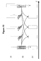
- the apparatus and method proposed can moreover be introduced in a system 600 comprising both video-decoding operations and audio-decoding operations, as shown in Figure 12.
- a demultiplexer 610 receives a sequence of audio-video data SAV and operates to direct the video sequence SV comprised in said sequence of audio-video data SAV to a video decoder 450, which decodes the compressed video data to display them on a display 620, whilst an audio sequence SA also comprised in said sequence of audio-video data SAV is sent to an audio decoder 550.
- a display device 620 for example the display of a mobile terminal of a mobile telecommunications network.
- the display device 620 could also be on a fixed terminal.
- the audio decoder 650 decodes the compressed audio data to send them in a constant-rate stream SCA to a loudspeaker 655, for example the loudspeaker of a mobile terminal.
- Said audio decoder 650 that carries out conversion of the audio-reproduction stream can in general adopt dejitter techniques, based upon a class of algorithms of time stretching of the data packets.
- the system 600 enables a continuous reproduction of a digital audio-video stream in the case where the compressed data are received through a network with errors and/or jitter.
- the system 600 comprises a reproduction-management or playout-manager block 630, which controls both the video decoder 450 and the audio decoder 650, performing at least the following three functions:
- the apparatus for frame-rate conversion of a video sequence of digital images hence advantageously enables adaptation of a sequence with variable frame-rate into a sequence with constant frame-rate, using a method of interpolation that avoids the need to discard or repeat roughly images for the purpose of adapting the frame-rate.
- the adoption of interpolation considerably improves the quality of the image and enables various other problems that arise in the transmission between a source terminal and a destination terminal to be overcome, such as problems of jitter, slowed-down reproduction, need for lost-frame reconstruction, need for fixed-rate oversampling.
- the combined use of a buffer and of an interpolator enables management of delays imposed by the network that are not known a priori and are of even very long time duration, without running any risk of overflow or underflow, with consequent loss of images, which would be obtained using the buffer alone.
- a possible buffer of very large dimensions for taking into account long delays would introduce in turn a constant delay proportional to the dimension of the buffer, said delay not being acceptable for some applications of practical importance, such as, for example, video conversation.
- the frame-rate conversion apparatus can readily be integrated in a system comprising both video decoding and audio decoding, enabling ease of synchronization, via adaptation of the frame-rate, of the video sequences with the audio sequences.
- interpolator used in the method and in the apparatus according to the invention can be indifferently chosen between various types of interpolators of images present in the literature
- an example of a possible interpolator that can be used as image-interpolation module is contained in the publication by Alfonso D., Bagni D., Moglia D. "Bidirectionally motion-compensated frame-rate up-conversion for H.264/AVC decoders", 41- 44, ELMAR, 2005, 47th International Symposium, June 8-10, 2005 .
Landscapes
- Engineering & Computer Science (AREA)
- Multimedia (AREA)
- Signal Processing (AREA)
- Television Systems (AREA)
Abstract
controlling (220) fetching of images (305, 305') from the temporarily stored input video sequence (SV) by adjusting an emptying rate (f) to form an intermediate video sequence (SF); and
carrying out an operation of motion-compensated interpolation (225) on the intermediate video sequence (SF) to form the output video sequence (SC) operating at a pre-set constant frame-rate (c), the emptying rate (f) being adjusted (220) as a function of a number (b; b1) of images of the input video sequence (SV) with variable frame-rate (v) temporarily stored (b; b1).
Description
- The present invention relates to techniques for frame-rate conversion of a video sequence of digital images from variable to constant.
- The invention has been developed with particular attention paid to its possible application to the reproduction of video sequences in mobile terminals with capacity of audio-video conversation, for example, for videoconferences. The scope of the invention is not, on the other hand, limited to this specific field of application: the invention is, in fact, applicable to all systems for processing video sequences in which conditions of operation arise of the same type as the ones described in what follows.
- By definition, the frame-rate of a video sequence is constituted by the temporal frequency of said sequence, i.e., by the number of digital images, organized in frames, per second that form the sequence itself.
- Figure 1 shows a block diagram representing a system for frame-rate conversion, which comprises a
source video system 100, which produces at output a video sequence SV of images with variable frame-rate v, and adestination video system 120, which is instead configured for receiving a video sequence SC at , constant and pre-set frame-rate c. Consequently, in order to enable transmission of video sequences from thesource video system 100 to theterminal video system 120, there is provided a frame-rate converter apparatus 110, which receives at input the video sequence SV with variable frame-rate v and generates at output the conversion into a video sequence SC with constant and pre-set frame-rate c. - In a typical scenario of application, the
source video system 100 corresponds to a video decoder, which operates, for example, but not only, according to a standard selected from among video standards such as MPEG-2, MPEG-4, H.264, DivX, Windows Media Video. In the case where thesource video system 100 is, for example, represented by a decoder, it receives a bitstream, compressed through a channel, whether wired or wireless, which introduces errors and/or variable delay or jitter, so that, according to the delay introduced by the channel itself, thesource video system 100 is able to decode the images contained in the bitstream at a higher rate or at a lower rate. Theterminal video system 120 can be, for example, a viewing device, i.e., a display, with a pre-set refresh frequency, capable of receiving and displaying a pre-set number of images per second corresponding to the pre-set constant frame-rate c. - The frame-rate converter apparatus can operate according to the known simple method of conversion from a variable frame-rate v to a constant frame-rate c, which envisages the following conditions:
- when the variable frame-rate v is higher than the constant frame-rate c, it is envisaged to eliminate the images in excess (frame-skipping operation) avoiding display thereof; and
- when the variable frame-rate v is lower than said constant frame-rate c, it is envisaged to repeat the input images (frame-repetition operation) a number of times.
- It is clear how both the operation of frame skipping and that of frame repetition cause evident and troublesome temporal display artefacts.
- Known from the US patent No.
US 5, 796, 439 is, for example, a method for reduction of the frame-rate of a video sequence by means of selective frame skipping. - The
European patent application No. EP-A-0 637 889 describes a method for varying the frame-rate of a video sequence by means of motion-compensated interpolation. However, the method is not dynamic and has the only purpose of doubling the frame-rate of the video sequence to be displayed. A similar method for frame-rate doubling is also known from theEuropean patent application No. EP-A-0 475 499 . - The
US patent application No. US2004/156624 describes a system capable of dynamic adaptation of the rate of display of a digital video sequence via a buffering operation, i.e., an operation of temporary storage, and subsequent check on the buffer. However, said system does not render the output frame-rate constant. - The purpose of the present invention is to provide a solution capable of converting progressively and adaptively the frame-rate from variable to constant preventing both the loss of images and repeated display.
- According to the present invention, said purpose is achieved thanks to a method for conversion of an input video sequence comprising digital images organized in frames and operating at a variable frame-rate into an output video sequence operating at a pre-set constant frame-rate having the characteristics recalled specifically in the ensuing claims. The invention also relates to the corresponding conversion apparatus, as well as the corresponding computer program product, directly loadable into the memory of a computer such as a processor and comprising software code portions for performing the method according to the invention when the product is run on a computer.
- The claims form an integral part of the technical teachings supplied herein in relation to the invention. Basically, in the currently preferred embodiment, the solution according to the invention envisages providing a frame buffer, which receives at input the video sequence with variable frame-rate and temporarily stores the images thereof. Said frame buffer is emptied at an emptying rate, which can be adjusted under the control of a control module, and is sent onto an interpolation module, which, via operations of motion-compensated interpolation, supplies the number of images necessary for maintaining the output frame-rate constant.
- As compared to the known solutions, the solution proposed herein provides an apparatus that is not subject to problems of overflow of the frame buffer, and, moreover, does not discard or add images, but interpolates them adaptively, and is hence able to make up for a variety of problems that can occur between a source terminal and a destination terminal, amongst which problems of jitter, problems of slowed-down reproduction, reconstruction of missing images, and need for fixed-rate oversampling.
- The invention will now be described, purely by way of non-limiting example, with reference to the annexed plate of drawings, in which:
- Figure 1, in itself corresponding to the known art, has already been described previously;
- Figure 2 shows a block diagram of an apparatus for frame-rate conversion according to the invention;
- Figure 3 shows a diagram corresponding to images used in a mode of operation of the apparatus according to the invention;
- Figure 4 shows a diagram corresponding to images used in a further mode of operation of the apparatus according to the invention;
- Figure 5 represents a block diagram of an interpolation module comprised in the conversion apparatus of Figure 1;
- Figure 6 shows a further embodiment of the conversion apparatus according to the invention;
- Figure 7 represents a working diagram of a context of application of the conversion apparatus according to the invention;
- Figure 8 represents a diagram of a first application of the conversion apparatus according to the invention;
- Figure 9 represents a diagram of a second application of the conversion apparatus according to the invention;
- Figure 10 represents a diagram of a third application of the conversion apparatus according to the invention;
- Figure 11 represents a diagram of a fourth application of the conversion apparatus according to the invention; and
- Figure 12 represents a block diagram of an architecture of an audio-video system designed to implement the conversion apparatus according to the invention.
- Figure 2 shows a frame-rate apparatus designated as a whole by the
reference number 210. Saidconverter apparatus 210 comprises a frame-buffer module 215 which receives at input the input video sequence SV with variable frame-rate v. Said frame-buffer module 215 is a buffer, or transit memory, that is able to contain up to a maximum number N of video images. Said frame-buffer module 215 is in particular a buffer of a FIFO (First-In/First-Out) type, so that the first image of the input video sequence SV introduced into the frame-buffer module 215 is also the first to be fetched. - The
conversion apparatus 210 further comprises alogic control module 220, which receives from the frame-buffer module 215 an item of information on a filling level b thereof, i.e., an item of information indicating a number of images of said input video sequence SV temporarily stored in said frame-buffer module 215, as well as an image-interpolation module 225, which is controlled in its operation by saidlogic control module 220 and receives from the frame-buffer module 215 an intermediate video sequence SF operating at an emptying rate f. Said emptying rate f is also in general a rate that varies according to the need, as will be described in greater detail in what follows. - Said
conversion apparatus 210, in particular as regards the image-interpolation module 225, can be implemented either by a dedicated hardware or by a software program run by a microprocessor, or else by any sharing of hardware and software resources whatsoever. - Operation of the
conversion apparatus 210 occurs in the way described in what follows. - The frame-
buffer module 215 is filled by the input video sequence SV at the variable rate v, not known a priori, and is emptied at the emptying rate f, which is also variable, by theinterpolation module 225. - The filling level b of the frame-
buffer module 215 corresponds to the number of images contained therein, a number which is comprised between zero and the maximum number of images N. - The
logic control module 220 has the task of determining at each instant in time said filling level b of the frame-buffer module 215, and, on the basis of its value, determining the emptying rate f, according to the following criteria: - should the filling level b of the frame-
buffer module 215 be higher than a pre-set maximum threshold value SMAX, this indicates the fact that the frame-buffer module 215 is being filled too fast so that it must be emptied faster than usual in order to avoid occurrence of overflow; in this case, the emptying rate f must be f = c+k, i.e., it must be equal to the sum of the constant frame-rate c to be obtained in the output video sequence SC and a pre-set correction value k; - should the filling level b of the frame-
buffer module 215 be less than a pre-set minimum threshold value SMIN, this indicates the fact that the frame-buffer module 215 is being filled too slowly so that it must be emptied more slowly than usual in order to avoid occurrence of underflow; in this case, the emptying rate f must be f = c-k, i.e., it must be equal to the difference between the constant frame-rate c to be obtained in the output video sequence SC and the pre-set correction value k; - should the filling level b of the frame-
buffer module 215 be comprised between the minimum threshold value SMIN and the maximum threshold value SMAX, there is no danger of occurrence of underflow or of overflow, so that the emptying rate f is set as f = c, i.e., equal to the constant rate c to be obtained in the output video sequence SC. - Basically, therefore, the
logic control module 220 implements a procedure comprising the following operations, expressed in a formalism of programming pseudocode:
- Said procedure can be extended by defining a number of maximum threshold values SMAX (i) and minimum threshold values SMIN (i), and by defining a number of correction values k (i), which determine a number of values of the emptying rate f, as described in the following example:

- The image-
interpolation module 225, as has been said, receives at input a sequence of intermediate images SF at an emptying rate f and returns at output the sequence of output images SC with pre-set constant frame-rate c. The value assumed by said emptying rate f as a function of the filling level b is known through thelogic control module 220. Hence, in other words, the task of the image-interpolation module 225 is to generate a number c of output images every number f of input images, interpolating the images available at input in the intermediate sequence SF. Each image in the output video sequence SC can be generated by interpolating in the intermediate sequence SF the input images closest in time, i.e., the immediately preceding image and the immediately subsequent one. - Three possible cases may arise:
- the emptying rate f is equal to the constant frame-rate c;
- the emptying rate f is lower than the constant frame-rate c; and
- the emptying rate f is higher than the constant frame-rate c.
- In the first case, the
interpolation module 225 does not need in actual fact to perform any operation so that its output video sequence SC is equal to the intermediate video sequence SF. - In the second case, the input emptying rate f is lower than the output constant frame-rate c; hence the
interpolation module 225 must produce a number of images higher than that of the images fetched by the frame-buffer module 215. - This case is represented in Figure 3a, where a vector of
input images 305 represent the images {I0, ..., If-1} belonging to the intermediate video sequence SF at input to theinterpolation module 225, whilst a vector ofoutput images 310 represents the images {O0, ..., Oc-1} belonging to the video sequence SC at output from theinterpolation module 225. - In the third case, the input emptying rate f is higher than the output constant frame-rate c. This means that the
interpolation module 225 must produce a number of images lower than that of the images fetched by the frame-buffer module 215. This case is represented in Figure 3b, shown in which is a vector of input images 305' that contains a number f of images {I0, ..., If-1} higher than the number c of output images {O0, ..., Oc-1}. - The image-
interpolation module 225 is able to generate an image, designated as a whole by Ok, occurring at a display instant in time tk, given at least one image Ip preceding in time occurring at the previous instant tp (with tp<tk) and at least one image Is subsequent in time occurring at the subsequent instant ts (with ts>tk) via procedures of scaled motion-compensation and weighted filtering, where the scaling of the motion vectors and the filtering weight are proportional to the distance in time between images. - By way of example, assuming an emptying rate f of 20 Hz and a required constant frame-rate c of 30 Hz, the conversion ratio is hence 3 to 2 so that the
interpolation module 225 must generate three output images every two input images. This case is represented in Figure 4, appearing in which are a time axis Tin of the input images and a time axis Tout of the output images. In order to bring the two axes Tin and Tout to the same scale, the times corresponding to the time axis Tout of the output images are multiplied by a scaling factor f/c equal to 2/3, i.e., 0.67, to obtain a new time reference, i.e., a scaled time axis T that corresponds to the axis of the input times Tin. For simplicity, reference will be made in what follows to said scaled time axis T. - It is clear that the first output image O0 is exactly the same as the first input image I0, since the display instant tk is the same.
- The second output image O1, the display instant of which on the scaled axis T is 0.67, is obtained by interpolating the first input image I0 and a second input image I1, attributing a lower weight to the first input image I0 and a higher weight to the second input image I1. The weight of said second input image I1 is calculated, in fact, as


- The second output image O2 is obtained by interpolating the first input image I1 and the second input image I2, assigning a higher weight to I1 (0.67) and a lower weight to I2 (0.33).
- In general, for each image generated at output Ok whereby the scaled time is T, the instant in time of the preceding reference is given by floor (T) and that of the subsequent reference is given by ceil (T).
- In addition, the weight of the subsequent reference is T-floor (T), and that of the preceding reference is ceil (T)-T.
- In the case where the scaled time T at which the image generated at output Ok occurs is represented by an integer, it is not necessary to carry out any interpolation, and the output image is obtained by copying the input image.
- The method can be readily extended to a number of preceding and subsequent reference images.
- Figure 5 shows in detail the architecture of the image-
interpolation module 225, which comprises two memories M1 and M2 for recording the two input images, i.e., the preceding one Ip and the subsequent one Is, to be interpolated. In effect, said two memories M1 and M2 coincide with the last two locations of the FIFO frame-buffer module 215 of Figure 2. - A motion-
estimation block 216 receives from said two memories M1 and M2 the two input images, performing on the basis thereof the bi-directional motion estimation. - A
filtering block 217 receives the output motion-estimation block 216 generating the output image. - A
control block 218, which operates under the control of thecontrol module 220, performs the specific function of determining the weights of the two input images, i.e., the preceding one Ip and subsequent one Is, with respect to the image Ok to be reconstructed. - A
multiplexer 219 carries out a selection between its two inputs, which correspond to the output of thefiltering block 217 or else to the contents of the memory M2, which is the last location of the FIFO memory containing the input image. According to the selection, themultiplexer 219, under the control of themodule 220, returns at output the image reconstructed by interpolation or else the input image. - Figure 6 represents a frame-
rate conversion apparatus 400 that constitutes an alternative and preferred embodiment as compared to the frame-rate conversion apparatus 210 shown in Figure 2. - In said figure, the
reference number 450 designates a video decoder. Saidvideo decoder 450, which can be, for example, a video decoder operating according to the standard ITU H.264, in itself comprises a video-decoder buffer 455, which is used to store the images at input to thedecoder 450 that are stored prior to the subsequent decoding by thevideo decoder 450 itself. Cascaded downstream of thevideo decoder 450 are the frame-buffer module 215 and theinterpolation module 225, operating under the control of thelogic control module 220. - In this case, the
logic control module 220 is provided to verify no longer the filling level b1 of the frame-buffer module 215, as in theconversion apparatus 210, but rather a filling level b1 of the video-decoder buffer 455, consequently controlling the instant of decoding of an image by thevideo decoder 450 to prevent overflow or underflow of the video-decoder buffer 455. - If f is the emptying rate of the video-
decoder buffer 455 by thevideo decoder 450, b1 is the filling level of the video-decoder buffer 455, and SMAX and SMIN are the two thresholds, respectively, the maximum one and the minimum one, the control can be implemented as in the previous case, i.e.:
- In this embodiment, the
frame buffer 215 set between thedecoder 450 and theinterpolation module 225 comprises only two memory locations, previously designated by M1 and M2, designed to store the two input images to be interpolated. - The advantage of the solution implemented in the frame-
rate conversion apparatus 400 shown in Figure 6 consists in memory saving, due to the fact that the images are stored in the compressed form within the video-decoder buffer 455, and are decoded only when necessary, following the commands of thecontrol logic 220. - The apparatus and methods described up to now afford multiple applications in streaming of video sequences.
- Some of said applications will now be described, with reference to the diagram shown in Figure 7, which represents the technical context in which said applications operate. Figure 7 hence shows a
terminal source 510, which transmits encoded video data. Atransmission network 500 receives said transmitted encoded video data and conveys them from thesource terminal 510 to adestination terminal 520, which receives said encoded video data. - The
conversion apparatus 210 and 300 can be applied to a procedure of adaptive frame-rate conversion. - In this case, it is assumed that the
network 500 is subject to jitter, on account of which thedestination terminal 520 does not have the possibility of receiving a constant stream of data. - In other words, at a given instant the
destination terminal 520 is found to receive fewer data than expected, and hence reproduces a video sequence with a lower frame-rate than it should; at another instant thedestination terminal 520 receives more data, and consequently can find itself having to discard some data if its own receiver buffer is full. - The apparatus and the method proposed enable the
destination terminal 520 to process the input images in such a way as to convert the sequence received, which has a variable frame-rate on account of jitter, into a sequence with constant bit-rate, which can then be reproduced correctly without display artefacts that would cause degradation in the service quality. - The situation is described in Figure 8, where a series of images received IR at different times is converted into a series of displayed images IV scanned at a regular time interval To.
- Another possible application is in the case of slowed-down reproduction.
- This can occur, for example, in the case where the
network 500 undergoes a type of delay such that the images are not received at regular intervals, but in packets of variable size, referred to as bursts, followed by silent intervals. - In a way similar to what occurs in the previous case, the apparatus and method proposed are capable of carrying out the frame-rate conversion so as to be able to display a sequence at a constant frame-rate without artefacts, operating according to the procedures of motion-compensated interpolation described with reference to Figures 3 and 4 on bursts B and silent intervals S of the received images IR and stored images IV as represented in Figure 9.
- Another possible application regards the case of need for frame reconstruction.
- In this case, it is assumed that the
network 500 is subject to data losses, so that thedestination terminal 520 at the receiver end has not the possibility of receiving all the images sent on thenetwork 500 by thesource terminal 510 at the transmitter end. - As is shown in Figure 10, therefore, some of the transmitted images IT become received images IR at the
destination terminal 520, which present various missing elements. - Thanks to the motion-compensated interpolation of the images, the system proposed can then carry out reconstruction of the missing images and propose a complete sequence of stored images IV.
- Another possible application regards the case of need for fixed-rate oversampling.
- In this case, it is assumed that the
network 500 is not able to guarantee a bandwidth sufficient to convey all the data that the terminals would wish to exchange. Consequently, thesource terminal 510 at the transmitter end is forced to send a video sequence of transmitted images IT with a reduced frame-rate with respect to a sequence of original images IO, for example a halved frame-rate, as shown in Figure 11. If, however, the frame-rate of the sequence received at thedestination terminal 520 is not able to satisfy the quality of the service required, thedestination terminal 520 at the receiver end carries out, via the apparatus according to the invention, an oversampling of the input video sequence so as to obtain the appropriate frame-rate, as shown in Figure 11. - The apparatus and method proposed can moreover be introduced in a
system 600 comprising both video-decoding operations and audio-decoding operations, as shown in Figure 12. - In this case, a
demultiplexer 610 receives a sequence of audio-video data SAV and operates to direct the video sequence SV comprised in said sequence of audio-video data SAV to avideo decoder 450, which decodes the compressed video data to display them on adisplay 620, whilst an audio sequence SA also comprised in said sequence of audio-video data SAV is sent to an audio decoder 550. - From the
video decoder 450 there is then supplied the output video sequence SC with constant frame-rate to adisplay device 620, for example the display of a mobile terminal of a mobile telecommunications network. Of course, thedisplay device 620 could also be on a fixed terminal. - The
audio decoder 650 decodes the compressed audio data to send them in a constant-rate stream SCA to aloudspeaker 655, for example the loudspeaker of a mobile terminal. Saidaudio decoder 650 that carries out conversion of the audio-reproduction stream can in general adopt dejitter techniques, based upon a class of algorithms of time stretching of the data packets. - The
system 600 enables a continuous reproduction of a digital audio-video stream in the case where the compressed data are received through a network with errors and/or jitter. For this purpose, thesystem 600 comprises a reproduction-management or playout-manager block 630, which controls both thevideo decoder 450 and theaudio decoder 650, performing at least the following three functions: - conversion of the video-reproduction stream from variable to constant, in so far as it englobes a conversion apparatus 300, which is similar to what is illustrated in Figure 6 and co-operates in a similar way with the video decoder 350;
- conversion of the audio-reproduction stream from variable to constant; and
- synchronization of the reproduction of the output video stream SC and audio stream SAC.
- The solution just described enables considerable advantages to be achieved as compared to the known solutions.
- The apparatus for frame-rate conversion of a video sequence of digital images hence advantageously enables adaptation of a sequence with variable frame-rate into a sequence with constant frame-rate, using a method of interpolation that avoids the need to discard or repeat roughly images for the purpose of adapting the frame-rate. The adoption of interpolation considerably improves the quality of the image and enables various other problems that arise in the transmission between a source terminal and a destination terminal to be overcome, such as problems of jitter, slowed-down reproduction, need for lost-frame reconstruction, need for fixed-rate oversampling.
- Advantageously the combined use of a buffer and of an interpolator enables management of delays imposed by the network that are not known a priori and are of even very long time duration, without running any risk of overflow or underflow, with consequent loss of images, which would be obtained using the buffer alone. In addition, a possible buffer of very large dimensions for taking into account long delays, would introduce in turn a constant delay proportional to the dimension of the buffer, said delay not being acceptable for some applications of practical importance, such as, for example, video conversation.
- In addition, advantageously, the frame-rate conversion apparatus can readily be integrated in a system comprising both video decoding and audio decoding, enabling ease of synchronization, via adaptation of the frame-rate, of the video sequences with the audio sequences.
- Of course, without prejudice to the principle of the invention, the details of construction and the embodiments may vary widely with respect to what is described and illustrated herein, without thereby departing from the scope of the present invention, as defined by the annexed claims.
- Even though the interpolator used in the method and in the apparatus according to the invention can be indifferently chosen between various types of interpolators of images present in the literature, an example of a possible interpolator that can be used as image-interpolation module is contained in the publication by Alfonso D., Bagni D., Moglia D. "Bidirectionally motion-compensated frame-rate up-conversion for H.264/AVC decoders", 41- 44, ELMAR, 2005, 47th International Symposium, June 8-10, 2005.
Claims (29)
- A method for converting an input video sequence (SV) comprising digital images (305, 305') organized in frames and operating at a variable frame-rate (v) into an output video sequence (SC) operating at a pre-set constant frame-rate (c), the method comprising the operation of storing (215) temporarily and at least in part said input video sequence (SV) and controlling the fetching of images (305, 305') from said temporarily stored input video sequence (SV), said method being characterized in that it comprises the operations of:- controlling (220) fetching of images (305, 305') from said temporarily stored input video sequence (SV), adjusting an emptying rate (f) to form an intermediate video sequence (SF);- carrying out an operation of motion-compensated interpolation (225) on said intermediate video sequence (SF) to form said output video sequence (SC), operating at a pre-set constant frame-rate (c), said emptying rate (f) being adjusted (220) as a function of the number (b; b1) of images of said input video sequence (SV) with variable frame-rate (v) temporarily stored (b; b1).
- The method according to Claim 1, characterized in that said operation of interpolation (225) is controlled as a function of the emptying rate (f) according to the following criteria:- if the emptying rate (f) is equal to said pre-set constant frame-rate (c) no interpolation is carried out;- if the emptying rate (f) is less than said pre-set constant frame-rate (c) the interpolation generates a number of images (310) greater than the images fetched (305) from said temporarily stored input video sequence (SV); and- if the emptying rate (f) is higher than said pre-set constant frame-rate (c) the interpolation generates a number of output images (310') smaller than that of the images fetched (305') from said temporarily stored input video sequence (SV).
- The method according to Claim 1 or Claim 2, characterized in that said emptying rate (f) of the intermediate video sequence (SF) is adjusted (220) according to the following criteria:- should said information indicating a number (b; b1) of images of said input video sequence (SV) with variable frame-rate (v) be higher than one or more pre-set maximum threshold values (SMAX; SMAX (i)), the emptying rate (f) is set as the sum of the constant frame-rate (c) to be obtained and a corresponding pre-set correction value (k; k (i));- should said information indicating a number (b; b1) of images of said input video sequence (SV) with variable frame-rate (v) be less than one or more pre-set minimum threshold values (SMIN; SMIN (i)), the emptying rate (f) is set as difference between the constant frame-rate (c) to be obtained and a corresponding pre-set correction value (k; k (i)); and- should said information indicating a number (b; b1) of images of said video sequence (SV) with variable frame-rate (v) not be higher than one or more pre-set maximum threshold values (SMAX; SMAX (i)) and less than one or more pre-set minimum threshold values (SMIN; SMIN (i)), said emptying rate (f) is set equal to the constant frame-rate (c) to be obtained.
- The method according to Claim 3, characterized in that said operation of interpolation (225) is controlled as a function of the emptying rate (f) to generate an image (Ok) from among said output images (310, 310') on the basis of at least one image (Ip) preceding in time and at least one image (Is) subsequent in time in said intermediate video sequence (SF) via a procedure of scaled motion-compensation (216) and a procedure of weighted filtering (217).
- The method according to Claim 4, characterized in that said procedure of scaled motion-compensation (216) and said procedure of weighted filtering (217) envisage carrying out, respectively, a scaling of motion vectors and a weighting of the filtering in a way proportional to a distance in time between display instants (tk, tp, ts) of said image generated at output (Ok) and, respectively, of said at least one image (Ip) preceding in time and/or said at least one image (Is) subsequent in time in said intermediate video sequence (SF).
- The method according to Claim 5, characterized in that it comprises the operation of calculating said distance in time using a scaled time reference (T), obtained applying a scale factor proportional to the ratio between the emptying rate (f) and the constant frame-rate (c) at times (Tout) corresponding to the output images (310, 310').
- The method according to Claim 6, characterized in that it comprises using for the operation of interpolation of an image generated at output (Ok) occurring at a given scaled instant in time (T) a preceding input image (Ip) occurring at an instant in time of immediately lower integer value (floor (T)) and a subsequent input image (Is) occurring at an instant in time of immediately higher integer value (ceil (T)) in said scaled temporal reference (T).
- The method according to Claim 7, characterized in that it comprises weighting said preceding input image (Ip) and said subsequent input image (Is) as a function of their respective distance in time (T-floor (T), ceil (T)-T) from said scaled instant in time (T) at which the image generated at output (Ok) occurs.
- The method according to Claim 8, characterized in that, in the case where said scaled instant in time (T) at which the image generated at output (Ok) occurs is represented by an integer, said image generated at output (Ok) is obtained by copying (219) an input image.
- The method according to one or more of the preceding claims, characterized in that it is comprised in a procedure of adaptive frame-rate conversion for compensating for variable delays in the input video sequence (SV).
- The method according to one or more of the preceding claims, characterized in that it is comprised in a procedure of slowed-down reproduction of video sequences (SV) comprising bursts (B) and silence intervals (S).
- The method according to one or more of the preceding claims, characterized in that it is comprised in a procedure of frame reconstruction for compensating for loss of data in the input video sequence (SV).
- The method according to one or more of the preceding claims, characterized in that it is comprised in a procedure of fixed-rate oversampling.
- The method according to one or more of the preceding claims, characterized in that it is comprised in a video-decoding procedure (450).
- The method according to one or more of the preceding claims, characterized in that it is comprised in a procedure for decoding of an audio-video sequence (SAV).
- An apparatus for converting an input video sequence (SV) comprising digital images (305, 305') organized in frames and operating at a variable frame-rate (v) into an output video sequence (SC) operating at a pre-set constant frame-rate (c), the apparatus comprising a buffer module (215) configured for storing temporarily (215) and at least in part said input video sequence (SV) and being characterized in that it further comprises a control module (220) and a module for motion-compensated image interpolation (225), said buffer module (215) supplying at output an intermediate video sequence (SF) operating at an emptying rate (f) adjusted by said control module (220) to said module for motion-compensated image interpolation (225), which is configured for interpolating said intermediate video sequence (SF) and forming said second output video sequence (SC) under the control of said control module (220), said control module (220, 218) being moreover configured for adjusting said emptying rate (f) as a function of the number (b; b1) of images of said input video sequence (SV) stored in said buffer module (215).
- The apparatus according to Claim 16, characterized in that said control module (220; 218) is configured for controlling said interpolation module (225) as a function of the emptying rate (f) according to the following criteria:- if the emptying rate (f) is equal to said pre-set constant frame-rate (c) no interpolation is carried out;- if the emptying rate (f) is less than said pre-set constant frame-rate (c) the interpolation generates a number of images (310) greater than that of the images fetched (305) by said temporarily stored video sequence (SV); and- if the emptying rate (f) is less than said pre-set constant frame-rate (c) the interpolation generates a number of images (310') smaller than that of the images fetched (305') by said temporarily stored video sequence (SV).
- The apparatus according to Claim 16 or Claim 17, characterized in that said control module (220) is configured for adjusting said emptying rate (f) according to the following criteria:- should said information indicating a number (b; b1) of images of said input video sequence (SV) with variable frame-rate (v) be higher than one or more pre-set maximum threshold values (SMAX; SMAX (i)), the emptying rate (f) is set as the sum of the constant frame-rate (c) to be obtained and a corresponding pre-set correction value (k; k (i)); and- should said information indicating a number (b; b1) of images of said input video sequence (SV) with variable frame-rate (v) be less than one or more pre-set minimum threshold values (SMIN; SMIN (i)), the emptying rate (f) is set as the difference between the constant frame-rate (c) to be obtained and a corresponding pre-set correction value (k; k (i)); and- should said information indicating a number (b; b1) of images of said video sequence (SV) with variable frame-rate (v) not be higher than one or more pre-set maximum threshold values (SMAX; SMAX (i)) and less than one or more pre-set minimum threshold values (SMIN; SMIN (i)), said emptying rate (f) is set equal to the constant frame-rate (c) to be obtained.
- The apparatus according to Claim 16 or Claim 17, characterized in that said module for motion-compensated interpolation (225) comprises a motion-estimation module (216) and a weighted-filtering module (217), which can carry out, respectively, a scaling of motion vectors and a weighting of the filtering in a way proportional to a distance in time between display instants (tk, tp, ts) of said image generated at output (Ok) and, respectively, of said at least one image (Ip) preceding in time and/or said at least one image (Is) subsequent in time in said intermediate video sequence (SF) .
- The apparatus according to Claim 16, characterized in that said interpolation module (225) is configured for calculating said distance in time using a scaled time reference (T), obtained by applying a scale factor proportional to the ratio between the emptying rate (f) and the constant frame-rate (c) at times (Tout) corresponding to the output images (310, 310').
- The apparatus according to one or more of Claims 16 to 20, characterized in that it is comprised in a video decoder (450), and said control module (220) adjusts the emptying rate (f) of a frame buffer (455) belonging to said video decoder (450) on the basis of an item of information indicating a number (b1) of images of said input video sequence (SV) temporarily stored in said frame buffer (455) belonging to said video decoder (450).
- The apparatus according to Claim 21, characterized in that said buffer module (215) comprises just two memory locations (M1, M2).
- The apparatus according to one or more of the preceding Claims 16 to 22, characterized in that said buffer module (215) is a FIFO (First In First Out) memory.
- The apparatus according to one or more of the preceding Claims 16 to 23, characterized in that it is associated to a display device (620) to which it supplies said output video sequence (SC) at a pre-set constant frame-rate (c).
- An apparatus for decoding an audio-video sequence (SAC), which comprises a module for selecting an audio sequence (SA) and a video sequence (SV) in said audio-video sequence, an audio decoder (650) and a video decoder (450) for decoding said video sequence (SV) in a video sequence with constant frame-rate (SC), said apparatus being characterized in that said video decoder (450) comprises the frame-rate conversion apparatus (210; 300) according to one or more of Claims 15 to 24.
- The apparatus according to Claim 25, characterized in that it comprises a playout-manager module configured for controlling said audio decoder (650) and said video decoder (450) to produce sequences at a constant rate (SC, SCA) synchronized with one another.
- The apparatus according to Claim 25 or Claim 26, characterized in that it is comprised in a mobile terminal.
- The apparatus according to Claim 25 or Claim 26, characterized in that it is comprised in a fixed terminal.
- A computer program product directly loadable into the memory of a computer and comprising software code portions for performing the method according to any one of Claims 1 to 15 when the product is run on a computer.
Priority Applications (3)
| Application Number | Priority Date | Filing Date | Title |
|---|---|---|---|
| EP06425235A EP1843587A1 (en) | 2006-04-05 | 2006-04-05 | Method for the frame-rate conversion of a digital video signal and related apparatus |
| US11/784,469 US8259790B2 (en) | 2006-04-05 | 2007-04-05 | Method for the frame-rate conversion of a video sequence of digital images, related apparatus and computer program product |
| US13/560,913 US8861595B2 (en) | 2006-04-05 | 2012-07-27 | Method for the frame-rate conversion of a video sequence of digital images, related apparatus and computer program product |
Applications Claiming Priority (1)
| Application Number | Priority Date | Filing Date | Title |
|---|---|---|---|
| EP06425235A EP1843587A1 (en) | 2006-04-05 | 2006-04-05 | Method for the frame-rate conversion of a digital video signal and related apparatus |
Publications (1)
| Publication Number | Publication Date |
|---|---|
| EP1843587A1 true EP1843587A1 (en) | 2007-10-10 |
Family
ID=36950223
Family Applications (1)
| Application Number | Title | Priority Date | Filing Date |
|---|---|---|---|
| EP06425235A Withdrawn EP1843587A1 (en) | 2006-04-05 | 2006-04-05 | Method for the frame-rate conversion of a digital video signal and related apparatus |
Country Status (2)
| Country | Link |
|---|---|
| US (2) | US8259790B2 (en) |
| EP (1) | EP1843587A1 (en) |
Cited By (2)
| Publication number | Priority date | Publication date | Assignee | Title |
|---|---|---|---|---|
| GB2480006A (en) * | 2010-04-30 | 2011-11-02 | Imagination Tech Ltd | Motion compensated video interpolation calculation that is time shifted (scaled) relative to desired output interpolation timings |
| EP2701386A1 (en) * | 2012-08-21 | 2014-02-26 | MediaTek, Inc | Video processing apparatus and method |
Families Citing this family (15)
| Publication number | Priority date | Publication date | Assignee | Title |
|---|---|---|---|---|
| US8514939B2 (en) * | 2007-10-31 | 2013-08-20 | Broadcom Corporation | Method and system for motion compensated picture rate up-conversion of digital video using picture boundary processing |
| US8660175B2 (en) * | 2007-12-10 | 2014-02-25 | Qualcomm Incorporated | Selective display of interpolated or extrapolated video units |
| US8208563B2 (en) * | 2008-04-23 | 2012-06-26 | Qualcomm Incorporated | Boundary artifact correction within video units |
| US20100178038A1 (en) * | 2009-01-12 | 2010-07-15 | Mediatek Inc. | Video player |
| US8718142B2 (en) * | 2009-03-04 | 2014-05-06 | Entropic Communications, Inc. | System and method for frame rate conversion that utilizes motion estimation and motion compensated temporal interpolation employing embedded video compression |
| JP2012034198A (en) * | 2010-07-30 | 2012-02-16 | On Semiconductor Trading Ltd | Frame interpolation apparatus |
| JP2013110572A (en) * | 2011-11-21 | 2013-06-06 | Sony Corp | Reproduction apparatus, reproduction method, and program |
| US9445058B2 (en) * | 2012-05-14 | 2016-09-13 | Intuitive Surgical Operations, Inc | Method for video processing using a buffer |
| US10104394B2 (en) | 2014-01-31 | 2018-10-16 | Here Global B.V. | Detection of motion activity saliency in a video sequence |
| KR102480895B1 (en) * | 2016-02-19 | 2022-12-26 | 삼성전자 주식회사 | Electronic device and method for controlling operation thereof |
| KR102289837B1 (en) * | 2017-01-06 | 2021-08-17 | 삼성전자주식회사 | Method and electronic device for taking a photograph |
| US10681386B1 (en) * | 2017-04-03 | 2020-06-09 | L3 Technologies, Inc. | Insertion of end of frame indicators in streaming video protocols |
| WO2018207253A1 (en) * | 2017-05-09 | 2018-11-15 | マクセル株式会社 | Image recording/playback device, image transmission device, and image transmission method |
| WO2018207298A1 (en) * | 2017-05-11 | 2018-11-15 | マクセル株式会社 | Image display device, image display system, image display method |
| US11871146B1 (en) * | 2022-08-16 | 2024-01-09 | Novatek Microelectronics Corp. | Video processor for handling irregular input |
Citations (6)
| Publication number | Priority date | Publication date | Assignee | Title |
|---|---|---|---|---|
| EP0475499A1 (en) | 1990-09-03 | 1992-03-18 | Koninklijke Philips Electronics N.V. | Motion compensated frame rate conversion |
| EP0637889A2 (en) | 1993-08-06 | 1995-02-08 | Goldstar Co. Ltd. | Device for converting image frame format |
| GB2281835A (en) | 1993-09-08 | 1995-03-15 | Sony Uk Ltd | Phase locking system for video signals |
| WO1998047293A1 (en) * | 1997-04-16 | 1998-10-22 | Telia Ab (Publ) | Transmission of mpeg-2 encoded video in atm networks |
| US20030156639A1 (en) * | 2002-02-19 | 2003-08-21 | Jui Liang | Frame rate control system and method |
| US20040156624A1 (en) | 2003-02-10 | 2004-08-12 | Kent Larry G. | Video stream adaptive frame rate scheme |
Family Cites Families (9)
| Publication number | Priority date | Publication date | Assignee | Title |
|---|---|---|---|---|
| US4379949A (en) * | 1981-08-10 | 1983-04-12 | Motorola, Inc. | Method of and means for variable-rate coding of LPC parameters |
| GB2305569B (en) * | 1995-09-21 | 1999-07-21 | Innovision Res Ltd | Motion compensated interpolation |
| US5796439A (en) | 1995-12-21 | 1998-08-18 | Siemens Medical Systems, Inc. | Video format conversion process and apparatus |
| AU2002245609A1 (en) * | 2001-03-05 | 2002-09-19 | Intervideo, Inc. | Systems and methods of error resilience in a video decoder |
| US7460629B2 (en) * | 2001-06-29 | 2008-12-02 | Agere Systems Inc. | Method and apparatus for frame-based buffer control in a communication system |
| KR100584597B1 (en) * | 2004-05-10 | 2006-05-30 | 삼성전자주식회사 | Method for estimating motion adapting adaptive weighting and frame-rate converter using thereof |
| US20060104350A1 (en) * | 2004-11-12 | 2006-05-18 | Sam Liu | Multimedia encoder |
| US20070067480A1 (en) * | 2005-09-19 | 2007-03-22 | Sharp Laboratories Of America, Inc. | Adaptive media playout by server media processing for robust streaming |
| US8472524B2 (en) * | 2006-04-03 | 2013-06-25 | Intel Corporation | Motion compensated frame rate conversion with protection against compensation artifacts |
-
2006
- 2006-04-05 EP EP06425235A patent/EP1843587A1/en not_active Withdrawn
-
2007
- 2007-04-05 US US11/784,469 patent/US8259790B2/en active Active
-
2012
- 2012-07-27 US US13/560,913 patent/US8861595B2/en active Active
Patent Citations (6)
| Publication number | Priority date | Publication date | Assignee | Title |
|---|---|---|---|---|
| EP0475499A1 (en) | 1990-09-03 | 1992-03-18 | Koninklijke Philips Electronics N.V. | Motion compensated frame rate conversion |
| EP0637889A2 (en) | 1993-08-06 | 1995-02-08 | Goldstar Co. Ltd. | Device for converting image frame format |
| GB2281835A (en) | 1993-09-08 | 1995-03-15 | Sony Uk Ltd | Phase locking system for video signals |
| WO1998047293A1 (en) * | 1997-04-16 | 1998-10-22 | Telia Ab (Publ) | Transmission of mpeg-2 encoded video in atm networks |
| US20030156639A1 (en) * | 2002-02-19 | 2003-08-21 | Jui Liang | Frame rate control system and method |
| US20040156624A1 (en) | 2003-02-10 | 2004-08-12 | Kent Larry G. | Video stream adaptive frame rate scheme |
Cited By (4)
| Publication number | Priority date | Publication date | Assignee | Title |
|---|---|---|---|---|
| GB2480006A (en) * | 2010-04-30 | 2011-11-02 | Imagination Tech Ltd | Motion compensated video interpolation calculation that is time shifted (scaled) relative to desired output interpolation timings |
| GB2480006B (en) * | 2010-04-30 | 2014-09-10 | Imagination Tech Ltd | Video interpolation |
| US8953687B2 (en) | 2010-04-30 | 2015-02-10 | Imagination Technologies, Limited | Video interpolation |
| EP2701386A1 (en) * | 2012-08-21 | 2014-02-26 | MediaTek, Inc | Video processing apparatus and method |
Also Published As
| Publication number | Publication date |
|---|---|
| US8861595B2 (en) | 2014-10-14 |
| US8259790B2 (en) | 2012-09-04 |
| US20130022130A1 (en) | 2013-01-24 |
| US20070268965A1 (en) | 2007-11-22 |
Similar Documents
| Publication | Publication Date | Title |
|---|---|---|
| US8861595B2 (en) | Method for the frame-rate conversion of a video sequence of digital images, related apparatus and computer program product | |
| JP5161130B2 (en) | Adaptive bandwidth footprint matching for multiple compressed video streams in fixed bandwidth networks | |
| US7016970B2 (en) | System for transmitting stream data from server to client based on buffer and transmission capacities and delay time of the client | |
| US8243806B2 (en) | Recording and reproducing apparatus, sending apparatus and transmission system | |
| KR100317104B1 (en) | Translator | |
| US8837602B2 (en) | Content adaptive video encoder and coding method | |
| US20110142140A1 (en) | Transmitting apparatus and method, and receiving apparatus and method | |
| EP0918436B1 (en) | Conversion of decoded interlaced video into progressive scanning system taking account of scanning system before coding | |
| US7295247B2 (en) | Synchronisation of audio and video signals | |
| US20070067480A1 (en) | Adaptive media playout by server media processing for robust streaming | |
| US8873634B2 (en) | Method and device for modification of an encoded data stream | |
| WO2014058713A1 (en) | Proactive video frame dropping | |
| JP2012135009A (en) | Video encoding method, video encoder, video decoding method, and video decoder | |
| JP2005260935A (en) | Method and apparatus for increasing average image refresh rate in compressed video bitstream | |
| JP2009182442A (en) | Moving image coding-decoding system, and moving image coding device and moving image decoding device used therefor | |
| JP4208098B2 (en) | Progressive image signal transmitting device and progressive image signal receiving device | |
| JP3668110B2 (en) | Image transmission system and image transmission method | |
| EP1441517A1 (en) | Time stamp value controller | |
| KR20020026250A (en) | Video signal encoding and buffer management | |
| JP5471328B2 (en) | Moving picture playback apparatus, moving picture playback method, and program | |
| JP3913726B2 (en) | Multipoint video conference control device and multipoint video conference system | |
| EP3026907B1 (en) | Encoding device, encoding method, and encoding program | |
| JPWO2006040827A1 (en) | Transmitting apparatus, receiving apparatus, and reproducing apparatus | |
| KR101732995B1 (en) | System with minimized streaming latency and the method using thereof | |
| JP4892541B2 (en) | Image transmission method and image transmission system |
Legal Events
| Date | Code | Title | Description |
|---|---|---|---|
| PUAI | Public reference made under article 153(3) epc to a published international application that has entered the european phase |
Free format text: ORIGINAL CODE: 0009012 |
|
| AK | Designated contracting states |
Kind code of ref document: A1 Designated state(s): AT BE BG CH CY CZ DE DK EE ES FI FR GB GR HU IE IS IT LI LT LU LV MC NL PL PT RO SE SI SK TR |
|
| AX | Request for extension of the european patent |
Extension state: AL BA HR MK YU |
|
| 17P | Request for examination filed |
Effective date: 20080310 |
|
| 17Q | First examination report despatched |
Effective date: 20080417 |
|
| AKX | Designation fees paid |
Designated state(s): DE FR GB IT |
|
| RAP1 | Party data changed (applicant data changed or rights of an application transferred) |
Owner name: STMICROELECTRONICS SRL |
|
| RAP1 | Party data changed (applicant data changed or rights of an application transferred) |
Owner name: STMICROELECTRONICS SRL |
|
| STAA | Information on the status of an ep patent application or granted ep patent |
Free format text: STATUS: THE APPLICATION IS DEEMED TO BE WITHDRAWN |
|
| 18D | Application deemed to be withdrawn |
Effective date: 20141101 |