EP1843175B1 - Synchronisation method for a light barrier and corresponding light barrier - Google Patents
Synchronisation method for a light barrier and corresponding light barrier Download PDFInfo
- Publication number
- EP1843175B1 EP1843175B1 EP07005821A EP07005821A EP1843175B1 EP 1843175 B1 EP1843175 B1 EP 1843175B1 EP 07005821 A EP07005821 A EP 07005821A EP 07005821 A EP07005821 A EP 07005821A EP 1843175 B1 EP1843175 B1 EP 1843175B1
- Authority
- EP
- European Patent Office
- Prior art keywords
- integration
- transmitted light
- accordance
- switching signal
- light pulses
- Prior art date
- Legal status (The legal status is an assumption and is not a legal conclusion. Google has not performed a legal analysis and makes no representation as to the accuracy of the status listed.)
- Active
Links
Images

Classifications
-
- G—PHYSICS
- G01—MEASURING; TESTING
- G01V—GEOPHYSICS; GRAVITATIONAL MEASUREMENTS; DETECTING MASSES OR OBJECTS; TAGS
- G01V8/00—Prospecting or detecting by optical means
- G01V8/10—Detecting, e.g. by using light barriers
- G01V8/12—Detecting, e.g. by using light barriers using one transmitter and one receiver
Definitions
- the present invention relates to a method for synchronizing a receiver of a light barrier with a transmitter of the light barrier.
- the invention further relates to a corresponding light barrier.
- a light barrier generally has a transmitter that emits transmitted light pulses, for example, visible or infrared light.
- the transmitted light pulses have a specific pulse spacing from one another and a respective transmission pulse duration.
- An associated receiver receives these transmitted light pulses and generates corresponding electrical received signals. If the optical link between the transmitter and the receiver is interrupted by an obstacle and consequently the transmitted light pulses can no longer be detected by the receiver, this should be detected by an associated evaluation device in order to generate a corresponding negative switching signal.
- the receiver and the transmitter In order to be able to differentiate with regard to the received signals generated by the receiver according to whether they actually correspond to the transmit light pulses of the transmitter or - despite interrupted optical link - are caused by noise pulses, for example, the ambient light, the receiver and the transmitter must be synchronized with each other. This synchronization is particularly important in particular in the case of light barriers in which the transmitter and the receiver are arranged on opposite sides of the monitoring area in a juxtaposition (one-way light barriers) and not necessarily an electrical connection between the pulse generator the light transmitter and the evaluation device associated with the receiver consists.
- the light pulses received at the receiver due to a sequence of emitted light pulses are counted and evaluated.
- the number of counted pulses is compared with predefinable setpoints.
- Simple synchronization methods are known in which a filtered received signal is evaluated, which is above a defined threshold. So-called time window method check whether within a defined time window after receiving a received signal that has exceeded a defined threshold, another transmitted light pulse is detected. More elaborate synchronization methods perform a differentiation of the received signal to make a pulse shape analysis can. However, the known simple synchronization methods tend to interpret spurious signals as true transmitted light pulses. In the aforementioned time window method, an interference signal at the beginning of the time window can lead to desynchronization and thus trigger an undesired negative switching signal. Even the elaborate pulse shape analysis method can lead to misdetections, especially if the interference signal receives high frequency components.
- This object is achieved by a method having the features of claim 1, and in particular by the fact that the received signals are integrated in successive integration windows in order to determine a respective integration value, wherein the determined integration values are compared with an expected sequence of transmitted light pulses.
- the received signals are therefore continuously integrated, specifically during successive integration windows of a predetermined length (in particular of constant length).
- a sequence of integration values is generated in time with the integration window.
- This sequence of determined integration values is directly or indirectly - i. after further signal processing, for example summation - compared with an expected sequence of transmitted transmitted light pulses.
- a predetermined number of successively generated integration values are correlated with a sequence of successively transmitted transmission pulses, this sequence of transmission light pulses being known on the receiver side and the evaluation of the determined integration values can therefore be used as the expected value.
- a positive switching signal is generated, namely when a sufficient predetermined coincidence of the sequence of detected integration values with the expected sequence of transmitted light pulses is detected, or a negative switching signal is generated, namely if there is no sufficient correlation between the determined Sequence of integration values and the expected sequence of transmitted light pulses.
- the synchronization method according to the invention has an improved susceptibility to interference, in particular with respect to high-frequency interference signals, and the determined integration values nevertheless offer the possibility of correlation with the expected sequence of transmitted light pulses in the cycle of predetermined integration window, so that a robust and yet easy synchronization of the receiver to an external transmitter is possible.
- the described integration of the received signals within the integration window can be realized by a resettable integrator or by a permanently operating integrator with subsequent difference formation (subtraction of the signal at the beginning of the integration window from the signal at the end of the integration window).
- the integrator can be implemented analog or digital.
- a particularly simple correlation of the determined integration values with the expected sequence of transmitted light pulses is possible if the determined integration values are discretized, in particular binarized, even before the comparison with the expected transmitted light pulses.
- a bit stream can be generated continuously, which can be compared with the expected sequence of transmitted light pulses to match.
- the integration values in this case are binarized in order to generate said bitstream at the rate of the successive integration windows.
- Such a binarization of the determined integration values is preferably carried out by a comparison with at least one predetermined threshold value.
- the determined integration values can also be correlated in analogous form with the expected transmitted light pulses.
- a selected sequence of determined integration values relative to the expected sequence of transmitted light pulses is offset by one or more different time intervals to determine a respective degree of agreement between the two sequences and thereby one compensate for any phase difference between the two sequences.
- the highest determined degree of agreement can be taken into account for further evaluation.
- a positive switching signal (synchronization ON) can be detected if, within a predetermined time interval for each integration window for which a transmission light pulse is expected, the actually determined integration value also corresponds to a received transmission light pulse, otherwise a negative switching signal is generated (synchronization OFF).
- the considered predetermined time interval is preferably a multiple of the pulse interval between two successive transmitted light pulses.
- the switching rules for the switching between a positive and a negative switching signal are selected as a function of the current switching state.
- other criteria are taken into account than for switching from a negative switching signal to a positive switching signal.
- other criteria can be considered as for switching from a positive switching signal to a negative switching signal.
- different threshold values can be used to evaluate the correlation result, for example a different number of integration values within a predetermined time interval, which must correspond to an expected transmitted light pulse.
- different threshold values can also be taken into account for the described binarization of the integration values as a function of the current switching state.
- the frequency with which the successive integration windows are generated is an integer multiple the transmission frequency of the transmitted light pulses corresponds.
- the duration of an integration window should be an integer fraction of the pulse interval of the transmitted light pulses.
- the transmitted light pulses are not sent equidistantly, but at different pulse intervals. If the relevant transmission pattern of the receiver-side evaluation device is known, the determined integration values can nevertheless be correlated with an expected sequence of transmitted light pulses, whereby an improved susceptibility to interference with sources of interference with a constant transmission frequency is achieved.
- the invention also relates to a light barrier, which is designed to carry out the method according to the invention and in particular has an integrating device, by which the received signals can be integrated in successive integration windows to determine a respective integration value, and further comprising an evaluation device, through which the determined integration values are compared with an expected sequence of transmitted light pulses.
- Fig. 1 shows schematically the structure of a disposable light barrier according to the invention.
- This has a transmitter 11 (for example, light-emitting diode), which emits along an optical link 13 transmission light pulses in the direction of a receiver 15 (for example, photodiode).
- the receiver 15 generates electrical reception signals, which are output to a high-pass filter 17, in response to the received light. This causes a low-frequency suppression to filter out low-frequency interference signals.
- the received signals filtered in this way are supplied to an integrator 19.
- Such integration can be done, for example, in analog form by means of a capacitor. It is important that the integration takes place clocked in time in order to integrate the received signals in a subdivided manner after successive time intervals.
- the integrator 19 can be connected, for example, to a clock generator (not shown), which ensures a regular reset of the integrator 19.
- the integrator 19 is followed by a threshold value switch 21, which effects a binarization of the integration values by comparing the integration values with a predetermined threshold value.
- the threshold value switch 21 At its output, the threshold value switch 21 consequently delivers the signal ONE or ZERO when the threshold value is exceeded or undershot.
- a bitstream is generated at the output of the threshold switch 21 in time with the integration window of the integrator 19.
- an analog / digital conversion is also possible, ie a conversion of the integration values into more than two discrete output values.
- This bit stream is fed to a downstream evaluation device 23, which may be formed in a digital configuration, for example by a microprocessor, in principle, an analog version is possible.
- the evaluation device 23 correlates the determined integration values in the explained binarized form with a signal sequence that is expected due to the known activation of the transmitter 11 with undisturbed reception and free optical connection path 13. Depending on the result of this comparison, the evaluation device 23 generates at a switching output 25 either a positive switching signal or a negative switching signal.
- light barrier is used to detect obstacles when they pass through the optical link 13 (monitoring range of the light barrier) and thus interrupt the reception of the transmitted light pulses of the transmitter 11. In this case, misdetections should be avoided, which may in particular result from the optical signals of interfering light sources 33 in the vicinity of the light barrier.
- the received signals of the receiver 15, as already explained, are integrated according to successive integration windows of constant length, subsequently binarized and subsequently compared in the form of a bit stream with an expected sequence of received transmitted light pulses, whereby known correlation methods are also used can.
- a positive switching signal is output at the switching output 25 of the evaluation device 23 if this comparison results in a predetermined minimum match between the determined integration values on the one hand and the expected (known) sequence of transmitted light pulses on the other hand, a negative switching signal being output in the case of a negative test result.
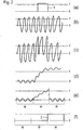
- Fig. 2 shows in a diagram (a) a transmission light pulse S, the transmitter 11 according to Fig. 1 is transmitted for a predetermined transmission pulse duration.
- Fig. 2 in diagram (b) a high-frequency interference signal, which is received from the receiver 15 in accordance with Fig. 1 received, amplified and forwarded.
- This interference signal constantly exceeds a threshold value T, so that a comparison of the received signal of the receiver 15 with this threshold value T would obviously lead to misdetections.
- FIG Fig. 2 illustrates the sum of the transmission light pulse S according to diagram (a) and the interference signal according to diagram (b).
- the sum signal falls below the threshold T even temporarily, and before and after receiving the transmitted light pulse S, the threshold T is temporarily exceeded.
- Diagram (d) according to Fig. 2 illustrates the effect of integrating the sum signal according to diagram (c).
- Diagram (s) according to Fig. 2 shows such integration of the received signal in three consecutive integration windows W.
- the signal shown thus corresponds to the output of the integrator 19 in accordance Fig. 1 .
- a threshold value T corresponding to the reception of a transmitted light pulse S is exceeded.
- Such a sequence of determined (binarized) integration values may be compared to an expected sequence of transmitted light pulses to produce a positive or negative switching signal, depending on the result of this comparison.
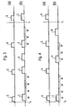
- FIG. 3 So shows Fig. 3 in a diagram (a) an expected sequence of (equidistant) transmitted light pulses S.
- diagram (b) shows Fig. 3 the actually determined received signals I after integration in the successive integration windows W and after subsequent binarization.
- the sequence of detected integration values shown also contains a noise pulse N. This is determined by comparison with the expected sequence of transmitted light pulses S according to diagram (a) of FIG Fig. 3 however identifiable as such.
- Fig. 4 also shows an expected sequence of transmitted light pulses S in diagram (a).
- diagram (b) according to FIG Fig. 4 a single binarized integration value I of a received signal is shown.
- the receiver 15 was subjected to stray light, which led to the generation of noise pulses N.
- These can be determined by correlation of the sequence shown with the pulse sequence according to diagram (a) Fig. 4 however, be detected to avoid misdetection.
- Such a correlation of determined integration values with an expected sequence of transmitted light pulses may, for example, be effected by switching from a negative to a positive switching signal only if, within a predetermined time interval (for example, time interval t 0 to t 1 in accordance with FIG 3 and 4 ) for all integration windows W, for which a transmitted light pulse S must be expected, the determined integration values I actually correspond to a received transmitted light pulse S.
- a predetermined time interval for example, time interval t 0 to t 1 in accordance with FIG 3 and 4
- a negative switching signal is retained and the determined integration values I are evaluated for an extended time interval or for a new predetermined time interval, if within the predetermined time interval (to ti) the number of integration values I, the one received transmitted light pulse S, is greater than a predetermined threshold (see diagram (b) according to Fig. 3 ).
- a predetermined threshold see diagram (b) according to Fig. 3 .
- offset elimination is achieved here by comparison with an integration window W which is not immediately adjacent to the considered integration window W.
Abstract
Description
Die vorliegende Erfindung betrifft ein Verfahren zum Synchronisieren eines Empfängers einer Lichtschranke mit einem Sender der Lichtschranke. Die Erfindung betrifft ferner eine entsprechende Lichtschranke.The present invention relates to a method for synchronizing a receiver of a light barrier with a transmitter of the light barrier. The invention further relates to a corresponding light barrier.
Eine Lichtschranke besitzt generell einen Sender, der Sendelichtpulse aussendet, zum Beispiel sichtbares oder infrarotes Licht. Die Sendelichtpulse besitzen einen bestimmten Pulsabstand zueinander und eine jeweilige Sendepulsdauer. Ein zugeordneter Empfänger empfängt diese Sendelichtpulse und erzeugt entsprechende elektrische Empfangssignale. Sofern die optische Verbindungsstrecke zwischen dem Sender und dem Empfänger durch ein Hindernis unterbrochen wird und demzufolge die Sendelichtpulse vom Empfänger nicht mehr detektiert werden können, soll dies von einer zugeordneten Auswerteeinrichtung erkannt werden können, um ein entsprechendes negatives Schaltsignal zu erzeugen.A light barrier generally has a transmitter that emits transmitted light pulses, for example, visible or infrared light. The transmitted light pulses have a specific pulse spacing from one another and a respective transmission pulse duration. An associated receiver receives these transmitted light pulses and generates corresponding electrical received signals. If the optical link between the transmitter and the receiver is interrupted by an obstacle and consequently the transmitted light pulses can no longer be detected by the receiver, this should be detected by an associated evaluation device in order to generate a corresponding negative switching signal.
Um hinsichtlich der vom Empfänger erzeugten Empfangssignale danach unterscheiden zu können, ob diese tatsächlich den Sendelichtpulsen des Senders entsprechen oder - trotz unterbrochener optischer Verbindungsstrecke - durch Störsignalpulse beispielsweise des Umgebungslichts hervorgerufen werden, müssen der Empfänger und der Sender miteinander synchronisiert werden. Besonders wichtig ist diese Synchronisierung insbesondere bei solchen Lichtschranken, bei denen der Sender und der Empfänger auf unterschiedlichen Seiten des Überwachungsbereichs in einer Gegenüberstellung angeordnet sind (Einweg-Lichtschranken) und nicht unbedingt eine elektrische Verbindung zwischen dem Pulsgenerator des Lichtsenders und der dem Empfänger zugeordneten Auswerteeinrichtung besteht.In order to be able to differentiate with regard to the received signals generated by the receiver according to whether they actually correspond to the transmit light pulses of the transmitter or - despite interrupted optical link - are caused by noise pulses, for example, the ambient light, the receiver and the transmitter must be synchronized with each other. This synchronization is particularly important in particular in the case of light barriers in which the transmitter and the receiver are arranged on opposite sides of the monitoring area in a juxtaposition (one-way light barriers) and not necessarily an electrical connection between the pulse generator the light transmitter and the evaluation device associated with the receiver consists.
Bei einer Anordnung der
Es sind einfache Synchronisationsverfahren bekannt, bei denen ein gefiltertes Empfangssignal ausgewertet wird, das oberhalb einer definierten Schwelle liegt. So genannte Zeitfenster-Verfahren überprüfen, ob innerhalb eines definierten Zeitfensters nach Empfang eines Empfangssignals, das eine definierte Schwelle überschritten hat, ein weiterer Sendelichtpuls detektiert wird. Aufwendigere Synchronisationsverfahren führen eine Differenzierung des Empfangssignals durch, um eine Pulsformanalyse vornehmen zu können. Die bekannten einfachen Synchronisationsverfahren neigen jedoch dazu, Störsignale als echte Sendelichtpulse zu interpretieren. Bei den genannten Zeitfenster-Verfahren kann ein Störsignal zu Beginn des Zeitfensters zur Desychronisation führen und somit ein unerwünschtes negatives Schaltsignal auslösen. Auch die aufwendigen Pulsformanalyse-Verfahren können zu Fehldetektionen führen, insbesondere wenn das Störsignal hohe Frequenzanteile erhält.Simple synchronization methods are known in which a filtered received signal is evaluated, which is above a defined threshold. So-called time window method check whether within a defined time window after receiving a received signal that has exceeded a defined threshold, another transmitted light pulse is detected. More elaborate synchronization methods perform a differentiation of the received signal to make a pulse shape analysis can. However, the known simple synchronization methods tend to interpret spurious signals as true transmitted light pulses. In the aforementioned time window method, an interference signal at the beginning of the time window can lead to desynchronization and thus trigger an undesired negative switching signal. Even the elaborate pulse shape analysis method can lead to misdetections, especially if the interference signal receives high frequency components.
Es ist eine Aufgabe der Erfindung, für eine Lichtschranke ein einfaches Synchronisationsverfahren mit geringer Störanfälligkeit zu schaffen.It is an object of the invention to provide a simple synchronization method with a low susceptibility to interference for a light barrier.
Diese Aufgabe wird durch ein Verfahren mit den Merkmalen des Anspruchs 1 gelöst, und insbesondere dadurch, dass die Empfangssignale in aufeinander folgenden Integrationsfenstern integriert werden, um einen jeweiligen Integrationswert zu ermitteln, wobei die ermittelten Integrationswerte mit einer erwarteten Folge von Sendelichtpulsen verglichen werden.This object is achieved by a method having the features of
Bei dem erfindungsgemäßen Synchronisationsverfahren werden die Empfangssignale also fortlaufend aufintegriert, und zwar während aufeinander folgender Integrationsfenster von vorbestimmter Länge (insbesondere konstanter Länge). Hierdurch wird im Takt der Integrationsfenster eine Folge von Integrationswerten erzeugt. Diese Folge von ermittelten Integrationswerten wird direkt oder indirekt - d.h. nach weiterer Signalverarbeitung, zum Beispiel Summenbildung - mit einer erwarteten Folge von ausgesendeten Sendelichtpulsen verglichen. Mit anderen Worten wird eine vorbestimmte Anzahl von aufeinander folgend erzeugten Integrationswerten mit einer Folge von nacheinander ausgesendeten Sendelichtpulsen korreliert, wobei diese Folge von Sendelichtpulsen empfängerseitig bekannt ist und der Auswertung der ermittelten Integrationswerte deshalb als erwarteter Wert zugrunde gelegt werden kann. In Abhängigkeit von dem Ergebnis dieses Vergleichs wird entweder ein positives Schaltsignal erzeugt, nämlich wenn eine hinreichende vorbestimmte Übereinstimmung der Folge von ermittelten Integrationswerten mit der erwarteten Folge von Sendelichtpulsen festgestellt wird, oder es wird ein negatives Schaltsignal erzeugt, nämlich wenn keine hinreichende Korrelation zwischen der ermittelten Folge von Integrationswerten und der erwarteten Folge von Sendelichtpulsen festgestellt wird.In the case of the synchronization method according to the invention, the received signals are therefore continuously integrated, specifically during successive integration windows of a predetermined length (in particular of constant length). As a result, a sequence of integration values is generated in time with the integration window. This sequence of determined integration values is directly or indirectly - i. after further signal processing, for example summation - compared with an expected sequence of transmitted transmitted light pulses. In other words, a predetermined number of successively generated integration values are correlated with a sequence of successively transmitted transmission pulses, this sequence of transmission light pulses being known on the receiver side and the evaluation of the determined integration values can therefore be used as the expected value. Depending on the result of this comparison, either a positive switching signal is generated, namely when a sufficient predetermined coincidence of the sequence of detected integration values with the expected sequence of transmitted light pulses is detected, or a negative switching signal is generated, namely if there is no sufficient correlation between the determined Sequence of integration values and the expected sequence of transmitted light pulses.
Somit wird bei diesem Verfahren zwar der vermeintliche Nachteil in Kauf genommen, dass die Information über die genaue zeitliche Lage und über die Pulsform bzw. den Pegel des Empfangssignals unterdrückt wird. Außerdem besitzt dieses Verfahren den Nachteil, dass ein empfangener Sendelichtpuls auf mehrere Integrationsfenster verteilt sein kann. Allerdings besitzt das erfindungsgemäße Synchronisationsverfahren eine verbesserte Störanfälligkeit insbesondere gegenüber hochfrequenten Störsignalen, und die ermittelten Integrationswerte bieten dennoch die Möglichkeit einer Korrelierung mit der erwarteten Folge von Sendelichtpulsen im Takt der vorbestimmten Integrationsfenster, so dass eine robuste und gleichwohl einfache Synchronisation des Empfängers auf einen externen Sender möglich ist.Thus, in this method, although the alleged disadvantage accepted that the information about the exact timing and the pulse shape or the level of the received signal is suppressed. In addition, this method has the disadvantage that a received transmission light pulse can be distributed over several integration windows. However, the synchronization method according to the invention has an improved susceptibility to interference, in particular with respect to high-frequency interference signals, and the determined integration values nevertheless offer the possibility of correlation with the expected sequence of transmitted light pulses in the cycle of predetermined integration window, so that a robust and yet easy synchronization of the receiver to an external transmitter is possible.
Die beschriebene Integration der Empfangssignale innerhalb der Integrationsfenster kann durch einen rücksetzbaren Integrator oder durch einen permanent arbeitenden Integrator mit nachfolgender Differenzbildung realisiert werden (Subtraktion des Signals zu Beginn des Integrationsfensters von dem Signal am Ende des Integrationsfensters). Der Integrator kann analog oder digital verwirklicht sein. Ein Tiefpass mit entsprechend niedriger Grenzfrequenz wirkt beispielsweise ebenfalls integrierend. Wichtig ist eine definierte zeitliche Begrenzung der Integration, um mehrere aufeinander folgende Integrationsfenster zu bilden, wobei hierunter ein Zeitintervall zu verstehen ist, während dessen das Empfangssignal aufintegriert wird.The described integration of the received signals within the integration window can be realized by a resettable integrator or by a permanently operating integrator with subsequent difference formation (subtraction of the signal at the beginning of the integration window from the signal at the end of the integration window). The integrator can be implemented analog or digital. A low pass with a correspondingly low cutoff frequency, for example, also has an integrating effect. What is important is a defined time limit of the integration in order to form a plurality of successive integration windows, this being understood to mean a time interval during which the received signal is integrated.
Gemäß einer bevorzugten Ausführungsform ist eine besonders einfache Korrelierung der ermittelten Integrationswerte mit der erwarteten Folge von Sendelichtpulsen möglich, wenn die ermittelten Integrationswerte noch vor dem Vergleich mit den erwarteten Sendelichtpulsen diskretisiert, und zwar insbesondere binarisiert werden. Hierdurch kann fortlaufend ein Bitstrom erzeugt werden, der mit der erwarteten Folge von Sendelichtpulsen auf Übereinstimmung verglichen werden kann. Mit anderen Worten werden die Integrationswerte in diesem Fall binarisiert, um im Takt der aufeinander folgenden Integrationsfenster den genannten Bitstrom zu erzeugen. Eine derartige Binarisierung der ermittelten Integrationswerte erfolgt vorzugsweise durch einen Vergleich mit wenigstens einem vorbestimmten Schwellwert.According to a preferred embodiment, a particularly simple correlation of the determined integration values with the expected sequence of transmitted light pulses is possible if the determined integration values are discretized, in particular binarized, even before the comparison with the expected transmitted light pulses. As a result, a bit stream can be generated continuously, which can be compared with the expected sequence of transmitted light pulses to match. In other words, the integration values in this case are binarized in order to generate said bitstream at the rate of the successive integration windows. Such a binarization of the determined integration values is preferably carried out by a comparison with at least one predetermined threshold value.
Alternativ hierzu können die ermittelten Integrationswerte jedoch auch in analoger Form mit den erwarteten Sendelichtpulsen korreliert werden.Alternatively, however, the determined integration values can also be correlated in analogous form with the expected transmitted light pulses.
Für den erläuterten Vergleich der ermittelten Integrationswerte mit der erwarteten Folge von Sendelichtpulsen wird vorzugsweise eine ausgewählte Folge von ermittelten Integrationswerten relativ zu der erwarteten Folge von Sendelichtpulsen um eine oder mehrere verschiedene Zeitabstände versetzt, um einen jeweiligen Übereinstimmungsgrad zwischen den beiden Folgen zu bestimmen und um hierbei eine eventuelle Phasendifferenz zwischen den beiden Folgen zu kompensieren. Hierbei kann beispielsweise der höchste ermittelte Übereinstimmungsgrad für die weitere Auswertung berücksichtigt werden.For the explained comparison of the determined integration values with the expected sequence of transmitted light pulses, preferably a selected sequence of determined integration values relative to the expected sequence of transmitted light pulses is offset by one or more different time intervals to determine a respective degree of agreement between the two sequences and thereby one compensate for any phase difference between the two sequences. In this case, for example, the highest determined degree of agreement can be taken into account for further evaluation.
Weiterhin ist es bevorzugt, wenn die Auswertung der ermittelten Integrationswerte dahingehend erfolgt, dass ein positives Schaltsignal erzeugt wird, falls der Vergleich der ermittelten Integrationswerte mit der erwarteten Folge von Sendelichtpulsen eine vorbestimmte Mindestübereinstimmung ergibt. Beispielsweise kann ein positives Schaltsignal (Synchronisation EIN) festgestellt werden, wenn innerhalb eines vorbestimmten Zeitintervalls für jedes Integrationsfenster, für das ein Sendelichtpuls erwartet wird, der tatsächlich ermittelte Integrationswert auch einem empfangenen Sendelichtpuls entspricht, wobei andernfalls ein negatives Schaltsignal erzeugt wird (Synchronisation AUS). Das betrachtete vorbestimmte Zeitintervall beträgt vorzugsweise ein Vielfaches des Pulsabstands zwischen zwei aufeinander folgenden Sendelichtpulsen.Furthermore, it is preferred if the evaluation of the determined integration values takes place in such a way that a positive switching signal is generated if the comparison of the determined integration values with the expected sequence of transmitted light pulses results in a predetermined minimum match. For example, a positive switching signal (synchronization ON) can be detected if, within a predetermined time interval for each integration window for which a transmission light pulse is expected, the actually determined integration value also corresponds to a received transmission light pulse, otherwise a negative switching signal is generated (synchronization OFF). The considered predetermined time interval is preferably a multiple of the pulse interval between two successive transmitted light pulses.
Um eine besonders geringe Störanfälligkeit zu erreichen, ist es bevorzugt, wenn die Umschaltregeln für das Umschalten zwischen einem positiven und einem negativen Schaltsignal in Abhängigkeit von dem aktuellen Schaltzustand gewählt werden. Mit anderen Worten sollen in dem Fall, dass bereits ein positives Schaltsignal vorliegt, für das Beibehalten des positiven Schaltsignals andere Kriterien berücksichtigt werden als für ein Umschalten von einem negativen Schaltsignal auf ein positives Schaltsignal. Umgekehrt können auch in dem Fall, dass bereits ein negatives Schaltsignal vorliegt, für das Beibehalten dieses negativen Schaltsignals andere Kriterien berücksichtigt werden als für ein Umschalten von einem positiven Schaltsignal auf ein negatives Schaltsignal. Beispielsweise können je nach aktuellem Schaltzustand unterschiedliche Schwellwerte zur Bewertung des Korrelationsergebnisses herangezogen werden, zum Beispiel eine unterschiedliche Anzahl von Integrationswerten innerhalb eines vorbestimmten Zeitintervalls, die einem erwarteten Sendelichtpuls entsprechen müssen. Beispielsweise können auch für die erläuterte Binarisierung der Integrationswerte in Abhängigkeit von dem aktuellen Schaltzustand unterschiedliche Schwellwerte berücksichtigt werden.In order to achieve a particularly low susceptibility to interference, it is preferred if the switching rules for the switching between a positive and a negative switching signal are selected as a function of the current switching state. In other words, in that case that a positive switching signal is already present, for the maintenance of the positive switching signal other criteria are taken into account than for switching from a negative switching signal to a positive switching signal. Conversely, even in the event that there is already a negative switching signal, for the maintenance of this negative switching signal other criteria can be considered as for switching from a positive switching signal to a negative switching signal. For example, depending on the current switching state, different threshold values can be used to evaluate the correlation result, for example a different number of integration values within a predetermined time interval, which must correspond to an expected transmitted light pulse. For example, different threshold values can also be taken into account for the described binarization of the integration values as a function of the current switching state.
Was die jeweilige Dauer der aufeinander folgenden Integrationsfenster betrifft, so entspricht diese vorzugsweise ungefähr der Sendepulsdauer der ausgesendeten Sendelichtpulse, wobei die Dauer eines Integrationsfensters beispielsweise einen Wert zwischen einem Viertel bis zu dem 4-fachen der Sendepulsdauer besitzen kann. Besonders vorteilhafte Möglichkeiten zur Auswertung der ermittelten Integrationswerte bestehen, wenn die Dauer eines Integrationsfensters der Hälfte der Sendepulsdauer, genau der Sendepulsdauer oder der doppelten Sendepulsdauer entspricht. Sofern die Dauer eines Integrationsfensters ungefähr der Sendepulsdauer entspricht, können die aufintegrierten Empfangssignale durch Diskretisierung nach Zeit und/oder Amplitude besonders gut mit den entsprechenden Sendelichtpulsen korreliert werden.As far as the respective duration of the successive integration windows is concerned, this preferably corresponds approximately to the transmission pulse duration of the emitted transmitted light pulses, wherein the duration of an integration window may, for example, have a value between one quarter to four times the transmission pulse duration. Particularly advantageous possibilities for evaluating the determined integration values exist if the duration of an integration window corresponds to half the transmission pulse duration, exactly the transmission pulse duration or the double transmission pulse duration. If the duration of an integration window corresponds approximately to the transmission pulse duration, the integrated received signals can be correlated particularly well with the corresponding transmitted light pulses by discretization according to time and / or amplitude.
Ferner ist es bevorzugt, wenn die Frequenz, mit der die aufeinander folgenden Integrationsfenster erzeugt werden, einem ganzzahligen Vielfachen der Aussendefrequenz der Sendelichtpulse entspricht. Mit anderen Worten soll die Dauer eines Integrationsfensters einen ganzzahligen Bruchteil des Pulsabstands der Sendelichtpulse betragen. Hierdurch vereinfacht sich die Auswertung, da zwischen der Folge von Sendelichtpulsen und den ermittelten Integrationswerten generell lediglich eine Phasenverschiebung vorliegen kann. Da diese Phasenverschiebung sich durch Drifteffekte gleichwohl allmählich ändern kann, ist es jedoch bevorzugt, wenn das erläuterte Synchronisieren des Empfängers mit dem Empfänger während der gesamten Dauer eines Überwachungsbetriebs der Lichtschranke fortgesetzt wird.Furthermore, it is preferred if the frequency with which the successive integration windows are generated is an integer multiple the transmission frequency of the transmitted light pulses corresponds. In other words, the duration of an integration window should be an integer fraction of the pulse interval of the transmitted light pulses. This simplifies the evaluation, since generally only one phase shift can exist between the sequence of transmitted light pulses and the determined integration values. However, since this phase shift may gradually change due to drift effects, however, it is preferred that the described synchronization of the receiver with the receiver be continued throughout the duration of a monitor operation of the light barrier.
Alternativ zu der vorgenannten vereinfachten Frequenzwahl ist es auch möglich, dass die Sendelichtpulse nicht äquidistant, sondern in unterschiedlichen Pulsabständen gesendet werden. Sofern das diesbezügliche Sendemuster der empfängerseitigen Auswerteeinrichtung bekannt ist, können die ermittelten Integrationswerte gleichwohl mit einer erwarteten Folge von Sendelichtpulsen korreliert werden, wobei eine verbesserte Störanfälligkeit gegenüber Störquellen mit konstanter Sendefrequenz erzielt wird.As an alternative to the aforementioned simplified frequency selection, it is also possible that the transmitted light pulses are not sent equidistantly, but at different pulse intervals. If the relevant transmission pattern of the receiver-side evaluation device is known, the determined integration values can nevertheless be correlated with an expected sequence of transmitted light pulses, whereby an improved susceptibility to interference with sources of interference with a constant transmission frequency is achieved.
Die Erfindung bezieht sich auch auf eine Lichtschranke, die zur Durchführung des erfindungsgemäßen Verfahrens ausgebildet ist und insbesondere eine Integriereinrichtung aufweist, durch die die Empfangssignale in aufeinander folgenden Integrationsfenstern integrierbar sind, um einen jeweiligen Integrationswert zu ermitteln, und die ferner eine Auswerteeinrichtung aufweist, durch die die ermittelten Integrationswerte mit einer erwarteten Folge von Sendelichtpulsen verglichen werden.The invention also relates to a light barrier, which is designed to carry out the method according to the invention and in particular has an integrating device, by which the received signals can be integrated in successive integration windows to determine a respective integration value, and further comprising an evaluation device, through which the determined integration values are compared with an expected sequence of transmitted light pulses.
Weitere Ausführungsformen der Erfindung sind in den Unteransprüchen genannt.Further embodiments of the invention are mentioned in the subclaims.
Die Erfindung wird nachfolgend lediglich beispielhaft unter Bezugnahme auf die Zeichnungen erläutert.
- Fig. 1
- zeigt ein Blockschaltbild einer Lichtschranke.
- Fig. 2
- zeigt verschiedene Signalverläufe.
- Fig. 3 und 4
- zeigen verschiedene Folgen von Sendelichtpulsen und zugehörigen Integrationswerten.
- Fig. 1
- shows a block diagram of a light barrier.
- Fig. 2
- shows different waveforms.
- 3 and 4
- show different sequences of transmitted light pulses and associated integration values.
Die derartig gefilterten Empfangssignale werden einem Integrator 19 zugeführt. Dieser integriert die Empfangssignale in kontinuierlich erzeugten aufeinander folgenden Integrationsfenstern von bestimmter Dauer auf, um einen jeweiligen Integrationswert zu erzeugen. Eine derartige Integration kann beispielsweise in analoger Form mittels eines Kondensators erfolgen. Wichtig ist, dass die Integration zeitlich getaktet erfolgt, um die Empfangssignale unterteilt nach aufeinander folgenden Zeitintervallen aufzuintegrieren. Hierfür kann der Integrator 19 beispielsweise an einen Taktgeber angeschlossen sein (nicht gezeigt), der für ein regelmäßiges Rücksetzen des Integrators 19 sorgt.The received signals filtered in this way are supplied to an
Die somit ermittelten Integrationswerte werden nachfolgend diskretisiert. Hierfür ist in dem gezeigten Beispiel dem Integrator 19 ein Schwellwertschalter 21 nachgeschaltet, der eine Binarisierung der Integrationswerte bewirkt, indem die Integrationswerte mit einem vorbestimmten Schwellwert verglichen werden. An seinem Ausgang liefert der Schwellwertschalter 21 demzufolge bei Überschreiten oder Unterschreiten des Schwellwerts das Signal EINS bzw. NULL. Somit wird am Ausgang des Schwellwertschalters 21 im Takt der Integrationsfenster des Integrators 19 ein Bitstrom erzeugt. Anstelle einer derartigen Binarisierung ist auch eine Analog/ Digital-Wandlung möglich, also eine Umwandlung der Integrationswerte in mehr als zwei diskrete Ausgangswerte.The thus determined integration values are subsequently discretized. For this purpose, in the example shown, the
Dieser Bitstrom wird einer nachgeschalteten Auswerteeinrichtung 23 zugeführt, die in digitaler Ausgestaltung beispielsweise durch einen Mikroprozessor gebildet sein kann, wobei grundsätzlich auch eine analoge Ausführung möglich ist. Die Auswerteeinrichtung 23 korreliert die ermittelten Integrationswerte in der erläuterten binarisierten Form mit einer Signalfolge, die aufgrund der bekannten Ansteuerung des Senders 11 bei ungestörtem Empfang und freier optischer Verbindungsstrecke 13 erwartet wird. In Abhängigkeit von dem Ergebnis dieses Vergleichs erzeugt die Auswerteeinrichtung 23 an einem Schaltausgang 25 entweder ein positives Schaltsignal oder ein negatives Schaltsignal.This bit stream is fed to a
Die in
Beispielsweise muss vermieden werden, dass trotz des Vorhandenseins eines Hindernisses 31 entlang der optischen Verbindungsstrecke 13 ein optisches Signal einer intermittierend abstrahlenden Störlichtquelle 33 mit einem Sendelichtpuls des Senders 11 verwechselt wird und somit fälschlicherweise von einem freien Überwachungsbereich ausgegangen wird. Um derartige Effekte zu vermeiden, ist es erforderlich, den Empfänger 15 bzw. die zugeordnete Auswerteeinrichtung 23 mit dem Sender 11 zu synchronisieren, d.h. die Empfangssignale des Empfängers 15 müssen "echten" Sendelichtpulsen des Senders 11 zuverlässig zugeordnet und von Störlichtsignalen unterschieden werden können.For example, it must be avoided that, in spite of the presence of an
Zu diesem Zweck werden die Empfangssignale des Empfängers 15, wie bereits erläutert, gemäß aufeinander folgenden Integrationsfenstern konstanter Länge aufintegriert, nachfolgend binarisiert und anschließend - in Form eines Bitstroms - mit einer erwarteten Folge von empfangenen Sendelichtpulsen verglichen, wobei auch an sich bekannte Korrelierungsverfahren zur Anwendung gelangen können. Generell wird an dem Schaltausgang 25 der Auswerteeinrichtung 23 ein positives Schaltsignal ausgegeben, wenn dieser Vergleich eine vorbestimmte Mindestübereinstimmung zwischen den ermittelten Integrationswerten einerseits und der erwarteten (bekannten) Folge von Sendelichtpulsen andererseits ergibt, wobei im Falle eines negativen Prüfergebnisses ein negatives Schaltsignal ausgegeben wird.For this purpose, the received signals of the
Nachfolgend soll anhand von
Ferner zeigt
Dieses Problem zeigt sich insbesondere aufgrund des Diagramms (c) gemäß
Diagramm (d) gemäß
Falls eine derartige Integration in aufeinander folgenden Integrationsfenstern von geeigneter Länge durchgeführt wird, können die vorstehend erläuterten nachteiligen Effekte eines hochfrequenten Störsignals vermieden werden. Diagramm (e) gemäß
Sofern die für die einzelnen Integrationsfenster W ermittelten Integrationswerte I durch Vergleich mit dem Schwellwert T binarisiert werden (Ausgangssignal des Schwellwertschalters 21 gemäß
Eine derartige Folge von ermittelten (binarisierten) Integrationswerten kann mit einer erwarteten Folge von Sendelichtpulsen verglichen werden, um in Abhängigkeit von dem Ergebnis dieses Vergleichs ein positives oder negatives Schaltsignal zu erzeugen.Such a sequence of determined (binarized) integration values may be compared to an expected sequence of transmitted light pulses to produce a positive or negative switching signal, depending on the result of this comparison.
So zeigt
Eine derartige Korrelierung von ermittelten Integrationswerten mit einer erwarteten Folge von Sendelichtpulsen kann beispielsweise dahingehend erfolgen, dass nur dann von einem negativen zu einem positiven Schaltsignal umgeschaltet wird, wenn innerhalb eines vorbestimmten Zeitintervalls (zum Beispiel Zeitintervall t0 bis t1 gemäß
Weiterhin kann zur Auswertung eines erzeugten Bitstroms vorgesehen sein, dass nur dann von einem positiven zu einem negativen Schaltsignal umgeschaltet wird, wenn innerhalb eines vorbestimmten Zeitintervalls (zum Beispiel t0 bis t1) für kein einziges Integrationsfenster W, für das ein Sendelichtpuls S erwartet wird, der tatsächlich ermittelte Integrationswert 1 einem empfangenen Sendelichtpuls S entspricht. Hierdurch wird ein zu frühes Umschalten auf ein negatives Schaltsignal vermieden.Furthermore, to evaluate a generated bit stream, it is possible to switch from a positive to a negative switching signal only if within a predetermined time interval (for example, t 0 to t 1 ) for no single integration window W for which a transmitted light pulse S is expected , the actually determined
Bezüglich der Dauer eines Integrationsfensters W relativ zu der Sendepulsdauer der Sendelichtpulse S bestehen beispielsweise die folgenden Möglichkeiten:
- (1) Die Dauer eines Integrationsfensters W kann beispielsweise um einen Faktor i größer sein als die Sendepulsdauer, wobei in diesem Fall die Empfangssignale in mehreren, nämlich i Folgen von aufeinander folgenden Integrationsfenstern W integriert werden, und wobei diese i Folgen um einen Bruchteil 1/i der Dauer eines Integrationsfensters W zueinander versetzt sind. Mit anderen Worten würden bei dieser Variante mehrere Auswertungen parallel erfolgen. Der Vorteil dieser Variante besteht darin, dass unabhängig von der Phasenlage der Integrationsfenster W der empfangene Sendelichtpuls zumindest in einer der mehreren Auswertungen vollständig innerhalb eines Integrationsfensters W aufintegriert wird.
Vorzugsweise wird als Faktor i = 2 gewählt, d.h. die Dauer eines Integrationsfensters W entspricht ungefähr der doppelten Sendepulsdauer, und die Empfangssignale werden in zwei Folgen von Integrationsfenstern W aufintegriert, die um die Hälfte der Dauer eines Integrationsfensters W zueinander versetzt sind. Die hieraus resultierenden zwei parallel erzeugten Bitströme können entweder unabhängig voneinander, d.h. parallel zueinander jeweils mit der erwarteten Folge von Sendelichtpulsen S korreliert werden, oder diese beiden Bitströme werden erst zu einem einzigen Bitstrom zusammengefasst und anschließend mit der erwarteten Folge von Sendelichtpulsen S korreliert. - (2) Alternativ hierzu kann die Dauer eines Integrationsfensters W ungefähr der Sendepulsdauer entsprechen, wobei bei dieser Variante die Integrationswerte I von zwei jeweils, aufeinander folgenden Integrationsfenstern W addiert werden, um eine Summenwertfolge (Bitstrom) zu bilden, die mit der erwarteten Folge von Sendelichtpulsen S verglichen wird (zum Beispiel I1 + I2, dann I2 + I3, dann I3 + I4 etc.). Auch hierdurch wird erreicht, dass innerhalb der gebildeten Summenwertfolge ein erfasster Sendelichtpuls stets vollständig enthalten ist. Vorzugsweise erfolgt ein Schwellwertvergleich hier für jeden gebildeten Summenwert (d.h. nach der erfolgten Summenwertbildung), um hierdurch einen Bitstrom zu erzeugen.
Fehler der realen Integration (zum Beispiel Offsetfehler des Integrators) können dazu führen, dass in jedem Integrationsfenster W ein konstanter Offset vorhanden ist. Daher ist es für diese und auch für die vorgenannte Variante (1) bevorzugt, wenn das Integrationsergebnis mit dem Integrationsergebnis anderer Fenster W, die kein Signal eines Sendelichtpulses S enthalten, verglichen wird. Dies wird insbesondere dadurch realisiert, dass von dem Integrationsergebnis der Integrationswert I des vorherigen und/oder des nachfolgenden Integrationsfensters W subtrahiert wird. - (3) Außerdem ist es beispielsweise möglich, dass die Dauer eines Integrationsfensters W lediglich einem Bruchteil 1/m der Sendepulsdauer entspricht, wobei für m vorzugsweise ein ganzzahliger positiver Wert gewählt wird. Insbesondere beträgt die Dauer eines Integrationsfensters W ungefähr die Hälfte der Sendepulsdauer. Hierdurch ist stets ein Integrationsfenster W vorhanden, für dessen gesamte Dauer das Signal eines empfangenen Sendelichtpulses vorhanden ist. Somit ist auch hier eine Schwankung des ermittelten Integrationswerts in Abhängigkeit von der Sendephase nicht vorhanden.
- (1) The duration of an integration window W may, for example, be greater than the transmission pulse duration by a factor i, in which case the received signals are integrated into a plurality of, namely i, sequences of successive integration windows W, and these sequences are separated by a
fraction 1 / i are the duration of an integration window W offset from each other. In other words, in this variant, several evaluations would take place in parallel. The advantage of this variant is that regardless of the phase position of the integration window W, the received transmitted light pulse is integrated completely within an integration window W at least in one of the several evaluations.
Preferably, the factor i = 2 is selected, ie the duration of an integration window W corresponds to approximately twice the transmission pulse duration, and the reception signals are integrated into two sequences of integration windows W offset by half the duration of an integration window W relative to one another. The resulting two parallel generated bitstreams can be correlated either independently, ie, parallel to each other with the expected sequence of transmitted light pulses S, or these two bitstreams are first combined into a single bitstream and then correlated with the expected sequence of transmitted light pulses S. - (2) Alternatively, the duration of an integration window W may correspond approximately to the transmit pulse duration, in which variant the integration values I of two successive integration windows W are added to form a cumulative sequence (bitstream) corresponding to the expected sequence of transmit light pulses S is compared (for example, I 1 + I 2 , then I 2 + I 3 , then I 3 + I 4, etc.). This also ensures that within the formed sum value sequence a detected transmitted light pulse is always completely contained. A threshold value comparison is preferably carried out here for each summation value formed (ie after the summation value has been established), in order thereby to generate a bit stream.
Errors of the real integration (for example offset errors of the integrator) can lead to a constant offset being present in each integration window W. Therefore, it is preferable for this and also for the aforementioned variant (1) if the integration result is compared with the integration result of other windows W which do not contain a signal of a transmitted light pulse S. This is realized in particular by subtracting from the integration result the integration value I of the previous and / or the following integration window W. - (3) In addition, it is possible, for example, for the duration of an integration window W to correspond to only a
fractional part 1 / m of the transmission pulse duration, wherein m is preferably chosen to be an integer positive value. In particular, the duration of an integration window W is approximately half the transmission pulse duration. As a result, an integration window W is always present, for the entire duration of which the signal of a received transmitted light pulse is present. Thus, a fluctuation of the determined integration value as a function of the transmission phase is also not present here.
Anders als bei den Varianten (1) und (2) wird eine Offseteliminierung hier durch einen Vergleich mit einem Integrationsfenster W erreicht, das nicht unmittelbar benachbart zu dem betrachteten Integrationsfenster W liegt.Unlike variants (1) and (2), offset elimination is achieved here by comparison with an integration window W which is not immediately adjacent to the considered integration window W.
- 1111
- Sendertransmitter
- 1313
- optische Verbindungsstreckeoptical link
- 1515
- Empfängerreceiver
- 1717
- Hochpasshighpass
- 1919
- Integratorintegrator
- 2121
- SchwellschwertschalterSchwellschwertschalter
- 2323
- Auswerteeinrichtungevaluation
- 2525
- Schaltausgangswitching output
- 3131
- Hindernisobstacle
- 3333
- Störlichtquelleinterference light source
- II
- binarisierter Integrationswert eines Empfangssignalsbinarized integration value of a received signal
- NN
- StörsignalpulsStörsignalpuls
- SS
- SendesignalpulsTransmit signal pulse
- TT
- Schwellwertthreshold
- t0 bis t1 t 0 to t 1
- Zeitintervalltime interval
- WW
- Integrationsfensterintegration window
Claims (20)
- A method for the synchronisation of a receiver (15) of a light barrier with a transmitter (11) of the light barrier, wherein the transmitter (11) transmits transmitted light pulses and the receiver (15) receives the transmitted light pulses and generates corresponding electrical received signals,
characterised in that
the received signals are integrated in mutually following integration windows (W) to determine a respective integration value (I), with a sequence of the determined integration values being compared with an expected sequence of transmitted light pulses. - A method in accordance with claim 1, characterised in that a positive or a negative switching signal is generated in dependence on the result of the comparison of the sequence of the determined integration values with the expected sequence of transmitted light pulses.
- A method in accordance with one of the preceding claims, characterised in that the determined integration values (I) are discretised before the comparison with the expected sequence of transmitted light pulses.
- A method in accordance with any one of the preceding claims, characterised in that the determined integration values (I) are binarised by a comparison with a threshold value (T).
- A method in accordance with any one of the preceding claims, characterised in that, for the comparison of the sequence of the determined integration values with the expected sequence of transmitted light pulses, this sequence of determined integration values is displaced relative to the expected sequence of transmitted light pulses to determine a respective degree of coincidence.
- A method in accordance with any one of the preceding claims, characterised in that a positive switching signal is generated in the event that the comparison of the sequence of the determined integration values with the expected sequence of transmitted light pulses produces a preset minimum coincidence and otherwise a negative switching signal is generated.
- A method in accordance with any one of the preceding claims, characterised in that a switch is only made from a negative switching signal to a positive switching signal when the determined integration values (I) correspond to a received transmitted light pulse within a preset time interval (to to t1) for all integration windows (W) for which a transmitted light pulse is expected, wherein, however, in the event that the number of integration values which correspond to a received transmitted light pulse is larger than a threshold value within the preset time interval, the negative switching signal is maintained and the determined integration values are evaluated for an extended time interval or for a new preset time interval.
- A method in accordance with any one of the preceding claims, characterised in that a switch is only made from a positive switching signal to a negative switching signal when within a predetermined time interval (to to t1) the determined integration value does not correspond to a received transmitted light pulse for any single integration window (W) for which a transmitted light pulse is expected.
- A method in accordance with any one of the preceding claims, characterised in that, in the event that a positive switching signal is already present, a different rule is taken into account for the maintenance of the positive switching signal than for a switching from a negative switching signal to a positive switching signal.
- A method in accordance with any one of the preceding claims, characterised in that, in the event that a negative switching signal is already present, a different rule is taken into account for the maintenance of the negative switching signal than for a switching from a positive switching signal to a negative switching signal.
- A method in accordance with any one of the preceding claims, characterised in that the respective duration of the integration windows (W) approximately corresponds to the transmitted pulse duration, with the duration of an integration window in particular corresponding to a value from a range from one quarter up to four times the transmitted pulse duration.
- A method in accordance with any one of the preceding claims, characterised in that the duration of an integration window (W) of the transmitted pulse duration corresponds to half the transmitted pulse duration or twice the transmitted pulse duration.
- A method in accordance with any one of the preceding claims, characterised in that the duration of an integration window (W) approximately corresponds to the transmitted pulse duration multiplied by a whole number factor i, with the received signals being integrated in i sequences of integration windows following one another, with the i sequences being offset with respect to one another by a fraction 1 / i of the duration of an integration window, and where preferably i = 2.
- A method in accordance with any one of the claims 1 to 12, characterised in that the duration of an integration window (W) corresponds to the transmitted pulse duration, with the integration values of at least two respective mutually following integration values being added to form a sum value sequence with reference to the integration values (I) which is compared with the expected sequence of transmitted light pulses.
- A method in accordance with any one of the claims 1 to 12, characterised in that the duration of an integration window (W) approximately corresponds to a whole number fraction 1/m of the transmitted light duration.
- A method in accordance with any one of the preceding claims, characterised in that the frequency with which the mutually following integration windows (W) are generated corresponds to a whole number multiple of the transmission frequency of the transmitted light pulses.
- A method in accordance with any one of the preceding claims, characterised in that the received signals are high pass filtered before the integration.
- A method in accordance with any one of the preceding claims, characterised in that the synchronisation of the receiver (15) with the transmitter (11) takes place during the whole duration of a monitoring operation of the light barrier.
- A light barrier, in particular for the carrying out of the method in accordance with any one of the preceding claims, comprising:- at least one transmitter (11) for the transmission of transmitted light pulses; and- a receiver (15) for the reception of the transmitted light pulses and for the generation of corresponding electrical received signals,characterised by- an integration device (19) by which the received signals can be integrated in mutually following integration windows (W) to determine a respective integration value (I); and- an evaluation device (23) by which the sequence of the determined integration values can be compared with an expected sequence of transmitted light pulses.
- A light barrier in accordance with claim 19, characterised by a comparator (21) by which the determined integration values can be compared with a threshold value before the comparison with the expected sequence of transmitted light pulses to binarise the determined integration values.
Applications Claiming Priority (1)
| Application Number | Priority Date | Filing Date | Title |
|---|---|---|---|
| DE102006016027A DE102006016027A1 (en) | 2006-04-05 | 2006-04-05 | Synchronization method for a light barrier |
Publications (2)
| Publication Number | Publication Date |
|---|---|
| EP1843175A1 EP1843175A1 (en) | 2007-10-10 |
| EP1843175B1 true EP1843175B1 (en) | 2010-01-20 |
Family
ID=38158002
Family Applications (1)
| Application Number | Title | Priority Date | Filing Date |
|---|---|---|---|
| EP07005821A Active EP1843175B1 (en) | 2006-04-05 | 2007-03-21 | Synchronisation method for a light barrier and corresponding light barrier |
Country Status (3)
| Country | Link |
|---|---|
| EP (1) | EP1843175B1 (en) |
| AT (1) | ATE456069T1 (en) |
| DE (2) | DE102006016027A1 (en) |
Cited By (1)
| Publication number | Priority date | Publication date | Assignee | Title |
|---|---|---|---|---|
| EP3460533A1 (en) | 2017-09-21 | 2019-03-27 | Sick AG | Optoelectronic sensor and method for detecting transparent objects |
Families Citing this family (1)
| Publication number | Priority date | Publication date | Assignee | Title |
|---|---|---|---|---|
| US9641259B1 (en) * | 2016-06-20 | 2017-05-02 | Rockwell Automation Technologies, Inc. | System and method for pulsed based receiver photo sensor |
Family Cites Families (12)
| Publication number | Priority date | Publication date | Assignee | Title |
|---|---|---|---|---|
| DE4141468C2 (en) * | 1991-12-16 | 1994-06-30 | Sick Optik Elektronik Erwin | Optical sensor arrangement and method for its operation |
| DE4323910C2 (en) | 1993-07-16 | 1995-08-10 | Leuze Electronic Gmbh & Co | Photoelectric sensor with evaluation electronics for the detection of interference signals |
| US5532472A (en) * | 1994-11-15 | 1996-07-02 | Sunx Kabushiki Kaisha | Photoelectric switch monitoring the duration of pulsed light to prevent false signals due to ambient conditions |
| DE19525057C1 (en) * | 1995-07-10 | 1997-02-13 | Futronic Gmbh | Light barrier device and method for processing a light sensor output signal |
| DE19720176C1 (en) * | 1996-04-06 | 1999-02-25 | Leuze Electronic Gmbh & Co | Fault signal elimination method for light barrier |
| DE19832673C2 (en) * | 1997-07-23 | 2003-03-06 | Leuze Electronic Gmbh & Co | Optical light scanner |
| DE19924351C2 (en) * | 1998-06-05 | 2003-07-24 | Leuze Electronic Gmbh & Co | Photoelectric barrier |
| DE20003675U1 (en) * | 1999-03-02 | 2000-06-08 | Leuze Electronic Gmbh & Co | Optoelectronic device |
| DE29923142U1 (en) * | 1999-06-30 | 2000-04-13 | Leuze Electronic Gmbh & Co | Sensitivity control for light sensors |
| DE10117838A1 (en) * | 2001-04-02 | 2002-10-17 | Omron Electronics Mfg Of Germa | Interference light suppression method and measuring device |
| DE10210340A1 (en) * | 2002-03-08 | 2003-09-18 | Leuze Electronic Gmbh & Co | Optoelectronic device for measuring the distance to an object using triangulation principles has the same circuit for calculation of both sum and difference voltages and ensures the difference voltage is drift independent |
| DE10341008A1 (en) * | 2003-09-05 | 2005-03-31 | Leuze Electronic Gmbh & Co Kg | Optoelectronic device |
-
2006
- 2006-04-05 DE DE102006016027A patent/DE102006016027A1/en not_active Withdrawn
-
2007
- 2007-03-21 DE DE502007002650T patent/DE502007002650D1/en active Active
- 2007-03-21 AT AT07005821T patent/ATE456069T1/en active
- 2007-03-21 EP EP07005821A patent/EP1843175B1/en active Active
Cited By (2)
| Publication number | Priority date | Publication date | Assignee | Title |
|---|---|---|---|---|
| EP3460533A1 (en) | 2017-09-21 | 2019-03-27 | Sick AG | Optoelectronic sensor and method for detecting transparent objects |
| US10921483B2 (en) | 2017-09-21 | 2021-02-16 | Sick Ag | Optoelectronic sensor and method for detecting transparent objects |
Also Published As
| Publication number | Publication date |
|---|---|
| DE502007002650D1 (en) | 2010-03-11 |
| DE102006016027A1 (en) | 2007-10-11 |
| EP1843175A1 (en) | 2007-10-10 |
| ATE456069T1 (en) | 2010-02-15 |
Similar Documents
| Publication | Publication Date | Title |
|---|---|---|
| DE19611195C1 (en) | Operating light barrier with at least two synchronously operated transmitter/receiver pairs | |
| DE4141468C2 (en) | Optical sensor arrangement and method for its operation | |
| DE3601516C2 (en) | ||
| DE102008009180A1 (en) | Optoelectronic sensor | |
| EP0048047B1 (en) | Apparatus for the recognition of a binary word | |
| DE4141469C2 (en) | Method for operating an optical sensor arrangement for the detection of objects present in a monitoring area, and such an optical sensor arrangement | |
| EP2071363A2 (en) | Lighting grid and method for its operation | |
| DE4224784C2 (en) | Process for operating light barriers, light grids or light curtains | |
| DE10211387B4 (en) | Sensor using radiation pulses | |
| EP0768545B1 (en) | Method for operating a light sensor | |
| EP1853942B1 (en) | Method for operating an optoelectronic sensor | |
| EP1843175B1 (en) | Synchronisation method for a light barrier and corresponding light barrier | |
| EP1933173A1 (en) | Light grid | |
| EP3244237B1 (en) | Optical sensor and method of operating an optical sensor | |
| EP2983009B1 (en) | Operation of an optoelectronic sensor using a method for emitting light pulses | |
| DE19926214A1 (en) | Suppression of noise signals in signal from optical sensor or proximity switch by transmitting chirp sequence and autocorrelating | |
| EP2278360B1 (en) | Method for operating an optical sensor | |
| DE202008014137U1 (en) | light curtain | |
| DE19613940C2 (en) | Procedure for eliminating interference signals from a light barrier | |
| DE2939139C2 (en) | ||
| EP0772788B1 (en) | Process and device for eliminating interference signals in a light barrier | |
| EP2490045B1 (en) | Optoelectronic sensor and method for detecting objects | |
| DE19833353C2 (en) | light sensor | |
| DE102008022791A1 (en) | Light grid for detection of objects in monitoring area, has multiple radiation axes, where light rays emitted by transmitter are guided to assigned receiver through monitoring area in free monitoring area along each radiation axis | |
| DE19924733A1 (en) | Device for reading or writing to optical recording media |
Legal Events
| Date | Code | Title | Description |
|---|---|---|---|
| PUAI | Public reference made under article 153(3) epc to a published international application that has entered the european phase |
Free format text: ORIGINAL CODE: 0009012 |
|
| AK | Designated contracting states |
Kind code of ref document: A1 Designated state(s): AT BE BG CH CY CZ DE DK EE ES FI FR GB GR HU IE IS IT LI LT LU LV MC MT NL PL PT RO SE SI SK TR |
|
| AX | Request for extension of the european patent |
Extension state: AL BA HR MK YU |
|
| 17P | Request for examination filed |
Effective date: 20080201 |
|
| AKX | Designation fees paid |
Designated state(s): AT BE BG CH CY CZ DE DK EE ES FI FR GB GR HU IE IS IT LI LT LU LV MC MT NL PL PT RO SE SI SK TR |
|
| GRAP | Despatch of communication of intention to grant a patent |
Free format text: ORIGINAL CODE: EPIDOSNIGR1 |
|
| GRAS | Grant fee paid |
Free format text: ORIGINAL CODE: EPIDOSNIGR3 |
|
| GRAA | (expected) grant |
Free format text: ORIGINAL CODE: 0009210 |
|
| AK | Designated contracting states |
Kind code of ref document: B1 Designated state(s): AT BE BG CH CY CZ DE DK EE ES FI FR GB GR HU IE IS IT LI LT LU LV MC MT NL PL PT RO SE SI SK TR |
|
| REG | Reference to a national code |
Ref country code: GB Ref legal event code: FG4D Free format text: NOT ENGLISH |
|
| REG | Reference to a national code |
Ref country code: CH Ref legal event code: EP |
|
| REG | Reference to a national code |
Ref country code: IE Ref legal event code: FG4D |
|
| REF | Corresponds to: |
Ref document number: 502007002650 Country of ref document: DE Date of ref document: 20100311 Kind code of ref document: P |
|
| REG | Reference to a national code |
Ref country code: NL Ref legal event code: T3 |
|
| LTIE | Lt: invalidation of european patent or patent extension |
Effective date: 20100120 |
|
| PG25 | Lapsed in a contracting state [announced via postgrant information from national office to epo] |
Ref country code: ES Free format text: LAPSE BECAUSE OF FAILURE TO SUBMIT A TRANSLATION OF THE DESCRIPTION OR TO PAY THE FEE WITHIN THE PRESCRIBED TIME-LIMIT Effective date: 20100501 Ref country code: LT Free format text: LAPSE BECAUSE OF FAILURE TO SUBMIT A TRANSLATION OF THE DESCRIPTION OR TO PAY THE FEE WITHIN THE PRESCRIBED TIME-LIMIT Effective date: 20100120 Ref country code: IS Free format text: LAPSE BECAUSE OF FAILURE TO SUBMIT A TRANSLATION OF THE DESCRIPTION OR TO PAY THE FEE WITHIN THE PRESCRIBED TIME-LIMIT Effective date: 20100520 Ref country code: PT Free format text: LAPSE BECAUSE OF FAILURE TO SUBMIT A TRANSLATION OF THE DESCRIPTION OR TO PAY THE FEE WITHIN THE PRESCRIBED TIME-LIMIT Effective date: 20100520 |
|
| REG | Reference to a national code |
Ref country code: IE Ref legal event code: FD4D |
|
| PG25 | Lapsed in a contracting state [announced via postgrant information from national office to epo] |
Ref country code: PL Free format text: LAPSE BECAUSE OF FAILURE TO SUBMIT A TRANSLATION OF THE DESCRIPTION OR TO PAY THE FEE WITHIN THE PRESCRIBED TIME-LIMIT Effective date: 20100120 Ref country code: LV Free format text: LAPSE BECAUSE OF FAILURE TO SUBMIT A TRANSLATION OF THE DESCRIPTION OR TO PAY THE FEE WITHIN THE PRESCRIBED TIME-LIMIT Effective date: 20100120 Ref country code: FI Free format text: LAPSE BECAUSE OF FAILURE TO SUBMIT A TRANSLATION OF THE DESCRIPTION OR TO PAY THE FEE WITHIN THE PRESCRIBED TIME-LIMIT Effective date: 20100120 Ref country code: SI Free format text: LAPSE BECAUSE OF FAILURE TO SUBMIT A TRANSLATION OF THE DESCRIPTION OR TO PAY THE FEE WITHIN THE PRESCRIBED TIME-LIMIT Effective date: 20100120 |
|
| BERE | Be: lapsed |
Owner name: SICK A.G. Effective date: 20100331 |
|
| PG25 | Lapsed in a contracting state [announced via postgrant information from national office to epo] |
Ref country code: SE Free format text: LAPSE BECAUSE OF FAILURE TO SUBMIT A TRANSLATION OF THE DESCRIPTION OR TO PAY THE FEE WITHIN THE PRESCRIBED TIME-LIMIT Effective date: 20100120 Ref country code: RO Free format text: LAPSE BECAUSE OF FAILURE TO SUBMIT A TRANSLATION OF THE DESCRIPTION OR TO PAY THE FEE WITHIN THE PRESCRIBED TIME-LIMIT Effective date: 20100120 Ref country code: MC Free format text: LAPSE BECAUSE OF NON-PAYMENT OF DUE FEES Effective date: 20100331 Ref country code: IE Free format text: LAPSE BECAUSE OF FAILURE TO SUBMIT A TRANSLATION OF THE DESCRIPTION OR TO PAY THE FEE WITHIN THE PRESCRIBED TIME-LIMIT Effective date: 20100120 Ref country code: GR Free format text: LAPSE BECAUSE OF FAILURE TO SUBMIT A TRANSLATION OF THE DESCRIPTION OR TO PAY THE FEE WITHIN THE PRESCRIBED TIME-LIMIT Effective date: 20100421 Ref country code: EE Free format text: LAPSE BECAUSE OF FAILURE TO SUBMIT A TRANSLATION OF THE DESCRIPTION OR TO PAY THE FEE WITHIN THE PRESCRIBED TIME-LIMIT Effective date: 20100120 Ref country code: CY Free format text: LAPSE BECAUSE OF FAILURE TO SUBMIT A TRANSLATION OF THE DESCRIPTION OR TO PAY THE FEE WITHIN THE PRESCRIBED TIME-LIMIT Effective date: 20100120 |
|
| PLBE | No opposition filed within time limit |
Free format text: ORIGINAL CODE: 0009261 |
|
| STAA | Information on the status of an ep patent application or granted ep patent |
Free format text: STATUS: NO OPPOSITION FILED WITHIN TIME LIMIT |
|
| PG25 | Lapsed in a contracting state [announced via postgrant information from national office to epo] |
Ref country code: BG Free format text: LAPSE BECAUSE OF FAILURE TO SUBMIT A TRANSLATION OF THE DESCRIPTION OR TO PAY THE FEE WITHIN THE PRESCRIBED TIME-LIMIT Effective date: 20100420 Ref country code: SK Free format text: LAPSE BECAUSE OF FAILURE TO SUBMIT A TRANSLATION OF THE DESCRIPTION OR TO PAY THE FEE WITHIN THE PRESCRIBED TIME-LIMIT Effective date: 20100120 Ref country code: CZ Free format text: LAPSE BECAUSE OF FAILURE TO SUBMIT A TRANSLATION OF THE DESCRIPTION OR TO PAY THE FEE WITHIN THE PRESCRIBED TIME-LIMIT Effective date: 20100120 |
|
| 26N | No opposition filed |
Effective date: 20101021 |
|
| PG25 | Lapsed in a contracting state [announced via postgrant information from national office to epo] |
Ref country code: DK Free format text: LAPSE BECAUSE OF FAILURE TO SUBMIT A TRANSLATION OF THE DESCRIPTION OR TO PAY THE FEE WITHIN THE PRESCRIBED TIME-LIMIT Effective date: 20100120 |
|
| PG25 | Lapsed in a contracting state [announced via postgrant information from national office to epo] |
Ref country code: BE Free format text: LAPSE BECAUSE OF NON-PAYMENT OF DUE FEES Effective date: 20100331 |
|
| PG25 | Lapsed in a contracting state [announced via postgrant information from national office to epo] |
Ref country code: IT Free format text: LAPSE BECAUSE OF NON-PAYMENT OF DUE FEES Effective date: 20100321 |
|
| PG25 | Lapsed in a contracting state [announced via postgrant information from national office to epo] |
Ref country code: MT Free format text: LAPSE BECAUSE OF FAILURE TO SUBMIT A TRANSLATION OF THE DESCRIPTION OR TO PAY THE FEE WITHIN THE PRESCRIBED TIME-LIMIT Effective date: 20100120 |
|
| PG25 | Lapsed in a contracting state [announced via postgrant information from national office to epo] |
Ref country code: HU Free format text: LAPSE BECAUSE OF FAILURE TO SUBMIT A TRANSLATION OF THE DESCRIPTION OR TO PAY THE FEE WITHIN THE PRESCRIBED TIME-LIMIT Effective date: 20100721 Ref country code: LU Free format text: LAPSE BECAUSE OF NON-PAYMENT OF DUE FEES Effective date: 20100321 |
|
| PG25 | Lapsed in a contracting state [announced via postgrant information from national office to epo] |
Ref country code: TR Free format text: LAPSE BECAUSE OF FAILURE TO SUBMIT A TRANSLATION OF THE DESCRIPTION OR TO PAY THE FEE WITHIN THE PRESCRIBED TIME-LIMIT Effective date: 20100120 |
|
| PGFP | Annual fee paid to national office [announced via postgrant information from national office to epo] |
Ref country code: GB Payment date: 20130318 Year of fee payment: 7 |
|
| PGFP | Annual fee paid to national office [announced via postgrant information from national office to epo] |
Ref country code: NL Payment date: 20130318 Year of fee payment: 7 |
|
| REG | Reference to a national code |
Ref country code: NL Ref legal event code: V1 Effective date: 20141001 |
|
| GBPC | Gb: european patent ceased through non-payment of renewal fee |
Effective date: 20140321 |
|
| PG25 | Lapsed in a contracting state [announced via postgrant information from national office to epo] |
Ref country code: GB Free format text: LAPSE BECAUSE OF NON-PAYMENT OF DUE FEES Effective date: 20140321 |
|
| PG25 | Lapsed in a contracting state [announced via postgrant information from national office to epo] |
Ref country code: NL Free format text: LAPSE BECAUSE OF NON-PAYMENT OF DUE FEES Effective date: 20141001 |
|
| REG | Reference to a national code |
Ref country code: FR Ref legal event code: PLFP Year of fee payment: 10 |
|
| REG | Reference to a national code |
Ref country code: FR Ref legal event code: PLFP Year of fee payment: 11 |
|
| PGFP | Annual fee paid to national office [announced via postgrant information from national office to epo] |
Ref country code: CH Payment date: 20170327 Year of fee payment: 11 |
|
| REG | Reference to a national code |
Ref country code: FR Ref legal event code: PLFP Year of fee payment: 12 |
|
| REG | Reference to a national code |
Ref country code: CH Ref legal event code: PL |
|
| PG25 | Lapsed in a contracting state [announced via postgrant information from national office to epo] |
Ref country code: LI Free format text: LAPSE BECAUSE OF NON-PAYMENT OF DUE FEES Effective date: 20180331 Ref country code: CH Free format text: LAPSE BECAUSE OF NON-PAYMENT OF DUE FEES Effective date: 20180331 |
|
| PGFP | Annual fee paid to national office [announced via postgrant information from national office to epo] |
Ref country code: FR Payment date: 20230321 Year of fee payment: 17 Ref country code: AT Payment date: 20230317 Year of fee payment: 17 |
|
| PGFP | Annual fee paid to national office [announced via postgrant information from national office to epo] |
Ref country code: DE Payment date: 20230320 Year of fee payment: 17 |
|
| PGFP | Annual fee paid to national office [announced via postgrant information from national office to epo] |
Ref country code: IT Payment date: 20230331 Year of fee payment: 17 |