EP1843117A1 - Heat exchanger - Google Patents
Heat exchanger Download PDFInfo
- Publication number
- EP1843117A1 EP1843117A1 EP05816689A EP05816689A EP1843117A1 EP 1843117 A1 EP1843117 A1 EP 1843117A1 EP 05816689 A EP05816689 A EP 05816689A EP 05816689 A EP05816689 A EP 05816689A EP 1843117 A1 EP1843117 A1 EP 1843117A1
- Authority
- EP
- European Patent Office
- Prior art keywords
- flow channels
- projecting stripes
- heat exchanger
- cooling water
- gaps
- Prior art date
- Legal status (The legal status is an assumption and is not a legal conclusion. Google has not performed a legal analysis and makes no representation as to the accuracy of the status listed.)
- Granted
Links
Images


Classifications
-
- F—MECHANICAL ENGINEERING; LIGHTING; HEATING; WEAPONS; BLASTING
- F28—HEAT EXCHANGE IN GENERAL
- F28F—DETAILS OF HEAT-EXCHANGE AND HEAT-TRANSFER APPARATUS, OF GENERAL APPLICATION
- F28F9/00—Casings; Header boxes; Auxiliary supports for elements; Auxiliary members within casings
- F28F9/02—Header boxes; End plates
- F28F9/026—Header boxes; End plates with static flow control means, e.g. with means for uniformly distributing heat exchange media into conduits
- F28F9/0265—Header boxes; End plates with static flow control means, e.g. with means for uniformly distributing heat exchange media into conduits by using guiding means or impingement means inside the header box
-
- F—MECHANICAL ENGINEERING; LIGHTING; HEATING; WEAPONS; BLASTING
- F02—COMBUSTION ENGINES; HOT-GAS OR COMBUSTION-PRODUCT ENGINE PLANTS
- F02M—SUPPLYING COMBUSTION ENGINES IN GENERAL WITH COMBUSTIBLE MIXTURES OR CONSTITUENTS THEREOF
- F02M26/00—Engine-pertinent apparatus for adding exhaust gases to combustion-air, main fuel or fuel-air mixture, e.g. by exhaust gas recirculation [EGR] systems
- F02M26/13—Arrangement or layout of EGR passages, e.g. in relation to specific engine parts or for incorporation of accessories
- F02M26/22—Arrangement or layout of EGR passages, e.g. in relation to specific engine parts or for incorporation of accessories with coolers in the recirculation passage
- F02M26/29—Constructional details of the coolers, e.g. pipes, plates, ribs, insulation or materials
- F02M26/32—Liquid-cooled heat exchangers
-
- F—MECHANICAL ENGINEERING; LIGHTING; HEATING; WEAPONS; BLASTING
- F28—HEAT EXCHANGE IN GENERAL
- F28D—HEAT-EXCHANGE APPARATUS, NOT PROVIDED FOR IN ANOTHER SUBCLASS, IN WHICH THE HEAT-EXCHANGE MEDIA DO NOT COME INTO DIRECT CONTACT
- F28D9/00—Heat-exchange apparatus having stationary plate-like or laminated conduit assemblies for both heat-exchange media, the media being in contact with different sides of a conduit wall
- F28D9/0025—Heat-exchange apparatus having stationary plate-like or laminated conduit assemblies for both heat-exchange media, the media being in contact with different sides of a conduit wall the conduits being formed by zig-zag bend plates
-
- F—MECHANICAL ENGINEERING; LIGHTING; HEATING; WEAPONS; BLASTING
- F28—HEAT EXCHANGE IN GENERAL
- F28F—DETAILS OF HEAT-EXCHANGE AND HEAT-TRANSFER APPARATUS, OF GENERAL APPLICATION
- F28F3/00—Plate-like or laminated elements; Assemblies of plate-like or laminated elements
- F28F3/02—Elements or assemblies thereof with means for increasing heat-transfer area, e.g. with fins, with recesses, with corrugations
- F28F3/04—Elements or assemblies thereof with means for increasing heat-transfer area, e.g. with fins, with recesses, with corrugations the means being integral with the element
-
- F—MECHANICAL ENGINEERING; LIGHTING; HEATING; WEAPONS; BLASTING
- F28—HEAT EXCHANGE IN GENERAL
- F28D—HEAT-EXCHANGE APPARATUS, NOT PROVIDED FOR IN ANOTHER SUBCLASS, IN WHICH THE HEAT-EXCHANGE MEDIA DO NOT COME INTO DIRECT CONTACT
- F28D21/00—Heat-exchange apparatus not covered by any of the groups F28D1/00 - F28D20/00
- F28D21/0001—Recuperative heat exchangers
- F28D21/0003—Recuperative heat exchangers the heat being recuperated from exhaust gases
-
- F—MECHANICAL ENGINEERING; LIGHTING; HEATING; WEAPONS; BLASTING
- F28—HEAT EXCHANGE IN GENERAL
- F28F—DETAILS OF HEAT-EXCHANGE AND HEAT-TRANSFER APPARATUS, OF GENERAL APPLICATION
- F28F2220/00—Closure means, e.g. end caps on header boxes or plugs on conduits
Definitions
- the present invention relates to a heat exchanger having a simple structure and being easily produced, which can be used as a heat exchanger (EGR cooler) used in an exhaust gas recirculation apparatus of an automobile or another heat exchanger.
- EGR cooler heat exchanger
- a conventional EGR cooler comprises an assembly of a large number of flat tubes or plates, a large number of fins, a casing, and a header, wherein cooling water is made to flow on the side of the casing and an exhaust gas is made to flow in the interior of the flat tubes or the like as the invention disclosed in Japanese Unexamined Patent Publication No. 2003-90693 for example.
- a pair of blocking projecting stripes is intermittently provided particularly on the outer surface of a tube at the downstream position of an inlet for cooling water; the cooling water is injected from an inlet pipe and collided with the casing facing the inlet pipe; the reflecting streams are introduced to the projecting stripes and then introduced to an intermediate portion where no stripes exist.
- an object of the present invention is to provide a heat exchanger that: has a small number of parts; is easy to assemble; has a small number of brazed portions; is highly reliable; can flow cooling water evenly to each part; and does not cause partial boiling.
- the present invention described in Claim 1 is a heat exchanger wherein:
- the present invention described in Claim 2 is a heat exchanger according to Claim 1 that is configured so that the gaps (3c) between the projecting stripes (3a) may vary along the longitudinal direction.
- the present invention described in Claim 3 is a heat exchanger according to Claim 2, wherein the gaps (3c) at intermediate portions of the projecting stripes (3a) in the longitudinal direction thereof are formed so as to be larger or smaller than the gaps at both the ends.
- the present invention described in Claim 4 is a heat exchanger according to Claim 1, wherein the pair of opposing projecting stripes (3a) is formed so as to intersect with each other in a plan view.
- the present invention described in Claim 5 is a heat exchanger according to any one of Claims 1 to 4, wherein at least both the ends of the projecting stripes (3a) in the longitudinal direction thereof curve to the side of the center of each of the first flow channels (3).
- the present invention described in Claim 6 is a heat exchanger according to any one of Claims 1 to 5 that is configured so that the width of each of the projecting stripes (3a) may vary along the longitudinal direction thereof.
- a heat exchanger according to the present invention is configured as stated above and exhibits the following effects.
- a heat exchanger according to the present invention is configured by: building a core 8 with a core body 5 formed by turning up a strip-shaped metal plate in a fanfold manner, slit blocks 6, and fins 7; and fitting the outer circumference of the core 8 in a casing 9.
- the number of joints decreases and air-tightness and liquid-tightness improve, and it is possible to provide a heat exchanger that is compact and excellent in performance.
- a pair of projecting stripes 3a is formed in each of the first flow channels 3 at the ports, thus it is possible to prevent cooling water from stagnating in the vicinity of the ports, then gaps 3c are provided between the pair of the projecting stripes 3a, therefore the cooling water flows also through the gaps 3c, and hence the cooling water flows evenly in each part and the heat exchange is accelerated.
- the gaps 3c at intermediate portions of the projecting stripes 3a in the longitudinal direction so as to be larger or smaller than the gaps at both the ends, it is possible to finely adjust the uniform flow of the cooling water in response to various conditions by another method.
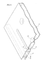
- Fig. 1 is an exploded perspective view showing a substantial part of a heat exchanger according to the present invention
- Fig. 2 is a sectional view showing the state of the assembling thereof
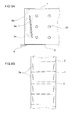
- Fig. 3 is an exploded perspective view showing the whole heat exchanger
- Fig. 4 is a perspective view showing the assembled state thereof
- Fig. 5 is a schematic sectional view of a substantial part taken on line V-V of Fig. 2
- Fig. 6 is a perspective view thereof.
- the heat exchanger has a core body 5, a large number of fins 7, a casing 9, a pair of header end lids 16 and 17, and a pair of slit blocks 6 as shown in Fig. 3.
- the core body 5, as shown in Fig. 1: is configured by turning up and bending a strip-shaped metal plate in a fanfold manner and forming turned-up end edges 1 and 2 alternately at one end and then the other end of a rectangular planar portion 1a; and has flat first flow channels 3 and second flow channels 4 alternately in the thickness direction of the metal plate.
- the space of each of the first flow channels 3 is formed so as to be smaller than that of each of the second flow channels 4. It goes without saying that the spaces of both the channels may be identical or reversed.
- a large number of dimples 29 are protrusively formed on the strip-shaped metal plate on the sides of the first flow channels 3.
- the tips of opposing dimples 29 touch each other and thereby the space of each of the first flow channels 3 is kept constant.
- Comb teeth 6b of the slit blocks 6 are fitted into the first flow channels 3 at both the ends of the turned-up end edges 1 and the fitted portions are brazed and fixed in an integrated manner.
- projecting stripes 3a protrude in a pair in each of the first flow channels 3 in proximity to and in parallel with each of the slit blocks 6.
- the projecting stripes 3a face each other and gaps 3c are formed between the projecting stripes 3a as shown in Figs. 5 and 6.
- the projecting stripes 3a are formed in all the first flow channels 3 and exist at both the ends of each of the first flow channels 3 in the longitudinal direction thereof as shown in Fig. 3.
- the projecting stripes 3a are formed so that the length thereof is smaller than the width of the core body 5 and placed at intermediate positions of the core body 5 in the width direction thereof. Further, the projecting stripes 3a are located at positions facing the ports 11 for cooling water 10 as shown in Fig. 2.
- the cooling water 10 flowing in from a port 11 is introduced to the projecting stripes 3a and reaches the vicinity of the turned-up end edges 1. Additionally, it is configured so that the cooling water 10 flows on the each part of the projecting stripes 3a also in the width direction as shown with the arrows (Fig. 2) through the gaps 3c between the opposing projecting stripes 3a, as shown in Fig. 5. As a result, the portions where the cooling water 10 stagnates disappear, the cooling water 10 flows uniformly in each part of the first flow channels 3, and the portions where the cooling water 10 boils disappear. Similar functions are carried out also on the side.of the exit of the cooling water 10.
- Each of the slit blocks 6 comprises a comb-shaped member 6a in this example.
- a tooth root 6c intersects with comb teeth 6b at right angles (Fig. 1).
- fins 7 are interposed into each of the second flow channels 4 as shown in Fig. 1.
- Fig. 1 is shown in the state where the first flow channel 3 on the top is lifted upward in order to facilitate visualization of the fins 7, in reality the bottom side of the uppermost first flow channel 3 touches the fin 7 on the top.
- the fins 7 are formed by bending a metal plate into a waveform in a transverse sectional direction; and curve also along the mountain ridges and valleys thereof in the longitudinal direction, and thereby the agitation effect of a fluid flowing in the second flow channels 4 is enhanced.
- a core 8 is composed of an assembly comprising the core body 5, the slit blocks 6, and the fins 7. Then it is also possible to insert slit fins, offset fins, or louver fins, those being not shown in the figures, in place of the fins 7 into the second flow channels 4.
- a casing 9 fitted to the outer circumference of the core 8 is formed into the shape of a tube the cross section of which is a rectangle the length of which is longer than that of the core 8; and has a pair of header sections 31 (refer to Fig. 2) on the outside of both the ends of the core 8.
- the casing 9 comprises a U-shaped member 9a and a lid 9b as shown in Figs. 3 and 4.
- the inner circumference of the U-shaped member 9a touches the upper and lower faces and one of the side faces of the core body 5 and blocks the communication between adjacent turned-up end edges 1 in the core body 5.
- the lid 9b closes: the opening side of the U-shaped member 9a; also the other side of the core body 5; and the openings 3b between the adjacent turned-up end edges 2.
- the U-shaped member 9a is made of a nickel steel having high thermal resistance and high corrosion resistance, a stainless steel, or the like; and prevents damages caused by a high temperature exhaust gas as the fluid to be cooled 12 flowing in the interior.
- the lid 9b may be a material inferior to the U-shaped member 9a in thermal resistance and corrosion resistance because the cooling water 10 flows along the inner surface thereof.
- a stainless steel that is inferior in thermal resistance and corrosion resistance has formability better than a material having high thermal resistance and high corrosion resistance and the material is less expensive.
- a pair of small tanks 28 is protrusively formed by press forming at both the end portions on the outside of the lid 9b, ports 11 open there respectively, and pipes 26 are connected to the ports 11. If a stainless steel that is somewhat inferior in thermal resistance and corrosion resistance is used, the small tanks 28 can be processed easily.
- header end lids 16 and 17 made of a highly thermal resistant and corrosion resistant material and flanges 25 are fitted further outside.
- Each of the header end lids 16 and 17 is bulged outward into the shape of a pan in the present example and a port through which the fluid to be cooled 12 flows opens in the center thereof.
- extension parts 16a and 17a are integrally formed on one side of the header end lids 16 and 17 respectively in an extended manner and the extension parts 16a and 17a cover the inner surface of both the ends (one end is omitted) of the lid 9b as shown in Fig. 2.
- a brazing metal is coated or disposed on each of the contact portions in such a heat exchanger and the whole body in the assembled state as shown in Figs. 2 and 4 is integrally brazed and fixed in a high temperature furnace.
- the cooling water 10 is supplied to the side of the first flow channels 3 and the fluid to be cooled 12 is supplied to the side of the second flow channels 4.
- the cooling water 10 is supplied to each of the first flow channels 3 through one of the pipes 26 and one of the small tanks 28, those being formed protrusively on one side of the casing 9, as shown in Fig. 2.
- a pair of upper and lower projecting stripes 3a is protrusively formed at the positions opposing the small tank 28 in the first flow channel 3a, and hence the cooling water 10 is guided by the projecting stripes 3a, flows between the projecting stripes 3a and comb teeth 6b, and reaches the vicinity of the turned-up end edges 1.
- a part of the cooling water 10 flowing between the projecting stripes 3a and comb teeth 6b passes through the gaps 3c between a pair of upper and lower projecting stripes 3a; and flows evenly at each part of the first flow channels 3 in the width direction as shown with the arrows.
- any one of the patterns (A) to (D) shown in Fig. 7 can be adopted for example.
- the pattern (A) is the case where both the end portions of each of the projecting stripes 3a are bent into an L-shape
- the pattern (B) is the case where both the end portions of each of the projecting stripes 3a are curved.
- the pattern (C) is the case where the whole length of each of the projecting stripes 3a is arched
- the pattern (D) is the case where the width of each of the projecting stripes 3a varies in the longitudinal direction.
- a pair of upper and lower projecting stripes 3a may be configured so as to intersect with each other in a plan view.
- the projecting stripes 3a are formed on a metal plate in a developed state beforehand so that the projecting stripes 3a may lean outward as shown in Fig. 8 (B) and the metal plate is formed in a fanfold manner at the turned-up end edges 1 and 2.
- the cooling water 10 flowing in each of the first flow channels 3 in the longitudinal direction goes toward the other pipe 26 and flows out to the exterior through the pipe 26.
- a pair of upper and lower projecting stripes 3a exists at the exit side too, and thus the cooling water 10 is guided by the projecting stripes 3a and smoothly flows without yielding stagnated portions.
- the fluid to be cooled 12 comprising a high temperature exhaust gas is supplied to each of the second flow channels 4 from the opening of the header end lid 16 through one of the openings 13 of the casing 9.
Abstract
Description
- The present invention relates to a heat exchanger having a simple structure and being easily produced, which can be used as a heat exchanger (EGR cooler) used in an exhaust gas recirculation apparatus of an automobile or another heat exchanger.
- A conventional EGR cooler comprises an assembly of a large number of flat tubes or plates, a large number of fins, a casing, and a header, wherein cooling water is made to flow on the side of the casing and an exhaust gas is made to flow in the interior of the flat tubes or the like as the invention disclosed in
Japanese Unexamined Patent Publication No. 2003-90693 - The drawbacks of such a heat exchanger as an EGR cooler or the like have been that: the number of parts is large, which makes assembling cumbersome; and the number of brazed portions of each component increases, which causes leakage to tend to occur at the brazed portions. Moreover, it has been feared that the portions where a fluid stagnates may be caused in a flow channel and cooling water may partially come to a boil.
- In order to prevent those drawbacks from occurring, in the invention disclosed in the aforementioned Japanese patent publication: a pair of blocking projecting stripes is intermittently provided particularly on the outer surface of a tube at the downstream position of an inlet for cooling water; the cooling water is injected from an inlet pipe and collided with the casing facing the inlet pipe; the reflecting streams are introduced to the projecting stripes and then introduced to an intermediate portion where no stripes exist. The drawbacks thereof have been that the production of such a tube is cumbersome and the cooling water does not flow evenly in each part on a tube surface.
- In view of the above situation, an object of the present invention is to provide a heat exchanger that: has a small number of parts; is easy to assemble; has a small number of brazed portions; is highly reliable; can flow cooling water evenly to each part; and does not cause partial boiling.
- The present invention described in
Claim 1 is a heat exchanger wherein: - a core body (5) is configured by turning up and bending a strip-shaped metal plate in a fanfold manner and forming turned-up end edges (1) and (2) alternately at one end and then the other end of a rectangular planar portion (1a), and has flat first flow channels (3) and second flow channels (4) alternately in the thickness direction of the metal plate;
- the first flow channels (3) of the core body (5) are blocked with slit blocks (6) comprising long boards or bars at both the ends of each of the turned-up end edges (1), flat openings (3b) are formed only on one side, fins (7) are interposed in the second flow channels (4), and thus a core (8) is formed;
- the outer circumference of the core body (5) is fitted in a tubular casing (9) and thereby communication between adjacent turned-up end edges (1) and (2) is blocked;
- a pair of ports (11) for cooling water (10) is formed at both the end portions of the casing (9) on the side facing the side of the openings (3b) of the first flow channels (3) ;
- projecting stripes (3a) are bent and formed on the opposing planes in each of the first flow channels (3) in proximity to and along the slit blocks (6) at the positions opposing the ports (11), and gaps (3c) are formed between the respective projecting stripes (3a);
- the cooling water (10) is introduced into the respective first flow channels (3) from one of the ports (11), and a part of the introduced cooling water (10) is guided by the projecting stripes (3a) and passes through between the pair of opposing projecting stripes (3a); and
- a fluid to be cooled (12) is introduced from one cylindrical opening (13) of the casing (9) to the other opening (13) through the respective second flow channels (4) .
- The present invention described in
Claim 2 is a heat exchanger according toClaim 1 that is configured so that the gaps (3c) between the projecting stripes (3a) may vary along the longitudinal direction. - The present invention described in
Claim 3 is a heat exchanger according toClaim 2, wherein the gaps (3c) at intermediate portions of the projecting stripes (3a) in the longitudinal direction thereof are formed so as to be larger or smaller than the gaps at both the ends. - The present invention described in
Claim 4 is a heat exchanger according toClaim 1, wherein the pair of opposing projecting stripes (3a) is formed so as to intersect with each other in a plan view. - The present invention described in
Claim 5 is a heat exchanger according to any one ofClaims 1 to 4, wherein at least both the ends of the projecting stripes (3a) in the longitudinal direction thereof curve to the side of the center of each of the first flow channels (3). - The present invention described in
Claim 6 is a heat exchanger according to any one ofClaims 1 to 5 that is configured so that the width of each of the projecting stripes (3a) may vary along the longitudinal direction thereof. - A heat exchanger according to the present invention is configured as stated above and exhibits the following effects.
- A heat exchanger according to the present invention is configured by: building a
core 8 with acore body 5 formed by turning up a strip-shaped metal plate in a fanfold manner,slit blocks 6, andfins 7; and fitting the outer circumference of thecore 8 in acasing 9. Hence it is possible to provide a heat exchanger having a small number of parts, being produced easily, and having a simple structure at a low cost. - Moreover, the number of joints decreases and air-tightness and liquid-tightness improve, and it is possible to provide a heat exchanger that is compact and excellent in performance. Further, a pair of projecting
stripes 3a is formed in each of thefirst flow channels 3 at the ports, thus it is possible to prevent cooling water from stagnating in the vicinity of the ports, thengaps 3c are provided between the pair of theprojecting stripes 3a, therefore the cooling water flows also through thegaps 3c, and hence the cooling water flows evenly in each part and the heat exchange is accelerated. - In the above configuration, it is possible to: vary the
gaps 3c between theprojecting stripes 3a along the longitudinal direction; and finely adjust the uniform flow of the cooling water in response to various conditions. - Yet further, by configuring the
gaps 3c at intermediate portions of the projectingstripes 3a in the longitudinal direction so as to be larger or smaller than the gaps at both the ends, it is possible to finely adjust the uniform flow of the cooling water in response to various conditions by another method. - Furthermore, by forming the pair of
opposing projecting stripes 3a so as to intersect with each other in a plan view, it is possible to finely adjust the uniform flow of the cooling water in response to various conditions by yet another method. - In addition, by curving both the ends of the projecting
stripes 3a in the longitudinal direction thereof on the side of the center of each of the first flow channels, it is possible to smoothen the flow of the cooling water. - Otherwise, by varying the width of each of the
projecting stripes 3a along the longitudinal direction, it is possible to finely adjust the uniform flow of the cooling water in response to various conditions by another method. -
- Fig. 1 is an exploded perspective view showing a substantial part of the core section of a heat exchanger according to the present invention.
- Fig. 2 is a sectional view showing a substantial part of the heat exchanger in the state of assembling.
- Fig. 3 is an exploded perspective view showing the whole heat exchanger.
- Fig. 4 is a perspective view showing the assembled state of the heat exchanger.
- Fig. 5 is a schematic sectional view taken on line V-V of Fig. 2.
- Fig. 6 is a schematic perspective view showing the cross section.
- Figs. 7(A) to 7(D) are plan views showing examples of each of projecting
stripes 3a of a heat exchanger. - Figs. 8 (A) and 8 (B) are a plan view showing another example of each of the
projecting stripes 3a and a view illustrating the production process. - Figs. 9 (A) to 9(C) are sectional views showing examples of various kinds of
gaps 3c between theprojecting stripes 3a. - Next, embodiments according to the present invention will be described in reference to drawings.
- Fig. 1 is an exploded perspective view showing a substantial part of a heat exchanger according to the present invention, Fig. 2 is a sectional view showing the state of the assembling thereof, Fig. 3 is an exploded perspective view showing the whole heat exchanger, Fig. 4 is a perspective view showing the assembled state thereof, Fig. 5 is a schematic sectional view of a substantial part taken on line V-V of Fig. 2, and Fig. 6 is a perspective view thereof.
- The heat exchanger has a
core body 5, a large number offins 7, acasing 9, a pair ofheader end lids slit blocks 6 as shown in Fig. 3. - The
core body 5, as shown in Fig. 1: is configured by turning up and bending a strip-shaped metal plate in a fanfold manner and forming turned-upend edges first flow channels 3 andsecond flow channels 4 alternately in the thickness direction of the metal plate. In the example, the space of each of thefirst flow channels 3 is formed so as to be smaller than that of each of thesecond flow channels 4. It goes without saying that the spaces of both the channels may be identical or reversed. - Here, a large number of
dimples 29 are protrusively formed on the strip-shaped metal plate on the sides of thefirst flow channels 3. In the example, the tips ofopposing dimples 29 touch each other and thereby the space of each of thefirst flow channels 3 is kept constant.Comb teeth 6b of theslit blocks 6 are fitted into thefirst flow channels 3 at both the ends of the turned-upend edges 1 and the fitted portions are brazed and fixed in an integrated manner. - Further, projecting
stripes 3a protrude in a pair in each of thefirst flow channels 3 in proximity to and in parallel with each of theslit blocks 6. The projectingstripes 3a face each other andgaps 3c are formed between the projectingstripes 3a as shown in Figs. 5 and 6. Theprojecting stripes 3a are formed in all thefirst flow channels 3 and exist at both the ends of each of thefirst flow channels 3 in the longitudinal direction thereof as shown in Fig. 3. - Then, the projecting
stripes 3a are formed so that the length thereof is smaller than the width of thecore body 5 and placed at intermediate positions of thecore body 5 in the width direction thereof. Further, the projectingstripes 3a are located at positions facing the ports 11 for coolingwater 10 as shown in Fig. 2. - Then, it is designed so that the
cooling water 10 flowing in from a port 11 is introduced to the projectingstripes 3a and reaches the vicinity of the turned-upend edges 1. Additionally, it is configured so that thecooling water 10 flows on the each part of theprojecting stripes 3a also in the width direction as shown with the arrows (Fig. 2) through thegaps 3c between theopposing projecting stripes 3a, as shown in Fig. 5. As a result, the portions where thecooling water 10 stagnates disappear, thecooling water 10 flows uniformly in each part of thefirst flow channels 3, and the portions where thecooling water 10 boils disappear. Similar functions are carried out also on the side.of the exit of thecooling water 10. - Each of the
slit blocks 6 comprises a comb-shaped member 6a in this example. In the comb-shaped member 6a, atooth root 6c intersects withcomb teeth 6b at right angles (Fig. 1). - Next,
fins 7 are interposed into each of thesecond flow channels 4 as shown in Fig. 1. Here, although Fig. 1 is shown in the state where thefirst flow channel 3 on the top is lifted upward in order to facilitate visualization of thefins 7, in reality the bottom side of the uppermostfirst flow channel 3 touches thefin 7 on the top. The fins 7: are formed by bending a metal plate into a waveform in a transverse sectional direction; and curve also along the mountain ridges and valleys thereof in the longitudinal direction, and thereby the agitation effect of a fluid flowing in thesecond flow channels 4 is enhanced. - A
core 8 is composed of an assembly comprising thecore body 5, the slit blocks 6, and thefins 7. Then it is also possible to insert slit fins, offset fins, or louver fins, those being not shown in the figures, in place of thefins 7 into thesecond flow channels 4. - Next, a
casing 9 fitted to the outer circumference of the core 8: is formed into the shape of a tube the cross section of which is a rectangle the length of which is longer than that of thecore 8; and has a pair of header sections 31 (refer to Fig. 2) on the outside of both the ends of thecore 8. In this example, thecasing 9 comprises aU-shaped member 9a and alid 9b as shown in Figs. 3 and 4. - The inner circumference of the
U-shaped member 9a touches the upper and lower faces and one of the side faces of thecore body 5 and blocks the communication between adjacent turned-up end edges 1 in thecore body 5. Thelid 9b closes: the opening side of theU-shaped member 9a; also the other side of thecore body 5; and theopenings 3b between the adjacent turned-up end edges 2. TheU-shaped member 9a: is made of a nickel steel having high thermal resistance and high corrosion resistance, a stainless steel, or the like; and prevents damages caused by a high temperature exhaust gas as the fluid to be cooled 12 flowing in the interior. - In contrast, the
lid 9b may be a material inferior to theU-shaped member 9a in thermal resistance and corrosion resistance because the coolingwater 10 flows along the inner surface thereof. In general, a stainless steel that is inferior in thermal resistance and corrosion resistance has formability better than a material having high thermal resistance and high corrosion resistance and the material is less expensive. In the present example, as shown in Fig. 3, a pair ofsmall tanks 28 is protrusively formed by press forming at both the end portions on the outside of thelid 9b, ports 11 open there respectively, andpipes 26 are connected to the ports 11. If a stainless steel that is somewhat inferior in thermal resistance and corrosion resistance is used, thesmall tanks 28 can be processed easily. - Here, the end edges of both the sidewalls of the
U-shaped member 9a are fitted into fitting edge portions 15 (Fig. 1) turned up and formed at both the upper and lower ends of thecore body 5. Then L-shaped portions at both the upper and lower ends of thelid 9b are fitted to the outsides of thefitting edge portions 15. - Thus, the reliability of brazing at connections between the
lid 9b, theU-shaped member 9a, and thecore body 5 can be improved. - Next, opening ends of
header sections 31 at both the ends of thecasing 9 in the longitudinal direction are closed with a pair ofheader end lids flanges 25 are fitted further outside. Each of theheader end lids extension parts header end lids extension parts lid 9b as shown in Fig. 2. - A brazing metal is coated or disposed on each of the contact portions in such a heat exchanger and the whole body in the assembled state as shown in Figs. 2 and 4 is integrally brazed and fixed in a high temperature furnace.
- Then as shown in Figs. 2 and 4, the cooling
water 10 is supplied to the side of thefirst flow channels 3 and the fluid to be cooled 12 is supplied to the side of thesecond flow channels 4. - The cooling
water 10 is supplied to each of thefirst flow channels 3 through one of thepipes 26 and one of thesmall tanks 28, those being formed protrusively on one side of thecasing 9, as shown in Fig. 2. On that occasion, a pair of upper and lower projectingstripes 3a is protrusively formed at the positions opposing thesmall tank 28 in thefirst flow channel 3a, and hence the coolingwater 10 is guided by the projectingstripes 3a, flows between the projectingstripes 3a and combteeth 6b, and reaches the vicinity of the turned-up end edges 1. Moreover, a part of the coolingwater 10 flowing between the projectingstripes 3a and combteeth 6b: passes through thegaps 3c between a pair of upper and lower projectingstripes 3a; and flows evenly at each part of thefirst flow channels 3 in the width direction as shown with the arrows. - Here, in order for the cooling
water 10 to flow evenly at each part of thefirst flow channels 3 in the width direction with a high degree of accuracy, it is required to: decide various conditions through flow tests of the coolingwater 10; and then adopt an optimum shape of the projectingstripes 3a and an optimum height of thegaps 3c between the respective projectingstripes 3a. As the shape of each of the projectingstripes 3a in a plan view, any one of the patterns (A) to (D) shown in Fig. 7 can be adopted for example. The pattern (A) is the case where both the end portions of each of the projectingstripes 3a are bent into an L-shape, and the pattern (B) is the case where both the end portions of each of the projectingstripes 3a are curved. Then the pattern (C) is the case where the whole length of each of the projectingstripes 3a is arched, and the pattern (D) is the case where the width of each of the projectingstripes 3a varies in the longitudinal direction. - Further, as shown in Fig. 8(A), a pair of upper and lower projecting
stripes 3a may be configured so as to intersect with each other in a plan view. On this occasion, the projectingstripes 3a are formed on a metal plate in a developed state beforehand so that the projectingstripes 3a may lean outward as shown in Fig. 8 (B) and the metal plate is formed in a fanfold manner at the turned-up end edges 1 and 2. - Here, in Fig. 8 (A), the tip of each of the
comb teeth 6b of the slit blocks 6 is curved and the coolingwater 10 flows smoothly along the curved tip. Thereby, the stagnation of the coolingwater 10 can be avoided further effectively. - The cooling
water 10 flowing in each of thefirst flow channels 3 in the longitudinal direction goes toward theother pipe 26 and flows out to the exterior through thepipe 26. On this occasion, a pair of upper and lower projectingstripes 3a exists at the exit side too, and thus the coolingwater 10 is guided by the projectingstripes 3a and smoothly flows without yielding stagnated portions. - Next, for example, the fluid to be cooled 12 comprising a high temperature exhaust gas is supplied to each of the
second flow channels 4 from the opening of theheader end lid 16 through one of theopenings 13 of thecasing 9.
Claims (6)
- A heat exchanger wherein:a core body (5) is configured by turning up and bending a strip-shaped metal plate in a fanfold manner and forming turned-up end edges (1) and (2) alternately at one end and then the other end of a rectangular planar portion (1a), and has flat first flow channels (3) and second flow channels (4) alternately in the thickness direction of the metal plate;the first flow channels (3) of the core body (5) are blocked with slit blocks (6) comprising long boards or bars at both the ends of each of said turned-up end edges (1), flat openings (3b) are formed only on one side, fins (7) are interposed in said second flow channels (4), and thus a core (8) is formed;the outer circumference of the core body (5) is fitted in a tubular casing (9) and thereby communication between adjacent turned-up end edges (1) and (2) is blocked;a pair of ports (11) for cooling water (10) is formed at both the end portions of the casing (9) on the side facing the side of said openings (3b) of said first flow channels (3) ;projecting stripes (3a) are bent and formed on the opposing planes in each of said first flow channels (3) in proximity to and along said slit blocks (6) at the positions opposing the ports (11), and gaps (3c) are formed between the respective projecting stripes (3a);said cooling water (10) is introduced into the respective first flow channels (3) from said ports (11), and a part of said introduced cooling water (10) is guided by said projecting stripes (3a) and passes through between the pair of opposing projecting stripes (3a); anda fluid to be cooled (12) is introduced from one cylindrical opening (13) of said casing (9) to the other opening (13) through the respective second flow channels (4).
- The heat exchanger according to Claim 1, configured so that the gaps (3c) between said projecting stripes (3a) may vary along the longitudinal direction.
- The heat exchanger according to Claim 2, wherein the gaps (3c) at intermediate portions of the projecting stripes (3a) in the longitudinal direction thereof are formed so as to be larger or smaller than the gaps at both the ends.
- The heat exchanger according to Claim 1, wherein the pair of opposing projecting stripes (3a) is formed so as to intersect with each other in a plan view.
- The heat exchanger according to any one of Claims 1 to 4, wherein at least both the ends of the projecting stripes (3a) in the longitudinal direction thereof curve to the side of the center of each of the first flow channels (3).
- The heat exchanger according to any one of Claims 1 to 5, configured so that the width of each of said projecting stripes (3a) may vary along the longitudinal direction thereof.
Applications Claiming Priority (2)
| Application Number | Priority Date | Filing Date | Title |
|---|---|---|---|
| JP2005018277A JP4527557B2 (en) | 2005-01-26 | 2005-01-26 | Heat exchanger |
| PCT/JP2005/023005 WO2006080152A1 (en) | 2005-01-26 | 2005-12-08 | Heat exchanger |
Publications (3)
| Publication Number | Publication Date |
|---|---|
| EP1843117A1 true EP1843117A1 (en) | 2007-10-10 |
| EP1843117A4 EP1843117A4 (en) | 2010-05-05 |
| EP1843117B1 EP1843117B1 (en) | 2011-07-20 |
Family
ID=36740186
Family Applications (1)
| Application Number | Title | Priority Date | Filing Date |
|---|---|---|---|
| EP05816689A Expired - Fee Related EP1843117B1 (en) | 2005-01-26 | 2005-12-08 | Heat exchanger |
Country Status (5)
| Country | Link |
|---|---|
| US (1) | US7857039B2 (en) |
| EP (1) | EP1843117B1 (en) |
| JP (1) | JP4527557B2 (en) |
| CN (1) | CN100489431C (en) |
| WO (1) | WO2006080152A1 (en) |
Cited By (6)
| Publication number | Priority date | Publication date | Assignee | Title |
|---|---|---|---|---|
| EP1930681A1 (en) * | 2006-11-30 | 2008-06-11 | Behr GmbH & Co. KG | Heat exchanger, arrangement and method for manufacturing a heat exchanger |
| EP2136174A2 (en) * | 2008-06-16 | 2009-12-23 | Benteler Automobiltechnik GmbH & Co. KG | Exhaust gas heat exchanger |
| EP2284471A3 (en) * | 2009-07-31 | 2013-12-18 | Pierburg GmbH | Cooling device for a combustion engine |
| WO2014040797A1 (en) * | 2012-09-17 | 2014-03-20 | Behr Gmbh & Co. Kg | Heat exchanger |
| EP2642232A3 (en) * | 2012-03-21 | 2014-08-20 | Energy Wall LLC | Multiple opening counter flow plate exchanger and method of making |
| WO2019025750A1 (en) * | 2017-08-04 | 2019-02-07 | Hieta Technologies Limited | Heat exchanger |
Families Citing this family (52)
| Publication number | Priority date | Publication date | Assignee | Title |
|---|---|---|---|---|
| JP4416421B2 (en) * | 2003-03-18 | 2010-02-17 | テルモ株式会社 | Guide wire and manufacturing method thereof |
| US8047272B2 (en) * | 2005-09-13 | 2011-11-01 | Catacel Corp. | High-temperature heat exchanger |
| US7591301B2 (en) * | 2005-09-13 | 2009-09-22 | Catacel Corp. | Low-cost high-temperature heat exchanger |
| US7594326B2 (en) * | 2005-09-13 | 2009-09-29 | Catacel Corp. | Method for making a low-cost high-temperature heat exchanger |
| JP5283836B2 (en) | 2006-07-25 | 2013-09-04 | 富士通株式会社 | Heat receiver and liquid cooling unit for liquid cooling unit and electronic device |
| JP5148079B2 (en) * | 2006-07-25 | 2013-02-20 | 富士通株式会社 | Heat exchanger for liquid cooling unit, liquid cooling unit and electronic equipment |
| JP4842040B2 (en) * | 2006-07-25 | 2011-12-21 | 富士通株式会社 | Electronics |
| JP5133531B2 (en) * | 2006-07-25 | 2013-01-30 | 富士通株式会社 | Heat exchanger for liquid cooling unit, liquid cooling unit and electronic equipment |
| JP2008027374A (en) * | 2006-07-25 | 2008-02-07 | Fujitsu Ltd | Heat receiver for liquid cooling unit, liquid cooling unit, and electronic device |
| JP4781929B2 (en) * | 2006-07-25 | 2011-09-28 | 富士通株式会社 | Electronics |
| JP2008027370A (en) * | 2006-07-25 | 2008-02-07 | Fujitsu Ltd | Electronic device |
| CA2701760A1 (en) * | 2007-10-08 | 2009-04-16 | Catacel Corp. | High-temperature heat exchanger |
| DE102007048824B4 (en) * | 2007-10-10 | 2018-02-22 | Mahle International Gmbh | Heat exchanger, in particular for exhaust gas cooling |
| JP2009097840A (en) * | 2007-10-19 | 2009-05-07 | T Rad Co Ltd | Heat exchanger |
| JP5226393B2 (en) * | 2008-06-12 | 2013-07-03 | 株式会社ティラド | Heat exchanger |
| JP2010048536A (en) | 2008-08-25 | 2010-03-04 | Denso Corp | Heat exchanger |
| US20140060789A1 (en) * | 2008-10-03 | 2014-03-06 | Modine Manufacturing Company | Heat exchanger and method of operating the same |
| JP5321271B2 (en) | 2009-06-17 | 2013-10-23 | 株式会社デンソー | Heat exchanger for high temperature gas cooling |
| JP5510027B2 (en) * | 2010-04-21 | 2014-06-04 | トヨタ自動車株式会社 | EGR cooler |
| JP2012141096A (en) * | 2010-12-28 | 2012-07-26 | Mitsubishi Heavy Ind Ltd | Method for manufacturing hot-water heater, and hot-water heater manufactured thereby |
| CN103429982B (en) * | 2011-02-04 | 2016-06-29 | 洛克希德马丁公司 | There is the heat exchanger of foam fin |
| US9464847B2 (en) | 2011-02-04 | 2016-10-11 | Lockheed Martin Corporation | Shell-and-tube heat exchangers with foam heat transfer units |
| WO2012106601A2 (en) | 2011-02-04 | 2012-08-09 | Lockheed Martin Corporation | Radial-flow heat exchanger with foam heat exchange fins |
| US9951997B2 (en) | 2011-02-04 | 2018-04-24 | Lockheed Martin Corporation | Staged graphite foam heat exchangers |
| EP2522845A1 (en) * | 2011-05-11 | 2012-11-14 | Borgwarner Emission Systems Spain, S.L. | Heat exchanger for cooling a gas |
| JP5763462B2 (en) * | 2011-07-29 | 2015-08-12 | 株式会社ティラド | Header plateless heat exchanger |
| CN102278903A (en) * | 2011-08-16 | 2011-12-14 | 李永堂 | Plate-type heat exchanger |
| US20130048261A1 (en) * | 2011-08-26 | 2013-02-28 | Hs Marston Aerospace Ltd. | Heat exhanger |
| JP5585558B2 (en) * | 2011-09-24 | 2014-09-10 | 株式会社デンソー | Exhaust heat exchanger |
| JP5768795B2 (en) * | 2011-10-18 | 2015-08-26 | カルソニックカンセイ株式会社 | Exhaust heat exchanger |
| DE102011085479A1 (en) | 2011-10-28 | 2013-05-02 | Behr Gmbh & Co. Kg | Heat exchanger |
| US20130133869A1 (en) * | 2011-11-28 | 2013-05-30 | Dana Canada Corporation | Heat Exchanger With End Seal For Blocking Off Air Bypass Flow |
| JP2014081175A (en) * | 2012-10-18 | 2014-05-08 | T Rad Co Ltd | Casing connection structure of exhaust heat exchanger |
| US9151546B2 (en) * | 2013-02-28 | 2015-10-06 | General Electric Company | Heat exchanger assembly |
| JP6007838B2 (en) * | 2013-03-22 | 2016-10-12 | トヨタ自動車株式会社 | Heat exchanger |
| FR3004527B1 (en) * | 2013-04-16 | 2015-05-15 | Fives Cryo | HEAT EXCHANGER WITH DOUBLE-FUNCTION DISTRIBUTION HEAD CONNECTION ASSEMBLY |
| JP5989619B2 (en) * | 2013-09-13 | 2016-09-07 | 株式会社ティラド | Header plateless heat exchanger tank structure |
| CN103791759B (en) * | 2014-03-07 | 2016-03-30 | 丹佛斯微通道换热器(嘉兴)有限公司 | For plate type heat exchanger heat exchanger plate and there is the plate type heat exchanger of this heat exchanger plate |
| CA2955854A1 (en) * | 2014-07-21 | 2016-01-28 | Dana Canada Corporation | Heat exchanger with flow obstructions to reduce fluid dead zones |
| US10161690B2 (en) * | 2014-09-22 | 2018-12-25 | Hamilton Sundstrand Space Systems International, Inc. | Multi-layer heat exchanger and method of distributing flow within a fluid layer of a multi-layer heat exchanger |
| KR101846660B1 (en) * | 2016-04-20 | 2018-04-09 | 현대자동차주식회사 | Egr cooler for vehicle |
| DE102017223616A1 (en) * | 2017-12-21 | 2019-06-27 | Mahle International Gmbh | Flat tube for an exhaust gas cooler |
| JP7129744B2 (en) * | 2018-08-06 | 2022-09-02 | 三恵技研工業株式会社 | Exhaust heat recovery equipment for automobiles |
| JP7182395B2 (en) * | 2018-08-09 | 2022-12-02 | リンナイ株式会社 | Heat exchanger |
| KR102522108B1 (en) * | 2018-08-27 | 2023-04-17 | 한온시스템 주식회사 | Heat exchanger of exhaust heat recovery device |
| US11255534B2 (en) * | 2018-10-03 | 2022-02-22 | Coretronic Corporation | Thermal module and projector |
| JP7159806B2 (en) * | 2018-11-21 | 2022-10-25 | トヨタ自動車株式会社 | Heat exchanger |
| KR20200101645A (en) * | 2019-02-20 | 2020-08-28 | 현대자동차주식회사 | Egr cooler and engine system with the same |
| JP7286362B2 (en) * | 2019-03-20 | 2023-06-05 | 株式会社ティラド | Header plateless heat exchanger |
| DE102020104538A1 (en) | 2020-02-20 | 2021-08-26 | Faurecia Emissions Control Technologies, Germany Gmbh | Heat exchanger housing and method of manufacturing a heat exchanger |
| US11280559B2 (en) * | 2020-05-12 | 2022-03-22 | Hanon Systems | Dumbbell shaped plate fin |
| CN112682500B (en) * | 2020-12-31 | 2023-05-26 | 南宁市安和机械设备有限公司 | Oil cooler made of staggered dotting oil cooler tube |
Family Cites Families (18)
| Publication number | Priority date | Publication date | Assignee | Title |
|---|---|---|---|---|
| US3734177A (en) * | 1972-02-04 | 1973-05-22 | Modine Mfg Co | Heat exchanger |
| US3829945A (en) * | 1973-07-11 | 1974-08-20 | Motoren Werke Mannheim Ag | Method of producing a heat exchanger |
| US4384611A (en) * | 1978-05-15 | 1983-05-24 | Hxk Inc. | Heat exchanger |
| JPS55118598A (en) * | 1979-03-06 | 1980-09-11 | Braun Kk | Heat exchanger |
| JPH02133569A (en) | 1988-11-15 | 1990-05-22 | Kawasaki Steel Corp | Hollow cathode gun for ion plating |
| JPH02133569U (en) * | 1989-04-07 | 1990-11-06 | ||
| US5282507A (en) * | 1991-07-08 | 1994-02-01 | Yazaki Corporation | Heat exchange system |
| US6983788B2 (en) * | 1998-11-09 | 2006-01-10 | Building Performance Equipment, Inc. | Ventilating system, heat exchanger and methods |
| CN2201284Y (en) * | 1994-08-07 | 1995-06-21 | 浙江省嵊县康艺换热器厂 | Automotive fin plate heat exchanger |
| PL328749A1 (en) * | 1998-09-21 | 2000-03-27 | Andrzej Sokulski | Panel-type heat exchanger |
| DE19846518B4 (en) * | 1998-10-09 | 2007-09-20 | Modine Manufacturing Co., Racine | Heat exchangers, in particular for gases and liquids |
| CN1285500A (en) * | 1999-08-20 | 2001-02-28 | 瓦莱奥空调技术有限公司 | Finned flat tube type heat-exchanger for car |
| JP2002318095A (en) * | 2001-04-18 | 2002-10-31 | Furukawa Electric Co Ltd:The | Heat exchanger |
| US6408941B1 (en) * | 2001-06-29 | 2002-06-25 | Thermal Corp. | Folded fin plate heat-exchanger |
| JP4221931B2 (en) | 2001-07-10 | 2009-02-12 | 株式会社デンソー | Exhaust heat exchanger |
| DE10233407B4 (en) * | 2001-07-26 | 2016-02-18 | Denso Corporation | Exhaust gas heat exchanger |
| DE10302948A1 (en) * | 2003-01-24 | 2004-08-05 | Behr Gmbh & Co. Kg | Heat exchanger, in particular exhaust gas cooler for motor vehicles |
| US7159649B2 (en) * | 2004-03-11 | 2007-01-09 | Thermal Corp. | Air-to-air heat exchanger |
-
2005
- 2005-01-26 JP JP2005018277A patent/JP4527557B2/en not_active Expired - Fee Related
- 2005-12-08 US US11/795,997 patent/US7857039B2/en not_active Expired - Fee Related
- 2005-12-08 WO PCT/JP2005/023005 patent/WO2006080152A1/en active Application Filing
- 2005-12-08 CN CNB2005800469526A patent/CN100489431C/en not_active Expired - Fee Related
- 2005-12-08 EP EP05816689A patent/EP1843117B1/en not_active Expired - Fee Related
Non-Patent Citations (2)
| Title |
|---|
| No further relevant documents disclosed * |
| See also references of WO2006080152A1 * |
Cited By (11)
| Publication number | Priority date | Publication date | Assignee | Title |
|---|---|---|---|---|
| EP1930681A1 (en) * | 2006-11-30 | 2008-06-11 | Behr GmbH & Co. KG | Heat exchanger, arrangement and method for manufacturing a heat exchanger |
| EP2136174A2 (en) * | 2008-06-16 | 2009-12-23 | Benteler Automobiltechnik GmbH & Co. KG | Exhaust gas heat exchanger |
| EP2136174A3 (en) * | 2008-06-16 | 2012-12-05 | Benteler Automobiltechnik GmbH | Exhaust gas heat exchanger |
| EP3270083A1 (en) * | 2008-06-16 | 2018-01-17 | Benteler Automobiltechnik GmbH | Exhaust gas heat exchanger |
| EP2284471A3 (en) * | 2009-07-31 | 2013-12-18 | Pierburg GmbH | Cooling device for a combustion engine |
| EP2284470A3 (en) * | 2009-07-31 | 2013-12-18 | Pierburg GmbH | Cooling device for a combustion engine |
| EP2642232A3 (en) * | 2012-03-21 | 2014-08-20 | Energy Wall LLC | Multiple opening counter flow plate exchanger and method of making |
| WO2014040797A1 (en) * | 2012-09-17 | 2014-03-20 | Behr Gmbh & Co. Kg | Heat exchanger |
| US9683786B2 (en) | 2012-09-17 | 2017-06-20 | Mahle International Gmbh | Heat exchanger |
| WO2019025750A1 (en) * | 2017-08-04 | 2019-02-07 | Hieta Technologies Limited | Heat exchanger |
| US11359872B2 (en) | 2017-08-04 | 2022-06-14 | Hieta Technologies Limited | Heat exchanger |
Also Published As
| Publication number | Publication date |
|---|---|
| CN100489431C (en) | 2009-05-20 |
| EP1843117B1 (en) | 2011-07-20 |
| JP4527557B2 (en) | 2010-08-18 |
| EP1843117A4 (en) | 2010-05-05 |
| JP2006207887A (en) | 2006-08-10 |
| WO2006080152A1 (en) | 2006-08-03 |
| CN101103244A (en) | 2008-01-09 |
| US7857039B2 (en) | 2010-12-28 |
| US20080164014A1 (en) | 2008-07-10 |
Similar Documents
| Publication | Publication Date | Title |
|---|---|---|
| US7857039B2 (en) | Heat exchanger | |
| EP1795850B1 (en) | Heat exchanger | |
| EP3156753B1 (en) | Heat exchanger having wave pin plate for reducing egr gas pressure difference | |
| US6820682B2 (en) | Heat exchanger | |
| EP3650799B1 (en) | A fin body for a heat exchange tube | |
| US8544454B2 (en) | Heat exchanger for a motor vehicle | |
| JP4143966B2 (en) | Flat tube for EGR cooler | |
| US8020610B2 (en) | Exhaust gas heat exchanger and method of operating the same | |
| JP4920382B2 (en) | EGR cooler | |
| CN111512109B (en) | Header-plate-free heat exchanger | |
| KR20170037003A (en) | EGR cooler for vehicle | |
| JP2007225192A (en) | Heat exchanger |
Legal Events
| Date | Code | Title | Description |
|---|---|---|---|
| PUAI | Public reference made under article 153(3) epc to a published international application that has entered the european phase |
Free format text: ORIGINAL CODE: 0009012 |
|
| 17P | Request for examination filed |
Effective date: 20070720 |
|
| AK | Designated contracting states |
Kind code of ref document: A1 Designated state(s): CZ DE IT |
|
| DAX | Request for extension of the european patent (deleted) | ||
| RBV | Designated contracting states (corrected) |
Designated state(s): CZ DE IT |
|
| A4 | Supplementary search report drawn up and despatched |
Effective date: 20100401 |
|
| GRAP | Despatch of communication of intention to grant a patent |
Free format text: ORIGINAL CODE: EPIDOSNIGR1 |
|
| RIN1 | Information on inventor provided before grant (corrected) |
Inventor name: NAKAMURA, YOICHI |
|
| GRAS | Grant fee paid |
Free format text: ORIGINAL CODE: EPIDOSNIGR3 |
|
| GRAA | (expected) grant |
Free format text: ORIGINAL CODE: 0009210 |
|
| AK | Designated contracting states |
Kind code of ref document: B1 Designated state(s): CZ DE IT |
|
| REG | Reference to a national code |
Ref country code: DE Ref legal event code: R096 Ref document number: 602005029128 Country of ref document: DE Effective date: 20110915 |
|
| PLBE | No opposition filed within time limit |
Free format text: ORIGINAL CODE: 0009261 |
|
| STAA | Information on the status of an ep patent application or granted ep patent |
Free format text: STATUS: NO OPPOSITION FILED WITHIN TIME LIMIT |
|
| 26N | No opposition filed |
Effective date: 20120423 |
|
| REG | Reference to a national code |
Ref country code: DE Ref legal event code: R097 Ref document number: 602005029128 Country of ref document: DE Effective date: 20120423 |
|
| PGFP | Annual fee paid to national office [announced via postgrant information from national office to epo] |
Ref country code: IT Payment date: 20161221 Year of fee payment: 12 |
|
| PGFP | Annual fee paid to national office [announced via postgrant information from national office to epo] |
Ref country code: DE Payment date: 20171206 Year of fee payment: 13 Ref country code: CZ Payment date: 20171113 Year of fee payment: 13 |
|
| PG25 | Lapsed in a contracting state [announced via postgrant information from national office to epo] |
Ref country code: IT Free format text: LAPSE BECAUSE OF NON-PAYMENT OF DUE FEES Effective date: 20171208 |
|
| REG | Reference to a national code |
Ref country code: DE Ref legal event code: R119 Ref document number: 602005029128 Country of ref document: DE |
|
| PG25 | Lapsed in a contracting state [announced via postgrant information from national office to epo] |
Ref country code: CZ Free format text: LAPSE BECAUSE OF NON-PAYMENT OF DUE FEES Effective date: 20181208 |
|
| PG25 | Lapsed in a contracting state [announced via postgrant information from national office to epo] |
Ref country code: DE Free format text: LAPSE BECAUSE OF NON-PAYMENT OF DUE FEES Effective date: 20190702 |