EP1843052A1 - Hinge device - Google Patents
Hinge device Download PDFInfo
- Publication number
- EP1843052A1 EP1843052A1 EP06712269A EP06712269A EP1843052A1 EP 1843052 A1 EP1843052 A1 EP 1843052A1 EP 06712269 A EP06712269 A EP 06712269A EP 06712269 A EP06712269 A EP 06712269A EP 1843052 A1 EP1843052 A1 EP 1843052A1
- Authority
- EP
- European Patent Office
- Prior art keywords
- installation frame
- rotation
- housing
- main shaft
- hinge device
- Prior art date
- Legal status (The legal status is an assumption and is not a legal conclusion. Google has not performed a legal analysis and makes no representation as to the accuracy of the status listed.)
- Withdrawn
Links
Images


Classifications
-
- H—ELECTRICITY
- H04—ELECTRIC COMMUNICATION TECHNIQUE
- H04M—TELEPHONIC COMMUNICATION
- H04M1/00—Substation equipment, e.g. for use by subscribers
- H04M1/02—Constructional features of telephone sets
- H04M1/0202—Portable telephone sets, e.g. cordless phones, mobile phones or bar type handsets
- H04M1/0206—Portable telephones comprising a plurality of mechanically joined movable body parts, e.g. hinged housings
- H04M1/0208—Portable telephones comprising a plurality of mechanically joined movable body parts, e.g. hinged housings characterized by the relative motions of the body parts
- H04M1/0214—Foldable telephones, i.e. with body parts pivoting to an open position around an axis parallel to the plane they define in closed position
- H04M1/0216—Foldable in one direction, i.e. using a one degree of freedom hinge
- H04M1/022—The hinge comprising two parallel pivoting axes
-
- E—FIXED CONSTRUCTIONS
- E05—LOCKS; KEYS; WINDOW OR DOOR FITTINGS; SAFES
- E05D—HINGES OR SUSPENSION DEVICES FOR DOORS, WINDOWS OR WINGS
- E05D3/00—Hinges with pins
- E05D3/06—Hinges with pins with two or more pins
- E05D3/12—Hinges with pins with two or more pins with two parallel pins and one arm
- E05D3/122—Gear hinges
-
- F—MECHANICAL ENGINEERING; LIGHTING; HEATING; WEAPONS; BLASTING
- F16—ENGINEERING ELEMENTS AND UNITS; GENERAL MEASURES FOR PRODUCING AND MAINTAINING EFFECTIVE FUNCTIONING OF MACHINES OR INSTALLATIONS; THERMAL INSULATION IN GENERAL
- F16C—SHAFTS; FLEXIBLE SHAFTS; ELEMENTS OR CRANKSHAFT MECHANISMS; ROTARY BODIES OTHER THAN GEARING ELEMENTS; BEARINGS
- F16C11/00—Pivots; Pivotal connections
- F16C11/04—Pivotal connections
- F16C11/045—Pivotal connections with at least a pair of arms pivoting relatively to at least one other arm, all arms being mounted on one pin
-
- F—MECHANICAL ENGINEERING; LIGHTING; HEATING; WEAPONS; BLASTING
- F16—ENGINEERING ELEMENTS AND UNITS; GENERAL MEASURES FOR PRODUCING AND MAINTAINING EFFECTIVE FUNCTIONING OF MACHINES OR INSTALLATIONS; THERMAL INSULATION IN GENERAL
- F16C—SHAFTS; FLEXIBLE SHAFTS; ELEMENTS OR CRANKSHAFT MECHANISMS; ROTARY BODIES OTHER THAN GEARING ELEMENTS; BEARINGS
- F16C11/00—Pivots; Pivotal connections
- F16C11/04—Pivotal connections
- F16C11/06—Ball-joints; Other joints having more than one degree of angular freedom, i.e. universal joints
- F16C11/0604—Construction of the male part
- F16C11/0609—Construction of the male part made from two or more parts
-
- F—MECHANICAL ENGINEERING; LIGHTING; HEATING; WEAPONS; BLASTING
- F16—ENGINEERING ELEMENTS AND UNITS; GENERAL MEASURES FOR PRODUCING AND MAINTAINING EFFECTIVE FUNCTIONING OF MACHINES OR INSTALLATIONS; THERMAL INSULATION IN GENERAL
- F16C—SHAFTS; FLEXIBLE SHAFTS; ELEMENTS OR CRANKSHAFT MECHANISMS; ROTARY BODIES OTHER THAN GEARING ELEMENTS; BEARINGS
- F16C11/00—Pivots; Pivotal connections
- F16C11/04—Pivotal connections
- F16C11/10—Arrangements for locking
- F16C11/103—Arrangements for locking frictionally clamped
-
- G—PHYSICS
- G06—COMPUTING OR CALCULATING; COUNTING
- G06F—ELECTRIC DIGITAL DATA PROCESSING
- G06F1/00—Details not covered by groups G06F3/00 - G06F13/00 and G06F21/00
- G06F1/16—Constructional details or arrangements
- G06F1/1613—Constructional details or arrangements for portable computers
- G06F1/1615—Constructional details or arrangements for portable computers with several enclosures having relative motions, each enclosure supporting at least one I/O or computing function
- G06F1/1616—Constructional details or arrangements for portable computers with several enclosures having relative motions, each enclosure supporting at least one I/O or computing function with folding flat displays, e.g. laptop computers or notebooks having a clamshell configuration, with body parts pivoting to an open position around an axis parallel to the plane they define in closed position
-
- G—PHYSICS
- G06—COMPUTING OR CALCULATING; COUNTING
- G06F—ELECTRIC DIGITAL DATA PROCESSING
- G06F1/00—Details not covered by groups G06F3/00 - G06F13/00 and G06F21/00
- G06F1/16—Constructional details or arrangements
- G06F1/1613—Constructional details or arrangements for portable computers
- G06F1/1633—Constructional details or arrangements of portable computers not specific to the type of enclosures covered by groups G06F1/1615 - G06F1/1626
- G06F1/1675—Miscellaneous details related to the relative movement between the different enclosures or enclosure parts
- G06F1/1681—Details related solely to hinges
-
- E—FIXED CONSTRUCTIONS
- E05—LOCKS; KEYS; WINDOW OR DOOR FITTINGS; SAFES
- E05Y—INDEXING SCHEME ASSOCIATED WITH SUBCLASSES E05D AND E05F, RELATING TO CONSTRUCTION ELEMENTS, ELECTRIC CONTROL, POWER SUPPLY, POWER SIGNAL OR TRANSMISSION, USER INTERFACES, MOUNTING OR COUPLING, DETAILS, ACCESSORIES, AUXILIARY OPERATIONS NOT OTHERWISE PROVIDED FOR, APPLICATION THEREOF
- E05Y2999/00—Subject-matter not otherwise provided for in this subclass
-
- G—PHYSICS
- G06—COMPUTING OR CALCULATING; COUNTING
- G06F—ELECTRIC DIGITAL DATA PROCESSING
- G06F2200/00—Indexing scheme relating to G06F1/04 - G06F1/32
- G06F2200/16—Indexing scheme relating to G06F1/16 - G06F1/18
- G06F2200/163—Indexing scheme relating to constructional details of the computer
Definitions
- the present invention relates to a hinge device that is attached to two housings and that can be closed when folded together.
- the present invention particularly relates to a hinge device that is ideal for a cellular phone, a notebook computer, or another folding electronic apparatus.
- Conventional hinge devices of this type involve providing a rotatable support member that supports a shaft to one of two housings and providing a bearing part that fits over the shaft to the other housing.
- the two housings are rotatably supported by one or two shafts (see, e.g., Patent Documents 1, 2).
- the hinge device described in Patent Document 1 has a configuration in which the two housings are rotatably held together by a single common support shaft.
- an arm part must protrude from one of the housings when the shaft part is provided within the other housing, or, alternatively, the shaft part will protrude when the shaft part is provided outside the housings.
- the arm part or the shaft part therefore protrudes when the housings are unfolded, and the opened surfaces protrude without forming a continuous, flat surface.
- the hinge device described in Patent Document 2 supports the two housings using two shafts, and therefore the linking parts of the housings do not protrude and the opened surface is flat.
- a pair of hinge mechanisms which are rotatably supported by the two shafts, operate independently with regard to a linking member, and the two housings therefore slide past one another when folded together.
- both housings have the same shape, the housings may not overlap properly during folding, and one of the housings may be offset from the other housing. This offset may feel unstable to the user and make the product appear to be defective.
- the housings must be slid together and overlaid in order to remedy the offset, forcing the user to perform extra operations.
- the two hinge mechanisms operate independently, one of the hinge mechanisms may hit the wall surface or other component of the frame, and the timing at which further rotation occurs will differ for each hinge mechanism; therefore, the opening and closing operations are inconsistent.
- One of the hinge mechanisms may hit a wall surface during the opening or closing operations. The user may experience an odd feeling when the rotation is impeded, and may not be able to be perform smooth opening and closing.
- the present invention was devised in order to solve the problems inherent in such prior art, and it is an object thereof to provide a hinge device capable of a stable folding movement in which no displacement occurs, as well as to provide a folding electronic apparatus in which this hinge device is used.
- the present invention is a hinge device for folding and unfolding a first housing and a second housing, comprising a first installation frame installed on the first housing; a second installation frame installed on the second housing; a third installation frame for rotatably supporting a base-end section of each of the frames via a first main shaft and a second main shaft, which are arranged parallel to each other and to which rotation of the frames is transmitted, so that head section sides of the first installation frame and the second installation frame are rotatable in an approaching or separating direction; a rotation-force transmission mechanism for linking the first main shaft and the second main shaft and having a function of transmitting a reverse rotation force from one main shaft to the other; and a rotation-angle restriction means composed of a cam surface formed on the third installation frame and a cam follower that rotates integrally with at least one of the first main shaft and the second main shaft and that elastically engages with the cam surface.
- the first main shaft and the second main shaft are positioned within respective recesses formed at joining locations of the first
- the rotation-transmitting mechanism of the present invention comprises first and second gears provided to the first and second main shafts, and an even number of gears that are interposed between the first and second gears, wherein the first and second gears and the gears of even number are linked together and constitute a gear train.
- the gears of even number of the present invention are arranged on and secured to the third installation frame in a staggered, interlocked state, and the first and second gears have a smaller diameter than the gears of even number.
- the first installation frame on the first housing side and the second installation frame on the second housing side are axially supported by the third installation frame via the first and second main shafts, and the first and second main shafts are linked by the rotation-force transmission mechanism for transmitting a reverse rotation force. Therefore, when, e.g., the first installation frame rotates about the third installation frame in one direction, the second installation frame also rotates about the third installation frame in the opposite direction, and the operation for opening the housings therefore proceeds smoothly. Furthermore, the rotation of the first installation frame and the rotation of the second installation frame are linked. Therefore, when the folding apparatus in the prior art is in the folded state, the positions of the housings will be offset if the two shafts are independent.
- the opened surface will accordingly be continuously flat, yielding a thin profile, and a snap action can be obtained for the folding and unfolding operations of the first housing and the second housing.
- the other installation frame is made to rotate in the opposite direction, and the operation for opening the first and second housings can therefore be performed smoothly.
- the gears of even number are fixed in position on the third installation frame in a staggered, interlocked fashion, whereby the distance between the support shafts of the first and second gears can be shortened.
- the apparatus can therefore be made thinner.
- the first and second gears have small diameters, whereby protruding parts need not be provided to the first and second housings, and the first and second gears can be stored within recesses of the housings.
- FIGS. 1 and 2 show a folding electronic apparatus (a cellular telephone) 1 that has a first housing 2 and a second housing 3 capable of being folded together or unfolded, and that is provided with a hinge device 5 according to the present embodiment.
- FIGS. 3 through 5 show the detailed configuration of the hinge device 5, and
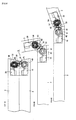
- FIG. 6 shows the opening and closing operation of the first housing 2 and the second housing 3 according to the above hinge device 5.
- the hinge device 5 portion is shown covered by a cosmetic cover 4 in FIG. 1.
- the schematic configuration of the hinge device 5 is shown in FIGS.
- FIG. 2A and 2B with a transparent view of cosmetic cover 4 and with the first housing 2 and the second housing 3 in a closed state.
- FIG. 2C shows the hinge device 5 with the transparent view of cosmetic cover 4 and with the first housing 2 and the second housing 3 in an opened state.
- the cellular telephone 1 is provided with the thin, flat first housing 2 and second housing 3, which can be folded together and unfolded via the hinge device 5.
- a keyboard is provided to the first housing 2
- a liquid-crystal display is provided to the second housing 3.
- the hinge device 5 is provided with a first installation frame 10 attached to the first housing 2, a second installation frame 20 attached to the second housing 3, and a third installation frame 30 that rotatably supports the installation frames 10, 20.
- the first installation frame 10 and the second installation frame 20 are built into respective recesses formed at the joining locations of the folding first housing 2 and second housing 3, respectively, and are not provided with any protruding parts.
- the third installation frame 30 rotatably supports the base-end sections (as viewed from the third installation frame 30) of the first installation frame 10 and the second installation frame 20 via a first main shaft 40 and a second main shaft 50 that are positioned in parallel (see FIG. 2C). According to this configuration, the head sections of the first installation frame 10 and the second installation frame 20 can rotate so as to approach or separate from one another.
- the third installation frame 30 also rotatably holds gears 81, 82, which are serially positioned between a gear 41 of the first main shaft 40 and a gear 51 of the second main shaft 50.
- the even-numbered gear train that is composed of the gear 41, the gear 81, the gear 82, and the gear 51 constitutes a rotation-force transmission mechanism 80.
- the hinge device 5 is also provided with a rotation-angle restriction means 60 that is composed of a cam and an extending spring 65 or the like (see FIG. 2A).
- FIG. 3A is a perspective view that shows the hinge device in a folded state.
- FIG. 3B is perspective view that shows the hinge device in an opened state.
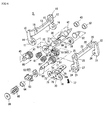
- FIG. 4 is a disassembled perspective view of the hinge device.
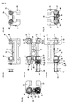
- FIG. 5 contains views of the hinge device of FIG. 3A viewed from the top, the front, the left, the right, and other perspectives.
- FIG. 5 shows the hinge device from different angles so as to be more readily understood.
- the first installation frame 10 is formed into an upside-down approximate U-shape from a metal plate or the like.
- the first installation frame 10 has symmetrical pairs of base-end sections 11 and head sections 12, as well as a linking part 13 that connects the head sections 12.
- a rectangular shaft hole 14 into which a D-cut part of the first main shaft 40 fits is provided to one of the base-end sections 11 (the base-end section 11 on the near side in FIG. 4, the same hereinafter), and a round shaft hole 16 into which the end of a first axle 42 fits is provided to the other base-end section 11 (the base-end section 11 on the far side in FIG. 4, the same hereinafter).
- Fixing holes 15 to which the housings attach are provided to the linking part 13. According to this configuration, applying a rotation force to the first installation frame 10 transmits that rotation force to the gear 41 of the first main shaft 40.
- the second installation frame 20 has symmetrical pairs of base-end sections 21 and head sections 22, as well as a linking part 23 that connects the head sections 22, as shown in FIG. 4.
- a large-diameter shaft hole 24, through which the second main shaft 50 passes, and a concave part 27, which engages with a coupling 63, are provided to one of the base-end sections 21, and a round shaft hole 26 into which the end of a second axle 52 fits is provided to the other base-end section 21.
- Fixing holes 25 to which the housings attach are provided to the linking part 23.
- the coupling 63 holds a cam follower 62 of the rotation-angle restriction means 60.
- the cam follower 62 is nonrotatably joined to the second main shaft 50. According to this configuration, applying a rotation force to the second installation frame 20 causes that rotation force to be transmitted to the gear 51 of the second main shaft 50.
- the third installation frame 30 is composed of an upper area 31, which is formed from a metal plate or the like, and a pair of lateral areas 32, 32, which are bent at right angles on the left and right ends of the upper area 31.
- a shaft hole 33 that rotatably supports the first main shaft 40, a shaft hole 34 that rotatably supports the second main shaft 50, shaft holes 35, 36 that rotatably support the gears 81, 82, and a cam surface 61 of the rotation-angle restriction means 60 are provided to one of the lateral areas 32.
- the shaft hole 35 and the shaft hole 36 are staggered between the shaft hole 33 and the shaft hole 34.
- a shaft hole 37, which supports the first axle 42, and a shaft hole 38, which supports the second axle 52, are provided to the other lateral area 32.
- a screw hole 39 for fixing a supplementary installation frame 70 and an aperture 31a to which the cover 4 attaches are provided to the upper area 31.
- the length of the upper area 31 regulates the pair of lateral areas 32, 32 of the third installation frame 30 so that the lateral areas 32, 32 are positioned between the pair of base-end sections 11, 11 of the first installation frame 10 and between the pair of base-end sections 21, 21 of the second installation frame 20.
- the rotation-angle restriction means 60 includes the cam surface 61 and the cam follower 62.
- the rotation-angle restriction means 60 is also provided with the coupling 63, a sleeve 64, the extension spring 65, and a lock washer 66 in order to elastically engage the cam follower 62 with the cam surface 61 and in order to couple the movement of the cam follower 62 to the rotation of the second installation frame 20.
- the assembly of the rotation-angle restriction means 60 involves first inserting the near-side shaft part of the second main shaft 50 into the shaft hole 34 of the third installation frame 30 and then fitting the cam follower 62, the coupling 63, and the sleeve 64 to this shaft part.
- the end of the shaft part is then passed through the large-diameter shaft hole 24 of the second installation frame 20, and the extension spring 65 is fit to the end of the shaft part.
- the extension spring 65 provides a pressing force to the cam follower 62 via the sleeve 64, which can move in the axial direction.
- the far-side shaft part of the second main shaft 50 is fit into a shaft hole 74 of the supplementary installation frame 70.
- the rotation-angle restriction means 60 functions to increase the load for initiating rotation. Once that load is exceeded, the load decreases, and the opened or closed state is stabilized. The folding and unfolding operation of the housings 2, 3 is thus provided with a snap-action.
- the supplementary installation frame 70 supports the gears 41, 81, 82, 51 between the supplementary installation frame 70 and the lateral area 32 on one side of the third installation frame 30.
- the supplementary installation frame 70 is therefore composed of an upper area 71 and a lateral area 72.
- a screw hole 79, through which a fixing screw 77 is inserted, and an aperture 70a, which corresponds to the aperture 31a, are provided to the upper area 71.
- a shaft hole 73 for rotatably supporting the first main shaft 40, a shaft hole 74 for rotatably supporting the second main shaft 50, and shaft holes 75, 76 for rotatably supporting the gears 81, 82 are provided to the lateral area 72.
- the other lateral area 32 (on the far side in FIG. 4) of the third installation frame 30 rotatably supports the other base-end sections 11, 21 (on the far side in FIG. 4) of the first installation frame 10 and the second installation frame 20 via the first and second axles 42, 52.
- Sleeves 43, 53 are fit onto the first and second axles 42, 52, respectively.
- the sleeves 43, 53 maintain a prescribed space between the other lateral area 32 of the third installation frame 30 and the other base-end sections 11, 21 of the first installation frame 10 and the second installation frame 20.
- a lateral surface of the cosmetic cover 4 passes through these empty spaces.
- the gears 41, 51 are fixed to the first and second main shafts 40, 50, respectively, and the gears 81, 82 are provided to be capable of rotation around central support shafts.
- the gear 41, the gear 81, the gear 82, and the gear 51 are configured as an even-numbered gear train.
- the rotation-force transmission mechanism 80 that is composed of this even-numbered gear train is provided between the first installation frame 10 and the second installation frame 20, and rotation force is applied to one of the first installation frame 10 or the second installation frame 20, the rotation-force transmission mechanism 80 functions to transmit a reverse rotation force to the other installation frame.
- the first main shaft 40 rotates, and the gear 41 rotates.
- the rotation of the gear 41 is transmitted to the gear 51 via the gears 81, 82.
- the gear 51 rotates
- the second main shaft 50 rotates.
- the cam follower 62 which is joined to the second main shaft 50, and the coupling 63 then rotate, and the second installation frame 20 that is engaged with the coupling 63 rotates.
- the cam follower 62 is elastically engaged with the cam surface 61, functioning as the rotation-angle restriction means 60. (See FIGS. 3 and 5.)
- FIGS. 6A through 6C show the operation of the hinge device 5 when the second housing 3 (the second installation frame 20) is opened relative to the first housing 2 (the first installation frame 10) from the closed state. It can be seen that the first housing 2 and the second housing 3 form a continuous, flat surface when opened.
- This opened state results from the fact that two shafts, i.e., the first main shaft 40 of the first installation frame 10 and the second main shaft 50 of the second installation frame 20, are both housed within respective recesses of the first housing 2 and the second housing 3 and are supported by the third installation frame 30.
- the gears 41, 51 of the two shafts are linked by the rotation-force transmission mechanism 80, which includes the gears 81, 82. Therefore, the diameter of the gears 41, 51 of the two shafts can be reduced, and the gears 41, 51 of the two shafts can be housed in the respective recesses of the first housing 2 and the second housing 3 without any protruding parts being provided.
- the first and second installation frames 10, 20 are axially supported by the third installation frame 30 via the first and second main shafts 40, 50.
- the first and second main shafts are linked by the rotation-force transmission mechanism 80, which transmits a reverse rotation force. Therefore, when, e.g., the first installation frame 10 rotates about the third installation frame 30 in one direction, the second installation frame 20 also rotates about the third installation frame 30 in the opposite direction, and the operation for opening the housings therefore proceeds smoothly. Furthermore, the rotation of the first installation frame 10 and the rotation of the second installation frame 20 are linked. Therefore, when the folding apparatus in the prior art is in the folded state, the positions of the housings will be offset if the two shafts are independent.
- the rotation-angle restriction means 60 is provided to the rotation-force transmission mechanism 80, and therefore a thin, flat, and continuous opened surface can be obtained, and a snap action can be obtained for the opening and closing operations of the housings 2, 3, as described above.
- the present invention is not limited to the configuration of the embodiment above, and the specific configuration may be designed as appropriate.
- the relationships between the first housing 2 and the second housing 3 and between the first installation frame 10 and the second installation frame 20 may be reversed from the description above.
- the rotation-angle restriction means 60 was provided to the second installation frame 20 in the example above, but the rotation-angle restriction means 60 may be provided to the first installation frame 10 or to both of the installation frames.
- the supplementary installation frame 70 was used in the embodiment described above, but the present invention can be implemented without the supplementary installation frame 70.
- the base-end sections of first and second installation frames which are stored in respective folding housings, are held by two parallel shafts via a third installation frame, and gears provided to these two shafts are linked by an even number of gears. Anything that has this basic configuration is included in the present invention.
Landscapes
- Engineering & Computer Science (AREA)
- Computer Hardware Design (AREA)
- General Engineering & Computer Science (AREA)
- Theoretical Computer Science (AREA)
- Physics & Mathematics (AREA)
- Human Computer Interaction (AREA)
- General Physics & Mathematics (AREA)
- Mechanical Engineering (AREA)
- Mathematical Physics (AREA)
- Signal Processing (AREA)
- Pivots And Pivotal Connections (AREA)
- Telephone Set Structure (AREA)
Abstract
Description
- The present invention relates to a hinge device that is attached to two housings and that can be closed when folded together. The present invention particularly relates to a hinge device that is ideal for a cellular phone, a notebook computer, or another folding electronic apparatus.
- Conventional hinge devices of this type involve providing a rotatable support member that supports a shaft to one of two housings and providing a bearing part that fits over the shaft to the other housing. The two housings are rotatably supported by one or two shafts (see, e.g.,
Patent Documents 1, 2). - [Patent Document 1]:
Japanese Laid-open Patent Application No. 2004-52892 - [Patent Document 2]:
Japanese Laid-open Patent Application No. 2004-308710 - The hinge device described in
Patent Document 1 has a configuration in which the two housings are rotatably held together by a single common support shaft. In this configuration, an arm part must protrude from one of the housings when the shaft part is provided within the other housing, or, alternatively, the shaft part will protrude when the shaft part is provided outside the housings. The arm part or the shaft part therefore protrudes when the housings are unfolded, and the opened surfaces protrude without forming a continuous, flat surface. In this regard, the hinge device described inPatent Document 2 supports the two housings using two shafts, and therefore the linking parts of the housings do not protrude and the opened surface is flat.
In this hinge device, however, a pair of hinge mechanisms, which are rotatably supported by the two shafts, operate independently with regard to a linking member, and the two housings therefore slide past one another when folded together. When both housings have the same shape, the housings may not overlap properly during folding, and one of the housings may be offset from the other housing.
This offset may feel unstable to the user and make the product appear to be defective. The housings must be slid together and overlaid in order to remedy the offset, forcing the user to perform extra operations. Since the two hinge mechanisms operate independently, one of the hinge mechanisms may hit the wall surface or other component of the frame, and the timing at which further rotation occurs will differ for each hinge mechanism; therefore, the opening and closing operations are inconsistent. One of the hinge mechanisms may hit a wall surface during the opening or closing operations. The user may experience an odd feeling when the rotation is impeded, and may not be able to be perform smooth opening and closing. - The present invention was devised in order to solve the problems inherent in such prior art, and it is an object thereof to provide a hinge device capable of a stable folding movement in which no displacement occurs, as well as to provide a folding electronic apparatus in which this hinge device is used.
- In order to achieve the above object, the present invention is a hinge device for folding and unfolding a first housing and a second housing, comprising a first installation frame installed on the first housing; a second installation frame installed on the second housing; a third installation frame for rotatably supporting a base-end section of each of the frames via a first main shaft and a second main shaft, which are arranged parallel to each other and to which rotation of the frames is transmitted, so that head section sides of the first installation frame and the second installation frame are rotatable in an approaching or separating direction; a rotation-force transmission mechanism for linking the first main shaft and the second main shaft and having a function of transmitting a reverse rotation force from one main shaft to the other; and a rotation-angle restriction means composed of a cam surface formed on the third installation frame and a cam follower that rotates integrally with at least one of the first main shaft and the second main shaft and that elastically engages with the cam surface. The first main shaft and the second main shaft are positioned within respective recesses formed at joining locations of the first housing and the second housing, which fold together, whereby an opened surface of the housings forms a continuous, approximately flat surface.
- The rotation-transmitting mechanism of the present invention comprises first and second gears provided to the first and second main shafts, and an even number of gears that are interposed between the first and second gears, wherein the first and second gears and the gears of even number are linked together and constitute a gear train.
- The gears of even number of the present invention are arranged on and secured to the third installation frame in a staggered, interlocked state, and the first and second gears have a smaller diameter than the gears of even number.
- According to the hinge device of the present invention, the first installation frame on the first housing side and the second installation frame on the second housing side are axially supported by the third installation frame via the first and second main shafts, and the first and second main shafts are linked by the rotation-force transmission mechanism for transmitting a reverse rotation force. Therefore, when, e.g., the first installation frame rotates about the third installation frame in one direction, the second installation frame also rotates about the third installation frame in the opposite direction, and the operation for opening the housings therefore proceeds smoothly. Furthermore, the rotation of the first installation frame and the rotation of the second installation frame are linked. Therefore, when the folding apparatus in the prior art is in the folded state, the positions of the housings will be offset if the two shafts are independent. However, such offset does not occur in the present invention because the two shafts are linked by the rotation-force transmission mechanism. In other words, if this hinge device is applied to, e.g., a folding cellular telephone, there will be no offset in the positions of the upper and lower housings thereof, and a sense of stability can be conveyed to the user.
Since the first and second main shafts are built into the interior of the respective first and second housings, the protrusions and cavities on the main shaft parts of the prior art are not present. The opened surface of the two housings can therefore be made into a continuous, flat surface. The first main shaft and the second main shaft are linked by a mechanism for transmitting reverse rotation force, and the rotation-angle restriction means is also present. The opened surface will accordingly be continuously flat, yielding a thin profile, and a snap action can be obtained for the folding and unfolding operations of the first housing and the second housing.
According to this invention, when one of the first or second installation frames is made to rotate, the other installation frame is made to rotate in the opposite direction, and the operation for opening the first and second housings can therefore be performed smoothly. The gears of even number are fixed in position on the third installation frame in a staggered, interlocked fashion, whereby the distance between the support shafts of the first and second gears can be shortened. The apparatus can therefore be made thinner. The first and second gears have small diameters, whereby protruding parts need not be provided to the first and second housings, and the first and second gears can be stored within recesses of the housings. -
- FIG. 1 is a partial schematic perspective view of a folding electronic apparatus provided with a hinge device according to an embodiment of the present invention;
- FIG. 2 shows the schematic configuration of the hinge device of the folding electronic apparatus according to the present embodiment, wherein FIG. 2A is plan view in which the housings are closed, FIG. 2B is a sectional side view in which the housings are closed, and FIG. 2C is a sectional side view in which the housings are open;
- FIG. 3A is a perspective view in which the above hinge device is closed;
- FIG. 3B is a perspective view in which the above hinge device is open;
- FIG. 4 is a disassembled perspective view of the above hinge device;
- FIG. 5 is a diagram that shows the same hinge device in third-angle projection, wherein FIG. 5A is a top view, FIG. 5B is a front view, FIG. 5C is a back view, FIG. 5D is a left-side view, FIG. 5E is a right-side view, and FIG. 5F is a view from the line VF-VF in FIG. 5B; and
- FIG. 6 is a diagram that shows the opening and closing operation of the first housing and the second housing according to the above hinge device, wherein FIG. 6A is a sectional view of the closed state, FIG. 6B is a sectional view of a partly opened state, and FIG. 6C is a sectional view of the open state.
-
- 1
- Folding electronic apparatus
- 2
- First housing
- 3
- Second housing
- 5
- Hinge device
- 10
- First installation frame
- 11
- Base-end section
- 12
- Head section
- 20
- Second installation frame
- 21
- Base-end section
- 22
- Head section
- 30
- Third installation frame
- 40
- First main shaft
- 41
- Gear of the first main shaft
- 50
- Second main shaft
- 51
- Gear of the second main shaft
- 60
- Rotation-angle restriction means
- 61
- Cam surface
- 62
- Cam follower
- 80
- Rotation-force transmission mechanism
- 81, 82
- Gear
- A hinge device according to an embodiment of the present invention and a folding electronic apparatus in which this hinge device is used will be described with reference to the drawings. FIGS. 1 and 2 show a folding electronic apparatus (a cellular telephone) 1 that has a
first housing 2 and asecond housing 3 capable of being folded together or unfolded, and that is provided with ahinge device 5 according to the present embodiment. FIGS. 3 through 5 show the detailed configuration of thehinge device 5, and FIG. 6 shows the opening and closing operation of thefirst housing 2 and thesecond housing 3 according to theabove hinge device 5. Thehinge device 5 portion is shown covered by acosmetic cover 4 in FIG. 1. The schematic configuration of thehinge device 5 is shown in FIGS. 2A and 2B with a transparent view ofcosmetic cover 4 and with thefirst housing 2 and thesecond housing 3 in a closed state. FIG. 2C shows thehinge device 5 with the transparent view ofcosmetic cover 4 and with thefirst housing 2 and thesecond housing 3 in an opened state. - As shown in FIG. 1, the
cellular telephone 1 is provided with the thin, flatfirst housing 2 andsecond housing 3, which can be folded together and unfolded via thehinge device 5. A keyboard is provided to thefirst housing 2, and a liquid-crystal display is provided to thesecond housing 3. As shown in FIG. 2, thehinge device 5 is provided with afirst installation frame 10 attached to thefirst housing 2, asecond installation frame 20 attached to thesecond housing 3, and athird installation frame 30 that rotatably supports the installation frames 10, 20.
Thefirst installation frame 10 and thesecond installation frame 20 are built into respective recesses formed at the joining locations of the foldingfirst housing 2 andsecond housing 3, respectively, and are not provided with any protruding parts. - The
third installation frame 30 rotatably supports the base-end sections (as viewed from the third installation frame 30) of thefirst installation frame 10 and thesecond installation frame 20 via a firstmain shaft 40 and a secondmain shaft 50 that are positioned in parallel (see FIG. 2C). According to this configuration, the head sections of thefirst installation frame 10 and thesecond installation frame 20 can rotate so as to approach or separate from one another. Thethird installation frame 30 also rotatably holds gears 81, 82, which are serially positioned between agear 41 of the firstmain shaft 40 and agear 51 of the secondmain shaft 50. The even-numbered gear train that is composed of thegear 41, thegear 81, thegear 82, and thegear 51 constitutes a rotation-force transmission mechanism 80. Thehinge device 5 is also provided with a rotation-angle restriction means 60 that is composed of a cam and an extendingspring 65 or the like (see FIG. 2A). - The details of the configuration of this
hinge device 5 will be described below with reference to FIGS. 3, 4, and 5. FIG. 3A is a perspective view that shows the hinge device in a folded state. FIG. 3B is perspective view that shows the hinge device in an opened state. FIG. 4 is a disassembled perspective view of the hinge device. FIG. 5 contains views of the hinge device of FIG. 3A viewed from the top, the front, the left, the right, and other perspectives. FIG. 5 shows the hinge device from different angles so as to be more readily understood.
As shown in FIG. 4, thefirst installation frame 10 is formed into an upside-down approximate U-shape from a metal plate or the like. Thefirst installation frame 10 has symmetrical pairs of base-end sections 11 andhead sections 12, as well as a linkingpart 13 that connects thehead sections 12. Arectangular shaft hole 14 into which a D-cut part of the firstmain shaft 40 fits is provided to one of the base-end sections 11 (the base-end section 11 on the near side in FIG. 4, the same hereinafter), and around shaft hole 16 into which the end of afirst axle 42 fits is provided to the other base-end section 11 (the base-end section 11 on the far side in FIG. 4, the same hereinafter). Fixingholes 15 to which the housings attach are provided to the linkingpart 13. According to this configuration, applying a rotation force to thefirst installation frame 10 transmits that rotation force to thegear 41 of the firstmain shaft 40. - As with the
first installation frame 10, thesecond installation frame 20 has symmetrical pairs of base-end sections 21 andhead sections 22, as well as a linkingpart 23 that connects thehead sections 22, as shown in FIG. 4. A large-diameter shaft hole 24, through which the secondmain shaft 50 passes, and aconcave part 27, which engages with acoupling 63, are provided to one of the base-end sections 21, and around shaft hole 26 into which the end of asecond axle 52 fits is provided to the other base-end section 21. Fixingholes 25 to which the housings attach are provided to the linkingpart 23. Thecoupling 63 holds acam follower 62 of the rotation-angle restriction means 60. Thecam follower 62 is nonrotatably joined to the secondmain shaft 50. According to this configuration, applying a rotation force to thesecond installation frame 20 causes that rotation force to be transmitted to thegear 51 of the secondmain shaft 50. - As shown in FIGS. 4 and 5, the
third installation frame 30 is composed of anupper area 31, which is formed from a metal plate or the like, and a pair oflateral areas upper area 31. Ashaft hole 33 that rotatably supports the firstmain shaft 40, ashaft hole 34 that rotatably supports the secondmain shaft 50, shaft holes 35, 36 that rotatably support thegears cam surface 61 of the rotation-angle restriction means 60 are provided to one of thelateral areas 32. Theshaft hole 35 and theshaft hole 36 are staggered between theshaft hole 33 and theshaft hole 34. According to this positioning, the distance between theshaft hole 33 and theshaft hole 34 can be reduced despite the use of thegears electronic apparatus 1 can be made thinner.
A shaft hole 37, which supports thefirst axle 42, and ashaft hole 38, which supports thesecond axle 52, are provided to the otherlateral area 32. Ascrew hole 39 for fixing asupplementary installation frame 70 and anaperture 31a to which thecover 4 attaches are provided to theupper area 31.
The length of theupper area 31 regulates the pair oflateral areas third installation frame 30 so that thelateral areas end sections first installation frame 10 and between the pair of base-end sections second installation frame 20. - As shown in FIGS. 4 and 5, the rotation-angle restriction means 60 includes the
cam surface 61 and thecam follower 62. The rotation-angle restriction means 60 is also provided with thecoupling 63, asleeve 64, theextension spring 65, and alock washer 66 in order to elastically engage thecam follower 62 with thecam surface 61 and in order to couple the movement of thecam follower 62 to the rotation of thesecond installation frame 20.
The assembly of the rotation-angle restriction means 60 involves first inserting the near-side shaft part of the secondmain shaft 50 into theshaft hole 34 of thethird installation frame 30 and then fitting thecam follower 62, thecoupling 63, and thesleeve 64 to this shaft part. The end of the shaft part is then passed through the large-diameter shaft hole 24 of thesecond installation frame 20, and theextension spring 65 is fit to the end of the shaft part. Theextension spring 65 provides a pressing force to thecam follower 62 via thesleeve 64, which can move in the axial direction. The far-side shaft part of the secondmain shaft 50 is fit into ashaft hole 74 of thesupplementary installation frame 70. - When the
first installation frame 10 and thesecond installation frame 20 rotate relative to one another during the process of moving from an opened or closed state to the other state, the rotation-angle restriction means 60 functions to increase the load for initiating rotation. Once that load is exceeded, the load decreases, and the opened or closed state is stabilized. The folding and unfolding operation of thehousings - As shown in FIGS. 4 and 5, the
supplementary installation frame 70 supports thegears supplementary installation frame 70 and thelateral area 32 on one side of thethird installation frame 30. Thesupplementary installation frame 70 is therefore composed of anupper area 71 and alateral area 72. Ascrew hole 79, through which a fixingscrew 77 is inserted, and anaperture 70a, which corresponds to theaperture 31a, are provided to theupper area 71. Ashaft hole 73 for rotatably supporting the firstmain shaft 40, ashaft hole 74 for rotatably supporting the secondmain shaft 50, and shaft holes 75, 76 for rotatably supporting thegears lateral area 72. - The other lateral area 32 (on the far side in FIG. 4) of the
third installation frame 30 rotatably supports the other base-end sections 11, 21 (on the far side in FIG. 4) of thefirst installation frame 10 and thesecond installation frame 20 via the first andsecond axles Sleeves second axles sleeves lateral area 32 of thethird installation frame 30 and the other base-end sections first installation frame 10 and thesecond installation frame 20. A lateral surface of thecosmetic cover 4 passes through these empty spaces. - With the rotation-
force transmission mechanism 80, thegears main shafts gears gear 41, thegear 81, thegear 82, and thegear 51 are configured as an even-numbered gear train. - When the rotation-
force transmission mechanism 80 that is composed of this even-numbered gear train is provided between thefirst installation frame 10 and thesecond installation frame 20, and rotation force is applied to one of thefirst installation frame 10 or thesecond installation frame 20, the rotation-force transmission mechanism 80 functions to transmit a reverse rotation force to the other installation frame. In other words, when rotation force is applied to thefirst installation frame 10, the firstmain shaft 40 rotates, and thegear 41 rotates. The rotation of thegear 41 is transmitted to thegear 51 via thegears gear 51 rotates, the secondmain shaft 50 rotates. Thecam follower 62, which is joined to the secondmain shaft 50, and thecoupling 63 then rotate, and thesecond installation frame 20 that is engaged with thecoupling 63 rotates. Thecam follower 62 is elastically engaged with thecam surface 61, functioning as the rotation-angle restriction means 60. (See FIGS. 3 and 5.) - FIGS. 6A through 6C show the operation of the
hinge device 5 when the second housing 3 (the second installation frame 20) is opened relative to the first housing 2 (the first installation frame 10) from the closed state. It can be seen that thefirst housing 2 and thesecond housing 3 form a continuous, flat surface when opened. This opened state results from the fact that two shafts, i.e., the firstmain shaft 40 of thefirst installation frame 10 and the secondmain shaft 50 of thesecond installation frame 20, are both housed within respective recesses of thefirst housing 2 and thesecond housing 3 and are supported by thethird installation frame 30. To be more specific, thegears force transmission mechanism 80, which includes thegears gears gears first housing 2 and thesecond housing 3 without any protruding parts being provided. - The first and second installation frames 10, 20 are axially supported by the
third installation frame 30 via the first and secondmain shafts force transmission mechanism 80, which transmits a reverse rotation force. Therefore, when, e.g., thefirst installation frame 10 rotates about thethird installation frame 30 in one direction, thesecond installation frame 20 also rotates about thethird installation frame 30 in the opposite direction, and the operation for opening the housings therefore proceeds smoothly. Furthermore, the rotation of thefirst installation frame 10 and the rotation of thesecond installation frame 20 are linked. Therefore, when the folding apparatus in the prior art is in the folded state, the positions of the housings will be offset if the two shafts are independent. However, such onset does not occur in this configuration because the two shafts are linked by the rotation-force transmission mechanism. In other words, there is no offset in the positions of the upper and lower housings of the cellular telephone, and a sense of stability can be conveyed to the user.
The rotation-angle restriction means 60 is provided to the rotation-force transmission mechanism 80, and therefore a thin, flat, and continuous opened surface can be obtained, and a snap action can be obtained for the opening and closing operations of thehousings - The present invention is not limited to the configuration of the embodiment above, and the specific configuration may be designed as appropriate. For example, the relationships between the
first housing 2 and thesecond housing 3 and between thefirst installation frame 10 and thesecond installation frame 20 may be reversed from the description above. The rotation-angle restriction means 60 was provided to thesecond installation frame 20 in the example above, but the rotation-angle restriction means 60 may be provided to thefirst installation frame 10 or to both of the installation frames. Thesupplementary installation frame 70 was used in the embodiment described above, but the present invention can be implemented without thesupplementary installation frame 70. In the basic configuration of the present invention, the base-end sections of first and second installation frames, which are stored in respective folding housings, are held by two parallel shafts via a third installation frame, and gears provided to these two shafts are linked by an even number of gears. Anything that has this basic configuration is included in the present invention.
Claims (3)
- A hinge device for folding and unfolding a first housing and a second housing, comprising:a first installation frame installed on the first housing;a second installation frame installed on the second housing;a third installation frame for rotatably supporting a base-end section of each of the frames via a first main shaft and a second main shaft, which are arranged parallel to each other and to which rotation of the frames is transmitted, so that head section sides of the first installation frame and the second installation frame are rotatable in an approaching or separating direction;a rotation-force transmission mechanism that links the first main shaft and the second main shaft and has a function of transmitting a reverse rotation force from one of the main shafts to the other; anda rotation-angle restriction means composed of a cam surface formed on the third installation frame and a cam follower that rotates integrally with at least one shaft selected from the first main shaft and the second main shaft and that elastically engages with the cam surface.
- The hinge device according to claim 1, wherein
the rotation-transmitting mechanism comprises first and second gears provided to the first and second main shafts; and
an even number of gears that are interposed between the first and second gears, wherein
the first and second gears and the gears of even number are linked together and constitute a gear train. - The hinge device according to claim 2, wherein the gears of even number are arranged on and secured to the third installation frame in a staggered, interlocked fashion.
Applications Claiming Priority (3)
| Application Number | Priority Date | Filing Date | Title |
|---|---|---|---|
| JP2005017124 | 2005-01-25 | ||
| JP2005292020A JP5170950B2 (en) | 2005-01-25 | 2005-10-05 | Hinge device |
| PCT/JP2006/301053 WO2006080308A1 (en) | 2005-01-25 | 2006-01-24 | Hinge device |
Publications (2)
| Publication Number | Publication Date |
|---|---|
| EP1843052A1 true EP1843052A1 (en) | 2007-10-10 |
| EP1843052A4 EP1843052A4 (en) | 2011-08-03 |
Family
ID=36740338
Family Applications (1)
| Application Number | Title | Priority Date | Filing Date |
|---|---|---|---|
| EP06712269A Withdrawn EP1843052A4 (en) | 2005-01-25 | 2006-01-24 | Hinge device |
Country Status (6)
| Country | Link |
|---|---|
| US (1) | US7765644B2 (en) |
| EP (1) | EP1843052A4 (en) |
| JP (1) | JP5170950B2 (en) |
| KR (1) | KR100995180B1 (en) |
| TW (1) | TWI345034B (en) |
| WO (1) | WO2006080308A1 (en) |
Cited By (2)
| Publication number | Priority date | Publication date | Assignee | Title |
|---|---|---|---|---|
| EP2584128A1 (en) * | 2011-10-19 | 2013-04-24 | Research In Motion Limited | Portable electronic device housing including hinge |
| US8711554B2 (en) | 2011-10-19 | 2014-04-29 | Blackberry Limited | Portable electronic device housing including hinge |
Families Citing this family (74)
| Publication number | Priority date | Publication date | Assignee | Title |
|---|---|---|---|---|
| TWI314036B (en) * | 2005-07-28 | 2009-08-21 | Sanyo Electric Co | Hinge mechanism of foldable machine and fordable machine with the same hinge mechanism |
| WO2007015461A1 (en) | 2005-08-02 | 2007-02-08 | Sanyo Electric Co., Ltd. | Folding apparatus |
| JP4326510B2 (en) * | 2005-08-02 | 2009-09-09 | 三洋電機株式会社 | Folding equipment |
| JP2007110346A (en) * | 2005-10-12 | 2007-04-26 | Omron Corp | Coupling mechanism and portable terminal |
| JP2007198416A (en) * | 2006-01-24 | 2007-08-09 | Strawberry Corporation | Hinge device, and electronic instrument using the same |
| US7832057B2 (en) * | 2006-10-05 | 2010-11-16 | The Hoffman Group International, Ltd. | Extendable multi-axis door hinge |
| US7805810B2 (en) * | 2006-10-05 | 2010-10-05 | Lawrence Andrew Hoffman | Multi leaf extendable gear hinge |
| JP5018294B2 (en) * | 2006-11-13 | 2012-09-05 | パナソニック株式会社 | Switchgear |
| US7832056B2 (en) * | 2006-11-13 | 2010-11-16 | Panasonic Corporation | Opening-closing device |
| KR200439610Y1 (en) * | 2007-02-14 | 2008-04-21 | (주) 프렉코 | Hinged cover switchgear for mobile terminal |
| KR100956302B1 (en) * | 2008-01-17 | 2010-05-10 | 주식회사 다이아벨 | terminal |
| TWI346275B (en) * | 2008-06-16 | 2011-08-01 | Asustek Comp Inc | Biaxial module and portable electronic apparatus having biaxial module |
| US8836611B2 (en) | 2008-09-08 | 2014-09-16 | Qualcomm Incorporated | Multi-panel device with configurable interface |
| US8863038B2 (en) | 2008-09-08 | 2014-10-14 | Qualcomm Incorporated | Multi-panel electronic device |
| US8860765B2 (en) | 2008-09-08 | 2014-10-14 | Qualcomm Incorporated | Mobile device with an inclinometer |
| US8947320B2 (en) | 2008-09-08 | 2015-02-03 | Qualcomm Incorporated | Method for indicating location and direction of a graphical user interface element |
| US8933874B2 (en) | 2008-09-08 | 2015-01-13 | Patrik N. Lundqvist | Multi-panel electronic device |
| US8803816B2 (en) | 2008-09-08 | 2014-08-12 | Qualcomm Incorporated | Multi-fold mobile device with configurable interface |
| US8860632B2 (en) | 2008-09-08 | 2014-10-14 | Qualcomm Incorporated | Multi-panel device with configurable interface |
| US9009984B2 (en) | 2008-09-08 | 2015-04-21 | Qualcomm Incorporated | Multi-panel electronic device |
| KR101027096B1 (en) * | 2009-06-01 | 2011-04-05 | 주식회사 팬택 | Hinge assembly and portable terminal having same |
| US20110265288A1 (en) * | 2010-04-29 | 2011-11-03 | Yung-Chang Chiang | Two-stage dual-pintle hinge |
| CN201771947U (en) * | 2010-05-10 | 2011-03-23 | 鸿富锦精密工业(深圳)有限公司 | Hinge structure |
| CN201779131U (en) * | 2010-05-27 | 2011-03-30 | 鸿富锦精密工业(深圳)有限公司 | Hinge structure |
| JP5864148B2 (en) * | 2010-07-12 | 2016-02-17 | 三菱製鋼株式会社 | Hinge device for electronic equipment |
| CN201874977U (en) * | 2010-08-18 | 2011-06-22 | 鸿富锦精密工业(深圳)有限公司 | Hinge structure |
| CN102454687B (en) * | 2010-10-26 | 2014-02-19 | 鸿富锦精密工业(深圳)有限公司 | Hinge structure |
| EP2546721B1 (en) * | 2011-07-11 | 2020-12-30 | Samsung Electronics Co., Ltd. | Flexible display with display support |
| TW201324091A (en) * | 2011-12-06 | 2013-06-16 | Compal Electronics Inc | Hinge mechanism and foldable electrinic device |
| US8578561B2 (en) * | 2012-01-19 | 2013-11-12 | Shin Zu Shing Co., Ltd. | Dual-axis hinge and portable device with the same |
| CN103291734A (en) * | 2012-02-28 | 2013-09-11 | 富泰华工业(深圳)有限公司 | Revolving mechanism and electronic equipment using same |
| KR101899502B1 (en) | 2012-05-31 | 2018-11-02 | 삼성전자주식회사 | Hinge device and computing apparatus having the same |
| TWI515385B (en) * | 2012-06-05 | 2016-01-01 | 緯創資通股份有限公司 | Adjustable supporting device |
| US9003606B2 (en) * | 2013-03-11 | 2015-04-14 | First Dome Corporation | Synchronous movement device applied to dual-shaft system |
| US8904601B2 (en) * | 2013-03-11 | 2014-12-09 | First Dome Corporation | Synchronous movement device applied to dual-shaft system |
| TWM466285U (en) * | 2013-03-27 | 2013-11-21 | First Dome Corp | Biaxial rotating shaft pivoted positioning structure |
| TWI508649B (en) * | 2013-05-10 | 2015-11-11 | Jarllytec Co Ltd | Two-way opening and closing of the connection device (a) |
| TWI547651B (en) * | 2013-06-05 | 2016-09-01 | 緯創資通股份有限公司 | Biaxial pivoting mechanism and portable electronic device thereof |
| US9310850B2 (en) * | 2013-06-11 | 2016-04-12 | First Dome Corporation | Synchronous movement device applied to dual-shaft system |
| TWI637669B (en) * | 2013-07-12 | 2018-10-01 | 易鼎股份有限公司 | Wearable assembly method of flexible circuit board and shaft member |
| US9182790B2 (en) * | 2013-10-15 | 2015-11-10 | Shin Zu Shing Co., Ltd. | Phase-locked pivot assembly |
| TWM476453U (en) * | 2013-12-06 | 2014-04-11 | Yuan Deng Metals Industrial Co Ltd | Synchronously-rotatable biaxial hinge |
| TWM478991U (en) * | 2013-12-17 | 2014-05-21 | First Dome Corp | Parallelism fixing device for dual rotary shaft |
| TWM483648U (en) * | 2013-12-31 | 2014-08-01 | First Dome Corp | Transmission-stabilizing device for dual rotation shaft |
| CN103783861B (en) * | 2014-01-22 | 2016-04-13 | 无锡豪思纺织品有限公司 | Faldstool |
| TWM483642U (en) * | 2014-02-25 | 2014-08-01 | First Dome Corp | Parallelism control device for dual shaft |
| US10975603B2 (en) | 2014-06-12 | 2021-04-13 | Microsoft Technology Licensing, Llc | Flexible display computing device |
| US9684343B2 (en) * | 2014-06-12 | 2017-06-20 | Microsoft Technology Licensing, Llc | Radius hinge |
| TWM498254U (en) * | 2014-09-26 | 2015-04-01 | First Dome Corp | Multi-section rotary shaft improved structure |
| US9442533B2 (en) * | 2014-12-30 | 2016-09-13 | Shin Zu Shing Co., Ltd. | Triaxial gear-typed hinge assembly and related electronic device |
| JP6105655B2 (en) * | 2015-03-06 | 2017-03-29 | レノボ・シンガポール・プライベート・リミテッド | Hinge device and portable information device |
| JP6493914B2 (en) * | 2015-03-13 | 2019-04-03 | 株式会社ナチュラレーザ・ワン | Multi-axis hinge and terminal device using this multi-axis hinge |
| US9816303B2 (en) * | 2016-03-16 | 2017-11-14 | Harry Kai Lee | Double axial hinge for a console |
| US10655383B2 (en) * | 2016-03-22 | 2020-05-19 | Olson Kundig, Inc. | System and method for implementing an improved bi-fold shutter |
| US9624704B1 (en) * | 2016-03-25 | 2017-04-18 | First Dome Corporation | Pivot pin device |
| KR102499448B1 (en) * | 2016-07-21 | 2023-02-15 | 삼성전자주식회사 | electronic device including hinge structure |
| US10208842B2 (en) * | 2016-09-06 | 2019-02-19 | Compal Electronics, Inc. | Linkage mechanism |
| EP3580417A4 (en) | 2017-02-13 | 2020-12-02 | Hewlett-Packard Development Company, L.P. | Friction hinges |
| US10088875B1 (en) * | 2017-07-10 | 2018-10-02 | Leohab Enterprises Co., Ltd. | 360° pivotal device for an electronic product |
| US10558245B2 (en) * | 2018-02-02 | 2020-02-11 | Dell Products L.P. | Information handling system narrow width hinge |
| WO2019194796A1 (en) * | 2018-04-04 | 2019-10-10 | Hewlett-Packard Development Company, L.P. | Dual-axis hinge assemblies |
| KR102167020B1 (en) | 2018-04-10 | 2020-10-16 | 주식회사 케이티앤지 | Rod Aerosol generating source supporting assembly and aerosol generating apparatus having the same |
| US11016541B2 (en) * | 2018-12-04 | 2021-05-25 | Compal Electronics, Inc. | Hinge assembly and electronic device using the same |
| US10983569B2 (en) * | 2018-12-07 | 2021-04-20 | Compal Electronics, Inc. | Hidden hinge and electronic device having the same |
| TWI691826B (en) * | 2019-01-08 | 2020-04-21 | 宏碁股份有限公司 | Electronic device and hinge mechanism of the same |
| US10880416B2 (en) | 2019-02-19 | 2020-12-29 | Htc Corporation | Foldable display device |
| CN113719522B (en) * | 2020-05-25 | 2022-10-18 | Oppo广东移动通信有限公司 | Rotating shaft assembly for folding electronic equipment, shell assembly and electronic equipment |
| US11720151B2 (en) | 2020-08-03 | 2023-08-08 | Microsoft Technology Licensing, Llc | Hinged device |
| US11505322B2 (en) * | 2020-10-05 | 2022-11-22 | B/E Aerospace, Inc. | Arm cap friction hinge mechanism |
| KR102382619B1 (en) * | 2021-03-31 | 2022-04-08 | 주식회사 에스코넥 | Hinge Apparatus |
| US11892883B2 (en) | 2021-04-19 | 2024-02-06 | Microsoft Technology Licensing, Llc | Display device with friction hinge |
| CN114078390B (en) * | 2021-11-15 | 2023-02-28 | 武汉华星光电半导体显示技术有限公司 | Folding display device |
| US12396112B2 (en) | 2021-12-31 | 2025-08-19 | Lg Display Co., Ltd. | Foldable display apparatus |
| CN118167731A (en) * | 2022-01-18 | 2024-06-11 | 荣耀终端有限公司 | Synchronous mechanism, rotating shaft mechanism and electronic equipment |
Family Cites Families (14)
| Publication number | Priority date | Publication date | Assignee | Title |
|---|---|---|---|---|
| US2206739A (en) * | 1938-06-08 | 1940-07-02 | Parsons Co | Concealed door hinge |
| US4765027A (en) * | 1986-06-30 | 1988-08-23 | Andric Milos D | Door hinge |
| KR920004386B1 (en) * | 1989-10-16 | 1992-06-04 | 현대전자산업 주식회사 | Key board cover and angle setting apparatus for laptop p.q. |
| US5666694A (en) * | 1995-09-28 | 1997-09-16 | Hewlett-Packard Company | Hinge arrangement |
| JPH09303032A (en) * | 1996-05-16 | 1997-11-25 | Kato Electrical Mach Co Ltd | Tilt hinge |
| TW454886U (en) * | 2000-10-04 | 2001-09-11 | Inventec Multimedia & Telecom | Pivot structure |
| JP4179408B2 (en) | 2002-07-19 | 2008-11-12 | 株式会社ストロベリーコーポレーション | HINGE DEVICE AND ELECTRONIC DEVICE USING HINGE DEVICE |
| EP1614913A4 (en) | 2003-04-03 | 2008-06-11 | Sugatsune Kogyo | Device case opening/closing device, and 2-axis hinge device |
| JP4090930B2 (en) * | 2003-04-03 | 2008-05-28 | スガツネ工業株式会社 | Device case opening and closing device |
| KR100640378B1 (en) * | 2003-04-30 | 2006-10-30 | 삼성전자주식회사 | One-step automatic hinge device and information terminal having the same |
| JP2005155750A (en) * | 2003-11-25 | 2005-06-16 | Konica Minolta Opto Inc | Folding type portable information terminal unit with imaging device |
| JP2006064000A (en) | 2004-08-24 | 2006-03-09 | Strawberry Corporation | Hinge device, and electronic device using hinge device |
| US7414834B2 (en) * | 2005-04-21 | 2008-08-19 | Nokia Corporation | Mobile communications device with synchronising hinge |
| KR100713480B1 (en) * | 2006-03-22 | 2007-05-02 | 삼성전자주식회사 | Hinge device of a portable terminal |
-
2005
- 2005-10-05 JP JP2005292020A patent/JP5170950B2/en not_active Expired - Fee Related
-
2006
- 2006-01-24 KR KR1020077017073A patent/KR100995180B1/en not_active Expired - Fee Related
- 2006-01-24 US US11/814,761 patent/US7765644B2/en not_active Expired - Fee Related
- 2006-01-24 EP EP06712269A patent/EP1843052A4/en not_active Withdrawn
- 2006-01-24 WO PCT/JP2006/301053 patent/WO2006080308A1/en not_active Ceased
- 2006-01-25 TW TW095102723A patent/TWI345034B/en not_active IP Right Cessation
Cited By (2)
| Publication number | Priority date | Publication date | Assignee | Title |
|---|---|---|---|---|
| EP2584128A1 (en) * | 2011-10-19 | 2013-04-24 | Research In Motion Limited | Portable electronic device housing including hinge |
| US8711554B2 (en) | 2011-10-19 | 2014-04-29 | Blackberry Limited | Portable electronic device housing including hinge |
Also Published As
| Publication number | Publication date |
|---|---|
| US20090013500A1 (en) | 2009-01-15 |
| KR100995180B1 (en) | 2010-11-17 |
| JP5170950B2 (en) | 2013-03-27 |
| JP2006234160A (en) | 2006-09-07 |
| WO2006080308A1 (en) | 2006-08-03 |
| KR20070103393A (en) | 2007-10-23 |
| TWI345034B (en) | 2011-07-11 |
| TW200639331A (en) | 2006-11-16 |
| HK1110105A1 (en) | 2008-07-04 |
| EP1843052A4 (en) | 2011-08-03 |
| US7765644B2 (en) | 2010-08-03 |
Similar Documents
| Publication | Publication Date | Title |
|---|---|---|
| US7765644B2 (en) | Hinge device | |
| KR101941584B1 (en) | Bending Hinge Apparatus and Electronic Device having it | |
| KR101912751B1 (en) | Bending Hinge Apparatus and Electronic Device having it | |
| KR101034912B1 (en) | Folding machine | |
| KR20050028776A (en) | Twist type mobile communication terminal and hinge device thereof | |
| EP1843053A1 (en) | Folding electronic apparatus | |
| CN120112727A (en) | Hinge assembly and foldable device | |
| CN101124414A (en) | hinge device | |
| WO2008140206A1 (en) | Sliding rotating apparatus | |
| JP4212577B2 (en) | Folding device hinge mechanism and folding device provided with this hinge mechanism | |
| CN101300539A (en) | Portable and hinged units | |
| US7096534B2 (en) | Hinge assembly with rotating mechanism | |
| JP4212578B2 (en) | Folding device hinge mechanism and folding device provided with this hinge mechanism | |
| CN117404386A (en) | Rotating shaft devices, folding casings and electronic equipment | |
| JP4381376B2 (en) | Folding electronics | |
| CN101233333B (en) | folding machine | |
| CN119496842B (en) | Foldable mechanisms and foldable terminals | |
| JP4660893B2 (en) | Switchgear | |
| JP2002039160A (en) | Hinge device | |
| CN118075384A (en) | Folding device, folding housing and electronic equipment | |
| CN119697299A (en) | Folding device, folding housing and electronic equipment | |
| JP2007040373A (en) | Foldable mobile phone | |
| CN119878694A (en) | Rotating shaft device, folding shell and electronic equipment | |
| CN119778371A (en) | Rotating shaft device, folding housing and electronic equipment | |
| CN118564547A (en) | Folding device, folding housing and electronic equipment |
Legal Events
| Date | Code | Title | Description |
|---|---|---|---|
| PUAI | Public reference made under article 153(3) epc to a published international application that has entered the european phase |
Free format text: ORIGINAL CODE: 0009012 |
|
| 17P | Request for examination filed |
Effective date: 20070720 |
|
| AK | Designated contracting states |
Kind code of ref document: A1 Designated state(s): DE FI GB |
|
| DAX | Request for extension of the european patent (deleted) | ||
| RBV | Designated contracting states (corrected) |
Designated state(s): DE FI GB |
|
| A4 | Supplementary search report drawn up and despatched |
Effective date: 20110704 |
|
| RIC1 | Information provided on ipc code assigned before grant |
Ipc: H04M 1/02 20060101AFI20110628BHEP Ipc: G06F 1/16 20060101ALI20110628BHEP Ipc: F16C 11/04 20060101ALI20110628BHEP Ipc: H05K 5/02 20060101ALI20110628BHEP Ipc: F16C 11/10 20060101ALI20110628BHEP |
|
| GRAP | Despatch of communication of intention to grant a patent |
Free format text: ORIGINAL CODE: EPIDOSNIGR1 |
|
| STAA | Information on the status of an ep patent application or granted ep patent |
Free format text: STATUS: THE APPLICATION IS DEEMED TO BE WITHDRAWN |
|
| 18D | Application deemed to be withdrawn |
Effective date: 20120915 |