EP1842704A1 - Transport refrigeration unit - Google Patents
Transport refrigeration unit Download PDFInfo
- Publication number
- EP1842704A1 EP1842704A1 EP07014836A EP07014836A EP1842704A1 EP 1842704 A1 EP1842704 A1 EP 1842704A1 EP 07014836 A EP07014836 A EP 07014836A EP 07014836 A EP07014836 A EP 07014836A EP 1842704 A1 EP1842704 A1 EP 1842704A1
- Authority
- EP
- European Patent Office
- Prior art keywords
- heat
- heat exchanger
- refrigeration unit
- axis
- accepting
- Prior art date
- Legal status (The legal status is an assumption and is not a legal conclusion. Google has not performed a legal analysis and makes no representation as to the accuracy of the status listed.)
- Granted
Links
Images

Classifications
-
- F—MECHANICAL ENGINEERING; LIGHTING; HEATING; WEAPONS; BLASTING
- F25—REFRIGERATION OR COOLING; COMBINED HEATING AND REFRIGERATION SYSTEMS; HEAT PUMP SYSTEMS; MANUFACTURE OR STORAGE OF ICE; LIQUEFACTION SOLIDIFICATION OF GASES
- F25D—REFRIGERATORS; COLD ROOMS; ICE-BOXES; COOLING OR FREEZING APPARATUS NOT OTHERWISE PROVIDED FOR
- F25D19/00—Arrangement or mounting of refrigeration units with respect to devices or objects to be refrigerated, e.g. infrared detectors
- F25D19/003—Arrangement or mounting of refrigeration units with respect to devices or objects to be refrigerated, e.g. infrared detectors with respect to movable containers
-
- B—PERFORMING OPERATIONS; TRANSPORTING
- B60—VEHICLES IN GENERAL
- B60H—ARRANGEMENTS OF HEATING, COOLING, VENTILATING OR OTHER AIR-TREATING DEVICES SPECIALLY ADAPTED FOR PASSENGER OR GOODS SPACES OF VEHICLES
- B60H1/00—Heating, cooling or ventilating devices
- B60H1/32—Cooling devices
- B60H1/3204—Cooling devices using compression
- B60H1/3232—Cooling devices using compression particularly adapted for load transporting vehicles
Definitions
- the present invention relates generally to a transport refrigeration unit for cooling a refrigerated container which includes a pair of transverse fans with substantially parallel axes that are driven by a simplified drive mechanism and which discharges air drawn through the condenser outside of the refrigeration unit.
- a transport refrigeration unit is typically utilized to cool a refrigerated container of a truck or trailer which transports refrigerated cargo, such as frozen food.
- the refrigeration unit is typically secured to the front wall of the truck or trailer at a main support frame.
- both axial and transverse fans are utilized to draw air through the evaporator and condenser.
- a complex drive system is utilized to drive the fans, increasing the complexity of the drive system.
- Air drawn through the evaporator in a prior transport refrigeration unit must also make a 180° turn from entry into the evaporator to exit into the refrigerated container. As the air is required to make several turns, there is additional friction and loss of energy, reducing the capacity of the refrigeration system.
- air drawn through the condenser is directed over the compressor which is located in the lower section of the refrigeration unit.
- the heated discharged air from the condenser which is cooler than the compressor, provides additional cooling of the compressor and drive package (motor and/or engine plus motor).
- An embodiment of a transport refrigeration unit of the present invention cools a refrigerated container which transports refrigerated goods, such as frozen foods. Air drawn through an inclined evaporator by a transverse fan is cooled and released at the top of the refrigerated container, cooling the cargo contained in the refrigerated container.
- the evaporator is angled approximately 25° to 45° from the trailer wall to increase the area of heat transfer.
- Air is drawn through the condenser by a larger transverse fan and discharged outside of the refrigeration unit in the direction of road airflow during forward vehicle movement.
- the condenser transverse fan is approximately 1.2 to 1.5 times the size of the evaporator transverse fan as there is a larger amount of air passing through the condenser.
- the axes of the heat exchanger transverse fans are substantially parallel to the axis of a motor shaft which drives the fans. As all the axes are substantially parallel, one continuous belt passing over the heat exchanger fans pulleys and the motor shaft pulley drives the fans, simplifying the drive mechanism of the refrigeration unit.
- the refrigeration unit further includes a partition including extensions located between the evaporator and the condenser to provide insulation.
- the extensions are positioned between the wall of the vehicle and the frame of the refrigeration unit to provide further insulation and preferably includes corrugations to further seal air flow.
- the present invention provides a transport refrigeration unit including a simplified drive system which drives a pair of heat exchanger fans.
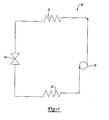
- FIG. 1 schematically illustrates a refrigeration cycle 20.
- the refrigeration cycle 20 consists of a compressor 22, a heat rejecting heat exchanger (a condenser) 24, an expansion device 26, and a heat accepting heat exchanger (an evaporator) 28.
- Refrigerant is circulated though the closed circuit refrigeration cycle 20.
- the refrigerant exits the compressor 22 at high pressure and enthalpy.
- the refrigerant cycle 20 is preferably included as part of a transport refrigeration unit 30, such as commonly utilized to cool a vehicle refrigerated container 32.
- transport refrigeration unit 30 are typically incorporated into refrigerated containers 32 carried by trucks or trailers, or other sources, to transport frozen goods such as frozen food.
- FIG. 2 illustrates the refrigeration unit 30 of the present invention.
- the refrigeration unit 30 is secured to the front wall 38 of the refrigerated container 32 at the main support frame 36 of the refrigeration unit 30.
- the refrigeration unit 30 further includes an evaporator compartment 40 and a condenser compartment 42 separated by a partition 44.
- the condenser compartment 42 includes the condenser 24, and the evaporator compartment 40 includes the inclined evaporator 28.
- the condenser 24 and the evaporator 28 are connected by a refrigeration line 46 containing the expansion device 26, completing the refrigeration cycle 20.
- the evaporator 28 is angled A degrees from the front wall 38 of the refrigerated container 32 to increase the area of heat transfer in the evaporator 28 without requiring additional space.
- the evaporator 28 is angled approximately 25° to 45° from the front wall 38 of the refrigerated container 32.
- the cooled air is drawn through the evaporator 28 by an evaporator transverse fan 50 and discharged at the top 52 of the refrigerated container 32 below the trailer ceiling 54 to cool the cargo in the refrigerated container 32.
- the air passing through the evaporator transverse fan 50 is naturally turned 90° by the fan 50.
- the air is turned naturally 90° by the evaporator transverse fan 50, the air only turns 90° in the refrigeration unit 30. As there are fewer turns during operation, friction and loss of energy is reduced, increasing capacity.
- the condenser transverse fan 58 is substantially larger than the evaporator transverse fan 50 as the air flow through the condenser 24 is greater than the air flow through the evaporator 28.
- the condenser transverse fan 58 is approximately 1.2 to 1.5 times the size of the evaporator transverse fan 50 to accommodate for the higher amount of air flowing through the condenser fan 58.
- the axes 60 and 62 of the heat exchanger fans 50 and 58, respectively, are substantially parallel to each other and to an axis 64 of an engine or motor shaft 66 which drives the fans 50 and 58.
- the heat exchanger fans 50 and 58 each include a pulley 80 and 82, respectively, and the motor shaft 66 includes a pulley 84.
- a continuous belt 68 passing over the pulleys 80, 82 and 84 drives the fans 50 and 58.
- the engine or motor shaft 66 is positioned in the lower portion of the refrigeration unit 30. As the motor shaft 66 operates, the belt 68 drives the fans 50 and 58, drawing air through the heat exchangers 24 and 28.
- the partition 44 includes a heat shield 70 and is positioned between the evaporator passageway 40 and the condenser passageway 42 to provide insulation.
- the partition 44 further includes extensions 72 extending between the trailer walls 38 and 54 and the frame 36 to provide additional insulation and prevent air from escaping between the walls 38 and 54 and the frame 36.
- the extensions 72 include a plurality of corrugations 74 which press into the trailer walls 38 and 54. The contact of the plurality of corrugations 74 with the walls 38 and 54 act as an additional seal, providing further insulation.
- the compressor 22 and drive package 90 increase in temperature.
- An additional axial fan 76 is positioned near the compressor 22 to cool the compressor 22 and the drive package 90. If an additionally axial fan 76 is utilized, a separate drive mechanism 78 is employed to drive the fan 76, shown schematically.
- the transport refrigeration unit 30 of the present invention there are several advantages. For one, as the axes 60 and 62 of the fans 50 and 58 are substantially parallel to the axis 64 of the motor shaft 66, one continuous belt 68 dries the fans 50 and 58, simplifying the drive mechanism. Additionally, by utilizing an evaporator transverse fan 50, the air makes fewer turns in the system 20 as the air is turned by the fan 50, reducing system losses and friction for air exiting the evaporator 24.
Landscapes
- Engineering & Computer Science (AREA)
- Physics & Mathematics (AREA)
- Thermal Sciences (AREA)
- Mechanical Engineering (AREA)
- Chemical & Material Sciences (AREA)
- Combustion & Propulsion (AREA)
- General Engineering & Computer Science (AREA)
- Devices That Are Associated With Refrigeration Equipment (AREA)
- Cold Air Circulating Systems And Constructional Details In Refrigerators (AREA)
- Crystals, And After-Treatments Of Crystals (AREA)
- Compression-Type Refrigeration Machines With Reversible Cycles (AREA)
Abstract
Description
- The present invention relates generally to a transport refrigeration unit for cooling a refrigerated container which includes a pair of transverse fans with substantially parallel axes that are driven by a simplified drive mechanism and which discharges air drawn through the condenser outside of the refrigeration unit.
- A transport refrigeration unit is typically utilized to cool a refrigerated container of a truck or trailer which transports refrigerated cargo, such as frozen food. The refrigeration unit is typically secured to the front wall of the truck or trailer at a main support frame. In a prior transport refrigeration unit, both axial and transverse fans are utilized to draw air through the evaporator and condenser. As the axes of the heat exchanger fans are not parallel, a complex drive system is utilized to drive the fans, increasing the complexity of the drive system.
- Air drawn through the evaporator in a prior transport refrigeration unit must also make a 180° turn from entry into the evaporator to exit into the refrigerated container. As the air is required to make several turns, there is additional friction and loss of energy, reducing the capacity of the refrigeration system.
- Additionally, in a prior transport refrigeration unit, air drawn through the condenser is directed over the compressor which is located in the lower section of the refrigeration unit. As the compressor heats during operation of the refrigeration unit, the heated discharged air from the condenser, which is cooler than the compressor, provides additional cooling of the compressor and drive package (motor and/or engine plus motor).
- An embodiment of a transport refrigeration unit of the present invention cools a refrigerated container which transports refrigerated goods, such as frozen foods. Air drawn through an inclined evaporator by a transverse fan is cooled and released at the top of the refrigerated container, cooling the cargo contained in the refrigerated container. Preferably, the evaporator is angled approximately 25° to 45° from the trailer wall to increase the area of heat transfer.
- Air is drawn through the condenser by a larger transverse fan and discharged outside of the refrigeration unit in the direction of road airflow during forward vehicle movement. Preferably, the condenser transverse fan is approximately 1.2 to 1.5 times the size of the evaporator transverse fan as there is a larger amount of air passing through the condenser.
- The axes of the heat exchanger transverse fans are substantially parallel to the axis of a motor shaft which drives the fans. As all the axes are substantially parallel, one continuous belt passing over the heat exchanger fans pulleys and the motor shaft pulley drives the fans, simplifying the drive mechanism of the refrigeration unit.
- The refrigeration unit further includes a partition including extensions located between the evaporator and the condenser to provide insulation. The extensions are positioned between the wall of the vehicle and the frame of the refrigeration unit to provide further insulation and preferably includes corrugations to further seal air flow.
- Accordingly, the present invention provides a transport refrigeration unit including a simplified drive system which drives a pair of heat exchanger fans.
- These and other features of the present invention will be best understood from the following specification and drawings.
- The various features and advantages of the invention will become apparent to those skilled in the art from the following detailed description of the currently preferred embodiment. The drawing that accompany the detailed description can be briefly described as follows:
- Figure 1 illustrates a schematic diagram of a refrigerant cycle; and
- Figure 2 illustrates the transport refrigeration unit of the present invention utilized to cool a refrigerated container.
- Figure 1 schematically illustrates a
refrigeration cycle 20. Therefrigeration cycle 20 consists of acompressor 22, a heat rejecting heat exchanger (a condenser) 24, anexpansion device 26, and a heat accepting heat exchanger (an evaporator) 28. - Refrigerant is circulated though the closed
circuit refrigeration cycle 20. The refrigerant exits thecompressor 22 at high pressure and enthalpy. As the refrigerant flows through thecondenser 24 at high pressure, it loses heat and enthalpy, exiting thecondenser 24 with low enthalpy and high pressure. As the refrigerant passes through theexpansion device 26, the pressure of the refrigerant drops. After expansion, the refrigerant passes through theevaporator 28 and exits at a high enthalpy and low pressure. The air passing through inside theevaporator 28 heats and evaporates the refrigerant. As the refrigerant absorbs heat from the air, the cooled air then circulates through therefrigerant container 32, thus cooling therefrigerant container 32 and its contents. After the refrigerant passes through thecompressor 22, it is again at high pressure and enthalpy, completing therefrigeration cycle 20. As shown schematically, therefrigerant cycle 20 is preferably included as part of atransport refrigeration unit 30, such as commonly utilized to cool a vehicle refrigeratedcontainer 32. As is known,such units 30 are typically incorporated into refrigeratedcontainers 32 carried by trucks or trailers, or other sources, to transport frozen goods such as frozen food. - Figure 2 illustrates the
refrigeration unit 30 of the present invention. Therefrigeration unit 30 is secured to thefront wall 38 of the refrigeratedcontainer 32 at themain support frame 36 of therefrigeration unit 30. Therefrigeration unit 30 further includes an evaporator compartment 40 and a condenser compartment 42 separated by a partition 44. The condenser compartment 42 includes thecondenser 24, and the evaporator compartment 40 includes theinclined evaporator 28. Thecondenser 24 and theevaporator 28 are connected by arefrigeration line 46 containing theexpansion device 26, completing therefrigeration cycle 20. - The
evaporator 28 is angled A degrees from thefront wall 38 of the refrigeratedcontainer 32 to increase the area of heat transfer in theevaporator 28 without requiring additional space. Preferably, theevaporator 28 is angled approximately 25° to 45° from thefront wall 38 of the refrigeratedcontainer 32. The cooled air is drawn through theevaporator 28 by an evaporatortransverse fan 50 and discharged at thetop 52 of the refrigeratedcontainer 32 below thetrailer ceiling 54 to cool the cargo in the refrigeratedcontainer 32. - The air passing through the evaporator
transverse fan 50 is naturally turned 90° by thefan 50. As the air is turned naturally 90° by the evaporatortransverse fan 50, the air only turns 90° in therefrigeration unit 30. As there are fewer turns during operation, friction and loss of energy is reduced, increasing capacity. - During operation, air is drawn upwardly through the
condenser 24 by a condensertransverse fan 58. The relatively warm air exits thecondenser 24 and therefrigeration unit 30 above thetrailer ceiling 54 in the same direction of road airflow during forward vehicle movement. Preferably, the condensertransverse fan 58 is substantially larger than the evaporatortransverse fan 50 as the air flow through thecondenser 24 is greater than the air flow through theevaporator 28. Most preferably, the condensertransverse fan 58 is approximately 1.2 to 1.5 times the size of the evaporatortransverse fan 50 to accommodate for the higher amount of air flowing through thecondenser fan 58. By employing a larger condensertransverse fan 58, the flow of air is maintained through therefrigeration cycle 20, minimizing wheel stress and retaining air speed. - The
axes heat exchanger fans axis 64 of an engine ormotor shaft 66 which drives thefans heat exchanger fans pulley 80 and 82, respectively, and themotor shaft 66 includes apulley 84. As theaxes continuous belt 68 passing over thepulleys fans motor shaft 66 is positioned in the lower portion of therefrigeration unit 30. As themotor shaft 66 operates, thebelt 68 drives thefans heat exchangers - The partition 44 includes a
heat shield 70 and is positioned between the evaporator passageway 40 and the condenser passageway 42 to provide insulation. The partition 44 further includesextensions 72 extending between thetrailer walls frame 36 to provide additional insulation and prevent air from escaping between thewalls frame 36. Preferably, theextensions 72 include a plurality ofcorrugations 74 which press into thetrailer walls corrugations 74 with thewalls - During operation of the
refrigeration unit 30, thecompressor 22 and drive package 90 (motor and/or engine plus radiator) increase in temperature. An additionalaxial fan 76 is positioned near thecompressor 22 to cool thecompressor 22 and thedrive package 90. If an additionallyaxial fan 76 is utilized, aseparate drive mechanism 78 is employed to drive thefan 76, shown schematically. - There are several advantages to the
transport refrigeration unit 30 of the present invention. For one, as theaxes fans axis 64 of themotor shaft 66, onecontinuous belt 68 dries thefans transverse fan 50, the air makes fewer turns in thesystem 20 as the air is turned by thefan 50, reducing system losses and friction for air exiting theevaporator 24. - The foregoing description is only exemplary of the principles of the invention. Many modifications and variations of the present invention are possible in light of the above teachings. The preferred embodiments of this invention have been disclosed, however, so that one of ordinary skill in the art would recognize that certain modifications would come within the scope of this invention. It is, therefore, to be understood that within the scope of the appended claims, the invention may be practiced otherwise than as specially described. For that reason the following claims should be studied to determine the true scope and content of this invention.
Claims (12)
- A refrigeration unit (30) comprising:a compressor (22), a heat rejecting heat exchanger (24), a heat accepting heat exchanger (28), and an expansion device (26) for circulating a refrigerant;a heat accepting transverse fan (50) having a first axis (60) to draw cooled air through said heat accepting heat exchanger (28) and into a refrigerated container (32); anda heat rejecting transverse fan (58) having a second axis (62) substantially parallel to said first axis (60) to draw air through said heat rejecting heat exchanger (24).
- The refrigeration unit as recited in claim 1 wherein said air is discharged from said heat rejecting heat exchanger (24) outside of said refrigeration unit (30).
- The refrigeration unit as recited in claim 1 or 2 wherein said refrigeration unit (30) further includes a motor shaft (66) having a third axis (64) substantially parallel to said first axis (60) and said second axis (62) to drive said fans (50,58).
- The refrigeration unit as recited in claim 3 wherein said heat accepting transverse fan (50) includes a first pulley (80), said heat rejecting transverse fan (58) includes a second pulley (82), and said motor shaft (66) includes a third pulley (84), operation of said motor shaft (66) driving said heat exchanger fans (50,58) by a continuous belt (68) positioned around said pulleys (80,82,84).
- A refrigeration unit (30) comprising:a compressor (22) to compress a refrigerant to a high pressure;a heat rejecting heat exchanger (24) for cooling said refrigerant;an expansion device (26) for reducing said refrigerant to a low pressure;a heat accepting heat exchanger (28) for evaporating said refrigerant;a refrigerated container (32) for being cooled by said heat accepting heat exchanger (28);a heat accepting transverse fan (50) having a first pulley (80) and first axis (60) to draw cooled air through said heat accepting heat exchanger (28) and into said refrigerated container (32); anda heat rejecting transverse fan (58) having a second pulley (82) and a second axis (62) to draw air through said heat rejecting heat exchanger (24) outside said refrigerated container (32);a motor (66) having a third pulley (84) and a third axis (64) to drive said fans (50,58), said first, second and third axes (60,62,64) being substantially parallel; anda continuous belt (68) positioned around said pulleys (80,82,84), operation of said motor (66) driving said heat exchanger fans (50,58) by said belt (68).
- The refrigeration unit as recited in any preceding claim wherein said heat rejecting transverse fan (58) is approximately 1.2 to 1.5 times the size of said heat accepting transverse fan (50).
- The refrigeration unit as recited in any preceding claim wherein a partition (44) separates said heat rejecting heat exchanger (24) and said heat accepting heat exchanger (28).
- The refrigeration unit as recited in claim 7 wherein said partition (44) includes at least one extension (72) positioned between a frame (36) of said refrigeration unit (30) and a wall (38) of a refrigerated container (32) to provide insulation.
- The refrigerated unit as recited in claim 8 wherein each of said extensions (72) includes a plurality of corrugations (74) which press into said wall (38) of said refrigerated container (30).
- The refrigeration unit as recited in any preceding claim wherein said heat accepting heat exchanger (28) is inclined approximately 25° to 45° from a trailer wall (32) of said refrigerated container (30).
- The refrigeration unit as recited in any preceding claim further including an axial fan (76) employed to cool said compressor (32) including a drive mechanism (78).
- A method for cooling a refrigerated container (30) with a refrigeration system comprising the steps of:(1) providing a refrigerant cycle (20) including a compressor (22), a heat accepting heat exchanger (28), an expansion device (26) and a heat rejecting heat exchanger (24);(2) drawing cooled air through said heat accepting heat exchanger (28) and into said refrigerated container (30) with a heat accepting transverse fan (50) having a first axis (60); and(3) drawing air through said heat rejecting heat exchanger (24) and outside of said refrigerated container (30) with a heat rejecting transverse fan (58) having a second axis (62) substantially parallel to said first axis (60); and(4) driving said transverse fans (50,58) with a drive mechanism.
Applications Claiming Priority (2)
| Application Number | Priority Date | Filing Date | Title |
|---|---|---|---|
| US10/005,100 US6543244B1 (en) | 2001-12-03 | 2001-12-03 | Transport refrigeration unit |
| EP02258146A EP1316454B1 (en) | 2001-12-03 | 2002-11-27 | Transport refrigeration unit |
Related Parent Applications (2)
| Application Number | Title | Priority Date | Filing Date |
|---|---|---|---|
| EP02258146.6 Division | 2002-11-27 | ||
| EP02258146A Division EP1316454B1 (en) | 2001-12-03 | 2002-11-27 | Transport refrigeration unit |
Publications (2)
| Publication Number | Publication Date |
|---|---|
| EP1842704A1 true EP1842704A1 (en) | 2007-10-10 |
| EP1842704B1 EP1842704B1 (en) | 2010-10-20 |
Family
ID=21714177
Family Applications (2)
| Application Number | Title | Priority Date | Filing Date |
|---|---|---|---|
| EP07014836A Expired - Lifetime EP1842704B1 (en) | 2001-12-03 | 2002-11-27 | Transport refrigeration unit |
| EP02258146A Expired - Lifetime EP1316454B1 (en) | 2001-12-03 | 2002-11-27 | Transport refrigeration unit |
Family Applications After (1)
| Application Number | Title | Priority Date | Filing Date |
|---|---|---|---|
| EP02258146A Expired - Lifetime EP1316454B1 (en) | 2001-12-03 | 2002-11-27 | Transport refrigeration unit |
Country Status (6)
| Country | Link |
|---|---|
| US (1) | US6543244B1 (en) |
| EP (2) | EP1842704B1 (en) |
| AT (2) | ATE485185T1 (en) |
| DE (2) | DE60222522T2 (en) |
| DK (2) | DK1316454T3 (en) |
| ES (1) | ES2292699T3 (en) |
Families Citing this family (8)
| Publication number | Priority date | Publication date | Assignee | Title |
|---|---|---|---|---|
| US6983619B2 (en) * | 2003-05-05 | 2006-01-10 | Carrier Corporation | Bus rooftop condenser fan |
| US20120031132A1 (en) * | 2009-05-25 | 2012-02-09 | Makoto Ikemiya | Trailer refrigerating apparatus |
| US9766009B2 (en) | 2011-07-07 | 2017-09-19 | Carrier Corporation | Method and system for transport container refrigeration control |
| EP2734285B1 (en) | 2011-07-18 | 2018-06-13 | Carrier Corporation | Scrubber system with moving adsorbent bed |
| CN103998879A (en) | 2011-12-20 | 2014-08-20 | 开利公司 | Components installed in an integrated refrigerated container |
| CN106949695A (en) * | 2012-03-22 | 2017-07-14 | B/E航空公司 | Vehicles refrigeration plant with steam circulation |
| EP2938517B1 (en) | 2012-12-31 | 2021-05-19 | Thermo King Corporation | Device and method for enhancing heat exchanger airflow |
| US20160280043A1 (en) * | 2015-03-25 | 2016-09-29 | Thermo King Corporation | Low profile refrigerated transport unit |
Citations (3)
| Publication number | Priority date | Publication date | Assignee | Title |
|---|---|---|---|---|
| US3404539A (en) | 1967-04-10 | 1968-10-08 | Laing Vortex Inc | Air conditioning apparatus |
| US4027498A (en) * | 1976-04-02 | 1977-06-07 | Mclean Engineering Midwest | Air conditioner |
| US4132088A (en) | 1975-12-27 | 1979-01-02 | Grosskopf Peter Volker | Refrigerating machine in flat unit construction |
Family Cites Families (9)
| Publication number | Priority date | Publication date | Assignee | Title |
|---|---|---|---|---|
| US3200609A (en) * | 1964-04-15 | 1965-08-17 | Laing Vortex Inc | Heat exchange apparatus and air conditioner units incorporating such apparatus |
| US3628350A (en) * | 1970-06-22 | 1971-12-21 | Samuel M Ruth | Wall air conditioner |
| US3729952A (en) * | 1971-09-09 | 1973-05-01 | Carrier Corp | Self-contained air conditioning unit |
| US3871188A (en) * | 1973-09-07 | 1975-03-18 | Thermo King Corp | Demountable transportation refrigeration unit |
| US4726197A (en) * | 1986-11-03 | 1988-02-23 | Megrditchian Dennis L | Apparatus for treating air |
| US5129235A (en) * | 1991-08-26 | 1992-07-14 | Thermo King Corporation | Compartmentalized transport refrigeration system |
| JPH05286352A (en) * | 1992-04-13 | 1993-11-02 | Mitsubishi Heavy Ind Ltd | Refrigerator for transportation |
| US5605055A (en) * | 1995-10-20 | 1997-02-25 | Carrier Corporation | Roof mounted air conditioner |
| US5916253A (en) | 1998-05-04 | 1999-06-29 | Carrier Corporation | Compact trailer refrigeration unit |
-
2001
- 2001-12-03 US US10/005,100 patent/US6543244B1/en not_active Expired - Lifetime
-
2002
- 2002-11-27 EP EP07014836A patent/EP1842704B1/en not_active Expired - Lifetime
- 2002-11-27 AT AT07014836T patent/ATE485185T1/en not_active IP Right Cessation
- 2002-11-27 DE DE60222522T patent/DE60222522T2/en not_active Expired - Lifetime
- 2002-11-27 AT AT02258146T patent/ATE373576T1/en not_active IP Right Cessation
- 2002-11-27 DE DE60238087T patent/DE60238087D1/en not_active Expired - Lifetime
- 2002-11-27 EP EP02258146A patent/EP1316454B1/en not_active Expired - Lifetime
- 2002-11-27 ES ES02258146T patent/ES2292699T3/en not_active Expired - Lifetime
- 2002-11-27 DK DK02258146T patent/DK1316454T3/en active
- 2002-11-27 DK DK07014836.6T patent/DK1842704T3/en active
Patent Citations (3)
| Publication number | Priority date | Publication date | Assignee | Title |
|---|---|---|---|---|
| US3404539A (en) | 1967-04-10 | 1968-10-08 | Laing Vortex Inc | Air conditioning apparatus |
| US4132088A (en) | 1975-12-27 | 1979-01-02 | Grosskopf Peter Volker | Refrigerating machine in flat unit construction |
| US4027498A (en) * | 1976-04-02 | 1977-06-07 | Mclean Engineering Midwest | Air conditioner |
Also Published As
| Publication number | Publication date |
|---|---|
| US6543244B1 (en) | 2003-04-08 |
| EP1316454A2 (en) | 2003-06-04 |
| EP1316454B1 (en) | 2007-09-19 |
| EP1842704B1 (en) | 2010-10-20 |
| DE60222522D1 (en) | 2007-10-31 |
| DK1316454T3 (en) | 2008-01-28 |
| ATE485185T1 (en) | 2010-11-15 |
| ATE373576T1 (en) | 2007-10-15 |
| DE60238087D1 (en) | 2010-12-02 |
| DE60222522T2 (en) | 2008-06-19 |
| DK1842704T3 (en) | 2011-02-14 |
| EP1316454A3 (en) | 2006-02-15 |
| ES2292699T3 (en) | 2008-03-16 |
Similar Documents
| Publication | Publication Date | Title |
|---|---|---|
| US6457324B2 (en) | Modular low-pressure delivery vehicle air conditioning system having an in-cab cool box | |
| US10710433B2 (en) | AC-system with very high cooling capacity | |
| JP6098121B2 (en) | Cooling system | |
| JP7120152B2 (en) | Air conditioner | |
| US20220026123A1 (en) | Integrated heating and cooling system and method for transportion refrigeration unit | |
| CN108603711A (en) | Conveying refrigerating plant | |
| US6543244B1 (en) | Transport refrigeration unit | |
| JP2023071628A (en) | Refrigeration cycle device for vehicle and on-vehicle apparatus control device | |
| CN118269588A (en) | A vehicle refrigerator capable of local rapid cooling | |
| EP2043885A1 (en) | Improved heating for a transport refrigeration unit operating in cold ambients | |
| EP3925806B1 (en) | Integrated cooling system and method for transportation refrigeration unit | |
| WO2018066276A1 (en) | Air-conditioning device for vehicle | |
| US20220088996A1 (en) | Refrigeration cycle device | |
| JPH10203148A (en) | Air-conditioner for electric vehicle | |
| US20240010049A1 (en) | Multi-compartment transport refrigeration system | |
| JPH1191433A (en) | Refrigerated motor-van | |
| JP2010076587A (en) | Cabin air-conditioner of transport vehicle | |
| JP2009210182A (en) | Refrigerating apparatus for vehicle | |
| JP2003214747A (en) | Refrigerated vehicle | |
| EP0652409A1 (en) | A refrigeration apparatus | |
| JP2003269835A (en) | Refrigeration unit for train container | |
| WO2022030182A1 (en) | Refrigeration cycle device | |
| US2102725A (en) | Refrigerator car | |
| KR100394595B1 (en) | Sub air conditioning equipment using ice accumulator for automobile | |
| KR200252627Y1 (en) | Cargo car having a versatile heat exchanger for heater and cooler |
Legal Events
| Date | Code | Title | Description |
|---|---|---|---|
| PUAI | Public reference made under article 153(3) epc to a published international application that has entered the european phase |
Free format text: ORIGINAL CODE: 0009012 |
|
| AC | Divisional application: reference to earlier application |
Ref document number: 1316454 Country of ref document: EP Kind code of ref document: P |
|
| AK | Designated contracting states |
Kind code of ref document: A1 Designated state(s): AT BE BG CH CY CZ DE DK EE ES FI FR GB GR IE IT LI LU MC NL PT SE SK TR |
|
| 17P | Request for examination filed |
Effective date: 20080403 |
|
| 17Q | First examination report despatched |
Effective date: 20080508 |
|
| AKX | Designation fees paid |
Designated state(s): AT BE BG CH CY CZ DE DK EE ES FI FR GB GR IE IT LI LU MC NL PT SE SK TR |
|
| GRAP | Despatch of communication of intention to grant a patent |
Free format text: ORIGINAL CODE: EPIDOSNIGR1 |
|
| GRAS | Grant fee paid |
Free format text: ORIGINAL CODE: EPIDOSNIGR3 |
|
| GRAA | (expected) grant |
Free format text: ORIGINAL CODE: 0009210 |
|
| AC | Divisional application: reference to earlier application |
Ref document number: 1316454 Country of ref document: EP Kind code of ref document: P |
|
| AK | Designated contracting states |
Kind code of ref document: B1 Designated state(s): AT BE BG CH CY CZ DE DK EE ES FI FR GB GR IE IT LI LU MC NL PT SE SK TR |
|
| REG | Reference to a national code |
Ref country code: GB Ref legal event code: FG4D |
|
| REG | Reference to a national code |
Ref country code: CH Ref legal event code: EP |
|
| REG | Reference to a national code |
Ref country code: IE Ref legal event code: FG4D |
|
| REF | Corresponds to: |
Ref document number: 60238087 Country of ref document: DE Date of ref document: 20101202 Kind code of ref document: P |
|
| PGFP | Annual fee paid to national office [announced via postgrant information from national office to epo] |
Ref country code: DK Payment date: 20101210 Year of fee payment: 9 |
|
| REG | Reference to a national code |
Ref country code: DK Ref legal event code: T3 |
|
| REG | Reference to a national code |
Ref country code: NL Ref legal event code: VDEP Effective date: 20101020 |
|
| PG25 | Lapsed in a contracting state [announced via postgrant information from national office to epo] |
Ref country code: FI Free format text: LAPSE BECAUSE OF FAILURE TO SUBMIT A TRANSLATION OF THE DESCRIPTION OR TO PAY THE FEE WITHIN THE PRESCRIBED TIME-LIMIT Effective date: 20101020 Ref country code: BG Free format text: LAPSE BECAUSE OF FAILURE TO SUBMIT A TRANSLATION OF THE DESCRIPTION OR TO PAY THE FEE WITHIN THE PRESCRIBED TIME-LIMIT Effective date: 20110120 Ref country code: PT Free format text: LAPSE BECAUSE OF FAILURE TO SUBMIT A TRANSLATION OF THE DESCRIPTION OR TO PAY THE FEE WITHIN THE PRESCRIBED TIME-LIMIT Effective date: 20110221 Ref country code: SE Free format text: LAPSE BECAUSE OF FAILURE TO SUBMIT A TRANSLATION OF THE DESCRIPTION OR TO PAY THE FEE WITHIN THE PRESCRIBED TIME-LIMIT Effective date: 20101020 Ref country code: NL Free format text: LAPSE BECAUSE OF FAILURE TO SUBMIT A TRANSLATION OF THE DESCRIPTION OR TO PAY THE FEE WITHIN THE PRESCRIBED TIME-LIMIT Effective date: 20101020 Ref country code: AT Free format text: LAPSE BECAUSE OF FAILURE TO SUBMIT A TRANSLATION OF THE DESCRIPTION OR TO PAY THE FEE WITHIN THE PRESCRIBED TIME-LIMIT Effective date: 20101020 |
|
| PG25 | Lapsed in a contracting state [announced via postgrant information from national office to epo] |
Ref country code: GR Free format text: LAPSE BECAUSE OF FAILURE TO SUBMIT A TRANSLATION OF THE DESCRIPTION OR TO PAY THE FEE WITHIN THE PRESCRIBED TIME-LIMIT Effective date: 20110121 Ref country code: MC Free format text: LAPSE BECAUSE OF NON-PAYMENT OF DUE FEES Effective date: 20101130 |
|
| REG | Reference to a national code |
Ref country code: CH Ref legal event code: PL |
|
| PG25 | Lapsed in a contracting state [announced via postgrant information from national office to epo] |
Ref country code: CH Free format text: LAPSE BECAUSE OF NON-PAYMENT OF DUE FEES Effective date: 20101130 Ref country code: EE Free format text: LAPSE BECAUSE OF FAILURE TO SUBMIT A TRANSLATION OF THE DESCRIPTION OR TO PAY THE FEE WITHIN THE PRESCRIBED TIME-LIMIT Effective date: 20101020 Ref country code: ES Free format text: LAPSE BECAUSE OF FAILURE TO SUBMIT A TRANSLATION OF THE DESCRIPTION OR TO PAY THE FEE WITHIN THE PRESCRIBED TIME-LIMIT Effective date: 20110131 Ref country code: CZ Free format text: LAPSE BECAUSE OF FAILURE TO SUBMIT A TRANSLATION OF THE DESCRIPTION OR TO PAY THE FEE WITHIN THE PRESCRIBED TIME-LIMIT Effective date: 20101020 Ref country code: LI Free format text: LAPSE BECAUSE OF NON-PAYMENT OF DUE FEES Effective date: 20101130 |
|
| PGFP | Annual fee paid to national office [announced via postgrant information from national office to epo] |
Ref country code: BE Payment date: 20110217 Year of fee payment: 9 |
|
| PLBE | No opposition filed within time limit |
Free format text: ORIGINAL CODE: 0009261 |
|
| STAA | Information on the status of an ep patent application or granted ep patent |
Free format text: STATUS: NO OPPOSITION FILED WITHIN TIME LIMIT |
|
| PG25 | Lapsed in a contracting state [announced via postgrant information from national office to epo] |
Ref country code: SK Free format text: LAPSE BECAUSE OF FAILURE TO SUBMIT A TRANSLATION OF THE DESCRIPTION OR TO PAY THE FEE WITHIN THE PRESCRIBED TIME-LIMIT Effective date: 20101020 |
|
| 26N | No opposition filed |
Effective date: 20110721 |
|
| GBPC | Gb: european patent ceased through non-payment of renewal fee |
Effective date: 20110120 |
|
| PG25 | Lapsed in a contracting state [announced via postgrant information from national office to epo] |
Ref country code: IE Free format text: LAPSE BECAUSE OF NON-PAYMENT OF DUE FEES Effective date: 20101127 |
|
| REG | Reference to a national code |
Ref country code: DE Ref legal event code: R097 Ref document number: 60238087 Country of ref document: DE Effective date: 20110721 |
|
| PG25 | Lapsed in a contracting state [announced via postgrant information from national office to epo] |
Ref country code: GB Free format text: LAPSE BECAUSE OF NON-PAYMENT OF DUE FEES Effective date: 20110120 |
|
| PG25 | Lapsed in a contracting state [announced via postgrant information from national office to epo] |
Ref country code: IT Free format text: LAPSE BECAUSE OF FAILURE TO SUBMIT A TRANSLATION OF THE DESCRIPTION OR TO PAY THE FEE WITHIN THE PRESCRIBED TIME-LIMIT Effective date: 20101020 |
|
| BERE | Be: lapsed |
Owner name: CARRIER CORP. Effective date: 20111130 |
|
| REG | Reference to a national code |
Ref country code: DK Ref legal event code: EBP |
|
| PG25 | Lapsed in a contracting state [announced via postgrant information from national office to epo] |
Ref country code: BE Free format text: LAPSE BECAUSE OF NON-PAYMENT OF DUE FEES Effective date: 20111130 Ref country code: CY Free format text: LAPSE BECAUSE OF FAILURE TO SUBMIT A TRANSLATION OF THE DESCRIPTION OR TO PAY THE FEE WITHIN THE PRESCRIBED TIME-LIMIT Effective date: 20101020 |
|
| PG25 | Lapsed in a contracting state [announced via postgrant information from national office to epo] |
Ref country code: LU Free format text: LAPSE BECAUSE OF NON-PAYMENT OF DUE FEES Effective date: 20101127 |
|
| PG25 | Lapsed in a contracting state [announced via postgrant information from national office to epo] |
Ref country code: DK Free format text: LAPSE BECAUSE OF NON-PAYMENT OF DUE FEES Effective date: 20111130 Ref country code: TR Free format text: LAPSE BECAUSE OF FAILURE TO SUBMIT A TRANSLATION OF THE DESCRIPTION OR TO PAY THE FEE WITHIN THE PRESCRIBED TIME-LIMIT Effective date: 20101020 |
|
| PGFP | Annual fee paid to national office [announced via postgrant information from national office to epo] |
Ref country code: FR Payment date: 20121130 Year of fee payment: 11 Ref country code: DE Payment date: 20121121 Year of fee payment: 11 |
|
| REG | Reference to a national code |
Ref country code: FR Ref legal event code: ST Effective date: 20140731 |
|
| PG25 | Lapsed in a contracting state [announced via postgrant information from national office to epo] |
Ref country code: DE Free format text: LAPSE BECAUSE OF NON-PAYMENT OF DUE FEES Effective date: 20140603 |
|
| REG | Reference to a national code |
Ref country code: DE Ref legal event code: R119 Ref document number: 60238087 Country of ref document: DE Effective date: 20140603 |
|
| PG25 | Lapsed in a contracting state [announced via postgrant information from national office to epo] |
Ref country code: FR Free format text: LAPSE BECAUSE OF NON-PAYMENT OF DUE FEES Effective date: 20131202 |