EP1842676A2 - Printhead and inkjet printer comprising such a printhead - Google Patents
Printhead and inkjet printer comprising such a printhead Download PDFInfo
- Publication number
- EP1842676A2 EP1842676A2 EP07104563A EP07104563A EP1842676A2 EP 1842676 A2 EP1842676 A2 EP 1842676A2 EP 07104563 A EP07104563 A EP 07104563A EP 07104563 A EP07104563 A EP 07104563A EP 1842676 A2 EP1842676 A2 EP 1842676A2
- Authority
- EP
- European Patent Office
- Prior art keywords
- wall
- converter
- printhead
- printhead according
- foregoing
- Prior art date
- Legal status (The legal status is an assumption and is not a legal conclusion. Google has not performed a legal analysis and makes no representation as to the accuracy of the status listed.)
- Withdrawn
Links
Images
Classifications
-
- B—PERFORMING OPERATIONS; TRANSPORTING
- B41—PRINTING; LINING MACHINES; TYPEWRITERS; STAMPS
- B41J—TYPEWRITERS; SELECTIVE PRINTING MECHANISMS, i.e. MECHANISMS PRINTING OTHERWISE THAN FROM A FORME; CORRECTION OF TYPOGRAPHICAL ERRORS
- B41J2/00—Typewriters or selective printing mechanisms characterised by the printing or marking process for which they are designed
- B41J2/005—Typewriters or selective printing mechanisms characterised by the printing or marking process for which they are designed characterised by bringing liquid or particles selectively into contact with a printing material
- B41J2/01—Ink jet
- B41J2/135—Nozzles
- B41J2/14—Structure thereof only for on-demand ink jet heads
- B41J2/14201—Structure of print heads with piezoelectric elements
- B41J2/14233—Structure of print heads with piezoelectric elements of film type, deformed by bending and disposed on a diaphragm
Definitions
- the invention relates to a printhead comprising multiple substantially closed ink chambers, the ink chambers being mutually separated by at least one deformable wall, wherein each of the chambers comprises an electro-mechanical converter, where actuation of the converter leads to a volume change of the corresponding chamber.
- the invention also relates to an inkjet printer comprising such a printhead.
- a printhead of this kind is known from American patent 5,617,127 .
- This printhead comprises one or more ink chambers substantially entirely defined by an integral ceramic substrate, in which the rigidity of the ceramic substrate is very high to prevent deformation of the walls.
- the ceramic substrate comprises a closure plate on top of which one or more bimorph actuators are applied, where actuation of the actuators leads to a volume change of the corresponding ink chamber(s).
- a major drawback of the known printhead is that relatively high voltages are required to actuate to the actuators to cause a volume change of the ink chambers, which makes the known printhead relatively energy-consuming, and hence relatively inefficient.
- It is an object of the invention is to provide a relatively efficient printhead.
- This object can be achieved by providing a printhead according to the preamble, characterized in that the wall and the converter are adapted for mutual cooperation, such that, based on that cooperation, actuation of the converter of an ink chamber leads to buckling of the converter. Actuation of the converter will elastically bend (a part of) the deformable wall outwardly, which will lead to the converter to buckle upwardly, thereby (temporarily) increasing the volume of the ink chamber. It has been found that this (reversible) buckling effect of the converter increases the efficiency of the converter, and hence of the functioning of the printhead according to the invention, significantly.
- a further advantage of the printhead is that the wall(s) will be deformed partially upon actuation of the converter. By allowing merely a (substantial) partial, and preferably a (location) selective deformation of the wall, cross-talk between adjacent ink chambers can be counteracted in a relatively efficient and satisfying manner.
- the wall thereby comprises a first wall side (partially) defining a first chamber and a second wall side opposite to the first wall side, said second wall side (partially) defining a second, neighbouring chamber, wherein the wall is deformable, such that actuation of the converter of the first chamber leads to a deformation of the wall, wherein the deformation of the first wall side is substantially larger than the deformation of the second wall side.
- the deformation behaviour of the wall can be optimised for the printhead to allow substantially merely a partial deformation upon actuation of the converter, it is recognized that it will often not be possible to prevent actuation of a converter to produce a (slight) volume change in an adjacent chamber.
- the wall is shaped substantially tapered.
- the first wall side and the second wall side of the wall are oriented in a non-parallel orientation with respect to each other. This leads to an improved storage capacity of elastic energy within the wall and to an advantageous wall deformation and to an efficient buckling of the converter upon actuation of the converter.
- the wall is made of a material having a Young's modulus (E modulus) smaller than 60 GPa, preferably less than 30 GPa en more preferably around 10 GPa.
- E modulus Young's modulus
- the wall between adjacent ink chambers is made from a relatively easily deformable (elastic) material with a relatively good shape recovery ability. This means that the wall can be made relatively thick without restrictions in deformability arising. An allowed robustness of the walls facilitates a less critical and a relatively simple manufacturing of the printhead according to the invention.
- the wall can be made of materials of various nature, the wall is preferably made at least partially from at least one material selected from the following group of materials: carbon, ceramics, and polymer, in particular an elastomer. Carbon combines the special advantages of low rigidity, typically 14 GPa, and good machinability, so that it is relatively simple to form the elements (channel plates) in which the chambers and walls are joined. In case the wall (or any other part of the printhead) is made of multiple materials, preferably materials are used which have or more or less similar coefficient of thermal expansion.
- the printhead comprises a carrier plate provided with the at least one wall, wherein the carrier plate and the at least one wall are made of substantial similar materials.
- the chambers and walls may easily be made by milling the chambers from a carbon element, which automatically produces a carbon wall between the chambers.
- the wall thickness and height requirements may be determined based on experiments or a model that may be applied in accordance with the present invention.
- the electro-mechanical converter comprises at least one piezo-electric element.
- the piezo-electric element comprises a (relatively thin) single layer piezo-electric layer of between 10 and 30 micrometer which require relatively low electric actuation voltages of less than 40 volt.
- the electro-mechanical converter is preferably provided with a protective layer.
- This protective layer is preferably made of a thin foil (film) made of metal or a polymer, in particular polyamide. The thickness of the protective foil may vary from several micrometers up to 30 micrometer. However, it is also conceivable to apply a multi layer piezo-electric element, which multiple piezo-electric layers are present.
- the invention also relates to an inkjet printer comprising at least one printhead as described above.
- a printhead may be applied without producing undesirable print artefacts in a printed image.
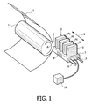
- Figure 1 is a diagram showing an inkjet printer.
- the printer comprises a roller 1 used to support a receiving medium 2, such as a sheet of paper or a transparency, and move it along the carriage 3.
- This carriage 3 comprises a carrier 5 to which four printheads 4a, 4b, 4c and 4d have been fitted.
- Each printhead 4a, 4b, 4c, 4d contains its own colour, in this case cyan (C), magenta (M), yellow (Y) and black (K) respectively.
- the printheads 4a, 4b, 4c, 4d are heated using heating elements 9, which have been fitted to the rear of each printhead 4a, 4b, 4c, 4d and to the carrier 5.
- the temperature of the printheads 4a, 4b, 4c, 4d is maintained at the correct level by application of a central control unit 10 (controller).
- the roller 1 may rotate around its own axis as indicated by arrow A.
- the receiving medium may be moved in the sub-scanning direction (often referred to as the X direction) relative to the carrier 5, and therefore also relative to the printheads 4a, 4b, 4c, 4d.
- the carriage 3 may be moved in reciprocation using suitable drive mechanisms (not shown) in a direction indicated by double arrow B, parallel to roller 1.
- the carrier 5 is moved across the guide rods 6 and 7. This direction is generally referred to as the main scanning direction or Y direction.
- each printhead 4a, 4b, 4c, 4d comprises a number of internal ink chambers (not shown), each with its own exit opening (nozzle) 8.
- the nozzles 8 in this embodiment form one row per printhead perpendicular to the axis of roller 1 (i.e. the row extends in the sub-scanning direction).
- the number of ink chambers per printhead will be many times greater and the nozzles 8 will be arranged over two or more rows.
- Each ink chamber comprises a piezo-electric converter (not shown) that may generate a pressure wave in the ink chamber so that an ink drop is ejected from the nozzle of the associated chamber in the direction of the receiving medium 2.
- the converters may be actuated image-wise via an associated electrical drive circuit (not shown) by application of the central control unit 10. In this manner, an image made up of ink drops may be formed on receiving medium 2. If a receiving medium 2 is printed using such a printer where ink drops are ejected from ink chambers, this receiving medium 2, or some of it, is imaginarily split into fixed locations that form a regular field of pixel rows and pixel columns. According to one embodiment, the pixel rows are perpendicular to the pixel columns.
- the individual locations thus produced may each be provided with one or more ink drops.
- the number of locations per unit of length in the directions parallel to the pixel rows and pixel columns is referred to as the resolution of the printed image, for example indicated as 400x600 d.p.i. ("dots per inch").
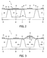
- FIG. 2 shows a cross-section of a printhead 4 according to the invention as used in the inkjet printer according to figure 1.
- the printhead 4 comprises a base structure 11 provided with multiple tapered walls 12 to define multiple ink chambers 13.
- the ink chambers 13 are closed by a compliant foil 14 onto which electro-mechanical converters 15 have been placed.
- Each converter 15 thereby comprises a single layer piezo-electric (generally applied PZT material) element with a thickness P of between 1 and 20 micrometer.
- the compliant foil 14 is in this embodiment a 10 micrometer thick Upilex polyamide foil (E modulus 9 GPa).
- the ink chambers 13 shown have a (minimum) width I of 100 micrometer and a height H of 100 micrometer.
- the ink chambers 13 are milled into the 2 mm thick carbon base structure 11, thereby generating the tapered separation walls 12 having a maximum width W of 69 micrometer. As these walls are made from carbon, they may reversibly deform in a direction substantially parallel to directions C as indicated.
- the chosen thickness W, together with the wall configuration as a component of the base structure 11 mean that they deform relatively easily, if the pressure inside a chamber changes.
- the deformable separation walls 12 and the converter(s) 15 are adapted to cooperate, such that actuation of a converter 15 of an ink chamber 13 leads to buckling of the converter 15 (see figure 3).
- the walls 12 are designed such that substantially merely a partial deformation will occur upon actuation of the piezo-electric converter 15. This partial deformation will not lead to a (noticeable) volume change in an adjacent ink chamber 13 upon actuation of the piezo-electric converter 15, as will be elucidated further hereinafter.
- Each ink chamber 13 is provided with a nozzle 16 for discharging ink contained within said chamber 13 upon actuation of the converter 15.
- FIG 3 schematically shows a cross-section of the printhead 4 according to figure 2 during operation.
- One of the converters 15 is actuated in the shown embodiment of the printhead 4 by applying a relatively low voltage of e.g. 7 Volt to said converter 15, as a result of which said converter 15 is (temporarily) buckled upwardly (see arrow D) thereby increasing the volume of the corresponding ink chamber 13.
- the direction of the deformation of the converter 15 is forced by the shape and material of the tapered walls 12.
- each tapered wall 12 (partially) defining the chamber 13 is deformed partially and location selectively, such that an adjacent chamber 13 is not subjected to a (considerable) net volume change.
- each wall 12 (partially) defining the ink chamber 13 is substantially deformed, while an opposite (second) wall side 12b of each wall 12 (partially) defining a neighbouring ink chamber 13 is not subjected to substantial deformation, as a result of which cross-talk between adjacent chambers 13 of the printhead 4 can be prevented, or at least forced back considerably, in a relatively efficient manner.
Landscapes
- Particle Formation And Scattering Control In Inkjet Printers (AREA)
Abstract
Description
- The invention relates to a printhead comprising multiple substantially closed ink chambers, the ink chambers being mutually separated by at least one deformable wall, wherein each of the chambers comprises an electro-mechanical converter, where actuation of the converter leads to a volume change of the corresponding chamber. The invention also relates to an inkjet printer comprising such a printhead.
- A printhead of this kind is known from
American patent 5,617,127 . This printhead comprises one or more ink chambers substantially entirely defined by an integral ceramic substrate, in which the rigidity of the ceramic substrate is very high to prevent deformation of the walls. The ceramic substrate comprises a closure plate on top of which one or more bimorph actuators are applied, where actuation of the actuators leads to a volume change of the corresponding ink chamber(s). A major drawback of the known printhead is that relatively high voltages are required to actuate to the actuators to cause a volume change of the ink chambers, which makes the known printhead relatively energy-consuming, and hence relatively inefficient. - It is an object of the invention is to provide a relatively efficient printhead.
This object can be achieved by providing a printhead according to the preamble, characterized in that the wall and the converter are adapted for mutual cooperation, such that, based on that cooperation, actuation of the converter of an ink chamber leads to buckling of the converter. Actuation of the converter will elastically bend (a part of) the deformable wall outwardly, which will lead to the converter to buckle upwardly, thereby (temporarily) increasing the volume of the ink chamber. It has been found that this (reversible) buckling effect of the converter increases the efficiency of the converter, and hence of the functioning of the printhead according to the invention, significantly. More in particular, due to this buckling effect the presence of a relatively thick passive (inert) intermediate layer, such as a conventional (ceramic) closure plate, onto which the converter is superposed is no longer required and can therefore be omitted. Omission, or at least reduction of the thickness of a conventional passive layer will result in that merely a relatively low voltage of less than 10 Volt is required to actuate the converter in a satisfying manner to cause a controlled volume change of the ink chamber(s). - Applying relatively low voltages to actuate the converter therefore leads to a relatively energy-saving, and hence a relatively efficient printhead for an inkjet printer. A further advantage of the printhead is that the wall(s) will be deformed partially upon actuation of the converter. By allowing merely a (substantial) partial, and preferably a (location) selective deformation of the wall, cross-talk between adjacent ink chambers can be counteracted in a relatively efficient and satisfying manner. More preferably, the wall thereby comprises a first wall side (partially) defining a first chamber and a second wall side opposite to the first wall side, said second wall side (partially) defining a second, neighbouring chamber, wherein the wall is deformable, such that actuation of the converter of the first chamber leads to a deformation of the wall, wherein the deformation of the first wall side is substantially larger than the deformation of the second wall side. Although the deformation behaviour of the wall can be optimised for the printhead to allow substantially merely a partial deformation upon actuation of the converter, it is recognized that it will often not be possible to prevent actuation of a converter to produce a (slight) volume change in an adjacent chamber. This is because it is difficult to both achieve a full power closure between adjacent converters and prevent stretching of the chambers. However, by optimising the deformation behaviour of the wall, being substantially determined by the material, the shape and the dimensioning of the wall, cross-talk between adjacent ink chambers can be minimized, and can be reduced to less than one percent.
- In a preferred embodiment of the printhead according to the invention, the wall is shaped substantially tapered. According to this embodiment the first wall side and the second wall side of the wall are oriented in a non-parallel orientation with respect to each other. This leads to an improved storage capacity of elastic energy within the wall and to an advantageous wall deformation and to an efficient buckling of the converter upon actuation of the converter.
- In a preferred embodiment, the wall is made of a material having a Young's modulus (E modulus) smaller than 60 GPa, preferably less than 30 GPa en more preferably around 10 GPa. In this embodiment, the wall between adjacent ink chambers is made from a relatively easily deformable (elastic) material with a relatively good shape recovery ability. This means that the wall can be made relatively thick without restrictions in deformability arising. An allowed robustness of the walls facilitates a less critical and a relatively simple manufacturing of the printhead according to the invention.
- Although the wall can be made of materials of various nature, the wall is preferably made at least partially from at least one material selected from the following group of materials: carbon, ceramics, and polymer, in particular an elastomer. Carbon combines the special advantages of low rigidity, typically 14 GPa, and good machinability, so that it is relatively simple to form the elements (channel plates) in which the chambers and walls are joined. In case the wall (or any other part of the printhead) is made of multiple materials, preferably materials are used which have or more or less similar coefficient of thermal expansion.
- In a preferred embodiment the printhead comprises a carrier plate provided with the at least one wall, wherein the carrier plate and the at least one wall are made of substantial similar materials. In this embodiment, the chambers and walls may easily be made by milling the chambers from a carbon element, which automatically produces a carbon wall between the chambers. When selecting a certain type of carbon, the wall thickness and height requirements may be determined based on experiments or a model that may be applied in accordance with the present invention.
- The electro-mechanical converter comprises at least one piezo-electric element. In a particular preferred embodiment the piezo-electric element comprises a (relatively thin) single layer piezo-electric layer of between 10 and 30 micrometer which require relatively low electric actuation voltages of less than 40 volt. To prevent the piezo-electric element to contact ink contained by the ink chamber, the electro-mechanical converter is preferably provided with a protective layer. This protective layer is preferably made of a thin foil (film) made of metal or a polymer, in particular polyamide. The thickness of the protective foil may vary from several micrometers up to 30 micrometer. However, it is also conceivable to apply a multi layer piezo-electric element, which multiple piezo-electric layers are present.
- The invention also relates to an inkjet printer comprising at least one printhead as described above. Such a printhead may be applied without producing undesirable print artefacts in a printed image.
- The invention will further be elucidated by means of the following non-limitative illustrative embodiments, wherein:
- Figure 1
- shows an inkjet printer comprising multiple printheads according to the invention,
- Figure 2
- shows a cross-section of a printhead during inaction as used in the inkjet printer according to figure 1, and
- Figure 3
- shows a cross-section of the printhead according to figure 2 during operation.
- Figure 1 is a diagram showing an inkjet printer. According to this embodiment, the printer comprises a
roller 1 used to support a receivingmedium 2, such as a sheet of paper or a transparency, and move it along thecarriage 3. Thiscarriage 3 comprises acarrier 5 to which fourprintheads printhead printheads heating elements 9, which have been fitted to the rear of eachprinthead carrier 5. The temperature of theprintheads roller 1 may rotate around its own axis as indicated by arrow A. In this manner, the receiving medium may be moved in the sub-scanning direction (often referred to as the X direction) relative to thecarrier 5, and therefore also relative to theprintheads carriage 3 may be moved in reciprocation using suitable drive mechanisms (not shown) in a direction indicated by double arrow B, parallel toroller 1. To this end, thecarrier 5 is moved across theguide rods 6 and 7. This direction is generally referred to as the main scanning direction or Y direction. In this manner, thereceiving medium 2 may be fully scanned by theprintheads printhead receiving medium 2. The converters may be actuated image-wise via an associated electrical drive circuit (not shown) by application of thecentral control unit 10. In this manner, an image made up of ink drops may be formed on receivingmedium 2. If a receivingmedium 2 is printed using such a printer where ink drops are ejected from ink chambers, this receivingmedium 2, or some of it, is imaginarily split into fixed locations that form a regular field of pixel rows and pixel columns. According to one embodiment, the pixel rows are perpendicular to the pixel columns. The individual locations thus produced may each be provided with one or more ink drops. The number of locations per unit of length in the directions parallel to the pixel rows and pixel columns is referred to as the resolution of the printed image, for example indicated as 400x600 d.p.i. ("dots per inch"). By actuating a row of printhead nozzles 8 of the inkjet printer image-wise when it is moved relative to the receivingmedium 2 as thecarrier 5 moves, an image, or some of it, made up of ink drops is formed on the receivingmedium 2, or at least in a strip as wide as the length of the nozzle row. - Figure 2 shows a cross-section of a
printhead 4 according to the invention as used in the inkjet printer according to figure 1. Theprinthead 4 comprises abase structure 11 provided with multiple taperedwalls 12 to definemultiple ink chambers 13. Theink chambers 13 are closed by acompliant foil 14 onto which electro-mechanical converters 15 have been placed. Eachconverter 15 thereby comprises a single layer piezo-electric (generally applied PZT material) element with a thickness P of between 1 and 20 micrometer. Thecompliant foil 14 is in this embodiment a 10 micrometer thick Upilex polyamide foil (E modulus 9 GPa). Theink chambers 13 shown have a (minimum) width I of 100 micrometer and a height H of 100 micrometer. Theink chambers 13 are milled into the 2 mm thickcarbon base structure 11, thereby generating the taperedseparation walls 12 having a maximum width W of 69 micrometer. As these walls are made from carbon, they may reversibly deform in a direction substantially parallel to directions C as indicated. The chosen thickness W, together with the wall configuration as a component of thebase structure 11 mean that they deform relatively easily, if the pressure inside a chamber changes. Thedeformable separation walls 12 and the converter(s) 15 are adapted to cooperate, such that actuation of aconverter 15 of anink chamber 13 leads to buckling of the converter 15 (see figure 3). Forcing theconverter 15 to buckle is in favour of a controlled volume change of theink chamber 13 and requires merely a relatively low voltage of less than 10 Volt to become actuated, which therefore makes the printhead relatively energy-saving and hence efficient. Thewalls 12 are designed such that substantially merely a partial deformation will occur upon actuation of the piezo-electric converter 15. This partial deformation will not lead to a (noticeable) volume change in anadjacent ink chamber 13 upon actuation of the piezo-electric converter 15, as will be elucidated further hereinafter. Eachink chamber 13 is provided with anozzle 16 for discharging ink contained within saidchamber 13 upon actuation of theconverter 15. - Figure 3 schematically shows a cross-section of the
printhead 4 according to figure 2 during operation. One of theconverters 15 is actuated in the shown embodiment of theprinthead 4 by applying a relatively low voltage of e.g. 7 Volt to saidconverter 15, as a result of which saidconverter 15 is (temporarily) buckled upwardly (see arrow D) thereby increasing the volume of the correspondingink chamber 13. The direction of the deformation of theconverter 15 is forced by the shape and material of the taperedwalls 12. As shown in figure 3 each tapered wall 12 (partially) defining thechamber 13 is deformed partially and location selectively, such that anadjacent chamber 13 is not subjected to a (considerable) net volume change. More in particular, merely a (first)wall side 12a of each wall 12 (partially) defining theink chamber 13 is substantially deformed, while an opposite (second)wall side 12b of each wall 12 (partially) defining a neighbouringink chamber 13 is not subjected to substantial deformation, as a result of which cross-talk betweenadjacent chambers 13 of theprinthead 4 can be prevented, or at least forced back considerably, in a relatively efficient manner.
Claims (10)
- Printhead comprising multiple substantially closed ink chambers, the ink chambers being mutually separated by at least one deformable wall, wherein each of the chambers comprises an electro-mechanical converter, where actuation of the converter leads to a volume change of the corresponding chamber,
characterized in that the wall and the converter are adapted for mutual cooperation, such that, based on that cooperation, actuation of the converter of an ink chamber leads to buckling of the converter. - Printhead according to claim 1, characterized in that the wall comprises a first deformable wall side defining a first chamber and a second deformable wall side opposite to the first wall side, said second wall side defining a second, neighbouring chamber.
- Printhead according to claim 1 or 2, characterized in that the wall is shaped substantially tapered.
- Printhead according to one of the foregoing claims, characterized in that the wall is made of a material having a Young's modulus smaller than 60 GPa, preferably smaller than 30 GPa.
- Printhead according to one of the foregoing claims, characterized in that the wall is made from at least one material selected from the following group of materials: carbon, ceramics, and polymer, in particular an elastomer.
- Printhead according to one of the foregoing claims, characterized in that the printhead comprises a carrier plate provided with the at least one wall, wherein the carrier plate and the at least one wall are made of substantial similar materials.
- Printhead according to one of the foregoing claims, characterized in that the electro-mechanical converter comprises at least one piezo-electric element.
- Printhead according to one of the foregoing claims, characterized in that the electro-mechanical converter is provided with a protective layer.
- Printhead according to one of the foregoing claims, characterized in that the electro-mechanical converter is adapted to increase the volume of the corresponding chamber during actuation of said converter.
- Inkjet printer comprising at least one printhead according to one of the foregoing claims.
Priority Applications (1)
| Application Number | Priority Date | Filing Date | Title |
|---|---|---|---|
| EP07104563A EP1842676A3 (en) | 2006-04-06 | 2007-03-21 | Printhead and inkjet printer comprising such a printhead |
Applications Claiming Priority (2)
| Application Number | Priority Date | Filing Date | Title |
|---|---|---|---|
| EP06112278 | 2006-04-06 | ||
| EP07104563A EP1842676A3 (en) | 2006-04-06 | 2007-03-21 | Printhead and inkjet printer comprising such a printhead |
Publications (2)
| Publication Number | Publication Date |
|---|---|
| EP1842676A2 true EP1842676A2 (en) | 2007-10-10 |
| EP1842676A3 EP1842676A3 (en) | 2009-06-17 |
Family
ID=38462249
Family Applications (1)
| Application Number | Title | Priority Date | Filing Date |
|---|---|---|---|
| EP07104563A Withdrawn EP1842676A3 (en) | 2006-04-06 | 2007-03-21 | Printhead and inkjet printer comprising such a printhead |
Country Status (1)
| Country | Link |
|---|---|
| EP (1) | EP1842676A3 (en) |
Family Cites Families (5)
| Publication number | Priority date | Publication date | Assignee | Title |
|---|---|---|---|---|
| JP3106044B2 (en) * | 1992-12-04 | 2000-11-06 | 日本碍子株式会社 | Actuator and inkjet printhead using the same |
| JP3318687B2 (en) * | 1993-06-08 | 2002-08-26 | 日本碍子株式会社 | Piezoelectric / electrostrictive film element and method of manufacturing the same |
| JP2721127B2 (en) * | 1994-03-03 | 1998-03-04 | 富士通株式会社 | Inkjet head |
| JP3603828B2 (en) * | 2001-05-28 | 2004-12-22 | 富士ゼロックス株式会社 | Ink jet recording head, method of manufacturing the same, and ink jet recording apparatus |
| JP3951998B2 (en) * | 2003-09-29 | 2007-08-01 | ブラザー工業株式会社 | Liquid transfer device |
-
2007
- 2007-03-21 EP EP07104563A patent/EP1842676A3/en not_active Withdrawn
Also Published As
| Publication number | Publication date |
|---|---|
| EP1842676A3 (en) | 2009-06-17 |
Similar Documents
| Publication | Publication Date | Title |
|---|---|---|
| EP2038121B1 (en) | Image forming device and printed matter | |
| US8888255B2 (en) | Piezoelectric actuator with coplanar electrodes | |
| US9956779B2 (en) | Liquid ejection head and method for ejecting liquids | |
| EP1316427B1 (en) | Inkjet head for inkjet printing apparatus | |
| EP1655136B1 (en) | Piezoelectric inkjet printhead having unidirectional shutter | |
| EP2484532A2 (en) | Image Forming Apparatus and Computer Program Product | |
| US6350019B1 (en) | Ink jet head and ink jet printer | |
| US20080198192A1 (en) | Ink ejection method and inkjet ejection device | |
| US5818483A (en) | Actuator body structure for a piezoelectric ink ejecting printing apparatus | |
| US20070236541A1 (en) | Printhead and inkjet printer comprising such a printhead | |
| EP1531050B1 (en) | Liquid discharging head and liquid discharging device | |
| US7748811B2 (en) | Liquid jet apparatus | |
| JP6206046B2 (en) | Liquid ejection device | |
| EP1842676A2 (en) | Printhead and inkjet printer comprising such a printhead | |
| US8115957B2 (en) | Data transmitting apparatus and data transmitting program | |
| US6601937B2 (en) | Image formation apparatus that can form an image efficiently | |
| US20250187332A1 (en) | Methods and apparatus for droplet deposition | |
| JP2008229918A (en) | Liquid ejecting apparatus and image forming apparatus | |
| EP1731308B1 (en) | Inkjet printhead and inkjet printer comprising this printhead | |
| US20100194808A1 (en) | Image forming apparatus | |
| JP2008080590A (en) | Method for driving head for droplet discharge device and head for droplet discharge device | |
| JP2004142100A (en) | Inkjet recorder and inkjet recording method | |
| EP1702753B1 (en) | Piezo inkjet printer | |
| US20090085983A1 (en) | Inkjet printer | |
| JP5598113B2 (en) | Liquid ejection device, control device, and program |
Legal Events
| Date | Code | Title | Description |
|---|---|---|---|
| PUAI | Public reference made under article 153(3) epc to a published international application that has entered the european phase |
Free format text: ORIGINAL CODE: 0009012 |
|
| AK | Designated contracting states |
Kind code of ref document: A2 Designated state(s): AT BE BG CH CY CZ DE DK EE ES FI FR GB GR HU IE IS IT LI LT LU LV MC MT NL PL PT RO SE SI SK TR |
|
| AX | Request for extension of the european patent |
Extension state: AL BA HR MK YU |
|
| PUAL | Search report despatched |
Free format text: ORIGINAL CODE: 0009013 |
|
| AK | Designated contracting states |
Kind code of ref document: A3 Designated state(s): AT BE BG CH CY CZ DE DK EE ES FI FR GB GR HU IE IS IT LI LT LU LV MC MT NL PL PT RO SE SI SK TR |
|
| AX | Request for extension of the european patent |
Extension state: AL BA HR MK RS |
|
| AKX | Designation fees paid | ||
| REG | Reference to a national code |
Ref country code: DE Ref legal event code: 8566 |
|
| STAA | Information on the status of an ep patent application or granted ep patent |
Free format text: STATUS: THE APPLICATION IS DEEMED TO BE WITHDRAWN |
|
| 18D | Application deemed to be withdrawn |
Effective date: 20091218 |