EP1841602B1 - Pressing system - Google Patents
Pressing system Download PDFInfo
- Publication number
- EP1841602B1 EP1841602B1 EP06700949A EP06700949A EP1841602B1 EP 1841602 B1 EP1841602 B1 EP 1841602B1 EP 06700949 A EP06700949 A EP 06700949A EP 06700949 A EP06700949 A EP 06700949A EP 1841602 B1 EP1841602 B1 EP 1841602B1
- Authority
- EP
- European Patent Office
- Prior art keywords
- blanks
- guide conduit
- conduit
- rotary
- pressing table
- Prior art date
- Legal status (The legal status is an assumption and is not a legal conclusion. Google has not performed a legal analysis and makes no representation as to the accuracy of the status listed.)
- Expired - Lifetime
Links
Images

Classifications
-
- B—PERFORMING OPERATIONS; TRANSPORTING
- B44—DECORATIVE ARTS
- B44B—MACHINES, APPARATUS OR TOOLS FOR ARTISTIC WORK, e.g. FOR SCULPTURING, GUILLOCHING, CARVING, BRANDING, INLAYING
- B44B5/00—Machines or apparatus for embossing decorations or marks, e.g. embossing coins
-
- B—PERFORMING OPERATIONS; TRANSPORTING
- B65—CONVEYING; PACKING; STORING; HANDLING THIN OR FILAMENTARY MATERIAL
- B65G—TRANSPORT OR STORAGE DEVICES, e.g. CONVEYORS FOR LOADING OR TIPPING, SHOP CONVEYOR SYSTEMS OR PNEUMATIC TUBE CONVEYORS
- B65G47/00—Article or material-handling devices associated with conveyors; Methods employing such devices
- B65G47/02—Devices for feeding articles or materials to conveyors
- B65G47/04—Devices for feeding articles or materials to conveyors for feeding articles
- B65G47/12—Devices for feeding articles or materials to conveyors for feeding articles from disorderly-arranged article piles or from loose assemblages of articles
- B65G47/14—Devices for feeding articles or materials to conveyors for feeding articles from disorderly-arranged article piles or from loose assemblages of articles arranging or orientating the articles by mechanical or pneumatic means during feeding
- B65G47/1407—Devices for feeding articles or materials to conveyors for feeding articles from disorderly-arranged article piles or from loose assemblages of articles arranging or orientating the articles by mechanical or pneumatic means during feeding the articles being fed from a container, e.g. a bowl
- B65G47/1442—Devices for feeding articles or materials to conveyors for feeding articles from disorderly-arranged article piles or from loose assemblages of articles arranging or orientating the articles by mechanical or pneumatic means during feeding the articles being fed from a container, e.g. a bowl by means of movement of the bottom or a part of the wall of the container
- B65G47/1457—Rotating movement in the plane of the rotating part
- B65G47/1464—Rotating movement in the plane of the rotating part using the centrifugal effect to arrange or orientate the articles
-
- B—PERFORMING OPERATIONS; TRANSPORTING
- B44—DECORATIVE ARTS
- B44B—MACHINES, APPARATUS OR TOOLS FOR ARTISTIC WORK, e.g. FOR SCULPTURING, GUILLOCHING, CARVING, BRANDING, INLAYING
- B44B5/00—Machines or apparatus for embossing decorations or marks, e.g. embossing coins
- B44B5/02—Dies; Accessories
- B44B5/024—Work piece loading or discharging arrangements
-
- B—PERFORMING OPERATIONS; TRANSPORTING
- B65—CONVEYING; PACKING; STORING; HANDLING THIN OR FILAMENTARY MATERIAL
- B65G—TRANSPORT OR STORAGE DEVICES, e.g. CONVEYORS FOR LOADING OR TIPPING, SHOP CONVEYOR SYSTEMS OR PNEUMATIC TUBE CONVEYORS
- B65G19/00—Conveyors comprising an impeller or a series of impellers carried by an endless traction element and arranged to move articles or materials over a supporting surface or underlying material, e.g. endless scraper conveyors
- B65G19/02—Conveyors comprising an impeller or a series of impellers carried by an endless traction element and arranged to move articles or materials over a supporting surface or underlying material, e.g. endless scraper conveyors for articles, e.g. for containers
Definitions
- the present invention relates to a pressing system for pressing blanks in a coining, stamping or other press forming process.
- a rotary pressing table (frequently known as a rotary dial plate table) having a vertical rotary axis about which the table rotates.
- the dial plate table has a series of circumferentially spaced blank receiving stations which pass by a feed outlet at which a respective blank is fed into a respective receiving station.
- the table is then rotated to a pressing station at which a press forming operation (coin stamping) is carried out.
- the table indexes rotationally with sufficient dwell time for loading of the blanks into the receiving stations from the feed outlet and performance of the pressing operation.
- the blanks are fed from an elevated hopper or bowl store (which is periodically loaded with blanks), downwardly into a vertical guide tube to form an upright column or stack of the blanks. Blanks are then fed from the bottom of the vertical stack by means of a reciprocating finger which on its forward stroke forces the lowermost blank sideways from the stack at the feed outlet and into the adjacent dial plate table receiving station.
- Such an apparatus is known e.g. from GB-A-2311952 .
- GB2311952 discloses an arrangement for pressing blanks which comprises a feed unit for blanks which feeds blanks into a press.
- the arrangement further comprises an electrically operated driving device which is coupled with a feeding device and a control arrangement connected to the driving device arranged to monitor the operation of the press so as to operate the electrically operated driving device in synchronisation with the operation of the press.
- the invention provides a press forming process in which blanks are fed from a receptacle store of blanks to a rotary pressing table, according to claim 9.
- the blanks comprise disc form elements having opposed major faces and a minor dimension thickness edge.
- disc form should be read as encompassing within its scope circular, hexagonal octagonal or other polygonal shaped generally flat blanks, having opposed major faces.
- the rotary pressing table has an upwardly extending axis of rotation. This enables the blanks to be retained on the table by gravity.
- the guide conduit extends transversely to the axis rotation of the pressing table, preferably substantially horizontally (although a slight incline may be permissible, or even aid in progressing the blanks toward the table, if inclined in that direction).
- the blanks pass along the guide conduit in edge to edge file relationship, preferably in single file.
- the motion of the blank in passing into the receiving station of the rotary pressing table is in the same general direction as the motion of the blank along the conduit.
- the guide conduit is preferably elongate (more preferably generally straight), the blanks desirably moving in a direction in-line with the conduit in passing into the blank receiving station of the rotary pressing table.
- the feed system preferably the guide conduit
- the gauging means may include an aperture in the conduit through which undersize blanks fall.
- the blanks are fed directly to the guide conduit from the receptacle store, in file one behind another.
- the store receptacle preferably includes a dispensing arrangement for dispensing the blanks in file in edge to edge relationship, to the guide conduit.
- a rotary/centrifugal arrangement urges the blanks to be dispensed from the store receptacle.
- the feed system includes a biassing arrangement operational to bias blanks in the guide conduit in the direction of the rotary pressing table.
- the biassing arrangement preferably comprises a drive arrangement operational to drive blanks in the guide conduit in the direction of the rotary pressing table.
- the drive arrangement may include an actuator arranged to contact the surface of the blanks in the guide conduit, preferably the underside surface of the blanks filing along the guide channel.
- the drive arrangement contacting the underside of the blanks is preferred because it requires less re-organisation of apparatus parts when changing over the apparatus to deal with blanks of differing thickness.
- an endless belt drive is provided to contact and drive the blanks in file in the guide conduit.
- the drive arrangement may comprise a non-contact drive arrangement, such as a linear induction motor, preferably positioned to extend in-line below the guide conduit.
- a non-contact drive arrangement such as a linear induction motor, preferably positioned to extend in-line below the guide conduit.
- the rotary pressing table rotates between successive positions in which blanks are urged to pass via the exit of the guide conduit into successive receiving stations of the rotary pressing table.
- a plurality of receiving stations are preferably provided on the rotary pressing table, each beneficially comprising a receiving recess provided in a sector element mounted to the surface of the table.
- receiving stations are replaceable on the rotary table to fit receiving stations for receipt of blanks of varying dimensions.
- pressing apparatus (101) including a rotary dial plate pressing table (102) having a vertical rotary axis about which the table rotates.
- the dial plate table (102) has a series of circumferentially spaced blank receiving stations which pass by a feed outlet (103) at which a respective blank is fed into a respective receiving station.
- the table is then rotated to carry the blanks to a pressing station (104) at which a press forming operation (coin stamping) is carried out.
- the table indexes rotationally with sufficient dwell time for loading of the blanks into the receiving stations from the feed outlet and performance of the pressing operation.
- the blanks are fed from an elevated hopper or bowl store (105) which is periodically loaded with blanks, and pass downwardly into a vertical guide tube (106) to form an upright column or stack of the blanks. Blanks are then fed from the bottom of the vertical stack by means of a reciprocating finger (107) which on its forward stroke forces the lowermost blank sideways from the stack at the feed outlet and into the adjacent dial plate table receiving station.
- the apparatus 1 comprises a rotary feed bowl (2), a feed system (3) including a guide feed channel (4) extending horizontally from the feed bowl (2) and a rotary dial plate table (5) (having a vertical rotary axis) positioned at the distal end of the guide feed channel (4).
- Blanks are periodically loaded into the feed bowl and dispensed from the feed bowl to pass along the guide feed channel in single file (in edge to edge relationship).
- the feed bowl has a rotary base (7) which rotates and agitates the blanks.
- a peripheral lip (8) ensures that only blanks which are orientated lying on a major face can pass under the influence of centrifugal force to a peripheral circumferential outlet (not shown).
- the feed bowl outlet is lined up with the proximal end of guide channel (4)
- the guide channel (4) can be varied in width to facilitate pressing runs of blanks of different sizes.
- a gauge arrangement (9) includes an aperture (10) in the base of the channel sized to ensure that blanks undersize by more than a given tolerance level are rejected by falling through the aperture (10).
- a deflection arm (11) also ensures that over-thickness blanks are deflected into a reject channel.
- the blanks are initially fed along the guide channel in single file by means of being pushed from the blank behind. In effect therefore the rotary drive of the feed bowl is the input driver to cause the blanks to move along the guide channel (4).
- the guide channel (4) feed system includes a drive arrangement in the form of an endless belt drive (12).
- the belt (14) of the belt drive (12) contacts the upper surface of the single file blanks in the guide channel and urges them in the direction of the dial plate table (5).
- the end length of the guide channel (4) is horizontal and leads to a level entry/crossover point 20 at which the blanks are transferred to the dial plate table (5).
- the dial plate table (5) includes a circumferential edge (15), and an upper surface which has a series of sector elements (16) fixed to the table (5), each sector element including a circumference facing receiving recess (18) (receiving station) shaped and dimensioned to receive a single blank.
- the dial plate table (5) When the dial plate table (5) is in a rotary position such that an empty receiving recess (18) of a respective slot is lined up at the cross over point (20) with the end of the guide channel (4), the endmost blank is urged by rearward force to move to enter and occupy the recess (18). The table then turns and the next in line blank is forced into abutment with the circumferential edge (15) of the dial plate table (5) awaiting the next vacant recess (18) to line up at the cross over point (20).
- the endless belt drive arrangement (12) performs the important function of ensuring that any spacing or gaps between blanks in the single file line in the guide channel (4) are closed.
- the apparatus operates at significant speed and it is important to ensure that the next in line blank at the crossover position (20) is always at the ready, in position at the end of channel (4), to be urged across to the dial plate table (5).
- the blanks When in position on the table, the blanks are rotated to a pressing station (24) at which a press forming operation (for example coin stamping) is carried out.
- the table indexes rotationally with sufficient dwell time for loading of the blanks into the receiving stations (18) and performance of the pressing operation.
- the endless belt drive arrangement (12) is positioned beneath the guide channel (4), the upper length of the belt protruding, through a slot (31) in the base of the guide channel.
- the belt moves at a speed greater than the speed at which the blanks pass along the guide channel (4) ensuring that lagging blanks in the channel are brought up to engage with leading blanks in a convenient manner. It has been found that positioning the drive arrangement beneath the line of travelling blanks, such that the blanks are supported on the drive belt improves the reliability of this aspect of the design.
- the guide belt slips beneath the edge to edge contacting, in file blanks in the guide slot. Additionally, the drive arrangement contacting the underside of the blanks is preferred because it requires less re-organisation of apparatus parts when changing over the apparatus to deal with blanks of differing thickness.
- the drive arrangement may comprise a non-contact drive arrangement such as a linear induction motor, preferably positioned in-line below the guide conduit.
- a non-contact drive arrangement such as a linear induction motor, preferably positioned in-line below the guide conduit.
- the technique and system of the present invention does not require a complex timing arrangement to ensure transfer of blanks to the receiving station(18) at the dial plate table (5). Additionally, when the process run is converted to take blanks of a different size, there is no requirement to make timing adjustments or change feed tubes.
- the sector elements (16) are simply replaced with sector elements with appropriate sized receiving recesses and the width of the guide channel is adjusted. These features ensure that the operational down time is minimised.
Landscapes
- Engineering & Computer Science (AREA)
- Mechanical Engineering (AREA)
- Making Paper Articles (AREA)
- Press Drives And Press Lines (AREA)
- Eye Examination Apparatus (AREA)
- Grinding Of Cylindrical And Plane Surfaces (AREA)
- Blow-Moulding Or Thermoforming Of Plastics Or The Like (AREA)
Abstract
Description
- The present invention relates to a pressing system for pressing blanks in a coining, stamping or other press forming process.
- Known press forming techniques for use, for example, in the coin manufacturing industry use a rotary pressing table (frequently known as a rotary dial plate table) having a vertical rotary axis about which the table rotates. The dial plate table has a series of circumferentially spaced blank receiving stations which pass by a feed outlet at which a respective blank is fed into a respective receiving station. The table is then rotated to a pressing station at which a press forming operation (coin stamping) is carried out. The table indexes rotationally with sufficient dwell time for loading of the blanks into the receiving stations from the feed outlet and performance of the pressing operation. Conventionally, the blanks are fed from an elevated hopper or bowl store (which is periodically loaded with blanks), downwardly into a vertical guide tube to form an upright column or stack of the blanks. Blanks are then fed from the bottom of the vertical stack by means of a reciprocating finger which on its forward stroke forces the lowermost blank sideways from the stack at the feed outlet and into the adjacent dial plate table receiving station.
- Such an apparatus is known e.g. from
GB-A-2311952 - The prior art system described requires complex timing of the reciprocating finger to pare off the lowermost blank from the stack at the precise moment the dial plate receiving station is in position. This results in frequent failure due to mechanical problems and mis-timing which results in down time to repair. Changeover to run the system for blanks of different sizes requires the stack guide tube, and dial plate receiving station arrangement to be reset. This results in the receiving station distribution about the circumference of the dial plate table changing and as a result the timing of the reciprocating finger of the feed system is required to be altered. This changeover procedure is time consuming and results in significant down time.
-
GB2311952 - An improved technique has now been devised.
- According to a first aspect of the present invention provides pressing apparatus for pressing blanks in according to claim 1.
- According to a first aspect, the invention provides a press forming process in which blanks are fed from a receptacle store of blanks to a rotary pressing table, according to
claim 9. - It is preferred that the blanks comprise disc form elements having opposed major faces and a minor dimension thickness edge. In this context disc form should be read as encompassing within its scope circular, hexagonal octagonal or other polygonal shaped generally flat blanks, having opposed major faces.
- Desirably, the rotary pressing table has an upwardly extending axis of rotation. This enables the blanks to be retained on the table by gravity.
- Beneficially, the guide conduit extends transversely to the axis rotation of the pressing table, preferably substantially horizontally (although a slight incline may be permissible, or even aid in progressing the blanks toward the table, if inclined in that direction).
- The blanks pass along the guide conduit in edge to edge file relationship, preferably in single file. Preferably, the motion of the blank in passing into the receiving station of the rotary pressing table is in the same general direction as the motion of the blank along the conduit.
- The guide conduit is preferably elongate (more preferably generally straight), the blanks desirably moving in a direction in-line with the conduit in passing into the blank receiving station of the rotary pressing table. Desirably the feed system (preferably the guide conduit) has gauging means for rejecting oversize and/or undersize blanks. The gauging means may include an aperture in the conduit through which undersize blanks fall.
- Advantageously, the blanks are fed directly to the guide conduit from the receptacle store, in file one behind another. The store receptacle preferably includes a dispensing arrangement for dispensing the blanks in file in edge to edge relationship, to the guide conduit. Desirably, a rotary/centrifugal arrangement urges the blanks to be dispensed from the store receptacle.
- It is preferred that the feed system includes a biassing arrangement operational to bias blanks in the guide conduit in the direction of the rotary pressing table. The biassing arrangement preferably comprises a drive arrangement operational to drive blanks in the guide conduit in the direction of the rotary pressing table. The drive arrangement may include an actuator arranged to contact the surface of the blanks in the guide conduit, preferably the underside surface of the blanks filing along the guide channel. The drive arrangement contacting the underside of the blanks is preferred because it requires less re-organisation of apparatus parts when changing over the apparatus to deal with blanks of differing thickness. In one embodiment, it is preferred that an endless belt drive is provided to contact and drive the blanks in file in the guide conduit.
- Alternatively, the drive arrangement may comprise a non-contact drive arrangement, such as a linear induction motor, preferably positioned to extend in-line below the guide conduit. By using an induction motor, the number of moving parts for the apparatus is reduced aiding in ease of assembly, re-assembly and down time during maintenance or changeover.
- Beneficially, the rotary pressing table rotates between successive positions in which blanks are urged to pass via the exit of the guide conduit into successive receiving stations of the rotary pressing table. A plurality of receiving stations are preferably provided on the rotary pressing table, each beneficially comprising a receiving recess provided in a sector element mounted to the surface of the table. Desirably, receiving stations are replaceable on the rotary table to fit receiving stations for receipt of blanks of varying dimensions.
- The invention will now be further described in a specific embodiment by way of example only and with reference to the following drawings, in which;
-
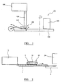
Figure 1 is a schematic representation of a prior art pressing system; -
Figure 2 is a schematic representation of apparatus in accordance with the invention; -
Figure 3 is a perspective view of apparatus in accordance with the invention; and -
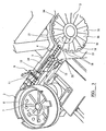
Figure 4 is an underside perspective view of an alternative embodiment of apparatus in accordance with the invention. - Referring to the drawings and initially to the prior art system of
figure 1 , there is shown pressing apparatus (101) including a rotary dial plate pressing table (102) having a vertical rotary axis about which the table rotates. The dial plate table (102) has a series of circumferentially spaced blank receiving stations which pass by a feed outlet (103) at which a respective blank is fed into a respective receiving station. The table is then rotated to carry the blanks to a pressing station (104) at which a press forming operation (coin stamping) is carried out. The table indexes rotationally with sufficient dwell time for loading of the blanks into the receiving stations from the feed outlet and performance of the pressing operation. The blanks are fed from an elevated hopper or bowl store (105) which is periodically loaded with blanks, and pass downwardly into a vertical guide tube (106) to form an upright column or stack of the blanks. Blanks are then fed from the bottom of the vertical stack by means of a reciprocating finger (107) which on its forward stroke forces the lowermost blank sideways from the stack at the feed outlet and into the adjacent dial plate table receiving station. - The prior art system described requires complex timing of the reciprocating finger (107) to pare off the lowermost blank from the stack at the precise moment the dial plate receiving station is in position. This results in frequent failure due to mechanical problems and mis-timing which results in down time to repair. Changeover to run the system for blanks of different sizes requires the stack guide tube, and dial plate receiving station arrangement to be reset. This results in the receiving station distribution about the circumference of the dial plate table changing and as a result the timing of the reciprocating finger of the feed system is required to be altered. This changeover procedure is time consuming and results in significant down time.
- Turning now to the system of the present invention as shown in
figures 2 and3 . The apparatus 1 comprises a rotary feed bowl (2), a feed system (3) including a guide feed channel (4) extending horizontally from the feed bowl (2) and a rotary dial plate table (5) (having a vertical rotary axis) positioned at the distal end of the guide feed channel (4). Blanks are periodically loaded into the feed bowl and dispensed from the feed bowl to pass along the guide feed channel in single file (in edge to edge relationship). The feed bowl has a rotary base (7) which rotates and agitates the blanks. A peripheral lip (8) ensures that only blanks which are orientated lying on a major face can pass under the influence of centrifugal force to a peripheral circumferential outlet (not shown). The feed bowl outlet is lined up with the proximal end of guide channel (4) The guide channel (4) can be varied in width to facilitate pressing runs of blanks of different sizes. A gauge arrangement (9) includes an aperture (10) in the base of the channel sized to ensure that blanks undersize by more than a given tolerance level are rejected by falling through the aperture (10). A deflection arm (11) also ensures that over-thickness blanks are deflected into a reject channel. The blanks are initially fed along the guide channel in single file by means of being pushed from the blank behind. In effect therefore the rotary drive of the feed bowl is the input driver to cause the blanks to move along the guide channel (4). However the guide channel (4) feed system includes a drive arrangement in the form of an endless belt drive (12). The belt (14) of the belt drive (12) contacts the upper surface of the single file blanks in the guide channel and urges them in the direction of the dial plate table (5). The end length of the guide channel (4) is horizontal and leads to a level entry/crossover point 20 at which the blanks are transferred to the dial plate table (5). The dial plate table (5) includes a circumferential edge (15), and an upper surface which has a series of sector elements (16) fixed to the table (5), each sector element including a circumference facing receiving recess (18) (receiving station) shaped and dimensioned to receive a single blank. When the dial plate table (5) is in a rotary position such that an empty receiving recess (18) of a respective slot is lined up at the cross over point (20) with the end of the guide channel (4), the endmost blank is urged by rearward force to move to enter and occupy the recess (18). The table then turns and the next in line blank is forced into abutment with the circumferential edge (15) of the dial plate table (5) awaiting the next vacant recess (18) to line up at the cross over point (20). The endless belt drive arrangement (12) performs the important function of ensuring that any spacing or gaps between blanks in the single file line in the guide channel (4) are closed. The apparatus operates at significant speed and it is important to ensure that the next in line blank at the crossover position (20) is always at the ready, in position at the end of channel (4), to be urged across to the dial plate table (5). - When in position on the table, the blanks are rotated to a pressing station (24) at which a press forming operation (for example coin stamping) is carried out. The table indexes rotationally with sufficient dwell time for loading of the blanks into the receiving stations (18) and performance of the pressing operation.
- In the embodiment shown in
figure 4 , the endless belt drive arrangement (12) is positioned beneath the guide channel (4), the upper length of the belt protruding, through a slot (31) in the base of the guide channel. The belt moves at a speed greater than the speed at which the blanks pass along the guide channel (4) ensuring that lagging blanks in the channel are brought up to engage with leading blanks in a convenient manner. It has been found that positioning the drive arrangement beneath the line of travelling blanks, such that the blanks are supported on the drive belt improves the reliability of this aspect of the design. The guide belt slips beneath the edge to edge contacting, in file blanks in the guide slot. Additionally, the drive arrangement contacting the underside of the blanks is preferred because it requires less re-organisation of apparatus parts when changing over the apparatus to deal with blanks of differing thickness. - In an alternative embodiment, the drive arrangement may comprise a non-contact drive arrangement such as a linear induction motor, preferably positioned in-line below the guide conduit. By using an induction motor, the number of moving parts for the apparatus is reduced aiding in ease of assembly, re-assembly and down time during maintenance or changeover. The use of a linear motor also enables simple external adjustment of the drive speed.
- The technique and system of the present invention does not require a complex timing arrangement to ensure transfer of blanks to the receiving station(18) at the dial plate table (5). Additionally, when the process run is converted to take blanks of a different size, there is no requirement to make timing adjustments or change feed tubes. The sector elements (16) are simply replaced with sector elements with appropriate sized receiving recesses and the width of the guide channel is adjusted. These features ensure that the operational down time is minimised.
Claims (9)
- Pressing apparatus for pressing blanks in a coining, stamping or press forming operation, the apparatus including a rotary pressing table to which the blanks are fed, a store receptacle for the blanks and a feed system for feeding the blanks dispensed from the store receptacle to the rotary pressing table, characterised in that the feed system including a guide conduit into which the blanks pass following dispensing from the store receptacle and along which the blanks are urged to file one behind another in edge to edge file relationship to an exit from the guide conduit, the blanks passing directly from the conduit into a receiving station of the rotary pressing table, and wherein the guide conduit extends transversely to the axis of rotation of the pressing table.
- Pressing apparatus according to claim 1, wherein:i) the blanks comprise disc form elements having opposed major faces and a minor dimension thickness edge; and/orii) the rotary pressing table has an upwardly extending axis of rotation; and/oriii) the guide conduit extends substantially horizontally.
- Pressing apparatus according to claim 1 or claim 2, wherein:i) the blanks pass along the conduit in single file; and/orii) the motion of the blank in passing into the receiving station of the rotary pressing table is in the same general direction as the motion of the blank along the conduit; and/oriii) the guide conduit is elongate, the blank moving in a direction in-line with the conduit in passing into the blank receiving station of the rotary pressing table.
- Pressing apparatus according to any preceding claim, wherein:i) the blanks are fed directly to the guide conduit from the receptacle store, in file one behind another; and/orii) the store receptacle includes a dispensing arrangement for dispensing the blanks in file in edge to edge relationship, to the guide conduit; and/oriii) the store receptacle includes rotary/centrifugal feed arrangement urging the blanks to be dispensed from the store receptacle; and/oriv) the feed system includes a biasing arrangement operational to bias blanks in the guide conduit in the direction of the rotary pressing table.
- Pressing apparatus according to any preceding claim, wherein:i) the biasing arrangement comprises a drive arrangement operational to drive blanks in the guide conduit in the direction of the rotary pressing table, preferably wherein the drive arrangement includes an actuator arranged to contact the surface of the blanks in the guide conduit; and/or the drive arrangement includes a non-contact device (such as a linear induction motor) operational to drive blanks in the guide conduit; and/or the biasing system includes an endless belt drive arranged to contact the blanks in file in the guide conduit.
- Pressing apparatus according to claim 5, wherein the actuator is located adjacent the underside surface of blanks in the guide channel.
- Pressing apparatus according to any preceding claim, wherein:i) the rotary pressing table rotates between successive positions in which blanks are urged to pass via the exit of the guide conduit into successive receiving stations of the rotary pressing table; and/orii) a plurality of receiving stations are provided on the rotary pressing table, each comprising a receiving recess provided in a sector element mounted to the surface of the table.
- Pressing apparatus according to any preceding claim, wherein:i) the receiving stations are replaceable on the rotary table to fit receiving stations for receipt of blanks of varying dimensions; and/orii) the rotary pressing table carries blanks to a pressing station where a press forming operation (such as coining or stamping) is carried out upon the blank.
- A press forming process in which blanks are fed from a receptacle store of blanks to a rotary pressing table, the blanks passing from the receptacle store into a guide conduit along which guide conduit the blanks are urged to file one behind another in edge to edge file relationship to an exit from the guide conduit, the blanks passing directly from the guide conduit into a receiving station of the rotary pressing table, wherein the guide extends transversely to the axis of rotation of the pressing table.
Priority Applications (1)
| Application Number | Priority Date | Filing Date | Title |
|---|---|---|---|
| PL06700949T PL1841602T3 (en) | 2005-01-26 | 2006-01-25 | Pressing system |
Applications Claiming Priority (2)
| Application Number | Priority Date | Filing Date | Title |
|---|---|---|---|
| GB0501594A GB2422567B (en) | 2005-01-26 | 2005-01-26 | Pressing system |
| PCT/GB2006/000233 WO2006095120A1 (en) | 2005-01-26 | 2006-01-25 | Pressing system |
Publications (3)
| Publication Number | Publication Date |
|---|---|
| EP1841602A1 EP1841602A1 (en) | 2007-10-10 |
| EP1841602B1 true EP1841602B1 (en) | 2012-01-11 |
| EP1841602B8 EP1841602B8 (en) | 2012-04-18 |
Family
ID=34259691
Family Applications (1)
| Application Number | Title | Priority Date | Filing Date |
|---|---|---|---|
| EP06700949A Expired - Lifetime EP1841602B8 (en) | 2005-01-26 | 2006-01-25 | Pressing system |
Country Status (9)
| Country | Link |
|---|---|
| US (1) | US20090064751A1 (en) |
| EP (1) | EP1841602B8 (en) |
| AT (1) | ATE540824T1 (en) |
| CA (1) | CA2595076A1 (en) |
| ES (1) | ES2380635T3 (en) |
| GB (1) | GB2422567B (en) |
| PL (1) | PL1841602T3 (en) |
| PT (1) | PT1841602E (en) |
| WO (1) | WO2006095120A1 (en) |
Cited By (1)
| Publication number | Priority date | Publication date | Assignee | Title |
|---|---|---|---|---|
| IT201700014643A1 (en) * | 2017-02-10 | 2018-08-10 | I M A Industria Macch Automatiche S P A In Sigla Ima S P A | Manufacturing group for filling containers and packaging line comprising this manufacturing group. |
Families Citing this family (4)
| Publication number | Priority date | Publication date | Assignee | Title |
|---|---|---|---|---|
| DE102016111434B3 (en) * | 2016-06-22 | 2017-12-14 | Schuler Pressen Gmbh | Plant for processing of disk parts |
| CN109623310B (en) * | 2018-11-22 | 2020-02-14 | 上海侨晨电器有限公司 | Guide rail type electronic component assembling equipment |
| CN109333029B (en) * | 2018-11-30 | 2023-11-24 | 宁波锦辉指针有限公司 | A fully automatic assembly machine for pointers |
| CA3163893C (en) | 2019-12-19 | 2024-05-21 | Monnaie Royale Canadienne/Royal Canadian Mint | Multi-component coin assembly system and method |
Family Cites Families (16)
| Publication number | Priority date | Publication date | Assignee | Title |
|---|---|---|---|---|
| DE823389C (en) * | 1950-05-23 | 1955-01-10 | Schuler L Ag | Feeding device for feeding small blanks |
| FR1043382A (en) * | 1951-09-29 | 1953-11-09 | Schuler L Ag | Device for feeding machines with small raw parts |
| DE1477384A1 (en) * | 1962-12-20 | 1969-02-13 | Hahn & Kolb | Device for removing the parting off pieces from turned parts |
| US3422472A (en) * | 1966-08-05 | 1969-01-21 | Illinois Tool Works | Method and apparatus for making drilling screw |
| GB1415496A (en) * | 1971-12-28 | 1975-11-26 | Taylor & Challen Ltd | Reciprocating feed mechanisms |
| US4213324A (en) * | 1978-07-21 | 1980-07-22 | Usm Corporation | Punch press and method for making can ends with closures |
| JPS5695774U (en) * | 1979-12-25 | 1981-07-29 | ||
| DE3339387A1 (en) * | 1982-11-30 | 1984-05-30 | Fa. Theodor Gräbener, 5902 Netphen | Device for feeding non-round plates into the tool of an embossing press |
| GB2131778B (en) * | 1982-11-30 | 1985-11-13 | Grabener Theodor | Feeding and orienting non-circular blanks |
| US4505370A (en) * | 1983-01-21 | 1985-03-19 | Reynolds Metals Company | Method for recycling cans |
| DE3510698A1 (en) * | 1985-03-23 | 1986-09-25 | L. Schuler GmbH, 7320 Göppingen | DEVICE FOR SEPARATING AND FEEDING PIECES AT A PRESS PRESS |
| DE3742745A1 (en) * | 1987-12-17 | 1989-07-06 | Schuler Gmbh L | MAINTENANCE MACHINE FOR RING CORE COINS |
| US5050722A (en) * | 1989-08-08 | 1991-09-24 | The West Company Incorporated | Apparatus for orienting articles |
| US5913428A (en) * | 1995-02-16 | 1999-06-22 | Graham; S. Neal | Vibratory bowl and associated parts orienting tooling with pivotal top confinement |
| GB2311952B (en) * | 1996-03-16 | 1998-08-12 | Rhodes Joseph Ltd | Improved blank feeding unit for a coining press |
| DE19843760A1 (en) * | 1998-09-24 | 2000-03-30 | Schuler Pressen Gmbh & Co | Stamping device for edge stamping of disks such as coins, including form wheel with rolling-out form segments and at least one dolly element of length sufficient to complete circle |
-
2005
- 2005-01-26 GB GB0501594A patent/GB2422567B/en not_active Expired - Fee Related
-
2006
- 2006-01-25 EP EP06700949A patent/EP1841602B8/en not_active Expired - Lifetime
- 2006-01-25 US US11/813,843 patent/US20090064751A1/en not_active Abandoned
- 2006-01-25 PL PL06700949T patent/PL1841602T3/en unknown
- 2006-01-25 PT PT06700949T patent/PT1841602E/en unknown
- 2006-01-25 AT AT06700949T patent/ATE540824T1/en active
- 2006-01-25 WO PCT/GB2006/000233 patent/WO2006095120A1/en not_active Ceased
- 2006-01-25 ES ES06700949T patent/ES2380635T3/en not_active Expired - Lifetime
- 2006-01-25 CA CA002595076A patent/CA2595076A1/en not_active Abandoned
Cited By (3)
| Publication number | Priority date | Publication date | Assignee | Title |
|---|---|---|---|---|
| IT201700014643A1 (en) * | 2017-02-10 | 2018-08-10 | I M A Industria Macch Automatiche S P A In Sigla Ima S P A | Manufacturing group for filling containers and packaging line comprising this manufacturing group. |
| WO2018146211A1 (en) * | 2017-02-10 | 2018-08-16 | I.M.A. Industria Macchine Automatiche S.P.A In Sigla Ima S.P.A. | Assembly for manufacturing fillable containers and a packaging line comprising such manufacturing assembly and a corresponing method |
| US11446856B2 (en) | 2017-02-10 | 2022-09-20 | I.M.A. Industria Macchine Automatiche S.P.A In Sigla Ima S.P.A. | Assembly for manufacturing fillable containers and a packaging line comprising such manufacturing assembly and a corresponding method |
Also Published As
| Publication number | Publication date |
|---|---|
| ES2380635T3 (en) | 2012-05-17 |
| WO2006095120A1 (en) | 2006-09-14 |
| EP1841602B8 (en) | 2012-04-18 |
| ES2380635T8 (en) | 2017-09-06 |
| PT1841602E (en) | 2012-04-13 |
| ATE540824T1 (en) | 2012-01-15 |
| EP1841602A1 (en) | 2007-10-10 |
| CA2595076A1 (en) | 2006-09-14 |
| PL1841602T3 (en) | 2012-08-31 |
| GB2422567A (en) | 2006-08-02 |
| US20090064751A1 (en) | 2009-03-12 |
| GB2422567B (en) | 2007-03-21 |
| GB0501594D0 (en) | 2005-03-02 |
Similar Documents
| Publication | Publication Date | Title |
|---|---|---|
| JP4551223B2 (en) | Container and generally elongated supply-distribution device | |
| US3690650A (en) | Method and apparatus for feeding sheet material into a hopper | |
| US4058866A (en) | Machines for handling and assembling fasteners and washers | |
| EP0257773A2 (en) | Device for counting and loading small items into containers | |
| US3282025A (en) | High speed capping machine | |
| AU2003232909A1 (en) | Chip sorting device | |
| US11565894B2 (en) | Rotary discharge of containers from a depalletizer | |
| US20090064751A1 (en) | Pressing System | |
| US3054167A (en) | Capping machine | |
| US20180075684A1 (en) | Chip sorting devices and related assemblies, components and methods | |
| US4732263A (en) | Bulk feeder for electronic components | |
| EP1642737A3 (en) | Returner incorpotated in automatic feeder and recording apparatus or liquid ejecting apparatus provided with the same | |
| US5494399A (en) | Can end distributor apparatus | |
| GB2493059A (en) | Method and apparatus for forming bi-metallic coin blanks | |
| KR101216534B1 (en) | A supply equipment for tablet inspection apparatus | |
| US2711550A (en) | Method of and machine for permanently assembling nut and washer elements | |
| CN113788301A (en) | Fixed number takes out bolt machine | |
| CN108113887B (en) | a discharge structure | |
| US1908898A (en) | Apparatus for assembling linings in receptacle closure caps | |
| US7427003B1 (en) | Disk feeder and unstacker | |
| EP0085646A1 (en) | Apparatus for counting and collecting paperboards | |
| JP2019085185A (en) | Roller feeding device and roller feeding method | |
| CN216511098U (en) | Fixed-number bolt taking-out machine | |
| US2714214A (en) | Nut and washer assembly selector | |
| CN110921267A (en) | Rotary feeding device |
Legal Events
| Date | Code | Title | Description |
|---|---|---|---|
| PUAI | Public reference made under article 153(3) epc to a published international application that has entered the european phase |
Free format text: ORIGINAL CODE: 0009012 |
|
| 17P | Request for examination filed |
Effective date: 20070710 |
|
| AK | Designated contracting states |
Kind code of ref document: A1 Designated state(s): AT BE BG CH CY CZ DE DK EE ES FI FR GB GR HU IE IS IT LI LT LU LV MC NL PL PT RO SE SI SK TR |
|
| DAX | Request for extension of the european patent (deleted) | ||
| 17Q | First examination report despatched |
Effective date: 20090428 |
|
| GRAP | Despatch of communication of intention to grant a patent |
Free format text: ORIGINAL CODE: EPIDOSNIGR1 |
|
| GRAS | Grant fee paid |
Free format text: ORIGINAL CODE: EPIDOSNIGR3 |
|
| GRAA | (expected) grant |
Free format text: ORIGINAL CODE: 0009210 |
|
| RBV | Designated contracting states (corrected) |
Designated state(s): AT BE BG CH CY CZ DE DK EE ES FI FR GR HU IE IS IT LI LT LU LV MC NL PL PT RO SE SI SK TR |
|
| AK | Designated contracting states |
Kind code of ref document: B1 Designated state(s): AT BE BG CH CY CZ DE DK EE ES FI FR GR HU IE IS IT LI LT LU LV MC NL PL PT RO SE SI SK TR |
|
| REG | Reference to a national code |
Ref country code: CH Ref legal event code: EP |
|
| REG | Reference to a national code |
Ref country code: AT Ref legal event code: REF Ref document number: 540824 Country of ref document: AT Kind code of ref document: T Effective date: 20120115 |
|
| REG | Reference to a national code |
Ref country code: DE Ref legal event code: R081 Ref document number: 602006026974 Country of ref document: DE Owner name: SCHULER PRESSEN GMBH, DE Free format text: FORMER OWNER: THE SOLICITOR FOR THE AFFAIRS OF HER MAJESTY'S TREASURY, LLANTRISANT, GB |
|
| REG | Reference to a national code |
Ref country code: IE Ref legal event code: FG4D |
|
| RAP2 | Party data changed (patent owner data changed or rights of a patent transferred) |
Owner name: THE ROYAL MINT LIMITED |
|
| REG | Reference to a national code |
Ref country code: DE Ref legal event code: R096 Ref document number: 602006026974 Country of ref document: DE Effective date: 20120315 |
|
| REG | Reference to a national code |
Ref country code: NL Ref legal event code: T3 |
|
| REG | Reference to a national code |
Ref country code: PT Ref legal event code: SC4A Free format text: AVAILABILITY OF NATIONAL TRANSLATION Effective date: 20120403 |
|
| REG | Reference to a national code |
Ref country code: ES Ref legal event code: FG2A Ref document number: 2380635 Country of ref document: ES Kind code of ref document: T3 Effective date: 20120517 |
|
| PG25 | Lapsed in a contracting state [announced via postgrant information from national office to epo] |
Ref country code: SI Free format text: LAPSE BECAUSE OF FAILURE TO SUBMIT A TRANSLATION OF THE DESCRIPTION OR TO PAY THE FEE WITHIN THE PRESCRIBED TIME-LIMIT Effective date: 20120111 |
|
| REG | Reference to a national code |
Ref country code: SK Ref legal event code: T3 Ref document number: E 11489 Country of ref document: SK |
|
| REG | Reference to a national code |
Ref country code: DE Ref legal event code: R082 Ref document number: 602006026974 Country of ref document: DE Representative=s name: RUEGER | ABEL PATENT- UND RECHTSANWAELTE, DE Ref country code: DE Ref legal event code: R082 Ref document number: 602006026974 Country of ref document: DE Representative=s name: HASELTINE LAKE LLP, DE Ref country code: DE Ref legal event code: R082 Ref document number: 602006026974 Country of ref document: DE Representative=s name: RUEGER, BARTHELT & ABEL, DE Ref country code: DE Ref legal event code: R081 Ref document number: 602006026974 Country of ref document: DE Owner name: SCHULER PRESSEN GMBH, DE Free format text: FORMER OWNER: THE SOLICITOR FOR THE AFFAIRS OF HER MAJESTY'S TREASURY, LLANTRISANT, GB Ref country code: DE Ref legal event code: R082 Ref document number: 602006026974 Country of ref document: DE Representative=s name: RUEGER ABEL PATENT- UND RECHTSANWAELTE, DE |
|
| PG25 | Lapsed in a contracting state [announced via postgrant information from national office to epo] |
Ref country code: IS Free format text: LAPSE BECAUSE OF FAILURE TO SUBMIT A TRANSLATION OF THE DESCRIPTION OR TO PAY THE FEE WITHIN THE PRESCRIBED TIME-LIMIT Effective date: 20120511 Ref country code: BG Free format text: LAPSE BECAUSE OF FAILURE TO SUBMIT A TRANSLATION OF THE DESCRIPTION OR TO PAY THE FEE WITHIN THE PRESCRIBED TIME-LIMIT Effective date: 20120411 |
|
| PG25 | Lapsed in a contracting state [announced via postgrant information from national office to epo] |
Ref country code: MC Free format text: LAPSE BECAUSE OF NON-PAYMENT OF DUE FEES Effective date: 20120131 Ref country code: LV Free format text: LAPSE BECAUSE OF FAILURE TO SUBMIT A TRANSLATION OF THE DESCRIPTION OR TO PAY THE FEE WITHIN THE PRESCRIBED TIME-LIMIT Effective date: 20120111 Ref country code: GR Free format text: LAPSE BECAUSE OF FAILURE TO SUBMIT A TRANSLATION OF THE DESCRIPTION OR TO PAY THE FEE WITHIN THE PRESCRIBED TIME-LIMIT Effective date: 20120412 |
|
| REG | Reference to a national code |
Ref country code: PL Ref legal event code: T3 Ref country code: CH Ref legal event code: PL |
|
| PG25 | Lapsed in a contracting state [announced via postgrant information from national office to epo] |
Ref country code: CY Free format text: LAPSE BECAUSE OF FAILURE TO SUBMIT A TRANSLATION OF THE DESCRIPTION OR TO PAY THE FEE WITHIN THE PRESCRIBED TIME-LIMIT Effective date: 20120111 |
|
| PG25 | Lapsed in a contracting state [announced via postgrant information from national office to epo] |
Ref country code: LI Free format text: LAPSE BECAUSE OF NON-PAYMENT OF DUE FEES Effective date: 20120131 Ref country code: CH Free format text: LAPSE BECAUSE OF NON-PAYMENT OF DUE FEES Effective date: 20120131 Ref country code: EE Free format text: LAPSE BECAUSE OF FAILURE TO SUBMIT A TRANSLATION OF THE DESCRIPTION OR TO PAY THE FEE WITHIN THE PRESCRIBED TIME-LIMIT Effective date: 20120111 Ref country code: SE Free format text: LAPSE BECAUSE OF FAILURE TO SUBMIT A TRANSLATION OF THE DESCRIPTION OR TO PAY THE FEE WITHIN THE PRESCRIBED TIME-LIMIT Effective date: 20120111 Ref country code: DK Free format text: LAPSE BECAUSE OF FAILURE TO SUBMIT A TRANSLATION OF THE DESCRIPTION OR TO PAY THE FEE WITHIN THE PRESCRIBED TIME-LIMIT Effective date: 20120111 Ref country code: CZ Free format text: LAPSE BECAUSE OF FAILURE TO SUBMIT A TRANSLATION OF THE DESCRIPTION OR TO PAY THE FEE WITHIN THE PRESCRIBED TIME-LIMIT Effective date: 20120111 |
|
| PLBE | No opposition filed within time limit |
Free format text: ORIGINAL CODE: 0009261 |
|
| STAA | Information on the status of an ep patent application or granted ep patent |
Free format text: STATUS: NO OPPOSITION FILED WITHIN TIME LIMIT |
|
| 26N | No opposition filed |
Effective date: 20121012 |
|
| REG | Reference to a national code |
Ref country code: DE Ref legal event code: R097 Ref document number: 602006026974 Country of ref document: DE Effective date: 20121012 |
|
| PG25 | Lapsed in a contracting state [announced via postgrant information from national office to epo] |
Ref country code: LU Free format text: LAPSE BECAUSE OF NON-PAYMENT OF DUE FEES Effective date: 20120125 |
|
| PG25 | Lapsed in a contracting state [announced via postgrant information from national office to epo] |
Ref country code: HU Free format text: LAPSE BECAUSE OF FAILURE TO SUBMIT A TRANSLATION OF THE DESCRIPTION OR TO PAY THE FEE WITHIN THE PRESCRIBED TIME-LIMIT Effective date: 20060125 |
|
| REG | Reference to a national code |
Ref country code: FR Ref legal event code: PLFP Year of fee payment: 11 |
|
| PGFP | Annual fee paid to national office [announced via postgrant information from national office to epo] |
Ref country code: IE Payment date: 20160125 Year of fee payment: 11 Ref country code: LT Payment date: 20160104 Year of fee payment: 11 Ref country code: SK Payment date: 20160114 Year of fee payment: 11 Ref country code: TR Payment date: 20160125 Year of fee payment: 11 |
|
| PGFP | Annual fee paid to national office [announced via postgrant information from national office to epo] |
Ref country code: PT Payment date: 20151230 Year of fee payment: 11 Ref country code: RO Payment date: 20160111 Year of fee payment: 11 |
|
| REG | Reference to a national code |
Ref country code: FR Ref legal event code: PLFP Year of fee payment: 12 |
|
| REG | Reference to a national code |
Ref country code: DE Ref legal event code: R082 Ref document number: 602006026974 Country of ref document: DE Representative=s name: RUEGER | ABEL PATENT- UND RECHTSANWAELTE, DE Ref country code: DE Ref legal event code: R082 Ref document number: 602006026974 Country of ref document: DE Representative=s name: RUEGER ABEL PATENTANWAELTE PARTGMBB, DE Ref country code: DE Ref legal event code: R082 Ref document number: 602006026974 Country of ref document: DE Representative=s name: RUEGER, BARTHELT & ABEL, DE Ref country code: DE Ref legal event code: R082 Ref document number: 602006026974 Country of ref document: DE Representative=s name: RUEGER ABEL PATENT- UND RECHTSANWAELTE, DE |
|
| REG | Reference to a national code |
Ref country code: LT Ref legal event code: MM4D Effective date: 20170125 |
|
| REG | Reference to a national code |
Ref country code: DE Ref legal event code: R082 Ref document number: 602006026974 Country of ref document: DE Representative=s name: RUEGER | ABEL PATENT- UND RECHTSANWAELTE, DE Ref country code: DE Ref legal event code: R082 Ref document number: 602006026974 Country of ref document: DE Representative=s name: RUEGER ABEL PATENTANWAELTE PARTGMBB, DE Ref country code: DE Ref legal event code: R082 Ref document number: 602006026974 Country of ref document: DE Representative=s name: RUEGER, BARTHELT & ABEL, DE Ref country code: DE Ref legal event code: R081 Ref document number: 602006026974 Country of ref document: DE Owner name: SCHULER PRESSEN GMBH, DE Free format text: FORMER OWNER: THE ROYAL MINT LTD., PONTYCLUN, MID GLAMORGAN, GB Ref country code: DE Ref legal event code: R082 Ref document number: 602006026974 Country of ref document: DE Representative=s name: RUEGER ABEL PATENT- UND RECHTSANWAELTE, DE |
|
| REG | Reference to a national code |
Ref country code: SK Ref legal event code: MM4A Ref document number: E 11489 Country of ref document: SK Effective date: 20170125 |
|
| PG25 | Lapsed in a contracting state [announced via postgrant information from national office to epo] |
Ref country code: SK Free format text: LAPSE BECAUSE OF NON-PAYMENT OF DUE FEES Effective date: 20170125 Ref country code: RO Free format text: LAPSE BECAUSE OF NON-PAYMENT OF DUE FEES Effective date: 20170125 Ref country code: LT Free format text: LAPSE BECAUSE OF NON-PAYMENT OF DUE FEES Effective date: 20170125 |
|
| REG | Reference to a national code |
Ref country code: IE Ref legal event code: MM4A |
|
| PG25 | Lapsed in a contracting state [announced via postgrant information from national office to epo] |
Ref country code: PT Free format text: LAPSE BECAUSE OF NON-PAYMENT OF DUE FEES Effective date: 20170725 |
|
| REG | Reference to a national code |
Ref country code: BE Ref legal event code: PD Owner name: SCHULER PRESSEN GMBH; DE Free format text: DETAILS ASSIGNMENT: CHANGE OF OWNER(S), AFFECTATION / CESSION; FORMER OWNER NAME: THE ROYAL MINT LIMITED Effective date: 20170825 |
|
| REG | Reference to a national code |
Ref country code: FR Ref legal event code: PLFP Year of fee payment: 13 |
|
| REG | Reference to a national code |
Ref country code: ES Ref legal event code: PC2A Owner name: SCHULER PRESSEN GMBH Effective date: 20180213 |
|
| REG | Reference to a national code |
Ref country code: FR Ref legal event code: TP Owner name: SCHULER PRESSEN GMBH, DE Effective date: 20180123 |
|
| PG25 | Lapsed in a contracting state [announced via postgrant information from national office to epo] |
Ref country code: IE Free format text: LAPSE BECAUSE OF NON-PAYMENT OF DUE FEES Effective date: 20170125 |
|
| REG | Reference to a national code |
Ref country code: AT Ref legal event code: PC Ref document number: 540824 Country of ref document: AT Kind code of ref document: T Owner name: SCHULER PRESSEN GMBH, DE Effective date: 20180322 |
|
| PG25 | Lapsed in a contracting state [announced via postgrant information from national office to epo] |
Ref country code: TR Free format text: LAPSE BECAUSE OF NON-PAYMENT OF DUE FEES Effective date: 20170125 |
|
| P01 | Opt-out of the competence of the unified patent court (upc) registered |
Effective date: 20230803 |
|
| PGFP | Annual fee paid to national office [announced via postgrant information from national office to epo] |
Ref country code: NL Payment date: 20250122 Year of fee payment: 20 |
|
| PGFP | Annual fee paid to national office [announced via postgrant information from national office to epo] |
Ref country code: DE Payment date: 20241206 Year of fee payment: 20 |
|
| PGFP | Annual fee paid to national office [announced via postgrant information from national office to epo] |
Ref country code: FI Payment date: 20250121 Year of fee payment: 20 |
|
| PGFP | Annual fee paid to national office [announced via postgrant information from national office to epo] |
Ref country code: ES Payment date: 20250214 Year of fee payment: 20 |
|
| PGFP | Annual fee paid to national office [announced via postgrant information from national office to epo] |
Ref country code: AT Payment date: 20250120 Year of fee payment: 20 Ref country code: BE Payment date: 20250121 Year of fee payment: 20 |
|
| PGFP | Annual fee paid to national office [announced via postgrant information from national office to epo] |
Ref country code: PL Payment date: 20250113 Year of fee payment: 20 Ref country code: FR Payment date: 20250123 Year of fee payment: 20 |
|
| PGFP | Annual fee paid to national office [announced via postgrant information from national office to epo] |
Ref country code: IT Payment date: 20250131 Year of fee payment: 20 |
|
| PG2D | Information on lapse in contracting state deleted |
Ref country code: BE |
|
| REG | Reference to a national code |
Ref country code: DE Ref legal event code: R071 Ref document number: 602006026974 Country of ref document: DE |
|
| REG | Reference to a national code |
Ref country code: NL Ref legal event code: MK Effective date: 20260124 |
|
| REG | Reference to a national code |
Ref country code: ES Ref legal event code: FD2A Effective date: 20260130 |
|
| REG | Reference to a national code |
Ref country code: BE Ref legal event code: MK Effective date: 20260125 |
|
| REG | Reference to a national code |
Ref country code: AT Ref legal event code: MK07 Ref document number: 540824 Country of ref document: AT Kind code of ref document: T Effective date: 20260125 |
|
| PG25 | Lapsed in a contracting state [announced via postgrant information from national office to epo] |
Ref country code: ES Free format text: LAPSE BECAUSE OF EXPIRATION OF PROTECTION Effective date: 20260126 |