EP1841552B1 - Method for removing blind fasteners - Google Patents
Method for removing blind fasteners Download PDFInfo
- Publication number
- EP1841552B1 EP1841552B1 EP06718655.1A EP06718655A EP1841552B1 EP 1841552 B1 EP1841552 B1 EP 1841552B1 EP 06718655 A EP06718655 A EP 06718655A EP 1841552 B1 EP1841552 B1 EP 1841552B1
- Authority
- EP
- European Patent Office
- Prior art keywords
- core bolt
- head portion
- bore
- tool
- workpiece
- Prior art date
- Legal status (The legal status is an assumption and is not a legal conclusion. Google has not performed a legal analysis and makes no representation as to the accuracy of the status listed.)
- Active
Links
- 238000000034 method Methods 0.000 title claims description 26
- 230000000295 complement effect Effects 0.000 claims 1
- 238000009434 installation Methods 0.000 description 8
- 230000000712 assembly Effects 0.000 description 3
- 238000000429 assembly Methods 0.000 description 3
- 125000006850 spacer group Chemical group 0.000 description 2
- 230000001419 dependent effect Effects 0.000 description 1
- 239000000284 extract Substances 0.000 description 1
- 238000012986 modification Methods 0.000 description 1
- 230000004048 modification Effects 0.000 description 1
Images


Classifications
-
- B—PERFORMING OPERATIONS; TRANSPORTING
- B21—MECHANICAL METAL-WORKING WITHOUT ESSENTIALLY REMOVING MATERIAL; PUNCHING METAL
- B21J—FORGING; HAMMERING; PRESSING METAL; RIVETING; FORGE FURNACES
- B21J15/00—Riveting
- B21J15/38—Accessories for use in connection with riveting, e.g. pliers for upsetting; Hand tools for riveting
- B21J15/50—Removing or cutting devices for rivets
-
- Y—GENERAL TAGGING OF NEW TECHNOLOGICAL DEVELOPMENTS; GENERAL TAGGING OF CROSS-SECTIONAL TECHNOLOGIES SPANNING OVER SEVERAL SECTIONS OF THE IPC; TECHNICAL SUBJECTS COVERED BY FORMER USPC CROSS-REFERENCE ART COLLECTIONS [XRACs] AND DIGESTS
- Y10—TECHNICAL SUBJECTS COVERED BY FORMER USPC
- Y10T—TECHNICAL SUBJECTS COVERED BY FORMER US CLASSIFICATION
- Y10T29/00—Metal working
- Y10T29/49—Method of mechanical manufacture
- Y10T29/49815—Disassembling
- Y10T29/49821—Disassembling by altering or destroying work part or connector
Definitions
- the following disclosure relates generally to blind fasteners and, more particularly, to a method for removing blind fasteners.
- blind fastener is often used to describe a fastener that can be fully installed from a single side of a structural assembly. Pop rivets and one-sided installation (OSI) bolts are two known types of blind fasteners.
- Figures 1A and 1B are partial cross-sectional views illustrating two stages in a method of installing a prior art blind fastener 100
- Figure 1C is an end view of the blind fastener 100.
- the blind fastener 100 includes a core bolt 110 extending through a passage 109 in a body 112.
- the core bolt 110 includes an exposed stem 118 and an externally threaded portion 115.
- the externally threaded portion 115 engages a nut 116.
- the nut 116 bears against a sleeve 114.
- the stem 118 of the core bolt 110 includes flats 111a and 111b, and the body 112 includes a head portion 119 having a plurality of recesses 113 (identified individually as recesses 113a-d).
- the blind fastener 100 to install the blind fastener 100, it is first inserted through a bore 104 in a first part 101 and a second part 102. A minimum distance D1 is required between the second part 102 and a third part 103 to provide clearance for the blind fastener 100 during installation.
- prongs on a nose adapter of an installation tool (not shown) are engaged with the recesses 113 in the head portion 119 to prevent rotation of the body 112.
- a wrench adapter on the installation tool then engages the flats 111 on the core bolt stem 118 and rotates the core bolt 110 about its longitudinal axis. Rotation of the core bolt 110 in this manner causes the nut 116 to move toward the body 112.
- Figures 2A-2F are partial cross-sectional views illustrating a method for removing the blind fastener 100 from the first part 101 and the second part 102 in accordance with the prior art.
- the method involves use of a drill tool 200 having a drill bit 204 rotatably disposed in an adapter 206.
- a plurality of prongs 202 (identified individually as a first prong 202a and a second prong 202b) extending outwardly from the adapter 206 engage the corresponding recesses 113 in the head portion 119 of the fastener body 112.
- the prongs 202 prevent the body 112 from rotating while the drill bit 204 removes a head portion 221 of the core bolt 110, as shown in Figure 2B .
- a punch 230 Is used to drive the remaining portion of the core bolt 110 out the backside of the fastener body 112.
- an increased backside clearance D2 is required between the second part 102 and the third part 103 to ensure that the core bolt 110 will fall clear of the body 112.
- a pilot tip 242 of an end mill 240 is inserted into the body 112, and a cutter portion 244 of the end mill 240 removes the head portion 119 of the body 112.
- a piloted rivet set 232 or other suitable tool is then inserted through the bore 104 and used to drive the body 112 out the backside of the bore 104.
- the minimum backside clearance D1 is all that is required to adequately install the blind fastener 100.
- removal of the blind fastener 100 by the method described above requires increasing the backside clearance to D2.
- Increasing the backside clearance from D1 to D2 solely for the purpose of fastener removal results in a larger structural assembly than would otherwise be required.
- the disadvantages of a larger structural assembly include an increase in structural weight and a decrease in usable space.
- the present invention is directed generally toward a method for removing blind fasteners from aircraft structures and other assemblies.
- a method in accordance with the invention is used to remove a blind fastener from a bore, as defined in independent claim 1.
- Preferred embodiments are defined in the dependent claims.
- Figures 3A and 3B are partial cross-sectional views illustrating an installation of the blind fastener 100 in a structural assembly 300 configured in accordance with an embodiment of the invention.
- the structural assembly 300 includes a first part 301 (e.g., a first aircraft part) positioned against a second part 302 (e.g., a second aircraft part).
- the blind fastener 100 can be installed in the first part 301 and the second part 301 using the method described above with reference to Figures 1A-1C .
- the second part 302 is spaced apart from a third part 303 by the minimum backside clearance D1 discussed above with reference to Figure 1A .
- the minimum backside clearance D1 is considerably less than the increased backside clearance D2 used in the prior art structural assembly described above with reference to Figures 1A-1C .
- the minimum backside clearance D1 is only slightly greater than a length P of the portion of the blind fastener 100 protruding from the second part 302. Even though the minimum backside clearance D1 of the present invention is considerably less than the increased backside clearance D2 of the prior art, the blind fastener 100 can still be easily removed from the structural assembly 300 by using the method described below with reference to Figures 4A-4D .
- Figures 4A-4D are partial cross-sectional views illustrating a method for removing the blind fastener 100 from the first part 301 and the second part 302 in accordance with an embodiment of the invention.
- the head portion 221 of the core bolt 110 is removed using the drill tool 200 as described above with reference to Figures 2A and 2B .
- other suitable tools and/or methods can be used to remove the head portion 221 from the core bolt 110.
- Such methods can include, for example, the use of an end mill, grinder, chisel, or other tool.
- the punch 230 or other suitable tool is inserted into the body 112 and brought to bear against the remaining portion of the core bolt 110.
- the punch 230 is then used to drive the core bolt 110 outwardly toward the third part 303.
- the removal tool 440 includes a screw extractor or similar device (e.g., a "Back-Out”) having a tapered portion 442 with a plurality of reverse-direction threads configured to engage the interior walls of the passage 109.
- the tapered portion 442 is inserted into the passage 109 in a first direction 451, and then rotated in a counterclockwise direction 453 to engage the body 112.
- the removal tool 440 can then be pulled in a second direction 452 to extract the body 112 from the bore 304.
- the core bolt 110 will be left laying in what is essentially an oversized hole. As a result, the core bolt 110 can be easily tapped out of the bore 304 at an angle sufficient to clear the third part 303.
- one feature of the illustrated embodiment is that the minimum distance between the second part 302 and the third part 303 can be reduced to D1, which is only slightly greater than the length P of the portion of the blind fastener 100 protruding beyond the second part 302.
- D1 the minimum distance between the second part 302 and the third part 303
- One advantage of this feature is that it allows the structural assembly 300 to be made smaller and lighter than the prior art structural assembly described above with reference to Figures 1A-2F .
- the fastener removal method described herein provides the additional advantage of allowing blind fasteners, such as the blind fastener 100, to be retrofit in those structural assemblies that heretofore did not provide sufficient backside clearance for fastener removal.
- the blind fastener 100 and other fasteners of similar configuration can now be used in a number of applications that were previously considered unfeasible.
- Figures 5A-5C are various side cross-sectional views of a fastener body removal tool 550 (“removal tool 550") configured in accordance with an embodiment of the invention.
- the removal tool 550 includes an engagement portion 501 operably coupled to a pulling portion 503.
- the engagement portion 501 is configured to engage an interior portion of the fastener body 112.
- the pulling portion 503 is configured to extract the fastener body 112 from the bore 304 after the engagement portion 501 has been engaged with the fastener body 112.
- the engagement portion 501 includes an expanding sleeve 564 carried by a distal end portion of a core pin 554.
- the core pin 554 extends through a spacer 562 and a threaded bushing 560, and is pivotally coupled to a cam 558 by means of a barrel nut 556.
- a user-operable handle 552 extends outwardly from the cam 558. Rotation of the handle 552 in direction R causes the cam 558 to rotate against the bushing 560, thereby drawing the core pin 554 through the bushing 560 in direction D. As described in greater detail below, this movement of the core pin 554 causes the expanding sleeve 564 to expand outwardly and engage the fastener body 112. As shown in Figure 5C , when the handle 552 has been fully rotated in direction R, a tab 571 extending outwardly from the handle 552 is received by a notch 572 in the threaded bushing 560,.
- the pulling portion 503 includes the bushing 560 which is threaded into a support 568.
- the support 568 is configured to contact the first part 301 and position the engagement portion 501 relative to the fastener body 112.
- the handle 552 can be rotated counterclockwise to unthread the bushing 560 from the support 568.
- the engagement portion 501 extracts the fastener body 112 from the bore 304.
- Figures 6A and 6B are enlarged cross-sectional views illustrating operation of the engagement portion 501 of the removal tool 550 described above with reference to Figures 5A-C .
- the expanding sleeve 564 is captured between a first tapered surface 681 of the core pin 554 and a second tapered surface 682 of a sleeve expander 666.
- the sleeve expander 666 is a ring-shaped member that bears against the spacer 562.
- the tip of the core pin 554 moves toward the sleeve expander 666, the first tapered surface 681 cooperates with the second tapered surface 682 to force the expanding sleeve 564 outward in direction C, as shown In Figure 6B .
- the expanding sleeve 564 When the expanding sleeve 564 is positioned within a fastener body (e.g., the fastener body 112 of Figures 5A-C ), this expansion causes the expanding sleeve 564 to press against the fastener body and firmly grip it for subsequent removal.
- the expanding sleeve 564 includes a longitudinal cut at one location that enables it to expand and contract.
- the expanding sleeve 564 can also include various serrations, knurling, and/or other surface features on an outer surface 684 to enhance the ability of the expanding ring to grip fastener bodies for removal.
Description
- The following disclosure relates generally to blind fasteners and, more particularly, to a method for removing blind fasteners.
- The term "blind fastener" is often used to describe a fastener that can be fully installed from a single side of a structural assembly. Pop rivets and one-sided installation (OSI) bolts are two known types of blind fasteners.
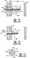
Figures 1A and 1B are partial cross-sectional views illustrating two stages in a method of installing a prior artblind fastener 100, andFigure 1C is an end view of theblind fastener 100. Referring first toFigure 1A , theblind fastener 100 includes acore bolt 110 extending through apassage 109 in abody 112. Thecore bolt 110 includes an exposedstem 118 and an externally threadedportion 115. The externally threadedportion 115 engages anut 116. Thenut 116 bears against asleeve 114. As shown inFigure 1C , thestem 118 of thecore bolt 110 includesflats body 112 includes ahead portion 119 having a plurality of recesses 113 (identified individually asrecesses 113a-d). - Returning to
Figure 1A , to install theblind fastener 100, it is first inserted through abore 104 in afirst part 101 and asecond part 102. A minimum distance D1 is required between thesecond part 102 and athird part 103 to provide clearance for theblind fastener 100 during installation. Next, prongs on a nose adapter of an installation tool (not shown) are engaged with the recesses 113 in thehead portion 119 to prevent rotation of thebody 112. A wrench adapter on the installation tool then engages the flats 111 on thecore bolt stem 118 and rotates thecore bolt 110 about its longitudinal axis. Rotation of thecore bolt 110 in this manner causes thenut 116 to move toward thebody 112. As this happens, thesleeve 114 flares out over thebody 112 and presses against thesecond part 102 as shown inFigure 1B . As thesleeve 114 is compressed, thecore bolt stem 118 becomes harder and harder to turn until ultimately thestem 118 breaks off at a preset torque level. The foregoing installation procedure and related fastener details are described in the product specification entitled "OSI-BOLT™ -- HIGH STRENGTH FASTENER FOR PRIMARY STRUCTURE" provided by Monogram Aerospace Fasteners, Inc. of 3423 South Garfield Avenue, Los Angeles, California 90022, and inU.S. Patent Nos. 5,498,110 and5,634,751 . -
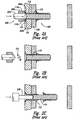
Figures 2A-2F are partial cross-sectional views illustrating a method for removing theblind fastener 100 from thefirst part 101 and thesecond part 102 in accordance with the prior art. Referring first toFigure 2A , the method involves use of adrill tool 200 having adrill bit 204 rotatably disposed in anadapter 206. A plurality of prongs 202 (identified individually as afirst prong 202a and asecond prong 202b) extending outwardly from theadapter 206 engage the corresponding recesses 113 in thehead portion 119 of thefastener body 112. The prongs 202 prevent thebody 112 from rotating while thedrill bit 204 removes ahead portion 221 of thecore bolt 110, as shown inFigure 2B . - Referring next to
Figure 2C , after thehead portion 221 of thecore bolt 110 has been removed, apunch 230 Is used to drive the remaining portion of thecore bolt 110 out the backside of thefastener body 112. As shown inFigure 2D , an increased backside clearance D2 is required between thesecond part 102 and thethird part 103 to ensure that thecore bolt 110 will fall clear of thebody 112. - Referring next to
Figure 2E , apilot tip 242 of anend mill 240 is inserted into thebody 112, and acutter portion 244 of theend mill 240 removes thehead portion 119 of thebody 112. As shown inFigure 2F , a pilotedrivet set 232 or other suitable tool is then inserted through thebore 104 and used to drive thebody 112 out the backside of thebore 104. - As
Figure 1A illustrates, the minimum backside clearance D1 is all that is required to adequately install theblind fastener 100. As shown inFigure 2D , however, removal of theblind fastener 100 by the method described above requires increasing the backside clearance to D2. Increasing the backside clearance from D1 to D2 solely for the purpose of fastener removal results in a larger structural assembly than would otherwise be required. In aircraft and other structures, the disadvantages of a larger structural assembly include an increase in structural weight and a decrease in usable space. - The present invention is directed generally toward a method for removing blind fasteners from aircraft structures and other assemblies. A method in accordance with the invention is used to remove a blind fastener from a bore, as defined in independent claim 1. Preferred embodiments are defined in the dependent claims.
-
-
Figures 1A-1B are partial cross-sectional views illustrating a method for installing a blind fastener in accordance with the prior art, andFigure 1C is an end view of the blind fastener. -
Figures 2A-2F are partial cross-sectional views illustrating a method for removing the blind fastener ofFigures 1A-1C in accordance with the prior art. -
Figures 3A-3B are partial cross-sectional views illustrating an installation of the blind fastener ofFigures 1A-1C in a structural assembly configured in accordance with an embodiment of the invention. -
Figures 4A-4D are partial cross-sectional views illustrating a method for removing the blind fastener ofFigures 1A-1C in accordance with an embodiment of the invention. -
Figures 5A-5C are various side cross-sectional views of a blind fastener removal tool configured in accordance with another embodiment of the invention. -
Figures 6A and 6B are enlarged cross-sectional views of the fastener engagement portion of the blind fastener removal tool ofFigures 5A-5C . - The following disclosure describes various methods and apparatuses for removing blind fasteners from structural assemblies. Certain details are set forth in the following description to provide a thorough understanding of various embodiments of the invention. Other details describing well-known structures and systems often associated with one-sided installation bolts and other blind fasteners are not set forth, however, to avoid unnecessarily obscuring the description of the various embodiments of the invention.
- Many of the details, dimensions, angles and other features shown in the Figures are merely illustrative of particular embodiments of the invention. Accordingly, other embodiments can have other details, dimensions, angles and features without departing from the scope of the present invention.
- In the Figures, identical reference numbers identify identical or at least generally similar elements. To facilitate the discussion of any particular element, the most significant digit or digits of any reference number refer to the Figure in which that element is first introduced. For example,
element 303 is first introduced and discussed with reference toFigure 3 . -
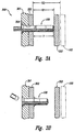
Figures 3A and 3B are partial cross-sectional views illustrating an installation of theblind fastener 100 in astructural assembly 300 configured in accordance with an embodiment of the invention. Referring to these Figures together, thestructural assembly 300 includes a first part 301 (e.g., a first aircraft part) positioned against a second part 302 (e.g., a second aircraft part). Theblind fastener 100 can be installed in thefirst part 301 and thesecond part 301 using the method described above with reference toFigures 1A-1C . - In one aspect of this embodiment, the
second part 302 is spaced apart from athird part 303 by the minimum backside clearance D1 discussed above with reference toFigure 1A . As the reader will observe, the minimum backside clearance D1 is considerably less than the increased backside clearance D2 used in the prior art structural assembly described above with reference toFigures 1A-1C . In fact, the minimum backside clearance D1 is only slightly greater than a length P of the portion of theblind fastener 100 protruding from thesecond part 302. Even though the minimum backside clearance D1 of the present invention is considerably less than the increased backside clearance D2 of the prior art, theblind fastener 100 can still be easily removed from thestructural assembly 300 by using the method described below with reference toFigures 4A-4D . -
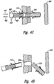
Figures 4A-4D are partial cross-sectional views illustrating a method for removing theblind fastener 100 from thefirst part 301 and thesecond part 302 in accordance with an embodiment of the invention. Referring first toFigure 4A , thehead portion 221 of thecore bolt 110 is removed using thedrill tool 200 as described above with reference toFigures 2A and 2B . In other embodiments, other suitable tools and/or methods can be used to remove thehead portion 221 from thecore bolt 110. Such methods can include, for example, the use of an end mill, grinder, chisel, or other tool. - Referring next to
Figure 4B , after thehead portion 221 of thecore bolt 110 has been removed, thepunch 230 or other suitable tool is inserted into thebody 112 and brought to bear against the remaining portion of thecore bolt 110. Thepunch 230 is then used to drive thecore bolt 110 outwardly toward thethird part 303. The close proximity of thethird part 303 to thesecond part 302, however, prevents thecore bolt 110 from being driven completely out of thefastener body 112. - As shown in
Figure 4C , once thecore bolt 110 has been driven partially through thebody 112, a fastener body removal tool 440 ("removal tool 440") is inserted into thebody 112. In the illustrated embodiment, theremoval tool 440 includes a screw extractor or similar device (e.g., a "Back-Out") having a taperedportion 442 with a plurality of reverse-direction threads configured to engage the interior walls of thepassage 109. The taperedportion 442 is inserted into thepassage 109 in afirst direction 451, and then rotated in acounterclockwise direction 453 to engage thebody 112. Theremoval tool 440 can then be pulled in asecond direction 452 to extract thebody 112 from thebore 304. - Referring next to
Figure 4D , once thebody 112 has been extracted from thebore 304, thecore bolt 110 will be left laying in what is essentially an oversized hole. As a result, thecore bolt 110 can be easily tapped out of thebore 304 at an angle sufficient to clear thethird part 303. - As mentioned above with reference to
Figure 3A , one feature of the illustrated embodiment is that the minimum distance between thesecond part 302 and thethird part 303 can be reduced to D1, which is only slightly greater than the length P of the portion of theblind fastener 100 protruding beyond thesecond part 302. One advantage of this feature is that it allows thestructural assembly 300 to be made smaller and lighter than the prior art structural assembly described above with reference toFigures 1A-2F . Further, the fastener removal method described herein provides the additional advantage of allowing blind fasteners, such as theblind fastener 100, to be retrofit in those structural assemblies that heretofore did not provide sufficient backside clearance for fastener removal. As a result, theblind fastener 100 and other fasteners of similar configuration can now be used in a number of applications that were previously considered unfeasible. -
Figures 5A-5C are various side cross-sectional views of a fastener body removal tool 550 ("removal tool 550") configured in accordance with an embodiment of the invention. Referring first toFigures 5A and 5B , theremoval tool 550 includes anengagement portion 501 operably coupled to a pullingportion 503. Theengagement portion 501 is configured to engage an interior portion of thefastener body 112. The pullingportion 503 is configured to extract thefastener body 112 from thebore 304 after theengagement portion 501 has been engaged with thefastener body 112. - In the illustrated embodiment, the
engagement portion 501 includes an expandingsleeve 564 carried by a distal end portion of acore pin 554. Thecore pin 554 extends through aspacer 562 and a threadedbushing 560, and is pivotally coupled to acam 558 by means of abarrel nut 556. A user-operable handle 552 extends outwardly from thecam 558. Rotation of thehandle 552 in direction R causes thecam 558 to rotate against thebushing 560, thereby drawing thecore pin 554 through thebushing 560 in direction D. As described in greater detail below, this movement of thecore pin 554 causes the expandingsleeve 564 to expand outwardly and engage thefastener body 112. As shown inFigure 5C , when thehandle 552 has been fully rotated in direction R, atab 571 extending outwardly from thehandle 552 is received by anotch 572 in the threadedbushing 560,. - In the illustrated embodiment, the pulling
portion 503 includes thebushing 560 which is threaded into asupport 568. Thesupport 568 is configured to contact thefirst part 301 and position theengagement portion 501 relative to thefastener body 112. Once thetab 571 on thehandle 552 has been received by thenotch 572 in thebushing 560, thehandle 552 can be rotated counterclockwise to unthread thebushing 560 from thesupport 568. As shown inFigure 5C , as thebushing 560 moves away from thesupport 568 in direction D, theengagement portion 501 extracts thefastener body 112 from thebore 304. -
Figures 6A and 6B are enlarged cross-sectional views illustrating operation of theengagement portion 501 of theremoval tool 550 described above with reference toFigures 5A-C . Referring first toFigure 6A , the expandingsleeve 564 is captured between a firsttapered surface 681 of thecore pin 554 and a secondtapered surface 682 of asleeve expander 666. Thesleeve expander 666 is a ring-shaped member that bears against thespacer 562. As the tip of thecore pin 554 moves toward thesleeve expander 666, the firsttapered surface 681 cooperates with the secondtapered surface 682 to force the expandingsleeve 564 outward in direction C, as shown InFigure 6B . When the expandingsleeve 564 is positioned within a fastener body (e.g., thefastener body 112 ofFigures 5A-C ), this expansion causes the expandingsleeve 564 to press against the fastener body and firmly grip it for subsequent removal. Although not illustrated inFigures 6A-B , the expandingsleeve 564 includes a longitudinal cut at one location that enables it to expand and contract. In addition, the expandingsleeve 564 can also include various serrations, knurling, and/or other surface features on anouter surface 684 to enhance the ability of the expanding ring to grip fastener bodies for removal. - From the foregoing, it will be appreciated that specific embodiments of the invention have been described herein for purposes of illustration, but that various modifications may be made without deviating from the scope of the invention as defined by the appended claims.
Claims (6)
- A method for removing a blind fastener (100) from a bore through a workpiece having an accessible side and an inaccessible side, the workpiece spaced apart from another part by at least a first distance, the blind fastener (100) having a core bolt (110), a body (112), a flared sleeve (114), and a nut (116), the body (112) having an enlarged head having a frustoconical longitudinal cross section, the core bolt (110) having a head portion (221) that has a maximum diameter greater than a maximum diameter of a remaining portion of the core bolt (110) and arranged on the accessible side of the workpiece, the remaining portion of the core bolt (110) extending through a cylindrical passage in the body (112), the interior surface of the body being complementary to the exterior surface of a portion of the core bolt, the body (110) located in the bore, the nut engaged with the core bolt (110) and bearing against the flared sleeve, the flared sleeve flaring out over a portion of the body (112) and being pressed against the inaccessible side of the workpiece, the first distance comprising a distance the body (112) protrudes from the workpiece on the inaccessible side of the workpiece, the length of the flared sleeve prior to flaring, and the length of the nut, the method comprising:removing the head portion (221) from the core bolt (110);driving the remaining portion of the core bolt (110) at least partially through the passage in the body (112) in a first direction towards the inaccessible side of the workpiece such that the flared sleeve is no longer over the body (112); and characterised in that the remaining portion of the core bolt (110) remains temporarily supported by the body (112) while the body (112) is being extracted from the bore in a second direction, opposite the first direction, the method further comprisingextracting the body (112) from the bore in the second direction.
- The method of claim 1 wherein extracting the body (112) from the bore includes inserting a tool (440) into the passage and pulling the body (112) in the second direction with the tool (440).
- The method of claim 1 wherein the head portion (221) of the core bolt (110) is a first head portion, and wherein extracting the body (112) from the bore includes inserting a tool (440) through the enlarged head portion of the body (112) and pulling the body (112) in the second direction with the tool (440).
- The method of claim 1 wherein extracting the body (112) from the bore includes engaging a threaded portion of a tool (440) with an interior portion of the body (112) and pulling the body (112) in the second direction with the tool (440).
- The method of claim 1 wherein extracting the body (112) from the bore includes engaging an interior portion of the body (112) with a screw extractor and pulling the body (112) in the second direction with the screw extractor.
- The method of claim 1 wherein the head portion (221) of the core bolt (110) is a first head portion, and wherein removing the first head portion from the core bolt (110) includes engaging the enlarged head portion of the body (112) to prevent the body (112) from rotating about a longitudinal axis.
Applications Claiming Priority (2)
| Application Number | Priority Date | Filing Date | Title |
|---|---|---|---|
| US11/042,753 US7555820B2 (en) | 2005-01-24 | 2005-01-24 | Methods for removing blind fasteners |
| PCT/US2006/001607 WO2006081099A1 (en) | 2005-01-24 | 2006-01-17 | Methods and apparatuses for removing blind fasteners |
Publications (2)
| Publication Number | Publication Date |
|---|---|
| EP1841552A1 EP1841552A1 (en) | 2007-10-10 |
| EP1841552B1 true EP1841552B1 (en) | 2018-03-07 |
Family
ID=36218785
Family Applications (1)
| Application Number | Title | Priority Date | Filing Date |
|---|---|---|---|
| EP06718655.1A Active EP1841552B1 (en) | 2005-01-24 | 2006-01-17 | Method for removing blind fasteners |
Country Status (6)
| Country | Link |
|---|---|
| US (1) | US7555820B2 (en) |
| EP (1) | EP1841552B1 (en) |
| JP (1) | JP5171265B2 (en) |
| CA (1) | CA2595450C (en) |
| ES (1) | ES2672168T3 (en) |
| WO (1) | WO2006081099A1 (en) |
Families Citing this family (13)
| Publication number | Priority date | Publication date | Assignee | Title |
|---|---|---|---|---|
| DK174983B1 (en) * | 2002-04-10 | 2004-04-05 | Hollister Inc | Empty ostomy bag with integrated closure |
| US8387226B2 (en) * | 2008-12-08 | 2013-03-05 | The Boeing Company | Method and apparatus for removing blind fasteners |
| FR2980724B1 (en) * | 2011-10-04 | 2014-10-17 | Airbus Operations Sas | METHOD FOR DESTRUCTION OF A BLIND FIXATION AND DEVICE FOR IMPLEMENTING SAID METHOD |
| US10072696B2 (en) * | 2012-03-07 | 2018-09-11 | Kabushiki Kaisha Kinki | Detaching method of filling member and filling member used therein and cutter blade using this filling member |
| US9284971B2 (en) * | 2012-04-04 | 2016-03-15 | John D. Pratt | Fastener and method of installing same |
| GB2522042B (en) * | 2014-01-10 | 2018-01-10 | Thales Holdings Uk Plc | Handling tool with internal clamping means for a fixture hole |
| JP2019010694A (en) * | 2017-06-29 | 2019-01-24 | 豊田鉄工株式会社 | Blind nut dismount tool and blind nut dismount structure |
| WO2019089360A1 (en) * | 2017-10-31 | 2019-05-09 | Allfast Fastening Systems | Chip break bolt head |
| US10639703B2 (en) | 2018-05-18 | 2020-05-05 | United Technologies Corporation | Rivet extractor |
| FR3088559B1 (en) | 2018-11-20 | 2021-01-29 | Lisi Aerospace | Device for removing a fastener installed in a hole |
| DE102019112731A1 (en) | 2019-05-15 | 2020-11-19 | Airbus Operations Gmbh | Method for dismantling a blind rivet in a workpiece arrangement |
| CN111676429B (en) * | 2020-06-24 | 2022-03-01 | 南京钢铁股份有限公司 | Hot-rolled weather-resistant angle steel with good low-temperature toughness and production method thereof |
| US20230083921A1 (en) * | 2021-09-10 | 2023-03-16 | The Boeing Company | Blind fasteners and associated methods for installing blind fasteners |
Citations (2)
| Publication number | Priority date | Publication date | Assignee | Title |
|---|---|---|---|---|
| US5498110A (en) * | 1994-02-25 | 1996-03-12 | Monogram Aerospace Fasteners | Blind fastener with deformable sleeve |
| US20020124380A1 (en) * | 2001-03-08 | 2002-09-12 | Zardus Paul M. | Loose blind rivet assembly apparatus and method |
Family Cites Families (7)
| Publication number | Priority date | Publication date | Assignee | Title |
|---|---|---|---|---|
| US1873250A (en) | 1929-01-05 | 1932-08-23 | Bell Telephone Labor Inc | Bushing extractor |
| US2814089A (en) | 1954-07-12 | 1957-11-26 | Patton Mfg Company | Apparatus for and method of producing curved electrotypes |
| US3071848A (en) | 1961-03-22 | 1963-01-08 | Charles C Gaither Inc | Extractor tool |
| GB2288648A (en) * | 1994-04-12 | 1995-10-25 | Avdel Systems Ltd | Removable rivet |
| DE10012845A1 (en) * | 2000-03-16 | 2001-09-20 | Emhart Inc | Method and device for removing punch rivets from a workpiece |
| US6568062B1 (en) * | 1997-06-19 | 2003-05-27 | Newfrey Llc | Methods of removing self-piercing rivets set into a workpiece and devices for implementing the methods |
| JP2000225435A (en) * | 1999-02-04 | 2000-08-15 | Ricoh Co Ltd | Method and device for overhauling tightening member |
-
2005
- 2005-01-24 US US11/042,753 patent/US7555820B2/en active Active
-
2006
- 2006-01-17 WO PCT/US2006/001607 patent/WO2006081099A1/en active Application Filing
- 2006-01-17 EP EP06718655.1A patent/EP1841552B1/en active Active
- 2006-01-17 CA CA2595450A patent/CA2595450C/en active Active
- 2006-01-17 ES ES06718655.1T patent/ES2672168T3/en active Active
- 2006-01-17 JP JP2007552214A patent/JP5171265B2/en active Active
Patent Citations (3)
| Publication number | Priority date | Publication date | Assignee | Title |
|---|---|---|---|---|
| US5498110A (en) * | 1994-02-25 | 1996-03-12 | Monogram Aerospace Fasteners | Blind fastener with deformable sleeve |
| US5634751A (en) * | 1994-02-25 | 1997-06-03 | Monogram Aerospace Fasteners | Blind fastener with deformable sleeve |
| US20020124380A1 (en) * | 2001-03-08 | 2002-09-12 | Zardus Paul M. | Loose blind rivet assembly apparatus and method |
Also Published As
| Publication number | Publication date |
|---|---|
| EP1841552A1 (en) | 2007-10-10 |
| JP2008528290A (en) | 2008-07-31 |
| JP5171265B2 (en) | 2013-03-27 |
| WO2006081099A1 (en) | 2006-08-03 |
| CA2595450C (en) | 2010-04-13 |
| ES2672168T3 (en) | 2018-06-12 |
| US7555820B2 (en) | 2009-07-07 |
| CA2595450A1 (en) | 2006-08-03 |
| US20060165507A1 (en) | 2006-07-27 |
Similar Documents
| Publication | Publication Date | Title |
|---|---|---|
| EP1841552B1 (en) | Method for removing blind fasteners | |
| US8517649B2 (en) | Dual-action disposable clamp | |
| US8511952B2 (en) | Dual-action disposable clamp | |
| EP3717145B1 (en) | Automatic double-action fastener installation tool | |
| EP1635994B1 (en) | Blind fastener and nose assembly for installation of the blind fastener | |
| US8398345B2 (en) | Low profile dual-action disposable clamp | |
| CA2516052C (en) | Blind fastener and method of removing it from a workpiece | |
| EP1691087A2 (en) | Frangible Blind Rivet | |
| US20060075617A1 (en) | Performance enhancing repair tool | |
| CA2057183A1 (en) | Fastener with internal threaded installation means | |
| EP1327082B1 (en) | Blind fastener | |
| EP1666740A2 (en) | Blind rivet | |
| ZA200507051B (en) | Blind fastener and method of removing it from a workpiece |
Legal Events
| Date | Code | Title | Description |
|---|---|---|---|
| PUAI | Public reference made under article 153(3) epc to a published international application that has entered the european phase |
Free format text: ORIGINAL CODE: 0009012 |
|
| 17P | Request for examination filed |
Effective date: 20070726 |
|
| AK | Designated contracting states |
Kind code of ref document: A1 Designated state(s): AT BE BG CH CY CZ DE DK EE ES FI FR GB GR HU IE IS IT LI LT LU LV MC NL PL PT RO SE SI SK TR |
|
| 17Q | First examination report despatched |
Effective date: 20080115 |
|
| DAX | Request for extension of the european patent (deleted) | ||
| GRAP | Despatch of communication of intention to grant a patent |
Free format text: ORIGINAL CODE: EPIDOSNIGR1 |
|
| STAA | Information on the status of an ep patent application or granted ep patent |
Free format text: STATUS: GRANT OF PATENT IS INTENDED |
|
| INTG | Intention to grant announced |
Effective date: 20170928 |
|
| GRAS | Grant fee paid |
Free format text: ORIGINAL CODE: EPIDOSNIGR3 |
|
| GRAA | (expected) grant |
Free format text: ORIGINAL CODE: 0009210 |
|
| STAA | Information on the status of an ep patent application or granted ep patent |
Free format text: STATUS: THE PATENT HAS BEEN GRANTED |
|
| AK | Designated contracting states |
Kind code of ref document: B1 Designated state(s): AT BE BG CH CY CZ DE DK EE ES FI FR GB GR HU IE IS IT LI LT LU LV MC NL PL PT RO SE SI SK TR |
|
| REG | Reference to a national code |
Ref country code: GB Ref legal event code: FG4D |
|
| REG | Reference to a national code |
Ref country code: CH Ref legal event code: EP Ref country code: AT Ref legal event code: REF Ref document number: 976006 Country of ref document: AT Kind code of ref document: T Effective date: 20180315 |
|
| REG | Reference to a national code |
Ref country code: IE Ref legal event code: FG4D |
|
| REG | Reference to a national code |
Ref country code: DE Ref legal event code: R096 Ref document number: 602006054860 Country of ref document: DE |
|
| REG | Reference to a national code |
Ref country code: ES Ref legal event code: FG2A Ref document number: 2672168 Country of ref document: ES Kind code of ref document: T3 Effective date: 20180612 |
|
| REG | Reference to a national code |
Ref country code: NL Ref legal event code: MP Effective date: 20180307 |
|
| REG | Reference to a national code |
Ref country code: LT Ref legal event code: MG4D |
|
| PG25 | Lapsed in a contracting state [announced via postgrant information from national office to epo] |
Ref country code: CY Free format text: LAPSE BECAUSE OF FAILURE TO SUBMIT A TRANSLATION OF THE DESCRIPTION OR TO PAY THE FEE WITHIN THE PRESCRIBED TIME-LIMIT Effective date: 20180307 Ref country code: LT Free format text: LAPSE BECAUSE OF FAILURE TO SUBMIT A TRANSLATION OF THE DESCRIPTION OR TO PAY THE FEE WITHIN THE PRESCRIBED TIME-LIMIT Effective date: 20180307 Ref country code: FI Free format text: LAPSE BECAUSE OF FAILURE TO SUBMIT A TRANSLATION OF THE DESCRIPTION OR TO PAY THE FEE WITHIN THE PRESCRIBED TIME-LIMIT Effective date: 20180307 |
|
| REG | Reference to a national code |
Ref country code: AT Ref legal event code: MK05 Ref document number: 976006 Country of ref document: AT Kind code of ref document: T Effective date: 20180307 |
|
| PG25 | Lapsed in a contracting state [announced via postgrant information from national office to epo] |
Ref country code: BG Free format text: LAPSE BECAUSE OF FAILURE TO SUBMIT A TRANSLATION OF THE DESCRIPTION OR TO PAY THE FEE WITHIN THE PRESCRIBED TIME-LIMIT Effective date: 20180607 Ref country code: SE Free format text: LAPSE BECAUSE OF FAILURE TO SUBMIT A TRANSLATION OF THE DESCRIPTION OR TO PAY THE FEE WITHIN THE PRESCRIBED TIME-LIMIT Effective date: 20180307 Ref country code: LV Free format text: LAPSE BECAUSE OF FAILURE TO SUBMIT A TRANSLATION OF THE DESCRIPTION OR TO PAY THE FEE WITHIN THE PRESCRIBED TIME-LIMIT Effective date: 20180307 Ref country code: GR Free format text: LAPSE BECAUSE OF FAILURE TO SUBMIT A TRANSLATION OF THE DESCRIPTION OR TO PAY THE FEE WITHIN THE PRESCRIBED TIME-LIMIT Effective date: 20180608 |
|
| PG25 | Lapsed in a contracting state [announced via postgrant information from national office to epo] |
Ref country code: PL Free format text: LAPSE BECAUSE OF FAILURE TO SUBMIT A TRANSLATION OF THE DESCRIPTION OR TO PAY THE FEE WITHIN THE PRESCRIBED TIME-LIMIT Effective date: 20180307 Ref country code: EE Free format text: LAPSE BECAUSE OF FAILURE TO SUBMIT A TRANSLATION OF THE DESCRIPTION OR TO PAY THE FEE WITHIN THE PRESCRIBED TIME-LIMIT Effective date: 20180307 Ref country code: NL Free format text: LAPSE BECAUSE OF FAILURE TO SUBMIT A TRANSLATION OF THE DESCRIPTION OR TO PAY THE FEE WITHIN THE PRESCRIBED TIME-LIMIT Effective date: 20180307 Ref country code: RO Free format text: LAPSE BECAUSE OF FAILURE TO SUBMIT A TRANSLATION OF THE DESCRIPTION OR TO PAY THE FEE WITHIN THE PRESCRIBED TIME-LIMIT Effective date: 20180307 |
|
| PG25 | Lapsed in a contracting state [announced via postgrant information from national office to epo] |
Ref country code: AT Free format text: LAPSE BECAUSE OF FAILURE TO SUBMIT A TRANSLATION OF THE DESCRIPTION OR TO PAY THE FEE WITHIN THE PRESCRIBED TIME-LIMIT Effective date: 20180307 Ref country code: SK Free format text: LAPSE BECAUSE OF FAILURE TO SUBMIT A TRANSLATION OF THE DESCRIPTION OR TO PAY THE FEE WITHIN THE PRESCRIBED TIME-LIMIT Effective date: 20180307 Ref country code: CZ Free format text: LAPSE BECAUSE OF FAILURE TO SUBMIT A TRANSLATION OF THE DESCRIPTION OR TO PAY THE FEE WITHIN THE PRESCRIBED TIME-LIMIT Effective date: 20180307 |
|
| REG | Reference to a national code |
Ref country code: DE Ref legal event code: R097 Ref document number: 602006054860 Country of ref document: DE |
|
| PG25 | Lapsed in a contracting state [announced via postgrant information from national office to epo] |
Ref country code: PT Free format text: LAPSE BECAUSE OF FAILURE TO SUBMIT A TRANSLATION OF THE DESCRIPTION OR TO PAY THE FEE WITHIN THE PRESCRIBED TIME-LIMIT Effective date: 20180709 |
|
| PLBE | No opposition filed within time limit |
Free format text: ORIGINAL CODE: 0009261 |
|
| STAA | Information on the status of an ep patent application or granted ep patent |
Free format text: STATUS: NO OPPOSITION FILED WITHIN TIME LIMIT |
|
| PG25 | Lapsed in a contracting state [announced via postgrant information from national office to epo] |
Ref country code: DK Free format text: LAPSE BECAUSE OF FAILURE TO SUBMIT A TRANSLATION OF THE DESCRIPTION OR TO PAY THE FEE WITHIN THE PRESCRIBED TIME-LIMIT Effective date: 20180307 |
|
| 26N | No opposition filed |
Effective date: 20181210 |
|
| PG25 | Lapsed in a contracting state [announced via postgrant information from national office to epo] |
Ref country code: SI Free format text: LAPSE BECAUSE OF FAILURE TO SUBMIT A TRANSLATION OF THE DESCRIPTION OR TO PAY THE FEE WITHIN THE PRESCRIBED TIME-LIMIT Effective date: 20180307 |
|
| PG25 | Lapsed in a contracting state [announced via postgrant information from national office to epo] |
Ref country code: MC Free format text: LAPSE BECAUSE OF FAILURE TO SUBMIT A TRANSLATION OF THE DESCRIPTION OR TO PAY THE FEE WITHIN THE PRESCRIBED TIME-LIMIT Effective date: 20180307 |
|
| REG | Reference to a national code |
Ref country code: CH Ref legal event code: PL |
|
| PG25 | Lapsed in a contracting state [announced via postgrant information from national office to epo] |
Ref country code: LU Free format text: LAPSE BECAUSE OF NON-PAYMENT OF DUE FEES Effective date: 20190117 |
|
| REG | Reference to a national code |
Ref country code: BE Ref legal event code: MM Effective date: 20190131 |
|
| REG | Reference to a national code |
Ref country code: IE Ref legal event code: MM4A |
|
| PG25 | Lapsed in a contracting state [announced via postgrant information from national office to epo] |
Ref country code: BE Free format text: LAPSE BECAUSE OF NON-PAYMENT OF DUE FEES Effective date: 20190131 |
|
| PG25 | Lapsed in a contracting state [announced via postgrant information from national office to epo] |
Ref country code: CH Free format text: LAPSE BECAUSE OF NON-PAYMENT OF DUE FEES Effective date: 20190131 Ref country code: LI Free format text: LAPSE BECAUSE OF NON-PAYMENT OF DUE FEES Effective date: 20190131 |
|
| REG | Reference to a national code |
Ref country code: DE Ref legal event code: R082 Ref document number: 602006054860 Country of ref document: DE Representative=s name: MAIER, LL.M., MICHAEL C., DE Ref country code: DE Ref legal event code: R082 Ref document number: 602006054860 Country of ref document: DE Representative=s name: BOULT WADE TENNANT LLP, DE |
|
| PG25 | Lapsed in a contracting state [announced via postgrant information from national office to epo] |
Ref country code: IE Free format text: LAPSE BECAUSE OF NON-PAYMENT OF DUE FEES Effective date: 20190117 |
|
| REG | Reference to a national code |
Ref country code: DE Ref legal event code: R082 Ref document number: 602006054860 Country of ref document: DE Representative=s name: BOULT WADE TENNANT LLP, DE |
|
| PG25 | Lapsed in a contracting state [announced via postgrant information from national office to epo] |
Ref country code: TR Free format text: LAPSE BECAUSE OF FAILURE TO SUBMIT A TRANSLATION OF THE DESCRIPTION OR TO PAY THE FEE WITHIN THE PRESCRIBED TIME-LIMIT Effective date: 20180307 |
|
| PG25 | Lapsed in a contracting state [announced via postgrant information from national office to epo] |
Ref country code: IS Free format text: LAPSE BECAUSE OF FAILURE TO SUBMIT A TRANSLATION OF THE DESCRIPTION OR TO PAY THE FEE WITHIN THE PRESCRIBED TIME-LIMIT Effective date: 20180707 |
|
| PG25 | Lapsed in a contracting state [announced via postgrant information from national office to epo] |
Ref country code: HU Free format text: LAPSE BECAUSE OF FAILURE TO SUBMIT A TRANSLATION OF THE DESCRIPTION OR TO PAY THE FEE WITHIN THE PRESCRIBED TIME-LIMIT; INVALID AB INITIO Effective date: 20060117 |
|
| PGFP | Annual fee paid to national office [announced via postgrant information from national office to epo] |
Ref country code: FR Payment date: 20230125 Year of fee payment: 18 Ref country code: ES Payment date: 20230201 Year of fee payment: 18 |
|
| PGFP | Annual fee paid to national office [announced via postgrant information from national office to epo] |
Ref country code: IT Payment date: 20230120 Year of fee payment: 18 Ref country code: GB Payment date: 20230127 Year of fee payment: 18 Ref country code: DE Payment date: 20230127 Year of fee payment: 18 |
|
| P01 | Opt-out of the competence of the unified patent court (upc) registered |
Effective date: 20230503 |
|
| PGFP | Annual fee paid to national office [announced via postgrant information from national office to epo] |
Ref country code: ES Payment date: 20240201 Year of fee payment: 19 |