EP1841049A1 - Electromagnetic micro-generator - Google Patents
Electromagnetic micro-generator Download PDFInfo
- Publication number
- EP1841049A1 EP1841049A1 EP06111810A EP06111810A EP1841049A1 EP 1841049 A1 EP1841049 A1 EP 1841049A1 EP 06111810 A EP06111810 A EP 06111810A EP 06111810 A EP06111810 A EP 06111810A EP 1841049 A1 EP1841049 A1 EP 1841049A1
- Authority
- EP
- European Patent Office
- Prior art keywords
- micro
- wafer
- coils
- generator
- mems
- Prior art date
- Legal status (The legal status is an assumption and is not a legal conclusion. Google has not performed a legal analysis and makes no representation as to the accuracy of the status listed.)
- Granted
Links
- 229910052751 metal Inorganic materials 0.000 claims abstract description 14
- 239000002184 metal Substances 0.000 claims abstract description 14
- 239000000696 magnetic material Substances 0.000 claims description 8
- 238000004519 manufacturing process Methods 0.000 claims description 7
- 238000000034 method Methods 0.000 claims description 4
- 238000000708 deep reactive-ion etching Methods 0.000 claims description 3
- 238000005530 etching Methods 0.000 claims description 2
- 238000007747 plating Methods 0.000 claims description 2
- 230000008021 deposition Effects 0.000 claims 1
- 238000002955 isolation Methods 0.000 claims 1
- BGPVFRJUHWVFKM-UHFFFAOYSA-N N1=C2C=CC=CC2=[N+]([O-])C1(CC1)CCC21N=C1C=CC=CC1=[N+]2[O-] Chemical compound N1=C2C=CC=CC2=[N+]([O-])C1(CC1)CCC21N=C1C=CC=CC1=[N+]2[O-] BGPVFRJUHWVFKM-UHFFFAOYSA-N 0.000 description 6
- 238000005516 engineering process Methods 0.000 description 6
- 238000004891 communication Methods 0.000 description 2
- 238000005476 soldering Methods 0.000 description 2
- RYGMFSIKBFXOCR-UHFFFAOYSA-N Copper Chemical compound [Cu] RYGMFSIKBFXOCR-UHFFFAOYSA-N 0.000 description 1
- 239000004411 aluminium Substances 0.000 description 1
- 229910052782 aluminium Inorganic materials 0.000 description 1
- XAGFODPZIPBFFR-UHFFFAOYSA-N aluminium Chemical compound [Al] XAGFODPZIPBFFR-UHFFFAOYSA-N 0.000 description 1
- 239000013590 bulk material Substances 0.000 description 1
- 230000000295 complement effect Effects 0.000 description 1
- 229910052802 copper Inorganic materials 0.000 description 1
- 239000010949 copper Substances 0.000 description 1
- 230000001419 dependent effect Effects 0.000 description 1
- 238000000151 deposition Methods 0.000 description 1
- 238000009713 electroplating Methods 0.000 description 1
- 239000000284 extract Substances 0.000 description 1
- 229910044991 metal oxide Inorganic materials 0.000 description 1
- 150000004706 metal oxides Chemical class 0.000 description 1
- 230000003071 parasitic effect Effects 0.000 description 1
- 238000010248 power generation Methods 0.000 description 1
- 239000004065 semiconductor Substances 0.000 description 1
- 230000035945 sensitivity Effects 0.000 description 1
- 238000004544 sputter deposition Methods 0.000 description 1
- 239000010409 thin film Substances 0.000 description 1
- 230000009466 transformation Effects 0.000 description 1
Images

Classifications
-
- H—ELECTRICITY
- H02—GENERATION; CONVERSION OR DISTRIBUTION OF ELECTRIC POWER
- H02K—DYNAMO-ELECTRIC MACHINES
- H02K35/00—Generators with reciprocating, oscillating or vibrating coil system, magnet, armature or other part of the magnetic circuit
- H02K35/02—Generators with reciprocating, oscillating or vibrating coil system, magnet, armature or other part of the magnetic circuit with moving magnets and stationary coil systems
Definitions
- the present invention relates to a micro-generator for generating useful electrical power from the external environment and a corresponding method of manufacturing a micro generator.
- Micromechanical systems need alternatives to batteries for providing power which meets the miniaturisation requirements of such systems.
- power supply solutions that are on a small enough scale to be adequately integrated with micro systems.
- traditional piezoelectric bulk material may be glued or soldered on to other mechanical members and electrically joined by soldering or a combination of soldering and wire bonding.
- the present invention aims to address this problem and to provide a low cost fully integrated micro-generator which is compatible with integrated circuit technology.
- a micro-generator comprising: an integrated circuit (IC) wafer; a microelectromechanical system (MEMS) wafer bonded to the IC wafer, the MEMS wafer comprising a micromechanical element arranged to move in use; a plurality of first metal coils, the coils being realized as part of the IC wafer and/or the MEMS wafer; a plurality of trenches formed in the IC wafer and/or the MEMS wafer and associated with the first coils; a plurality of micro-magnets, a micro-magnet being associated with each trench, wherein the micro-magnets are formed from a magnet layer deposited or plated or bonded to the MEMS wafer and/or the IC wafer; wherein upon movement of the micromechanical element in use, the micro-magnets are arranged to move within the trenches relative to the first coils such that a voltage is induced in the first coils.
- IC integrated circuit
- MEMS microelectromechanical system
- a micro-generator comprising the steps of:
- a micro-transformer for a micro-generator comprising:
- an example micro-generator comprises an integrated circuit (IC) chip 1 with a plurality of metal micro-coils 2 within the chip 1.
- the coils 2 are realised as part of the IC chip 1 and are serially coupled.
- the micro-generator also comprises a microelectromechanical system (MEMS) chip 3 which includes an energy pick-up such as a mass-spring system 3a or a diaphragm (not shown).
- MEMS microelectromechanical system
- a plurality of micro-magnets 4 are formed on the MEMS chip 3 and a plurality of trenches 5 are formed in the IC chip 1 to accommodate the magnets 4.
- the coils 2 and magnets 4 are positioned within the IC chip 1 in such a way that the magnets 4 can move within the trenches 5 close to the coils 2 to induce a current in the coils 2.
- the magnets 4 surround the trenches 5.
- the MEMS chip 3 and IC chip 1 are bonded together at the bond regions 6 shown in figure 1. Bond pads 7 are formed on the IC chip 1.
- FIGs 2A to 2C show alternative coil 2, magnet 4 and trench 5 arrangements to that shown in figure 1.
- a magnet 4 is isolated by means of an empty trench 5 either side of the trench 5 occupied by the magnet 4. This helps reduce parasitics and other losses.
- losses are reduced by means of metal shields 8 in between coils 2.
- losses are reduced by means of further trenches 9 formed in the MEMS chip 3 adjacent to coils 2.
- an example micro-transformer according to the present invention has the same form as the micro-generator described above.
- An example magnet 4 is shown which is accommodated in a trench 5 such that the magnet 4 can move within the trench 5.
- a set of primary coils 10 surround the magnet 4 and a set of secondary coils 11 surround the primary coils 10, the secondary coils 11 having more turns than the primary coils.
- Figure 3B shows an alternative arrangement of the example of figure 3A. In this arrangement there is still provided a set of primary coils 10 and a set of secondary coils 11, although the two are positioned above one another and interlaced.
- the primary coil 10 will have fewer turns (layers) than the secondary coil 11, although the actual number and relative proportions of primary and secondary coils will be dependent upon the particular application and the voltage transformation that is required.
- Such micro-transformers can be used in conjunction with a micro-generator according to the present invention.
- the transformer can be placed very close to the voltage to be increased to minimise losses.
- the micro-generator of the present invention preferably in combination with the micro-transformer of the preset invention, can be used in systems in environments experiencing mechanical vibrations or other dynamic mechanical loads.
- the micro-generator extracts power from the environment by using the relative motion of magnets 4 and coils 2 caused by the mechanical load.
- the mass-spring system 3a which is the energy pick-up moves as a result of an external mechanical load and so causes the magnets 4 to move within the trenches 5 to induce a current in the coils 2.
- the transformer of figures 3A and B is used, a current is induced in the primary coils 10 which is increased by the secondary coils 11.
- the energy pick-up 3a has a large sensitivity and moves like a large stiff body which ensures both a large amplitude and the same phase for power generation in each of the serially coupled coils 2.
- the example micro-generator shown in figure 1 is manufactured by making the serially coupled coils 2 from aluminium or copper in an IC wafer by using the advanced multilayer IC process. Trenches 5 are then made in the IC wafer by means of deep reactive ion etching (DRIE) to allow for magnets 4 to move near the coils 2.
- DRIE deep reactive ion etching
- a thin film layer of magnetic material such as NiFe8l/19 is formed on a MEMS wafer, for example by sputtering or electroplating. This is patterned and etched to form the micro-magnets 4.
- the MEMS wafer includes the energy pick-ups.
- the MEMS wafer is then bonded to the IC wafer and the resulting wafer is diced to form micro-generators as shown in figure 1.
- the invention makes use of "large" mechanical members for the energy pick-up, such as inertia masses 3a and diaphragms, to maximise energy pick-up, but these are still used at the die level by using the approach of combining MEMS and lC technology.
- CMOS complementary metal oxide semiconductor
- BiCMOS Biplor CMOS
Landscapes
- Engineering & Computer Science (AREA)
- Power Engineering (AREA)
- Micromachines (AREA)
Abstract
Description
- The present invention relates to a micro-generator for generating useful electrical power from the external environment and a corresponding method of manufacturing a micro generator.
- There are currently known many types of devices that require the ability to communicate with other devices. More and more systems using such communicating devices are employing wireless technology so that communication can be carried out without cables or wires.
- As wireless technology becomes more widespread, future devices such as sensors, intelligent nodes and remote control systems will rely heavily upon wireless technology to provide them with power as well as for communication purposes.
- Micromechanical systems need alternatives to batteries for providing power which meets the miniaturisation requirements of such systems. However, to date there have not been any suitable power supply solutions that are on a small enough scale to be adequately integrated with micro systems. For example, in current systems traditional piezoelectric bulk material may be glued or soldered on to other mechanical members and electrically joined by soldering or a combination of soldering and wire bonding.
- The present invention aims to address this problem and to provide a low cost fully integrated micro-generator which is compatible with integrated circuit technology.
- According to the present invention there is provided a micro-generator comprising: an integrated circuit (IC) wafer;
a microelectromechanical system (MEMS) wafer bonded to the IC wafer, the MEMS wafer comprising a micromechanical element arranged to move in use;
a plurality of first metal coils, the coils being realized as part of the IC wafer and/or the MEMS wafer;
a plurality of trenches formed in the IC wafer and/or the MEMS wafer and associated with the first coils;
a plurality of micro-magnets, a micro-magnet being associated with each trench, wherein the micro-magnets are formed from a magnet layer deposited or plated or bonded to the MEMS wafer and/or the IC wafer;
wherein upon movement of the micromechanical element in use, the micro-magnets are arranged to move within the trenches relative to the first coils such that a voltage is induced in the first coils. - According to the present invention there is further provided a method of manufacturing a micro-generator, the method comprising the steps of:
- forming a plurality of first metal coils as part of an integrated circuit (IC) wafer and/or MEMS wafer, the MEMS wafer comprising a micromechanical element arranged to move in use;
- forming a plurality of trenches associated with the first coils in the IC wafer and/or MEMS wafer;
- depositing or plating or bonding a layer of magnetic material to the MEMS wafer and/or the IC wafer;
- etching or abbreviating the magnetic layer to form plurality of micro-magnets, a micro-magnet being associated with each trench;
- bonding the MEMS wafer to the IC wafer to define a micro-generator wafer such that in use, on movement of the micromechanical element, the micro-magnets move within the trenches relative to the metal coils such that a voltage is induced in the first coils;
- dicing the micro-generator wafer to form individual micro-generators.
- According to the present invention there is further provided a micro-transformer for a micro-generator, the transformer comprising:
- a plurality of first metal coils and a plurality of second metal coils associated with the first coils, the first and second coils being realized as part of an lC or MEMS wafer, a first voltage being induceable in the first coils in use by the micro-generator;
- magnetic material realized as part of an lC or MEMS wafer;
- Examples of the present invention will now be described with reference to the accompanying drawings, in which:
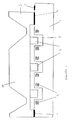
- Figure 1 is a micro-generator according to an example of the present invention;
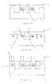
- Figures 2A to 2C are examples of different coil and magnet arrangements possible in the micro-generator shown in figure 1; and
- Figures 3A and 3B are an example transformers according to the present invention.
- Referring to claim 1, an example micro-generator according to the present invention comprises an integrated circuit (IC) chip 1 with a plurality of metal micro-coils 2 within the chip 1. The
coils 2 are realised as part of the IC chip 1 and are serially coupled. The micro-generator also comprises a microelectromechanical system (MEMS)chip 3 which includes an energy pick-up such as a mass-spring system 3a or a diaphragm (not shown). A plurality of micro-magnets 4 are formed on theMEMS chip 3 and a plurality oftrenches 5 are formed in the IC chip 1 to accommodate themagnets 4. Thecoils 2 andmagnets 4 are positioned within the IC chip 1 in such a way that themagnets 4 can move within thetrenches 5 close to thecoils 2 to induce a current in thecoils 2. In the example shown, themagnets 4 surround thetrenches 5. TheMEMS chip 3 and IC chip 1 are bonded together at the bond regions 6 shown in figure 1. Bond pads 7 are formed on the IC chip 1. - Figures 2A to 2C show
alternative coil 2,magnet 4 andtrench 5 arrangements to that shown in figure 1. In figure 2A amagnet 4 is isolated by means of anempty trench 5 either side of thetrench 5 occupied by themagnet 4. This helps reduce parasitics and other losses. In figure 2B losses are reduced by means ofmetal shields 8 in betweencoils 2. In figure 2C losses are reduced by means of further trenches 9 formed in theMEMS chip 3 adjacent tocoils 2. - Referring to figure 3A, an example micro-transformer according to the present invention has the same form as the micro-generator described above. An
example magnet 4 is shown which is accommodated in atrench 5 such that themagnet 4 can move within thetrench 5. A set ofprimary coils 10 surround themagnet 4 and a set ofsecondary coils 11 surround theprimary coils 10, thesecondary coils 11 having more turns than the primary coils. In this way the voltage generated by a micro-generator can be increased to a level required for the application to be powered by the micro-generator. Figure 3B shows an alternative arrangement of the example of figure 3A. In this arrangement there is still provided a set ofprimary coils 10 and a set ofsecondary coils 11, although the two are positioned above one another and interlaced. Generally theprimary coil 10 will have fewer turns (layers) than thesecondary coil 11, although the actual number and relative proportions of primary and secondary coils will be dependent upon the particular application and the voltage transformation that is required. Such micro-transformers can be used in conjunction with a micro-generator according to the present invention. The transformer can be placed very close to the voltage to be increased to minimise losses. - The micro-generator of the present invention, preferably in combination with the micro-transformer of the preset invention, can be used in systems in environments experiencing mechanical vibrations or other dynamic mechanical loads. The micro-generator extracts power from the environment by using the relative motion of
magnets 4 andcoils 2 caused by the mechanical load. In operation of the example shown in figure 1, the mass-spring system 3a which is the energy pick-up moves as a result of an external mechanical load and so causes themagnets 4 to move within thetrenches 5 to induce a current in thecoils 2. If the transformer of figures 3A and B is used, a current is induced in theprimary coils 10 which is increased by thesecondary coils 11. - The energy pick-up 3a has a large sensitivity and moves like a large stiff body which ensures both a large amplitude and the same phase for power generation in each of the serially coupled
coils 2. - The example micro-generator shown in figure 1 is manufactured by making the serially coupled
coils 2 from aluminium or copper in an IC wafer by using the advanced multilayer IC process.Trenches 5 are then made in the IC wafer by means of deep reactive ion etching (DRIE) to allow formagnets 4 to move near thecoils 2. A thin film layer of magnetic material such as NiFe8l/19 is formed on a MEMS wafer, for example by sputtering or electroplating. This is patterned and etched to form the micro-magnets 4. The MEMS wafer includes the energy pick-ups. The MEMS wafer is then bonded to the IC wafer and the resulting wafer is diced to form micro-generators as shown in figure 1. - The invention makes use of "large" mechanical members for the energy pick-up, such as inertia masses 3a and diaphragms, to maximise energy pick-up, but these are still used at the die level by using the approach of combining MEMS and lC technology. As standard complementary metal oxide semiconductor (CMOS) or Biplor CMOS (BiCMOS) IC technology is part of the micro-generation system, combining the micro-generator with a device to be powered is straightforward and low cost.
Claims (9)
- A micro-generator comprising:an integrated circuit (IC) wafer;a microelectromechanical system (MEMS) wafer bonded to the IC wafer, the MEMS wafer comprising a micromechanical element arranged to move in use;a plurality of first metal coils, the coils being realized as part of the lC wafer and/or the MEMS wafer;a plurality of trenches formed in the lC wafer and/or the MEMS wafer and associated with the first coils;a plurality of micro-magnets, a micro-magnet being associated with each trench, wherein the micro-magnets are formed from a magnet layer deposited or platedor bonded to the MEMS wafer and/or the IC wafer;
wherein upon movement of the micromechanical element in use, the micro-magnets are arranged to move within the trenches relative to the first coils such that a voltage is induced in the first coils. - A micro-generator according to claim 1, further comprising isolation means arranged to isolate adjacent micro-magnets in use.
- A micro-transformer for a micro-generator, the transformer comprising:a plurality of first metal coils and a plurality of second metal coils associated with the first coils, the first and second coils being realized as part of an IC or MEMS wafer, a first voltage being induceable in the first coils in use by the micro-generator; magnetic material realized as part of an IC or MEMS wafer;wherein the coils and magnetic material are arranged such that a first voltage induced in use in the first coils causes a second voltage to be induced in the second coils, wherein the second voltage is larger than the first voltage.
- A micro-generation system comprising a micro-generator according to claim 1 or claim and a micro-transformer according to claim 3.
- A method of manufacturing a micro-generator, the method comprising the steps of:forming a plurality of first metal coils as part of an integrated circuit (lC) wafer and/or MEMS wafer, the MEMS wafer comprising a micromechanical element arranged to move in use;forming a plurality of trenches associated with the first coils in the IC wafer and/or MEMS wafer;forming a layer of magnetic material on the MEMS wafer and/or the IC wafer; forming a plurality of micro-magnets from the magnetic layer, a micro-magnet being associated with each trench;bonding the MEMS wafer to the IC wafer to define a micro-generator wafer such that in use, on movement of the micromechanical element, the micro-magnets move within the trenches relative to the metal coils such that a voltage is induced in the first coils;dicing the micro-generator wafer to form individual micro-generators.
- A method of manufacturing a micro-generator according to claim 5, wherein the plurality of first metal coils are formed in the IC wafer by a multilayer IC process.
- A method of manufacturing a micro-generator according to claim 5 or claim 6, wherein the trenches are formed by deep reactive ion etching.
- A method of manufacturing a micro-generator according to any of claims 4 to 6, wherein the layer of magnetic material is formed by deposition, plating or bonding.
- A method of manufacturing a micro-generator according to any of claims 4 to 7, wherein the micro-magnets are forming by etching or abbreviating the magnetic layer.
Priority Applications (3)
| Application Number | Priority Date | Filing Date | Title |
|---|---|---|---|
| EP06111810A EP1841049B1 (en) | 2006-03-28 | 2006-03-28 | Electromagnetic micro-generator |
| US11/685,031 US7501302B2 (en) | 2006-03-28 | 2007-03-12 | Electromagnetic micro-generator and method for manufacturing the same |
| JP2007074492A JP2007267590A (en) | 2006-03-28 | 2007-03-22 | Electromagnetic micro generator |
Applications Claiming Priority (1)
| Application Number | Priority Date | Filing Date | Title |
|---|---|---|---|
| EP06111810A EP1841049B1 (en) | 2006-03-28 | 2006-03-28 | Electromagnetic micro-generator |
Publications (2)
| Publication Number | Publication Date |
|---|---|
| EP1841049A1 true EP1841049A1 (en) | 2007-10-03 |
| EP1841049B1 EP1841049B1 (en) | 2012-08-15 |
Family
ID=36825472
Family Applications (1)
| Application Number | Title | Priority Date | Filing Date |
|---|---|---|---|
| EP06111810A Ceased EP1841049B1 (en) | 2006-03-28 | 2006-03-28 | Electromagnetic micro-generator |
Country Status (3)
| Country | Link |
|---|---|
| US (1) | US7501302B2 (en) |
| EP (1) | EP1841049B1 (en) |
| JP (1) | JP2007267590A (en) |
Cited By (2)
| Publication number | Priority date | Publication date | Assignee | Title |
|---|---|---|---|---|
| US7498681B1 (en) * | 2007-03-21 | 2009-03-03 | Sandia Corporation | Mechanical vibration to electrical energy converter |
| EP2404371A4 (en) * | 2009-03-06 | 2013-12-25 | Lumedyne Technologies Inc | An apparatus for generating power responsive to mechanical vibration |
Families Citing this family (11)
| Publication number | Priority date | Publication date | Assignee | Title |
|---|---|---|---|---|
| FR2903807B1 (en) * | 2006-07-12 | 2009-10-09 | Schneider Electric Ind Sas | SWITCHING DEVICE INCLUDING A MOBILE FERROMAGNETIC PART |
| JP5668247B2 (en) * | 2007-11-30 | 2015-02-12 | セイコーインスツル株式会社 | Vibration current converter |
| KR100952177B1 (en) | 2007-11-30 | 2010-04-09 | 가톨릭대학교 산학협력단 | MEMS-based electromagnetic induction generator and its manufacturing method |
| WO2010000316A1 (en) * | 2008-07-02 | 2010-01-07 | Lightlite Gmbh | Electric motor-driven linear generator |
| US8390137B2 (en) * | 2009-10-01 | 2013-03-05 | Mark Bryfogle | Fluid-driven electrical generator |
| CN103208899B (en) * | 2012-01-16 | 2016-02-17 | 曾胜克 | power generation device |
| ITTO20120290A1 (en) | 2012-04-02 | 2013-10-03 | St Microelectronics Srl | INERTIAL MAGNETIC SENSOR, AND METHOD FOR OPERATING THE INERTIAL SENSOR |
| DE102014119089A1 (en) * | 2014-12-18 | 2016-06-23 | Antonio Chiriatti | Voltage generator |
| US10280070B2 (en) | 2015-09-30 | 2019-05-07 | Stmicroelectronics S.R.L. | Magnetic inertial sensor energy harvesting and scavenging methods, circuits and systems |
| DE102017123397B3 (en) * | 2017-10-09 | 2018-06-28 | Airbus Defence and Space GmbH | Passive protection against radiation |
| US10868479B2 (en) * | 2018-10-04 | 2020-12-15 | Stmicroelectronics S.R.L. | Inverse electrowetting and magnetic energy harvesting and scavenging methods, circuits and systems |
Citations (3)
| Publication number | Priority date | Publication date | Assignee | Title |
|---|---|---|---|---|
| JPH07263230A (en) * | 1994-03-25 | 1995-10-13 | Takeshi Ikeda | Miniature transformer |
| JP2002262545A (en) * | 2001-02-28 | 2002-09-13 | Toshiba Corp | Semiconductor device |
| US20040246647A1 (en) * | 2003-03-07 | 2004-12-09 | Infineon Technologies Ag | Monolithic integrated circuit arrangement |
Family Cites Families (2)
| Publication number | Priority date | Publication date | Assignee | Title |
|---|---|---|---|---|
| US6083802A (en) * | 1998-12-31 | 2000-07-04 | Winbond Electronics Corporation | Method for forming an inductor |
| US6667536B2 (en) * | 2001-06-28 | 2003-12-23 | Agere Systems Inc. | Thin film multi-layer high Q transformer formed in a semiconductor substrate |
-
2006
- 2006-03-28 EP EP06111810A patent/EP1841049B1/en not_active Ceased
-
2007
- 2007-03-12 US US11/685,031 patent/US7501302B2/en not_active Expired - Fee Related
- 2007-03-22 JP JP2007074492A patent/JP2007267590A/en active Pending
Patent Citations (3)
| Publication number | Priority date | Publication date | Assignee | Title |
|---|---|---|---|---|
| JPH07263230A (en) * | 1994-03-25 | 1995-10-13 | Takeshi Ikeda | Miniature transformer |
| JP2002262545A (en) * | 2001-02-28 | 2002-09-13 | Toshiba Corp | Semiconductor device |
| US20040246647A1 (en) * | 2003-03-07 | 2004-12-09 | Infineon Technologies Ag | Monolithic integrated circuit arrangement |
Non-Patent Citations (10)
| Title |
|---|
| CHING N N H ET AL: "A laser-micromachined multi-modal resonating power transducer for wireless sensing systems", SENSORS AND ACTUATORS A, ELSEVIER SEQUOIA S.A., LAUSANNE, CH, vol. 97-98, 1 April 2002 (2002-04-01), pages 685 - 690, XP004361667, ISSN: 0924-4247 * |
| LI W J ET AL: "Infrared signal transmission by a laser-micromachined vibration-induced power generator", CIRCUITS AND SYSTEMS, 2000. PROCEEDINGS OF THE 43RD IEEE MIDWEST SYMPOSIUM ON AUGUST 8-11, 2000, PISCATAWAY, NJ, USA,IEEE, vol. 1, 8 August 2000 (2000-08-08), pages 236 - 239, XP010558118, ISBN: 0-7803-6475-9 * |
| M. MINO ET AL: "Planar Microtransformer with monolithically-integrated Rectifier Diodes For Micro-Switching Converters", IEEE TRANSACTIONS ON MAGNETICS, vol. 32, no. 2, March 1996 (1996-03-01), XP002396424 * |
| NEIL N. H. CHING ET AL: "PCB INTEGRATED MICRO-GENERATOR FOR WIRELESS SYSTEMS", PROCEEDINGS OF THE INTERNATIONAL SYMPOSIUM ON SMART STRRUCTURES AND MICROSYSTEMS, October 2000 (2000-10-01), XP002396422 * |
| PATENT ABSTRACTS OF JAPAN vol. 1996, no. 02 29 February 1996 (1996-02-29) * |
| PATENT ABSTRACTS OF JAPAN vol. 2003, no. 01 14 January 2003 (2003-01-14) * |
| S.P. BEEPY ET AL: "DESIGN, FABRICATION AND SIMULATIONS OF MICROELECTROMAGNETIC VIBRATION-POWERED GENERATOR FOR LOW POWER MEMS", DTIP OF MEMS & MOEMS, June 2005 (2005-06-01), XP002396421 * |
| SARAH SCHERRER ET AL: "Energy scavenging Device in LTCC Materials", IEEE WORKSHOP ON MICROELECTRONICS AND ELECTRON DEVICES, 2005, pages 77 - 78, XP002396419 * |
| SHEARWOOD C ET AL: "Development of an electromagnetic micro-generator", ELECTRONICS LETTERS, IEE STEVENAGE, GB, vol. 33, no. 22, 23 October 1997 (1997-10-23), pages 1883 - 1884, XP006008104, ISSN: 0013-5194 * |
| WAGNER B ET AL: "Microfabricated actuator with moving permanent magnet", PROCEEDINGS OF THE WORKSHOP ON MICRO ELECTRO MECHANICAL SYSTEMS. INVESTIGATION OF MICRO STRUCTURES, SENSORS, ACTUATORS, MACHINES AND ROBOTS. NARA, JP., JAN. 30 - FEB. 2, 1991, NEW YORK, IEEE, US, vol. WORKSHOP 4, 30 January 1991 (1991-01-30), pages 27 - 32, XP010039601, ISBN: 0-87942-641-1 * |
Cited By (2)
| Publication number | Priority date | Publication date | Assignee | Title |
|---|---|---|---|---|
| US7498681B1 (en) * | 2007-03-21 | 2009-03-03 | Sandia Corporation | Mechanical vibration to electrical energy converter |
| EP2404371A4 (en) * | 2009-03-06 | 2013-12-25 | Lumedyne Technologies Inc | An apparatus for generating power responsive to mechanical vibration |
Also Published As
| Publication number | Publication date |
|---|---|
| US20070231944A1 (en) | 2007-10-04 |
| EP1841049B1 (en) | 2012-08-15 |
| US7501302B2 (en) | 2009-03-10 |
| JP2007267590A (en) | 2007-10-11 |
Similar Documents
| Publication | Publication Date | Title |
|---|---|---|
| US7501302B2 (en) | Electromagnetic micro-generator and method for manufacturing the same | |
| CN102610588B (en) | Semiconductor device and manufacture method thereof, method for signal transmission | |
| JP5705857B2 (en) | Micro-coil device and manufacturing method thereof | |
| US8763220B2 (en) | Method of manufacturing a MEMS device | |
| JP5424379B2 (en) | Vibration current converter | |
| US20120168901A1 (en) | Semiconductor electronic device with an integrated device with an integrated galvanic isolator element and related assembly process | |
| US20170141668A1 (en) | Chip-scale electromagnetic vibrational energy harvester | |
| US20100255623A1 (en) | Packaging and Connecting Electrostatic Transducer Arrays | |
| US8665041B2 (en) | Integrated microminiature relay | |
| JP4275550B2 (en) | Monolithic integrated circuit structure | |
| US20120139389A1 (en) | Microelectronic devices for harvesting kinetic energy and associated systems and methods | |
| Williams et al. | Microfabrication of an electromagnetic power relay using SU-8 based UV-LIGA technology | |
| JP2013126337A (en) | Power generation device | |
| KR101458265B1 (en) | An apparatus for generating power responsive to mechanical vibration | |
| JP2012520053A5 (en) | ||
| CN112583227B (en) | MEMS inductive vibration energy collector and preparation method thereof | |
| Sun et al. | A MEMS Voice Coil Motor with a 3D Solenoid Coil | |
| JP5668247B2 (en) | Vibration current converter | |
| WO2005043602A2 (en) | Three-dimensional inductive micro components | |
| EP3393966A1 (en) | A method for manufacturing a hollow mems structure | |
| WO1998034287A9 (en) | Vialess integrated inductive elements for electromagnetic applications | |
| WO1998034287A1 (en) | Vialess integrated inductive elements for electromagnetic applications |
Legal Events
| Date | Code | Title | Description |
|---|---|---|---|
| PUAI | Public reference made under article 153(3) epc to a published international application that has entered the european phase |
Free format text: ORIGINAL CODE: 0009012 |
|
| AK | Designated contracting states |
Kind code of ref document: A1 Designated state(s): AT BE BG CH CY CZ DE DK EE ES FI FR GB GR HU IE IS IT LI LT LU LV MC NL PL PT RO SE SI SK TR |
|
| AX | Request for extension of the european patent |
Extension state: AL BA HR MK YU |
|
| 17P | Request for examination filed |
Effective date: 20080311 |
|
| 17Q | First examination report despatched |
Effective date: 20080506 |
|
| AKX | Designation fees paid |
Designated state(s): DE |
|
| RAP1 | Party data changed (applicant data changed or rights of an application transferred) |
Owner name: INFINEON TECHNOLOGIES AG |
|
| GRAP | Despatch of communication of intention to grant a patent |
Free format text: ORIGINAL CODE: EPIDOSNIGR1 |
|
| GRAS | Grant fee paid |
Free format text: ORIGINAL CODE: EPIDOSNIGR3 |
|
| GRAA | (expected) grant |
Free format text: ORIGINAL CODE: 0009210 |
|
| AK | Designated contracting states |
Kind code of ref document: B1 Designated state(s): DE |
|
| REG | Reference to a national code |
Ref country code: DE Ref legal event code: R096 Ref document number: 602006031381 Country of ref document: DE Effective date: 20121018 |
|
| PLBE | No opposition filed within time limit |
Free format text: ORIGINAL CODE: 0009261 |
|
| STAA | Information on the status of an ep patent application or granted ep patent |
Free format text: STATUS: NO OPPOSITION FILED WITHIN TIME LIMIT |
|
| 26N | No opposition filed |
Effective date: 20130516 |
|
| REG | Reference to a national code |
Ref country code: DE Ref legal event code: R097 Ref document number: 602006031381 Country of ref document: DE Effective date: 20130516 |
|
| PGFP | Annual fee paid to national office [announced via postgrant information from national office to epo] |
Ref country code: DE Payment date: 20190528 Year of fee payment: 14 |
|
| REG | Reference to a national code |
Ref country code: DE Ref legal event code: R119 Ref document number: 602006031381 Country of ref document: DE |
|
| PG25 | Lapsed in a contracting state [announced via postgrant information from national office to epo] |
Ref country code: DE Free format text: LAPSE BECAUSE OF NON-PAYMENT OF DUE FEES Effective date: 20201001 |