EP1841044A2 - Lessivage des plaques dýassemblage - Google Patents
Lessivage des plaques dýassemblage Download PDFInfo
- Publication number
- EP1841044A2 EP1841044A2 EP07075547A EP07075547A EP1841044A2 EP 1841044 A2 EP1841044 A2 EP 1841044A2 EP 07075547 A EP07075547 A EP 07075547A EP 07075547 A EP07075547 A EP 07075547A EP 1841044 A2 EP1841044 A2 EP 1841044A2
- Authority
- EP
- European Patent Office
- Prior art keywords
- axial
- conveying part
- fluid
- hub
- rotor
- Prior art date
- Legal status (The legal status is an assumption and is not a legal conclusion. Google has not performed a legal analysis and makes no representation as to the accuracy of the status listed.)
- Granted
Links
Images


Classifications
-
- F—MECHANICAL ENGINEERING; LIGHTING; HEATING; WEAPONS; BLASTING
- F16—ENGINEERING ELEMENTS AND UNITS; GENERAL MEASURES FOR PRODUCING AND MAINTAINING EFFECTIVE FUNCTIONING OF MACHINES OR INSTALLATIONS; THERMAL INSULATION IN GENERAL
- F16C—SHAFTS; FLEXIBLE SHAFTS; ELEMENTS OR CRANKSHAFT MECHANISMS; ROTARY BODIES OTHER THAN GEARING ELEMENTS; BEARINGS
- F16C32/00—Bearings not otherwise provided for
- F16C32/04—Bearings not otherwise provided for using magnetic or electric supporting means
- F16C32/0406—Magnetic bearings
- F16C32/044—Active magnetic bearings
-
- A—HUMAN NECESSITIES
- A61—MEDICAL OR VETERINARY SCIENCE; HYGIENE
- A61M—DEVICES FOR INTRODUCING MEDIA INTO, OR ONTO, THE BODY; DEVICES FOR TRANSDUCING BODY MEDIA OR FOR TAKING MEDIA FROM THE BODY; DEVICES FOR PRODUCING OR ENDING SLEEP OR STUPOR
- A61M60/00—Blood pumps; Devices for mechanical circulatory actuation; Balloon pumps for circulatory assistance
- A61M60/10—Location thereof with respect to the patient's body
- A61M60/122—Implantable pumps or pumping devices, i.e. the blood being pumped inside the patient's body
- A61M60/165—Implantable pumps or pumping devices, i.e. the blood being pumped inside the patient's body implantable in, on, or around the heart
- A61M60/178—Implantable pumps or pumping devices, i.e. the blood being pumped inside the patient's body implantable in, on, or around the heart drawing blood from a ventricle and returning the blood to the arterial system via a cannula external to the ventricle, e.g. left or right ventricular assist devices
-
- A—HUMAN NECESSITIES
- A61—MEDICAL OR VETERINARY SCIENCE; HYGIENE
- A61M—DEVICES FOR INTRODUCING MEDIA INTO, OR ONTO, THE BODY; DEVICES FOR TRANSDUCING BODY MEDIA OR FOR TAKING MEDIA FROM THE BODY; DEVICES FOR PRODUCING OR ENDING SLEEP OR STUPOR
- A61M60/00—Blood pumps; Devices for mechanical circulatory actuation; Balloon pumps for circulatory assistance
- A61M60/20—Type thereof
- A61M60/205—Non-positive displacement blood pumps
- A61M60/216—Non-positive displacement blood pumps including a rotating member acting on the blood, e.g. impeller
- A61M60/237—Non-positive displacement blood pumps including a rotating member acting on the blood, e.g. impeller the blood flow through the rotating member having mainly axial components, e.g. axial flow pumps
-
- A—HUMAN NECESSITIES
- A61—MEDICAL OR VETERINARY SCIENCE; HYGIENE
- A61M—DEVICES FOR INTRODUCING MEDIA INTO, OR ONTO, THE BODY; DEVICES FOR TRANSDUCING BODY MEDIA OR FOR TAKING MEDIA FROM THE BODY; DEVICES FOR PRODUCING OR ENDING SLEEP OR STUPOR
- A61M60/00—Blood pumps; Devices for mechanical circulatory actuation; Balloon pumps for circulatory assistance
- A61M60/40—Details relating to driving
- A61M60/403—Details relating to driving for non-positive displacement blood pumps
- A61M60/422—Details relating to driving for non-positive displacement blood pumps the force acting on the blood contacting member being electromagnetic, e.g. using canned motor pumps
-
- A—HUMAN NECESSITIES
- A61—MEDICAL OR VETERINARY SCIENCE; HYGIENE
- A61M—DEVICES FOR INTRODUCING MEDIA INTO, OR ONTO, THE BODY; DEVICES FOR TRANSDUCING BODY MEDIA OR FOR TAKING MEDIA FROM THE BODY; DEVICES FOR PRODUCING OR ENDING SLEEP OR STUPOR
- A61M60/00—Blood pumps; Devices for mechanical circulatory actuation; Balloon pumps for circulatory assistance
- A61M60/50—Details relating to control
- A61M60/508—Electronic control means, e.g. for feedback regulation
- A61M60/538—Regulation using real-time blood pump operational parameter data, e.g. motor current
-
- A—HUMAN NECESSITIES
- A61—MEDICAL OR VETERINARY SCIENCE; HYGIENE
- A61M—DEVICES FOR INTRODUCING MEDIA INTO, OR ONTO, THE BODY; DEVICES FOR TRANSDUCING BODY MEDIA OR FOR TAKING MEDIA FROM THE BODY; DEVICES FOR PRODUCING OR ENDING SLEEP OR STUPOR
- A61M60/00—Blood pumps; Devices for mechanical circulatory actuation; Balloon pumps for circulatory assistance
- A61M60/80—Constructional details other than related to driving
- A61M60/802—Constructional details other than related to driving of non-positive displacement blood pumps
- A61M60/81—Pump housings
- A61M60/812—Vanes or blades, e.g. static flow guides
-
- A—HUMAN NECESSITIES
- A61—MEDICAL OR VETERINARY SCIENCE; HYGIENE
- A61M—DEVICES FOR INTRODUCING MEDIA INTO, OR ONTO, THE BODY; DEVICES FOR TRANSDUCING BODY MEDIA OR FOR TAKING MEDIA FROM THE BODY; DEVICES FOR PRODUCING OR ENDING SLEEP OR STUPOR
- A61M60/00—Blood pumps; Devices for mechanical circulatory actuation; Balloon pumps for circulatory assistance
- A61M60/80—Constructional details other than related to driving
- A61M60/802—Constructional details other than related to driving of non-positive displacement blood pumps
- A61M60/818—Bearings
- A61M60/82—Magnetic bearings
- A61M60/822—Magnetic bearings specially adapted for being actively controlled
-
- F—MECHANICAL ENGINEERING; LIGHTING; HEATING; WEAPONS; BLASTING
- F04—POSITIVE - DISPLACEMENT MACHINES FOR LIQUIDS; PUMPS FOR LIQUIDS OR ELASTIC FLUIDS
- F04D—NON-POSITIVE-DISPLACEMENT PUMPS
- F04D13/00—Pumping installations or systems
- F04D13/02—Units comprising pumps and their driving means
- F04D13/06—Units comprising pumps and their driving means the pump being electrically driven
- F04D13/0606—Canned motor pumps
- F04D13/0633—Details of the bearings
-
- F—MECHANICAL ENGINEERING; LIGHTING; HEATING; WEAPONS; BLASTING
- F04—POSITIVE - DISPLACEMENT MACHINES FOR LIQUIDS; PUMPS FOR LIQUIDS OR ELASTIC FLUIDS
- F04D—NON-POSITIVE-DISPLACEMENT PUMPS
- F04D13/00—Pumping installations or systems
- F04D13/02—Units comprising pumps and their driving means
- F04D13/06—Units comprising pumps and their driving means the pump being electrically driven
- F04D13/0606—Canned motor pumps
- F04D13/064—Details of the magnetic circuit
-
- F—MECHANICAL ENGINEERING; LIGHTING; HEATING; WEAPONS; BLASTING
- F04—POSITIVE - DISPLACEMENT MACHINES FOR LIQUIDS; PUMPS FOR LIQUIDS OR ELASTIC FLUIDS
- F04D—NON-POSITIVE-DISPLACEMENT PUMPS
- F04D15/00—Control, e.g. regulation, of pumps, pumping installations or systems
-
- F—MECHANICAL ENGINEERING; LIGHTING; HEATING; WEAPONS; BLASTING
- F04—POSITIVE - DISPLACEMENT MACHINES FOR LIQUIDS; PUMPS FOR LIQUIDS OR ELASTIC FLUIDS
- F04D—NON-POSITIVE-DISPLACEMENT PUMPS
- F04D29/00—Details, component parts, or accessories
- F04D29/04—Shafts or bearings, or assemblies thereof
- F04D29/041—Axial thrust balancing
- F04D29/0413—Axial thrust balancing hydrostatic; hydrodynamic thrust bearings
-
- F—MECHANICAL ENGINEERING; LIGHTING; HEATING; WEAPONS; BLASTING
- F04—POSITIVE - DISPLACEMENT MACHINES FOR LIQUIDS; PUMPS FOR LIQUIDS OR ELASTIC FLUIDS
- F04D—NON-POSITIVE-DISPLACEMENT PUMPS
- F04D3/00—Axial-flow pumps
- F04D3/02—Axial-flow pumps of screw type
-
- F—MECHANICAL ENGINEERING; LIGHTING; HEATING; WEAPONS; BLASTING
- F16—ENGINEERING ELEMENTS AND UNITS; GENERAL MEASURES FOR PRODUCING AND MAINTAINING EFFECTIVE FUNCTIONING OF MACHINES OR INSTALLATIONS; THERMAL INSULATION IN GENERAL
- F16C—SHAFTS; FLEXIBLE SHAFTS; ELEMENTS OR CRANKSHAFT MECHANISMS; ROTARY BODIES OTHER THAN GEARING ELEMENTS; BEARINGS
- F16C39/00—Relieving load on bearings
- F16C39/06—Relieving load on bearings using magnetic means
- F16C39/063—Permanent magnets
-
- H—ELECTRICITY
- H02—GENERATION; CONVERSION OR DISTRIBUTION OF ELECTRIC POWER
- H02K—DYNAMO-ELECTRIC MACHINES
- H02K11/00—Structural association of dynamo-electric machines with electric components or with devices for shielding, monitoring or protection
- H02K11/20—Structural association of dynamo-electric machines with electric components or with devices for shielding, monitoring or protection for measuring, monitoring, testing, protecting or switching
-
- H—ELECTRICITY
- H02—GENERATION; CONVERSION OR DISTRIBUTION OF ELECTRIC POWER
- H02K—DYNAMO-ELECTRIC MACHINES
- H02K5/00—Casings; Enclosures; Supports
- H02K5/04—Casings or enclosures characterised by the shape, form or construction thereof
- H02K5/12—Casings or enclosures characterised by the shape, form or construction thereof specially adapted for operating in liquid or gas
- H02K5/128—Casings or enclosures characterised by the shape, form or construction thereof specially adapted for operating in liquid or gas using air-gap sleeves or air-gap discs
-
- H—ELECTRICITY
- H02—GENERATION; CONVERSION OR DISTRIBUTION OF ELECTRIC POWER
- H02K—DYNAMO-ELECTRIC MACHINES
- H02K7/00—Arrangements for handling mechanical energy structurally associated with dynamo-electric machines, e.g. structural association with mechanical driving motors or auxiliary dynamo-electric machines
- H02K7/08—Structural association with bearings
- H02K7/09—Structural association with bearings with magnetic bearings
-
- H—ELECTRICITY
- H02—GENERATION; CONVERSION OR DISTRIBUTION OF ELECTRIC POWER
- H02K—DYNAMO-ELECTRIC MACHINES
- H02K7/00—Arrangements for handling mechanical energy structurally associated with dynamo-electric machines, e.g. structural association with mechanical driving motors or auxiliary dynamo-electric machines
- H02K7/14—Structural association with mechanical loads, e.g. with hand-held machine tools or fans
-
- A—HUMAN NECESSITIES
- A61—MEDICAL OR VETERINARY SCIENCE; HYGIENE
- A61M—DEVICES FOR INTRODUCING MEDIA INTO, OR ONTO, THE BODY; DEVICES FOR TRANSDUCING BODY MEDIA OR FOR TAKING MEDIA FROM THE BODY; DEVICES FOR PRODUCING OR ENDING SLEEP OR STUPOR
- A61M1/00—Suction or pumping devices for medical purposes; Devices for carrying-off, for treatment of, or for carrying-over, body-liquids; Drainage systems
- A61M1/36—Other treatment of blood in a by-pass of the natural circulatory system, e.g. temperature adaptation, irradiation ; Extra-corporeal blood circuits
- A61M1/3621—Extra-corporeal blood circuits
- A61M1/3639—Blood pressure control, pressure transducers specially adapted therefor
-
- A—HUMAN NECESSITIES
- A61—MEDICAL OR VETERINARY SCIENCE; HYGIENE
- A61M—DEVICES FOR INTRODUCING MEDIA INTO, OR ONTO, THE BODY; DEVICES FOR TRANSDUCING BODY MEDIA OR FOR TAKING MEDIA FROM THE BODY; DEVICES FOR PRODUCING OR ENDING SLEEP OR STUPOR
- A61M2205/00—General characteristics of the apparatus
- A61M2205/33—Controlling, regulating or measuring
- A61M2205/3331—Pressure; Flow
- A61M2205/3351—Controlling upstream pump pressure
-
- A—HUMAN NECESSITIES
- A61—MEDICAL OR VETERINARY SCIENCE; HYGIENE
- A61M—DEVICES FOR INTRODUCING MEDIA INTO, OR ONTO, THE BODY; DEVICES FOR TRANSDUCING BODY MEDIA OR FOR TAKING MEDIA FROM THE BODY; DEVICES FOR PRODUCING OR ENDING SLEEP OR STUPOR
- A61M60/00—Blood pumps; Devices for mechanical circulatory actuation; Balloon pumps for circulatory assistance
- A61M60/10—Location thereof with respect to the patient's body
- A61M60/122—Implantable pumps or pumping devices, i.e. the blood being pumped inside the patient's body
- A61M60/126—Implantable pumps or pumping devices, i.e. the blood being pumped inside the patient's body implantable via, into, inside, in line, branching on, or around a blood vessel
- A61M60/148—Implantable pumps or pumping devices, i.e. the blood being pumped inside the patient's body implantable via, into, inside, in line, branching on, or around a blood vessel in line with a blood vessel using resection or like techniques, e.g. permanent endovascular heart assist devices
-
- A—HUMAN NECESSITIES
- A61—MEDICAL OR VETERINARY SCIENCE; HYGIENE
- A61M—DEVICES FOR INTRODUCING MEDIA INTO, OR ONTO, THE BODY; DEVICES FOR TRANSDUCING BODY MEDIA OR FOR TAKING MEDIA FROM THE BODY; DEVICES FOR PRODUCING OR ENDING SLEEP OR STUPOR
- A61M60/00—Blood pumps; Devices for mechanical circulatory actuation; Balloon pumps for circulatory assistance
- A61M60/80—Constructional details other than related to driving
- A61M60/802—Constructional details other than related to driving of non-positive displacement blood pumps
- A61M60/818—Bearings
- A61M60/824—Hydrodynamic or fluid film bearings
-
- F—MECHANICAL ENGINEERING; LIGHTING; HEATING; WEAPONS; BLASTING
- F16—ENGINEERING ELEMENTS AND UNITS; GENERAL MEASURES FOR PRODUCING AND MAINTAINING EFFECTIVE FUNCTIONING OF MACHINES OR INSTALLATIONS; THERMAL INSULATION IN GENERAL
- F16C—SHAFTS; FLEXIBLE SHAFTS; ELEMENTS OR CRANKSHAFT MECHANISMS; ROTARY BODIES OTHER THAN GEARING ELEMENTS; BEARINGS
- F16C2316/00—Apparatus in health or amusement
- F16C2316/10—Apparatus in health or amusement in medical appliances, e.g. in diagnosis, dentistry, instruments, prostheses, medical imaging appliances
- F16C2316/18—Pumps for pumping blood
-
- F—MECHANICAL ENGINEERING; LIGHTING; HEATING; WEAPONS; BLASTING
- F16—ENGINEERING ELEMENTS AND UNITS; GENERAL MEASURES FOR PRODUCING AND MAINTAINING EFFECTIVE FUNCTIONING OF MACHINES OR INSTALLATIONS; THERMAL INSULATION IN GENERAL
- F16C—SHAFTS; FLEXIBLE SHAFTS; ELEMENTS OR CRANKSHAFT MECHANISMS; ROTARY BODIES OTHER THAN GEARING ELEMENTS; BEARINGS
- F16C2360/00—Engines or pumps
- F16C2360/44—Centrifugal pumps
Definitions
- the invention relates to a device for gentle conveying of single- or multi-phase fluids according to the preamble of claim 1.
- a particularly sensitive fluid system is the blood.
- This opaque red body fluid of the vertebrates circulates in a self-contained vascular system, with rhythmic contractions of the heart pushing the blood into the various areas of the organism.
- the blood transports the respiratory gases oxygen and carbon dioxide as well as nutrients, metabolites and endogenous agents.
- the blood vessel system, including the heart is hermetically shielded from the environment, so that in the healthy organism, the blood undergoes no changes when it is pumped through the heart through the body.
- Hemolysis describes the condition that beyond the physiological level the red blood cells within the body are lysed - destroyed. The causes of hemolysis can be mechanical or metabolic. Increased hemolysis causes multiple organ damage and can lead to death of the person.
- Heart support pumps and artificial hearts can be based on the required pressure difference and the volume flow be carried out both according to the displacement principle as so-called pulsatile pumps or according to the turbo principle as radial or axial flow machines. These three types are currently being developed in parallel.
- the turbomachinery show smaller dimensions than piston engines because of the high power density of this type of machine.
- the axial pump variant is usually smaller than the radial one.
- a turbomachine for a given pressure difference and given volume flow can be executed very differently both as an axial and a radial pump with very different rotational speeds.
- the known from the prior art axial blood pump essentially consist of an outer cylindrical tube in which a conveying part, which is designed as a rotor of an externally applied Motorstators, rotates and thus moves the blood in the axial direction.
- the storage of the conveyor part was a problem.
- a purely mechanical storage is disadvantageous in terms of blood damage and also the relatively high friction values.
- the magnetic bearing variants described so far have not led to a satisfactory solution.
- a generic axial blood pump for assisting a diseased heart which is implantable in the chest cavity of a patient.
- the axial blood pump has a rotating impeller with a blading inside a blood-carrying tube stored and driven by an electric motor.
- the impeller is designed as a rotor of the electric motor and coupled via mounted in the blading magnets with the housing-fixed stator of the electric motor.
- Such an arrangement is also known from US Pat. No. 4,957,504 known.
- the known blood pump has the disadvantage that the pumped blood undergoes traumatic injury and injury to a considerable extent. In particular, there is a risk of thrombus formation. The reason for this lies mainly in the formation of dead water areas at the camps.
- An implantable axial blood pump which consists of an outer cylindrical tube and a rotor hub rotating in this tube for blood delivery.
- the rotor is magnetically supported and at the same time carries the rotor magnets of the drive and the rotor blades.
- the magnetically mounted rotor forms long, narrow gaps with the stator blading attached to the outer tube.
- FIG. 97/49440 Another axial blood pump with magnetic storage is off WO 97/49440 known.
- the magnetic bearing takes place at the conically shaped rotor ends of the rotor, which forms the impeller.
- the rotor ends face fixed pole shoes which guide the flow of permanent magnets.
- Storage requires active stabilization with at least four stabilizer coils in both the axial and radial directions.
- Bearings with radially magnetized permanent magnet rings proposed with alternating magnetization direction, which are technically difficult to control.
- the "bearingless" motor is a combination of motor and magnetic bearing.
- the position of the rotor is passively stabilized by permanent magnets with respect to three degrees of freedom - translation in the x direction, tilting in the x and y directions.
- the passive stabilization is realized by a permanent magnetic rotor ring, which is surrounded on the stator side by a soft iron ring. Control and drive windings, which are connected to the soft iron ring, allow a control with respect to three degrees of freedom.
- the low bearing stiffness requires additional measures.
- a position stabilization in the x and y direction is necessary, which leads to a high metrological effort and can cause high heating of the pump by the active coils.
- the conveying part is magnetically supported there between two fastening parts, which are fastened in a tubular hollow body while leaving an annular gap.
- the conveying part forms the rotor of a motor whose stator is arranged outside the tubular hollow body.
- the magnetic bearing takes place in the radial direction with radially magnetized permanent magnets and, as far as possible decoupled, in the axial direction.
- electromagnetic coils Radially magnetized permanent magnets require a certain minimum size and small air gaps.
- the conveying gap may therefore only be very small, which is not a hindrance to the present conveying task (screw pumps produce a high pressure with a small delivery volume), but is not acceptable for other pumps, in particular blood pumps.
- the total axial rigidity which is very high compared to the radial stiffness due to the delivery pressure of the medium to be conveyed, must be applied by the stabilizing coils, which requires a certain amount of current, which leads to corresponding energy demand and heating.
- the control of the axial position is also carrier with increasing current level, so that the pump is only partially suitable for pulsatile conveying tasks.
- a generic object is in the US-A-5211546 disclosed.
- This is a suitable as a heart pump device for the gentle promotion of fluids, consisting of a tubular, the fluid substantially axially leading hollow body in which in axial alignment with a located outside the hollow body motor stator in rotation displaceable conveyor part is mounted.
- a fastening element In front of and behind the conveyor part, a fastening element is arranged, wherein in each case two fastening elements an axially extending bore is arranged, which is flowed through by the fluid to be pumped and causes the fluid located in the hub gap to prevent dead water areas is additionally transported radially.
- Problematic is the axial stabilization of this article.
- the invention has for its object to provide a device for the careful promotion of single- and multi-phase fluids available that the fluid to be pumped in its properties does not or only slightly changed, dead water areas and turbulence of the fluid to be pumped minimizes and with a simple structural design allows a pulsating promotion.
- an axial stabilization is provided, which provides an active control of the axial position of the conveyor part available.
- the means for causing fluid located in the hub gap between the fluid guide (fastener) and delivery member to be radially transported to prevent dead space and associated sedimentation may be accomplished in various ways.
- means are provided on the end face of the rotor hub, which promote radially outward fluid in the hub gap between the fluid guide device and delivery part, such as radial blading, grooves, bulges or spherical shapes.
- a further advantageous embodiment of the invention is that in at least one of the fluid-conducting an axially extending bore is provided, which is flowed through by promoting fluid and which causes transported in the hub gap between the fluid guide and conveying fluid located radially outward becomes.
- the conveying part is non-contact between the fastening elements, separated by a hub gap, arranged by both in the fasteners and in the conveying part, functionally cooperating, with their magnetically active surfaces opposite, magnetized in the axial direction, oppositely poled permanent magnetic bearing elements stored.
- Sensors for position detection and stabilizers for position correction of the conveying part are arranged in the fastening elements and on or in the wall of the hollow body.
- the device according to the invention provides a simple structural design.
- the permanent magnetic bearing elements required for the magnetic bearing are arranged in addition to the permanent magnetic elements of the motor rotor directly on the conveyor part.
- the magnetic bearing advantageously absorbs both the axial and the radial forces.
- the axial stabilization provides an active control of the axial position of the conveying part available, wherein the conveying part end face associated ring coils generate an axial magnetic flux which superimposes the axial magnetic flux of the permanent magnetic bearing elements and the control of the axial position.
- An advantageous embodiment of the invention is that in the hubs of the axial blood pump and / or in the wall of the tubular hollow body further sensors for detecting the current blood volume flow and the pressure difference currently generated by the pump are integrated. Both variables are available in the controller of the conveyor for target-actual comparisons and thus open up the possibility for a control of the delivery process in terms of a physiologically optimal, the natural heart action adapted pulsatile promotion by means of time-dependent speed change of the rotor or optimized in terms of low energy consumption pulsatile Pumping, also realized by time-dependent speed change.
- the fastening elements are designed as fluid guiding devices with fluid bladders. This minimizes flow losses.
- the Conveying part in particular the rotor hub at an axial distance two blading on.
- a so-called tandem grid is formed.
- this reduces the pressure increase to be performed per row of blades.
- this particular design of the rotor of the conveyor limits disturbing tilting movements of the same in addition.
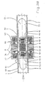
- Fig. 1 shows an exemplary embodiment of a blood pump according to the invention with pump housing 3 and stabilizer housing 2.
- a motor stator 31 is arranged with motor windings 33 around the hollow body 1 around.
- the motor stator 31 drives a conveying part 5, which contains a motor rotor 32 and a rotor hub 52 and which is mounted in the interior of the tubular hollow body 1.
- the rotor hub 52 has a rotor blading 53.
- fluid guide devices 7 and 7 ' are fixed to the inner wall of the tubular hollow body 1 with fluid guide blading 72 and 72'. Between the fluid guide devices, 7 and 7 'and the rotor hub 52, a so-called hub gap 9 is formed.
- the motor stator 31 of the motor rotor 32 which is combined with the rotor hub 52, set in rotation.
- the blood flowing out of the heart is fed through a bend 6 to the delivery part 5, where it is set in rotation by means of the rotor blading 53, wherein the rotor hub 52 ensures flow-dynamic favorable conditions.
- the fluid guide device 7 'with its blading 72' connected upstream to the hollow body 1 ensures its flow.
- the pressure sensor 60 allows the pressure measurement in the inflowing fluid.
- the conveying part 5 gets its drive in a conventional manner by magnetic coupling of the motor rotor 32 with the motor stator 31.
- a formation of thrombi in blood as medium to be conveyed is greatly minimized because due to the magnetic bearing no bearing elements are arranged in the flow, the one Formation of dead water areas could bring about.
- a turbulence and associated flow losses takes place only to a small extent.
- One Rotor gap 8 between the rotor hub 52 and inner wall of the hollow body 1 has a width that keeps the flow losses small and at the same time limits the engine losses that increase with increasing distance of the motor rotor 32 from the motor stator 31. For example, a width of the rotor gap 8 between 0.5 and 2.5 mm has proven particularly favorable.
- the fluid After acceleration of the fluid through the rotor blading 53 of the rotor hub 52 and an associated pressure build-up, the fluid is conducted into the fluid guide 7, where it undergoes a deflection in the axial direction and a further pressure build-up takes place.
- Shaping the fluid-Leitbeschaufelung 72 of the fluid guide 7 ensures that the deflection of the fluid in the axial direction takes place gently and also substantially without turbulence.
- FIG. 2 and FIG. 2 a further show, in longitudinal section and in cross section, a further exemplary embodiment of a blood pump with a magnetically mounted rotor hub 52.
- the motor rotor 32 is combined with permanent magnetic bearing elements 42 arranged at each end, which are held in a version 4.
- permanent magnetic bearing elements 42 opposite permanent magnetic bearing elements 41 are arranged.
- the permanent magnetic bearing elements 41 and 42 are oppositely poled. The axially directed, between the permanent magnetic bearing elements 41 and 42 forming attraction ensures that the conveyor part 5 is held coaxially in the tubular hollow body 1 and radial deflections are corrected.
- Position sensors 43 which are also arranged in the fluid guiding devices 7 and 7 ', determine the width of the hub gap 9 and regulate them via the axial stabilizer 12.
- the axial stabilizer 12 is arranged in a stabilizer housing 2.
- pressure sensors 60 and a flow sensor 61 for characterizing the flow are provided.
- the existing from the motor rotor 32 and the permanent magnetic bearing elements 42 and the rotor blading 53 conveying part 5 is rotated via the motor stator 31 in rotation. Radial deviations in the rotation are intercepted by the oppositely poled permanent-magnetic bearing elements, while the axial stabilization takes place via the position sensors 43 and the axial stabilizers 12.
- the concentration of the main mass of the permanent magnetic bearing elements 42 in the region of the axis of the conveying part 5 allows the pump in a pulsatile mode of operation operate, for example, by rapid speed change of the rotor.
- the permanent magnetic bearing elements 41 and 42 are also formed as a solid cylinder as a permanent magnetic rings also with axial magnetization. Any configurations known to those skilled in the art may be used for the precise formation of the permanent magnetic bearing elements 41 and 42.
- an axial stabilizer 12 which interacts with position sensors 43 and acts on the conveying part 5 via the fluid guide devices 7 and 7 'on the front side and an electronic control circuit not shown here used.
- the axial stabilizer 12 causes an active control of the axial position of the conveyor part 5, wherein the stabilizing coils are acted upon in accordance with the scheme with currents and thereby generate an axial magnetic flux, which overlaps the axial magnetic flux of the permanent magnetic elements and the control of the axial position.
- the position sensors 43 detect deviations from the axial nominal position of the conveying part 5 and forward this information to the control circuit.
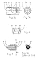
- Fig. 2b and Fig. 2c show in longitudinal and in cross section a further exemplary embodiment of a device according to the invention.
- the brackets 75 which are arranged in front of and behind the conveying part 5 as seen in the flow direction, consist of a hub 73, which are fastened with supports 74 on the inner wall of the tubular hollow body 1.
- the supports 74 are arranged here by way of example at intervals of 90 ° about the hub 73. In principle, a support 74 would be sufficient.
- the holder 75 essentially serves to receive the permanent-magnetic bearing elements 41.
- the axial stabilizer 12, the position sensor 43 and an electronic control unit, not shown, ensure axial stabilization.
- the conveying part 5 and the fluid guide 7 are conical in a further exemplary embodiment.
- a conical rotor 80 of the conveying part 5 increases in the flow direction and continues to conically conical in a conical guide 81 via.
- the permanent magnetic bearing elements 41 and 42 are oppositely poled, the axial stabilization also takes place here via the position sensors 43 in conjunction with the axial stabilizer 12th
- FIGS. 3 a and 3 b show an exemplary embodiment of the holder 75 with supports 74 in longitudinal and cross-sectional detail.
- Fig. 4 shows a conveying part 5 with the rotor hub 52, around which two rotor blades 53 and 53 'are arranged.
- the arrangement of two or more rotor blades 53 makes it possible to increase the effect of the blading of the conveying part 5.
- fluid guiding devices 7 and 7 ' are shown in longitudinal and in cross section, in which the permanent magnetic bearing element 41 is surrounded by the position sensor 43.
- the rib 724 is formed bent.
- convex and / or concave curvatures, radial blading, micro-blades, ribs, grooves and eccentric elevations 725 (FIG. 6c) of any shape or simply roughness of the surface can also be provided on the end face 722.
- these means are means by which the fluid is conveyed radially out of the hub gap 9 (see FIG. 8) during rotation of the delivery part 5.
- these means may also be arranged on the end face of the rotor hub 52.
- the illustration according to FIG. 7 advantageously additionally brings about an improvement in the emergency running properties in the case of the failure of the axial stabilization.
- the hub 73 has an axial bore 726, through which the fluid to be delivered flows, causing the fluid in the hub gap 9 to be transported additionally radially.
- the magnetic bearing according to the invention is not limited to cylindrical shapes of the magnets. Further geometric configurations of the permanent magnetic bearing elements 41 and 42 are possible.
Landscapes
- Engineering & Computer Science (AREA)
- Health & Medical Sciences (AREA)
- Heart & Thoracic Surgery (AREA)
- Mechanical Engineering (AREA)
- Cardiology (AREA)
- General Health & Medical Sciences (AREA)
- Life Sciences & Earth Sciences (AREA)
- Veterinary Medicine (AREA)
- Public Health (AREA)
- Animal Behavior & Ethology (AREA)
- Anesthesiology (AREA)
- Biomedical Technology (AREA)
- Hematology (AREA)
- General Engineering & Computer Science (AREA)
- Power Engineering (AREA)
- Fluid Mechanics (AREA)
- Microelectronics & Electronic Packaging (AREA)
- Physics & Mathematics (AREA)
- Structures Of Non-Positive Displacement Pumps (AREA)
- External Artificial Organs (AREA)
- Measuring Fluid Pressure (AREA)
Applications Claiming Priority (3)
| Application Number | Priority Date | Filing Date | Title |
|---|---|---|---|
| DE19918841 | 1999-04-20 | ||
| EP03090441.1A EP1416163B1 (fr) | 1999-04-20 | 2000-04-19 | Pompe centrifuge avec auto-nettoyage des surfaces de palier |
| EP00927001A EP1208630B1 (fr) | 1999-04-20 | 2000-04-19 | Dispositif pour refouler des substances fluides a une ou a plusieurs phases sans les alterer |
Related Parent Applications (5)
| Application Number | Title | Priority Date | Filing Date |
|---|---|---|---|
| EP00927001.8 Division | 2000-04-19 | ||
| EP03090441.1A Division-Into EP1416163B1 (fr) | 1999-04-20 | 2000-04-19 | Pompe centrifuge avec auto-nettoyage des surfaces de palier |
| EP03090441.1A Division EP1416163B1 (fr) | 1999-04-20 | 2000-04-19 | Pompe centrifuge avec auto-nettoyage des surfaces de palier |
| EP00927001A Division EP1208630B1 (fr) | 1999-04-20 | 2000-04-19 | Dispositif pour refouler des substances fluides a une ou a plusieurs phases sans les alterer |
| EP03090441.1 Division | 2003-12-16 |
Publications (3)
| Publication Number | Publication Date |
|---|---|
| EP1841044A2 true EP1841044A2 (fr) | 2007-10-03 |
| EP1841044A3 EP1841044A3 (fr) | 2011-05-11 |
| EP1841044B1 EP1841044B1 (fr) | 2014-03-12 |
Family
ID=32094806
Family Applications (3)
| Application Number | Title | Priority Date | Filing Date |
|---|---|---|---|
| EP03090441.1A Expired - Lifetime EP1416163B1 (fr) | 1999-04-20 | 2000-04-19 | Pompe centrifuge avec auto-nettoyage des surfaces de palier |
| EP03090442.9A Expired - Lifetime EP1415672B1 (fr) | 1999-04-20 | 2000-04-19 | Pompe avec capteur de pression |
| EP07075547.5A Expired - Lifetime EP1841044B1 (fr) | 1999-04-20 | 2000-04-19 | Pompe centrifuge avec système de drainage du palier |
Family Applications Before (2)
| Application Number | Title | Priority Date | Filing Date |
|---|---|---|---|
| EP03090441.1A Expired - Lifetime EP1416163B1 (fr) | 1999-04-20 | 2000-04-19 | Pompe centrifuge avec auto-nettoyage des surfaces de palier |
| EP03090442.9A Expired - Lifetime EP1415672B1 (fr) | 1999-04-20 | 2000-04-19 | Pompe avec capteur de pression |
Country Status (2)
| Country | Link |
|---|---|
| EP (3) | EP1416163B1 (fr) |
| DE (1) | DE50004809D1 (fr) |
Families Citing this family (1)
| Publication number | Priority date | Publication date | Assignee | Title |
|---|---|---|---|---|
| EP3108809A1 (fr) | 2015-06-22 | 2016-12-28 | Berlin Heart GmbH | Dispositif et procede de mesure de pression dans le c ur d'un patient |
Citations (2)
| Publication number | Priority date | Publication date | Assignee | Title |
|---|---|---|---|---|
| US4398773A (en) * | 1979-05-12 | 1983-08-16 | Kernforschungsanlage Julich Gesellschaft Mit Beschrankter Haftung | Magnetic suspension assembly for a rotor |
| US5211546A (en) * | 1990-05-29 | 1993-05-18 | Nu-Tech Industries, Inc. | Axial flow blood pump with hydrodynamically suspended rotor |
Family Cites Families (4)
| Publication number | Priority date | Publication date | Assignee | Title |
|---|---|---|---|---|
| US5078741A (en) * | 1986-10-12 | 1992-01-07 | Life Extenders Corporation | Magnetically suspended and rotated rotor |
| US6100618A (en) * | 1995-04-03 | 2000-08-08 | Sulzer Electronics Ag | Rotary machine with an electromagnetic rotary drive |
| JP3777490B2 (ja) * | 1997-01-31 | 2006-05-24 | 株式会社荏原製作所 | 送液装置及びその制御方法 |
| US5964694A (en) * | 1997-04-02 | 1999-10-12 | Guidant Corporation | Method and apparatus for cardiac blood flow assistance |
-
2000
- 2000-04-19 EP EP03090441.1A patent/EP1416163B1/fr not_active Expired - Lifetime
- 2000-04-19 DE DE50004809T patent/DE50004809D1/de not_active Expired - Lifetime
- 2000-04-19 EP EP03090442.9A patent/EP1415672B1/fr not_active Expired - Lifetime
- 2000-04-19 EP EP07075547.5A patent/EP1841044B1/fr not_active Expired - Lifetime
Patent Citations (2)
| Publication number | Priority date | Publication date | Assignee | Title |
|---|---|---|---|---|
| US4398773A (en) * | 1979-05-12 | 1983-08-16 | Kernforschungsanlage Julich Gesellschaft Mit Beschrankter Haftung | Magnetic suspension assembly for a rotor |
| US5211546A (en) * | 1990-05-29 | 1993-05-18 | Nu-Tech Industries, Inc. | Axial flow blood pump with hydrodynamically suspended rotor |
Also Published As
| Publication number | Publication date |
|---|---|
| EP1415672A2 (fr) | 2004-05-06 |
| EP1415672B1 (fr) | 2014-09-10 |
| DE50004809D1 (de) | 2004-01-29 |
| EP1416163B1 (fr) | 2014-04-09 |
| EP1416163A2 (fr) | 2004-05-06 |
| EP1415672A3 (fr) | 2005-03-16 |
| EP1841044B1 (fr) | 2014-03-12 |
| EP1841044A3 (fr) | 2011-05-11 |
| EP1416163A3 (fr) | 2004-07-28 |
Similar Documents
| Publication | Publication Date | Title |
|---|---|---|
| EP1208630B1 (fr) | Dispositif pour refouler des substances fluides a une ou a plusieurs phases sans les alterer | |
| EP1360416B1 (fr) | Dispositif de transport axial de liquides | |
| EP0904117B1 (fr) | Pompe a sang intravasculaire | |
| EP2051751B1 (fr) | Pompe à sang | |
| DE10123139B4 (de) | Verfahren zur Regelung einer Unterstützungspumpe für Fluidfördersysteme mit pulsatilem Druck | |
| EP1727988B1 (fr) | Pompe | |
| EP2814534B1 (fr) | Pompe a sang intravasculaire | |
| EP0819330B1 (fr) | Machine rotative avec systeme electromagnetique d'entrainement en rotation | |
| DE60023523T2 (de) | Hydraulische Dichtung für Rotationspumpen | |
| EP0699447B1 (fr) | Pompe à sang centrifuge | |
| EP2319552B1 (fr) | Pompe à sang | |
| WO2000062842A1 (fr) | Dispositif pour le transport axial de milieux fluides | |
| EP1261385B1 (fr) | Pompe a sang | |
| DE102010011998A1 (de) | Fluidpumpeinrichtung | |
| EP2366412A2 (fr) | Dispositif à catheter | |
| DE10108815B4 (de) | Vorrichtung zur axialen Förderung von Körperflüssigkeiten | |
| EP1841044B1 (fr) | Pompe centrifuge avec système de drainage du palier | |
| EP3612245A1 (fr) | Dispositif d'échange de matière | |
| DE102020102473A1 (de) | Pumpe zum Fördern eines Fluids und Verfahren zum Herstellen einer Pumpe | |
| WO1998028543A2 (fr) | Dispositif de refoulement non alterant de fluides mono- ou polyphasiques |
Legal Events
| Date | Code | Title | Description |
|---|---|---|---|
| PUAI | Public reference made under article 153(3) epc to a published international application that has entered the european phase |
Free format text: ORIGINAL CODE: 0009012 |
|
| 17P | Request for examination filed |
Effective date: 20070629 |
|
| AC | Divisional application: reference to earlier application |
Ref document number: 1416163 Country of ref document: EP Kind code of ref document: P Ref document number: 1208630 Country of ref document: EP Kind code of ref document: P |
|
| AK | Designated contracting states |
Kind code of ref document: A2 Designated state(s): AT CH DE FR GB IT LI |
|
| RIC1 | Information provided on ipc code assigned before grant |
Ipc: A61M 1/10 20060101ALI20070906BHEP Ipc: F04D 29/041 20060101AFI20070906BHEP Ipc: F16C 39/06 20060101ALI20070906BHEP |
|
| RTI1 | Title (correction) |
Free format text: CENTRIFUGAL PUMP WITH FLUSHED BEARING GAP |
|
| RIN1 | Information on inventor provided before grant (corrected) |
Inventor name: MUELLER, JOHANNES Inventor name: NUESSER, PETER Inventor name: PETERS, HANS-ERHARD Inventor name: FREMEREY, JOHAN K. |
|
| PUAL | Search report despatched |
Free format text: ORIGINAL CODE: 0009013 |
|
| AK | Designated contracting states |
Kind code of ref document: A3 Designated state(s): AT CH DE FR GB IT LI |
|
| AKX | Designation fees paid |
Designated state(s): AT CH DE FR GB IT LI |
|
| GRAP | Despatch of communication of intention to grant a patent |
Free format text: ORIGINAL CODE: EPIDOSNIGR1 |
|
| INTG | Intention to grant announced |
Effective date: 20130910 |
|
| GRAS | Grant fee paid |
Free format text: ORIGINAL CODE: EPIDOSNIGR3 |
|
| GRAA | (expected) grant |
Free format text: ORIGINAL CODE: 0009210 |
|
| AC | Divisional application: reference to earlier application |
Ref document number: 1416163 Country of ref document: EP Kind code of ref document: P Ref document number: 1208630 Country of ref document: EP Kind code of ref document: P |
|
| AK | Designated contracting states |
Kind code of ref document: B1 Designated state(s): AT CH DE FR GB IT LI |
|
| REG | Reference to a national code |
Ref country code: GB Ref legal event code: FG4D Free format text: NOT ENGLISH |
|
| REG | Reference to a national code |
Ref country code: CH Ref legal event code: EP |
|
| REG | Reference to a national code |
Ref country code: AT Ref legal event code: REF Ref document number: 656482 Country of ref document: AT Kind code of ref document: T Effective date: 20140315 |
|
| REG | Reference to a national code |
Ref country code: DE Ref legal event code: R096 Ref document number: 50016361 Country of ref document: DE Effective date: 20140424 |
|
| REG | Reference to a national code |
Ref country code: CH Ref legal event code: PL |
|
| REG | Reference to a national code |
Ref country code: DE Ref legal event code: R097 Ref document number: 50016361 Country of ref document: DE |
|
| PLBE | No opposition filed within time limit |
Free format text: ORIGINAL CODE: 0009261 |
|
| STAA | Information on the status of an ep patent application or granted ep patent |
Free format text: STATUS: NO OPPOSITION FILED WITHIN TIME LIMIT |
|
| PG25 | Lapsed in a contracting state [announced via postgrant information from national office to epo] |
Ref country code: LI Free format text: LAPSE BECAUSE OF NON-PAYMENT OF DUE FEES Effective date: 20140430 Ref country code: CH Free format text: LAPSE BECAUSE OF NON-PAYMENT OF DUE FEES Effective date: 20140430 |
|
| 26N | No opposition filed |
Effective date: 20141215 |
|
| REG | Reference to a national code |
Ref country code: DE Ref legal event code: R097 Ref document number: 50016361 Country of ref document: DE Effective date: 20141215 |
|
| PG25 | Lapsed in a contracting state [announced via postgrant information from national office to epo] |
Ref country code: IT Free format text: LAPSE BECAUSE OF FAILURE TO SUBMIT A TRANSLATION OF THE DESCRIPTION OR TO PAY THE FEE WITHIN THE PRESCRIBED TIME-LIMIT Effective date: 20140312 |
|
| REG | Reference to a national code |
Ref country code: AT Ref legal event code: MM01 Ref document number: 656482 Country of ref document: AT Kind code of ref document: T Effective date: 20140419 |
|
| PG25 | Lapsed in a contracting state [announced via postgrant information from national office to epo] |
Ref country code: AT Free format text: LAPSE BECAUSE OF NON-PAYMENT OF DUE FEES Effective date: 20140419 |
|
| REG | Reference to a national code |
Ref country code: DE Ref legal event code: R082 Ref document number: 50016361 Country of ref document: DE Representative=s name: PFENNING, MEINIG & PARTNER MBB PATENTANWAELTE, DE |
|
| REG | Reference to a national code |
Ref country code: FR Ref legal event code: PLFP Year of fee payment: 17 |
|
| PGFP | Annual fee paid to national office [announced via postgrant information from national office to epo] |
Ref country code: GB Payment date: 20160421 Year of fee payment: 17 |
|
| PGFP | Annual fee paid to national office [announced via postgrant information from national office to epo] |
Ref country code: FR Payment date: 20160421 Year of fee payment: 17 |
|
| GBPC | Gb: european patent ceased through non-payment of renewal fee |
Effective date: 20170419 |
|
| REG | Reference to a national code |
Ref country code: FR Ref legal event code: ST Effective date: 20171229 |
|
| PG25 | Lapsed in a contracting state [announced via postgrant information from national office to epo] |
Ref country code: FR Free format text: LAPSE BECAUSE OF NON-PAYMENT OF DUE FEES Effective date: 20170502 |
|
| PG25 | Lapsed in a contracting state [announced via postgrant information from national office to epo] |
Ref country code: GB Free format text: LAPSE BECAUSE OF NON-PAYMENT OF DUE FEES Effective date: 20170419 |
|
| PGFP | Annual fee paid to national office [announced via postgrant information from national office to epo] |
Ref country code: DE Payment date: 20190430 Year of fee payment: 20 |
|
| REG | Reference to a national code |
Ref country code: DE Ref legal event code: R071 Ref document number: 50016361 Country of ref document: DE |