EP1841018A2 - Verbesserungen an und im Zusammenhang mit elektrischen Hochfrequenzsteckverbindern - Google Patents
Verbesserungen an und im Zusammenhang mit elektrischen Hochfrequenzsteckverbindern Download PDFInfo
- Publication number
- EP1841018A2 EP1841018A2 EP07251457A EP07251457A EP1841018A2 EP 1841018 A2 EP1841018 A2 EP 1841018A2 EP 07251457 A EP07251457 A EP 07251457A EP 07251457 A EP07251457 A EP 07251457A EP 1841018 A2 EP1841018 A2 EP 1841018A2
- Authority
- EP
- European Patent Office
- Prior art keywords
- contacts
- high frequency
- electrical connector
- frequency electrical
- contact
- Prior art date
- Legal status (The legal status is an assumption and is not a legal conclusion. Google has not performed a legal analysis and makes no representation as to the accuracy of the status listed.)
- Granted
Links
Images


Classifications
-
- H—ELECTRICITY
- H01—ELECTRIC ELEMENTS
- H01R—ELECTRICALLY-CONDUCTIVE CONNECTIONS; STRUCTURAL ASSOCIATIONS OF A PLURALITY OF MUTUALLY-INSULATED ELECTRICAL CONNECTING ELEMENTS; COUPLING DEVICES; CURRENT COLLECTORS
- H01R24/00—Two-part coupling devices, or either of their cooperating parts, characterised by their overall structure
- H01R24/60—Contacts spaced along planar side wall transverse to longitudinal axis of engagement
- H01R24/62—Sliding engagements with one side only, e.g. modular jack coupling devices
- H01R24/64—Sliding engagements with one side only, e.g. modular jack coupling devices for high frequency, e.g. RJ 45
-
- H—ELECTRICITY
- H01—ELECTRIC ELEMENTS
- H01R—ELECTRICALLY-CONDUCTIVE CONNECTIONS; STRUCTURAL ASSOCIATIONS OF A PLURALITY OF MUTUALLY-INSULATED ELECTRICAL CONNECTING ELEMENTS; COUPLING DEVICES; CURRENT COLLECTORS
- H01R13/00—Details of coupling devices of the kinds covered by groups H01R12/70 or H01R24/00 - H01R33/00
- H01R13/646—Details of coupling devices of the kinds covered by groups H01R12/70 or H01R24/00 - H01R33/00 specially adapted for high-frequency, e.g. structures providing an impedance match or phase match
- H01R13/6461—Means for preventing cross-talk
- H01R13/6467—Means for preventing cross-talk by cross-over of signal conductors
Definitions
- the present invention relates to high frequency electrical connectors, and particularly to electrical contacts provided in electrical sockets for such connectors.
- Multiple pole connectors are used in applications such as data communications networks and telecommunications networks. To enable such networks to transmit increased volume of data, it is necessary to increase the operating frequency, and hence the data transfer rate. To ensure compatibility with existing lower operating frequency networks, it is desirable to provide data communications connectors that can operate at high data rates while still remaining backward compatible with older, lower data rate systems.
- Data transfer rates are limited by a degradation of the signal and / or signal to noise ratio that occurs during transmission.
- a factor that may cause such degradation is crosstalk between adjacent pairs of conductors, where a data signal on one pair of conductors induces an electrical signal noise on an adjacent conductor.
- such a known data communications connector is the RJ45 connector which is provided with eight spring contacts, arranged so that all of the spring contacts run parallel and in line for a substantial proportion of their lengths.
- This configuration has been sufficient for systems characterised up to 100MHz (Cat 5/5e), provided contact lengths are minimised.
- Cat 6 i.e. Cat 6 / 250MHz and higher to Augmented Cat 6 at 500MHz
- crosstalk compensation circuitry is applied relatively late and becomes ineffective at high frequencies.
- a high frequency electrical connector comprising a socket and a plug, the plug insertable into the socket in a first direction, the socket and plug each having multiple electrical contacts which are arranged to electrically interconnect the plug and socket, the socket having a base for fixedly mounting a fixed end of the socket contacts, the socket contacts having contact areas arranged for electrically interconnecting to corresponding plug contacts, the contact areas being aligned so as to be parallel in a first dimension with the first direction, and having a resiling portion in-between the contact areas and the fixed ends, the socket contacts are formed in several different shapes, wherein each shape has an at least partly arcuate contact area and wherein a free end of each contact is enclosed by the base.
- a benefit of the invention is that a high frequency data communications connector for use with a standard RJ45 plug may be arranged to have short contacts where the contact ends are protected from physical damage during both the manufacturing process and during use when a plug is inserted and removed from the socket.
- the base comprises at least an upper part and a lower part, each contact being arranged to mount between the upper part and lower part.
- a benefit of each contact being arranged to mount between the upper part and lower part is that the small contacts may be assembled into a sub-assembly.
- the upper and lower part clip together to retain the contacts Preferably the upper and lower part clip together to retain the contacts.
- a benefit of the upper and lower part clip together to retain the contacts is that the sub-assembly may be safely handled, and passed, for example, through a flow soldering process without risk that the contacts will be dislodged.
- the free ends are enclosed under a portion of the upper part, and more preferably the fixed ends pass through the lower part.
- a benefit of the free ends being enclosed under the upper part, and the fixed ends passing through the lower part is that the base may be moulded from a plastics material using simple tooling.
- a further benefit is that the free end of each of the contacts are protected during subsequent assembly operations and during the use of the socket when in service.
- a further benefit of the contacts at the fixed ends passing through the lower part is that the fixed ends are accurately and repeatably positioned ready for insertion into a circuit board for subsequently soldering.
- At least one contact has a free end facing substantially in the first direction, and at least a second contact has a free end facing substantially in a direction opposite to the first direction.
- a benefit of at least one contact has a free end facing substantially in the first direction, and at least a second contact has a free end facing substantially in a direction opposite to the first direction is that the negative effect on crosstalk introduced by the contacts of pin-pairs 3,6 & 4,5 is reduced by effectively spacing the contacts apart, while maintaining small overall dimensions.
- all the arcuate contact areas are tangential to a contact plane passing through a point of contact between the contacts and the plug contacts when a plug is fully inserted into the socket.
- a benefit of all the arcuate contact areas are tangential to a contact plane passing through a point of contact between the contacts and the plug contacts when a plug is fully inserted into the socket.
- a length of a shortest contact, measured in the first direction is equal to or less than two thirds of an overall length measured across all the contacts, the overall length measured in the same first direction.
- a benefit of a length of a shortest contact, measured in the first direction is equal to or less than two thirds of an overall length measured across all the contacts
- a minimum bend radius of the resiling portion is greater than 0.5mm.
- a benefit of a minimum bend radius of the resiling portion is greater than 0.5mm is that the use of a larger radius avoids creating a noise radiating "hot-spot".
- a plurality of the contacts have a substantially straight portion adjacent the fixed end, the substantially straight portion having a longitudinal axis parallel to the first direction.
- a benefit of a plurality of the contacts have a substantially straight portion adjacent the fixed end, the substantially straight portion having a longitudinal axis parallel to the first direction.
- the substantially straight portion has a wider portion, the wider portion being arranged to wedge in slots in the base.
- a benefit of the substantially straight portion has a wider portion, the wider portion being arranged to wedge in slots in the base is that the contacts are held in place during the sub-assembly of the base.
- the wider portion has a chamfered side facing in a direction of insertion of the contact into the lower part of the base, and a substantially flat side facing the opposite direction.
- a benefit of the wider portion has a chamfered side facing in a direction of insertion of the contact into the lower part of the base, and a substantially flat side facing the opposite direction is that the contacts may be more easily inserted into the base, and then held more firmly in position.
- the substantially straight portions of at least two contacts are arranged on a plane parallel to the contact plane, and wherein at least the straight portion of a further contact being arranged on a different plane parallel to the contact plane.
- a benefit of the substantially straight portions of at least two contacts are arranged on a plane parallel to the contact plane, and wherein at least the straight portion of a further contact being arranged on a different plane parallel to the contact plane is that adjacent contacts may be spaced further apart than would be possible in one plane.
- each contact further comprises a perpendicular straight portion in a plane substantially perpendicular to the first direction.
- a benefit of each contact further comprises a perpendicular straight portion in a plane substantially perpendicular to the first direction is that the end of the contacts are all aligned in the same direction.
- the perpendicular straight portions each have chamfered ends at an end of the fixed end for easy insertion into the base and through the holes in the circuit board.
- a benefit of the perpendicular straight portions each have chamfered ends at an end of the fixed end for easy insertion into the base and through the holes in the circuit board is that the aligned pins may be inserted into closely sized holes in a printed circuit board.
- the perpendicular straight portions are arranged to pass through the base to the circuit board in four different perpendicular planes, each plane being perpendicular to the first direction.
- a benefit of the perpendicular straight portions are arranged to pass through the base to the circuit board in four different perpendicular planes, each plane being perpendicular to the first direction is that adjacent contacts may be spaced further apart than would be possible in one plane and further that the track layout on the printed circuit board may be improved.
- the contacts are arranged so that the perpendicular straight portions of at least three contacts lie on each of two of the perpendicular planes.
- a benefit of the contacts are arranged so that the perpendicular straight portions of at least three contacts lie on each of two of the perpendicular planes is that the contacts that are most susceptible to crosstalk may be kept furthest away from each other.
- each free end comprises a substantially straight portion, arranged at an angle to a tangent extending from an end of the arcuate contact areas.
- a benefit of each free end comprises a substantially straight portion, arranged at an angle to a tangent extending from an end of the arcuate contact areas is that the free end may be more securely maintained enclosed in the base, and will resist being disengaged from being enclosed on a roughly inserted plug.
- said angle is greater than 15 degrees and less than 25 degrees.
- a benefit of said angle is greater than 15 degrees and less than 25 degrees is that the end may be positioned furthest away from adjacent resiling portions of adjacent contacts.
- the free ends of at least one of the contacts is at least one fifth of the said overall length measured in the same first direction from an end across which the overall length is measured. More preferably the free ends of each of the contacts is at least one fifth of the said overall length measured in the same first direction from an end across which the overall length is measured.
- a benefit of the free ends of each of the contacts being at least one fifth of the said overall length measured in the same first direction from an end across which the overall length is measured, is that the ends may be positioned further away from adjacent resiling portions of adjacent contacts.
- the base and the circuit board are arranged so that there is a gap between the circuit board and the base.
- the gap is at least 0.1mm, and more preferably it is 0.3mm.
- a benefit of a gap between the circuit board and the base is that any pressure applied to the base in normal use does not result in a change in the performance of the connector, due to effects such as capacitance.
- a high frequency electrical connector 1 comprising a socket 2 and a plug 3.
- the plug 3 is insertable into the socket 2 in a first direction 1D.
- the socket 2 and plug 3 each have multiple electrical contacts 21 to 28 and 31 to 38 (only one plug contact being visible in Figure 1) respectively, which are arranged to electrically interconnect the plug and socket.
- the socket 2 has a base 4 for fixedly mounting a fixed end 41 to 48 of each of the socket contacts 21 to 28 respectively.
- the base is mounted inside a housing 29, that provides location and support for the circuit board 30 and the base 4.
- the housing 29 is arranged to receive the plug, so as to guide and support it in such a position so that electrical contact is made between the socket contacts and the corresponding plug contacts.
- the socket contacts 21 to 28 have contact areas 51 to 58 arranged for electrically interconnecting to corresponding plug contacts 31 to 38 respectively.
- the contact areas being aligned so as to be parallel in a first dimension 1M with the first direction 1D.
- Each contact has a resiling portion 61 to 68 in-between the contact areas 51 to 58 respectively and the fixed ends 41 to 48 respectively.
- the socket contacts 21 to 28 are formed in a plurality of shapes, and from Figure 4 it can be seen that in this embodiment there are four different shapes 1S, 2S, 3S, 4S, each shape having an at least partly arcuate contact areas 81 to 88.
- the at least partly arcuate contact areas 81 to 88 are between the resiling portion and a free end 71 to 78 of each contact.
- the free end of each contact is enclosed by the base 4.
- the socket may be arranged to have short contacts where the contact ends are protected from physical damage during both the manufacturing process and during use when a plug is inserted and removed from the socket.
- Shape 1S has a length 4J
- shape 2S has a length 4K
- shape 3S has a length 4L
- shape 4S has a length 4M, all measured along the direction 1D.
- Shapes 1S and 3S being longer than shapes 2S and 4S.
- the plug 3 is preferably a standard RJ45 plug, which in Figure 1 is shown to be at a maximum size permitted by the relevant standard. Hence the contacts in Figure 1 are shown resiliently deflected to their maximum amount 1V.
- Figure 1A shows the contacts resiliently deflected a minimum acceptable amount 1U to achieve satisfactory performance of the high frequency electrical connector 1'.
- Figure 1A shows some detail resiliently deflected a minimum acceptable amount 1U to achieve satisfactory performance of the high frequency electrical connector 1'.
- Figure 1A such as a housing, but the connector 1' is similar or identical to that of Figure 1.
- the base 4 can be seen to comprise an upper part 401 and a lower part 402, each contact being arranged to mount between the upper part and lower part.
- the upper part is provided with guides 403 and 404 to provide an accurate means of locating the base in the socket housing 29.
- the contacts When the contacts are mounted between the upper part and lower part they form an easily handled sub-assembly.
- the upper and lower parts clip together with resilient clips 421 and 422, which have latching faces 423 and 424, which in use abut against abutments 425 and 426 in the lower part of the base to retain the contacts.
- lower part 402 of the base 4 can be seen to comprise location pins 427 and 428 for ensuring accurate orientation with the upper part 401 when they are clipped together.
- the lower part 402 also has horizontal locations 461 to 468 for providing support to straight portion 91 to 98 of the socket contacts 21 to 28.
- each horizontal location At an end of each horizontal location is a rectangular hole 471 to 478 through the lower part to accept the perpendicular straight portions 121 to 128.
- Horizontal locations 462 and 467 are on a raised plane above the other locations, so that the contacts 22 and 27 respectively are spaced apart from the contacts that are adjacent to them.
- the lower part 402 is provided with four spacers 411 to 414, one at each corner. On two diagonal corners, location pillars 415 and 416 are provided to locate in corresponding holes in the circuit boards.
- the spacers and pillars standing off the base from the circuit board are important to avoid change in performance due to plug tolerances or movement of the twisted pair cable applying a force to the plug, and hence to the socket. Having the pillars standing off the base from the circuit board enables the use of a double sided circuit board with most of the tracks for the socket contacts being mounted on the side of the board adjacent to the base. Hence a distance between the contacts and the tracks on the circuit board is minimised.
- the air gap between the circuit board and the base provided by the spacers also prevents wicking of the solder up the fixed ends into the base during the soldering process.
- a suitable size for the air gap between the circuit board and the base has been found to be a minimum of 0.1mm. Preferably the gap is 0.5mm.
- each part of the base may be moulded from a plastics material with a simple mould tool with no moving cores.
- the free end of each contact is enclosed under a portion 449 of the upper part, the free end of each of the contacts are protected during subsequent assembly operations and during the use of the socket when in service a plug is inserted in to the socket or removed from the socket. For example, if a plug were to snag or catch on an unenclosed end of a contact, it would damage such a contact so that it would become unusable.
- the contacts 21, 22, 23 and 25 have a free end facing substantially in the first direction 1D
- the contacts 24, 26, 27 and 28 have a free end facing substantially in a direction 1R opposite to the first direction.
- the arcuate contact areas 81 to 88 are tangential to a contact plane 1P passing through a point of contact between the contacts and the plug contacts when a plug is fully inserted into the socket. Having arcuate contact areas that are tangential to a contact plane passing through a point of contact between the contacts and the plug contacts when a plug is fully inserted into the socket, reduces a variability in the positions taken-up by the contacts when in use with different plugs. Hence, an effect of compensation for crosstalk applied by the tracks on the circuit board 30 on the performance of the connector is more predictable and a closer tolerance on performance can be achieved than would otherwise be possible.
- a length 4K and 4M of a short contact, measured in the first direction is equal to or less than two thirds of an overall length 4H measured across all the contacts, the overall length measured in the same first direction 1D.
- Contact shape 2S has a minimum bend radius 4R of the resiling portion 62 which is greater than 0.5mm. An effect of a small radius is to provide a hot spot for radiation of electrical noise, which would be detrimental to the performance of the connector.
- the contacts each have a substantially straight portion 91 to 98 adjacent the fixed end 41 to 48, the substantially straight portion having a longitudinal axis parallel to the first direction 1D.
- the straight portions provide good location within the base for the contacts.
- the substantially straight portions 91 to 98 each has a wider portion 101 to 108. A width of the wider portion being arranged to wedge in slots 451 to 458 in the base. Hence the contacts are held in place during the sub-assembly of the base.
- the substantially straight portions of at least two contacts 22 and 27 are arranged on a high plane 4T parallel to the contact plane 1P, and the straight portion of contacts 21, 23, 24, 25, 26, and 28 being arranged on a low plane 4U parallel to the contact plane.
- the fixed end 41 to 48 of each socket contact is perpendicular to the adjacent straight portion 91 to 98 and in a plane substantially perpendicular to the first direction.
- the perpendicular straight portions 121 to 128 each have chamfered ends 111 to 118 at an end of the fixed end for easy insertion into the base and through the holes in the base and the circuit board 30, which may be of a closely fitting size, and hence this assists in ensuring close control on the position of the assembled socket contacts.
- the perpendicular straight portions 121 to 128 are arranged to pass through base to circuit board in four different perpendicular planes, each plane being perpendicular to the first direction 1D.
- the perpendicular straight portions are arranged to pass through base to circuit board in four different perpendicular planes, so that adjacent contacts may be spaced further apart than would be possible in one plane and further that the track layout on the printed circuit board may be improved, giving further improvement to the performance of the socket. That is, the contacts that are most susceptible to crosstalk may be kept furthest away from each other.
- Each free end 71 to 78 has a substantially straight portion, arranged at an angle 4N to a tangent extending from an end of the arcuate contact areas 81 to 88.
- the straight free end may be more securely maintained enclosed in the base in enclosures 441 to 448, and will resist being disengaged from the base if a roughly inserted plug exerts an unusual force on the socket contacts.
- the angle 4N is preferably greater than 15 degrees and less than 25 degrees. Such an angle assists in keeping the overall length of the contacts short, and hence the free ends may be positioned further away from adjacent resiling portions of adjacent contacts where these face in the opposite direction.
- each of the socket contacts both the contacts having a free end facing substantially in the first direction, and the contacts having a free end facing substantially in the direction opposite to the first direction have a point of inflection (or point of inflexion) between the arcuate contact areas 81 to 88 and the straight free ends 71 to 78 respectively.
- the point of inflection is between the contact area and the free end of the contact.
- the free ends are a distance of 4P and 4Q from adjacent contacts resiling bend areas.
- the distances 4P and 4Q are preferably at least one fifth of the overall length 4H.
- each of the contacts is spaced at least one fifth of the said overall length measured in the same first direction from an end across which the overall length is measured.
- socket contacts have been orientated in the following position to achieve the required performance.
- Coupling between contacts 23 & 25, and 23 & 21 is strongly desired so these contacts have the same profile to provide maximum coupling.
- Coupling between contacts 26 & 24 and 26 & 28 is also strongly desired so again these contacts have the same profile.
- No coupling between contacts 22 and 23 is desired so contacts 22 is shortened to be out of line and equally contact 26 and 27 are desired not to couple so contact 27 is shortened to be out of line.
- Coupling between contacts 24 and 25 is not desired so contact 24 has been placed in a reverse direction to reduce the coupling.
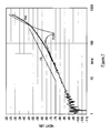
- Figure 7 is a graph showing experimental results obtained when testing an embodiment of the invention, where the straight line 7S represents the standards requirements, and the line 7C6- demonstrates the Cat 6 performance achievable using quality components.
- the results of testing a high speed connector according to present invention are shown on line 7W. The improvement achieved is significant.
- FIG. 6 is an exploded perspective view of a second embodiment of the invention of a high frequency electrical connector 200, comprising a socket 202 and a plug 203 to which are connected twisted pair cables 212 and 213 respectively.
- the plug is an industry standard RJ45 plug, and may be shielded, or unshielded.
- the plug is insertable into the socket in a first direction of arrow 6D.
- the socket 202 has a contact array 220 comprising multiple electrical contacts 221 to 228 mounted to a base 230. All free ends of the contacts 223 and 244 (only two labelled) are enclosed by the base 230.
- the base is provided with four spacers 231 and 232 (others not visible in Figure 6), and the array is mounted to a circuit board 240.
- the spacers space the base away from the circuit board so as to provide an air gap.
- Conductive tracks are provided on a top side 241 of the circuit board 240 to interconnect each of the electrical contacts 221 to 228 with holes 242 (only one labelled) to which insulation displacement connectors 250 and 251 are mounted and electrically connected.
- Wires 214 (only one labelled) of the cable 212 are untwisted sufficiently to attach them to the insulation displacement connectors to effect the electrical connection to the socket.
- Socket 202 has a housing 260 with an aperture 262 defining an entrance to a space to receive the plug 203.
- the array and the insulation displacement connectors When the array and the insulation displacement connectors are mounted to the circuit board, it is assembled to the socket housing by sliding it in the direction of arrow 6A, when slides 229 either side of the base 230 engage with channels 263 in the housing to ensure accurate positioning of the contacts with respect to the aperture 262 to ensure correct mating of the plug and socket contacts.
- a closure plate 263 is provided to close the rear of the housing when the circuit board is in position.
- Fastener 264 is provided to retain the circuit board to the housing 260 by insertion of the fastener 264 through hole 265.
Landscapes
- Coupling Device And Connection With Printed Circuit (AREA)
- Details Of Connecting Devices For Male And Female Coupling (AREA)
Applications Claiming Priority (1)
| Application Number | Priority Date | Filing Date | Title |
|---|---|---|---|
| GB0606791A GB2436646B (en) | 2006-04-01 | 2006-04-01 | Improvements in and relating to high frequency electrical connectors |
Publications (3)
| Publication Number | Publication Date |
|---|---|
| EP1841018A2 true EP1841018A2 (de) | 2007-10-03 |
| EP1841018A3 EP1841018A3 (de) | 2009-12-02 |
| EP1841018B1 EP1841018B1 (de) | 2013-06-12 |
Family
ID=36425244
Family Applications (1)
| Application Number | Title | Priority Date | Filing Date |
|---|---|---|---|
| EP20070251457 Not-in-force EP1841018B1 (de) | 2006-04-01 | 2007-04-02 | Verbesserungen an und im Zusammenhang mit elektrischen Hochfrequenzsteckverbindern |
Country Status (2)
| Country | Link |
|---|---|
| EP (1) | EP1841018B1 (de) |
| GB (1) | GB2436646B (de) |
Citations (2)
| Publication number | Priority date | Publication date | Assignee | Title |
|---|---|---|---|---|
| US20020132532A1 (en) | 2001-03-16 | 2002-09-19 | Henneberger Roy L. | Telecommuications connector with spring assembly and method for assembling |
| GB2393858A (en) | 2002-10-03 | 2004-04-07 | Brand Rex Ltd | High-frequency socket connector |
Family Cites Families (2)
| Publication number | Priority date | Publication date | Assignee | Title |
|---|---|---|---|---|
| US6368144B2 (en) * | 1998-03-23 | 2002-04-09 | The Siemon Company | Enhanced performance modular outlet |
| US6964587B2 (en) * | 2002-11-10 | 2005-11-15 | Bel Fuse Ltd. | High performance, high capacitance gain, jack connector for data transmission or the like |
-
2006
- 2006-04-01 GB GB0606791A patent/GB2436646B/en not_active Expired - Lifetime
-
2007
- 2007-04-02 EP EP20070251457 patent/EP1841018B1/de not_active Not-in-force
Patent Citations (2)
| Publication number | Priority date | Publication date | Assignee | Title |
|---|---|---|---|---|
| US20020132532A1 (en) | 2001-03-16 | 2002-09-19 | Henneberger Roy L. | Telecommuications connector with spring assembly and method for assembling |
| GB2393858A (en) | 2002-10-03 | 2004-04-07 | Brand Rex Ltd | High-frequency socket connector |
Also Published As
| Publication number | Publication date |
|---|---|
| GB2436646B (en) | 2008-08-13 |
| GB2436646A (en) | 2007-10-03 |
| HK1106073A1 (zh) | 2008-02-29 |
| EP1841018B1 (de) | 2013-06-12 |
| GB0606791D0 (en) | 2006-05-10 |
| EP1841018A3 (de) | 2009-12-02 |
Similar Documents
| Publication | Publication Date | Title |
|---|---|---|
| US12362505B2 (en) | I/O connector configured for cable connection to a midboard | |
| US12184012B2 (en) | High speed, high density electrical connector with shielded signal paths preliminary class | |
| CN212085282U (zh) | 端子总成以及电连接器 | |
| CN108736194B (zh) | 小间距高速正交连接器 | |
| CN104871372B (zh) | 缆线到板连接器 | |
| CN203288874U (zh) | 电连接器组件和系统 | |
| US7121898B2 (en) | Shielding configuration for a multi-port jack assembly | |
| US8152568B2 (en) | Cable assembly with new interface | |
| US20210399449A1 (en) | High-density edge connector | |
| TW202135385A (zh) | 高速連接器 | |
| US12300937B2 (en) | High speed electrical connector | |
| US20130215563A1 (en) | Communication modules having connectors on a leading end and systems including the same | |
| US20160006182A1 (en) | Electrical Connector with Ground Bus | |
| CN110419148A (zh) | 用于通信系统的电路卡组件 | |
| US20100081340A1 (en) | Electrical connectors with vertically oriented contacts | |
| US10153592B2 (en) | Communications connectors | |
| US20230378695A1 (en) | High speed electrical connector with high manufacturing tolerance | |
| US7863776B2 (en) | Transceiver connector with integrated magnetics | |
| CN2562409Y (zh) | 电连接器 | |
| EP1841018B1 (de) | Verbesserungen an und im Zusammenhang mit elektrischen Hochfrequenzsteckverbindern | |
| US20030077941A1 (en) | Modular jack assembly with signal conditioning | |
| CN111129808B (zh) | 接地端子组件、电连接器及电连接器组件 | |
| CN104717861A (zh) | 电缆背板系统 | |
| CN111129873B (zh) | 接地端子组件、端子模组及电连接器 | |
| CN1599967A (zh) | 可调节信号的组合插孔组件 |
Legal Events
| Date | Code | Title | Description |
|---|---|---|---|
| PUAI | Public reference made under article 153(3) epc to a published international application that has entered the european phase |
Free format text: ORIGINAL CODE: 0009012 |
|
| 17P | Request for examination filed |
Effective date: 20070426 |
|
| AK | Designated contracting states |
Kind code of ref document: A2 Designated state(s): AT BE BG CH CY CZ DE DK EE ES FI FR GB GR HU IE IS IT LI LT LU LV MC MT NL PL PT RO SE SI SK TR |
|
| AX | Request for extension of the european patent |
Extension state: AL BA HR MK YU |
|
| RIN1 | Information on inventor provided before grant (corrected) |
Inventor name: BRODIE, DOUGLAS STUART Inventor name: JACKSON, DAVID ANDERSON |
|
| PUAL | Search report despatched |
Free format text: ORIGINAL CODE: 0009013 |
|
| AK | Designated contracting states |
Kind code of ref document: A3 Designated state(s): AT BE BG CH CY CZ DE DK EE ES FI FR GB GR HU IE IS IT LI LT LU LV MC MT NL PL PT RO SE SI SK TR |
|
| AX | Request for extension of the european patent |
Extension state: AL BA HR MK RS |
|
| 17Q | First examination report despatched |
Effective date: 20100625 |
|
| AKX | Designation fees paid |
Designated state(s): AT BE BG CH CY CZ DE DK EE ES FI FR GB GR HU IE IS IT LI LT LU LV MC MT NL PL PT RO SE SI SK TR |
|
| GRAC | Information related to communication of intention to grant a patent modified |
Free format text: ORIGINAL CODE: EPIDOSCIGR1 |
|
| GRAP | Despatch of communication of intention to grant a patent |
Free format text: ORIGINAL CODE: EPIDOSNIGR1 |
|
| GRAS | Grant fee paid |
Free format text: ORIGINAL CODE: EPIDOSNIGR3 |
|
| RIN1 | Information on inventor provided before grant (corrected) |
Inventor name: BRODIE, DOUGLAS STUART Inventor name: JACKSON, DAVID ANDERSON |
|
| GRAA | (expected) grant |
Free format text: ORIGINAL CODE: 0009210 |
|
| AK | Designated contracting states |
Kind code of ref document: B1 Designated state(s): AT BE BG CH CY CZ DE DK EE ES FI FR GB GR HU IE IS IT LI LT LU LV MC MT NL PL PT RO SE SI SK TR |
|
| REG | Reference to a national code |
Ref country code: GB Ref legal event code: FG4D |
|
| REG | Reference to a national code |
Ref country code: CH Ref legal event code: EP |
|
| REG | Reference to a national code |
Ref country code: AT Ref legal event code: REF Ref document number: 616987 Country of ref document: AT Kind code of ref document: T Effective date: 20130615 |
|
| REG | Reference to a national code |
Ref country code: IE Ref legal event code: FG4D |
|
| REG | Reference to a national code |
Ref country code: DE Ref legal event code: R096 Ref document number: 602007030991 Country of ref document: DE Effective date: 20130808 |
|
| PG25 | Lapsed in a contracting state [announced via postgrant information from national office to epo] |
Ref country code: FI Free format text: LAPSE BECAUSE OF FAILURE TO SUBMIT A TRANSLATION OF THE DESCRIPTION OR TO PAY THE FEE WITHIN THE PRESCRIBED TIME-LIMIT Effective date: 20130612 Ref country code: SI Free format text: LAPSE BECAUSE OF FAILURE TO SUBMIT A TRANSLATION OF THE DESCRIPTION OR TO PAY THE FEE WITHIN THE PRESCRIBED TIME-LIMIT Effective date: 20130612 Ref country code: SE Free format text: LAPSE BECAUSE OF FAILURE TO SUBMIT A TRANSLATION OF THE DESCRIPTION OR TO PAY THE FEE WITHIN THE PRESCRIBED TIME-LIMIT Effective date: 20130612 Ref country code: ES Free format text: LAPSE BECAUSE OF FAILURE TO SUBMIT A TRANSLATION OF THE DESCRIPTION OR TO PAY THE FEE WITHIN THE PRESCRIBED TIME-LIMIT Effective date: 20130923 Ref country code: LT Free format text: LAPSE BECAUSE OF FAILURE TO SUBMIT A TRANSLATION OF THE DESCRIPTION OR TO PAY THE FEE WITHIN THE PRESCRIBED TIME-LIMIT Effective date: 20130612 Ref country code: GR Free format text: LAPSE BECAUSE OF FAILURE TO SUBMIT A TRANSLATION OF THE DESCRIPTION OR TO PAY THE FEE WITHIN THE PRESCRIBED TIME-LIMIT Effective date: 20130913 |
|
| REG | Reference to a national code |
Ref country code: AT Ref legal event code: MK05 Ref document number: 616987 Country of ref document: AT Kind code of ref document: T Effective date: 20130612 |
|
| REG | Reference to a national code |
Ref country code: NL Ref legal event code: VDEP Effective date: 20130612 |
|
| REG | Reference to a national code |
Ref country code: LT Ref legal event code: MG4D |
|
| PG25 | Lapsed in a contracting state [announced via postgrant information from national office to epo] |
Ref country code: BG Free format text: LAPSE BECAUSE OF FAILURE TO SUBMIT A TRANSLATION OF THE DESCRIPTION OR TO PAY THE FEE WITHIN THE PRESCRIBED TIME-LIMIT Effective date: 20130912 |
|
| PG25 | Lapsed in a contracting state [announced via postgrant information from national office to epo] |
Ref country code: LV Free format text: LAPSE BECAUSE OF FAILURE TO SUBMIT A TRANSLATION OF THE DESCRIPTION OR TO PAY THE FEE WITHIN THE PRESCRIBED TIME-LIMIT Effective date: 20130612 |
|
| PG25 | Lapsed in a contracting state [announced via postgrant information from national office to epo] |
Ref country code: SK Free format text: LAPSE BECAUSE OF FAILURE TO SUBMIT A TRANSLATION OF THE DESCRIPTION OR TO PAY THE FEE WITHIN THE PRESCRIBED TIME-LIMIT Effective date: 20130612 Ref country code: AT Free format text: LAPSE BECAUSE OF FAILURE TO SUBMIT A TRANSLATION OF THE DESCRIPTION OR TO PAY THE FEE WITHIN THE PRESCRIBED TIME-LIMIT Effective date: 20130612 Ref country code: CZ Free format text: LAPSE BECAUSE OF FAILURE TO SUBMIT A TRANSLATION OF THE DESCRIPTION OR TO PAY THE FEE WITHIN THE PRESCRIBED TIME-LIMIT Effective date: 20130612 Ref country code: PT Free format text: LAPSE BECAUSE OF FAILURE TO SUBMIT A TRANSLATION OF THE DESCRIPTION OR TO PAY THE FEE WITHIN THE PRESCRIBED TIME-LIMIT Effective date: 20131014 Ref country code: EE Free format text: LAPSE BECAUSE OF FAILURE TO SUBMIT A TRANSLATION OF THE DESCRIPTION OR TO PAY THE FEE WITHIN THE PRESCRIBED TIME-LIMIT Effective date: 20130612 Ref country code: IS Free format text: LAPSE BECAUSE OF FAILURE TO SUBMIT A TRANSLATION OF THE DESCRIPTION OR TO PAY THE FEE WITHIN THE PRESCRIBED TIME-LIMIT Effective date: 20131012 Ref country code: BE Free format text: LAPSE BECAUSE OF FAILURE TO SUBMIT A TRANSLATION OF THE DESCRIPTION OR TO PAY THE FEE WITHIN THE PRESCRIBED TIME-LIMIT Effective date: 20130612 |
|
| PG25 | Lapsed in a contracting state [announced via postgrant information from national office to epo] |
Ref country code: PL Free format text: LAPSE BECAUSE OF FAILURE TO SUBMIT A TRANSLATION OF THE DESCRIPTION OR TO PAY THE FEE WITHIN THE PRESCRIBED TIME-LIMIT Effective date: 20130612 Ref country code: RO Free format text: LAPSE BECAUSE OF FAILURE TO SUBMIT A TRANSLATION OF THE DESCRIPTION OR TO PAY THE FEE WITHIN THE PRESCRIBED TIME-LIMIT Effective date: 20130612 Ref country code: NL Free format text: LAPSE BECAUSE OF FAILURE TO SUBMIT A TRANSLATION OF THE DESCRIPTION OR TO PAY THE FEE WITHIN THE PRESCRIBED TIME-LIMIT Effective date: 20130612 |
|
| PLBE | No opposition filed within time limit |
Free format text: ORIGINAL CODE: 0009261 |
|
| STAA | Information on the status of an ep patent application or granted ep patent |
Free format text: STATUS: NO OPPOSITION FILED WITHIN TIME LIMIT |
|
| PG25 | Lapsed in a contracting state [announced via postgrant information from national office to epo] |
Ref country code: DK Free format text: LAPSE BECAUSE OF FAILURE TO SUBMIT A TRANSLATION OF THE DESCRIPTION OR TO PAY THE FEE WITHIN THE PRESCRIBED TIME-LIMIT Effective date: 20130612 |
|
| 26N | No opposition filed |
Effective date: 20140313 |
|
| PG25 | Lapsed in a contracting state [announced via postgrant information from national office to epo] |
Ref country code: IT Free format text: LAPSE BECAUSE OF FAILURE TO SUBMIT A TRANSLATION OF THE DESCRIPTION OR TO PAY THE FEE WITHIN THE PRESCRIBED TIME-LIMIT Effective date: 20130612 |
|
| REG | Reference to a national code |
Ref country code: DE Ref legal event code: R097 Ref document number: 602007030991 Country of ref document: DE Effective date: 20140313 |
|
| PG25 | Lapsed in a contracting state [announced via postgrant information from national office to epo] |
Ref country code: LU Free format text: LAPSE BECAUSE OF FAILURE TO SUBMIT A TRANSLATION OF THE DESCRIPTION OR TO PAY THE FEE WITHIN THE PRESCRIBED TIME-LIMIT Effective date: 20140402 Ref country code: MC Free format text: LAPSE BECAUSE OF FAILURE TO SUBMIT A TRANSLATION OF THE DESCRIPTION OR TO PAY THE FEE WITHIN THE PRESCRIBED TIME-LIMIT Effective date: 20130612 |
|
| REG | Reference to a national code |
Ref country code: CH Ref legal event code: PL |
|
| REG | Reference to a national code |
Ref country code: IE Ref legal event code: MM4A |
|
| PG25 | Lapsed in a contracting state [announced via postgrant information from national office to epo] |
Ref country code: LI Free format text: LAPSE BECAUSE OF NON-PAYMENT OF DUE FEES Effective date: 20140430 Ref country code: CH Free format text: LAPSE BECAUSE OF NON-PAYMENT OF DUE FEES Effective date: 20140430 |
|
| PG25 | Lapsed in a contracting state [announced via postgrant information from national office to epo] |
Ref country code: IE Free format text: LAPSE BECAUSE OF NON-PAYMENT OF DUE FEES Effective date: 20140402 |
|
| PG25 | Lapsed in a contracting state [announced via postgrant information from national office to epo] |
Ref country code: MT Free format text: LAPSE BECAUSE OF FAILURE TO SUBMIT A TRANSLATION OF THE DESCRIPTION OR TO PAY THE FEE WITHIN THE PRESCRIBED TIME-LIMIT Effective date: 20130612 |
|
| REG | Reference to a national code |
Ref country code: FR Ref legal event code: PLFP Year of fee payment: 10 |
|
| PG25 | Lapsed in a contracting state [announced via postgrant information from national office to epo] |
Ref country code: CY Free format text: LAPSE BECAUSE OF FAILURE TO SUBMIT A TRANSLATION OF THE DESCRIPTION OR TO PAY THE FEE WITHIN THE PRESCRIBED TIME-LIMIT Effective date: 20130612 |
|
| PG25 | Lapsed in a contracting state [announced via postgrant information from national office to epo] |
Ref country code: TR Free format text: LAPSE BECAUSE OF FAILURE TO SUBMIT A TRANSLATION OF THE DESCRIPTION OR TO PAY THE FEE WITHIN THE PRESCRIBED TIME-LIMIT Effective date: 20130612 Ref country code: HU Free format text: LAPSE BECAUSE OF FAILURE TO SUBMIT A TRANSLATION OF THE DESCRIPTION OR TO PAY THE FEE WITHIN THE PRESCRIBED TIME-LIMIT; INVALID AB INITIO Effective date: 20070402 |
|
| REG | Reference to a national code |
Ref country code: FR Ref legal event code: PLFP Year of fee payment: 11 |
|
| REG | Reference to a national code |
Ref country code: FR Ref legal event code: PLFP Year of fee payment: 12 |
|
| PGFP | Annual fee paid to national office [announced via postgrant information from national office to epo] |
Ref country code: FR Payment date: 20180320 Year of fee payment: 12 |
|
| PGFP | Annual fee paid to national office [announced via postgrant information from national office to epo] |
Ref country code: DE Payment date: 20180409 Year of fee payment: 12 |
|
| REG | Reference to a national code |
Ref country code: DE Ref legal event code: R119 Ref document number: 602007030991 Country of ref document: DE |
|
| PG25 | Lapsed in a contracting state [announced via postgrant information from national office to epo] |
Ref country code: DE Free format text: LAPSE BECAUSE OF NON-PAYMENT OF DUE FEES Effective date: 20191101 |
|
| PG25 | Lapsed in a contracting state [announced via postgrant information from national office to epo] |
Ref country code: FR Free format text: LAPSE BECAUSE OF NON-PAYMENT OF DUE FEES Effective date: 20190430 |
|
| PGFP | Annual fee paid to national office [announced via postgrant information from national office to epo] |
Ref country code: GB Payment date: 20240314 Year of fee payment: 18 |
|
| GBPC | Gb: european patent ceased through non-payment of renewal fee |
Effective date: 20250402 |
|
| PG25 | Lapsed in a contracting state [announced via postgrant information from national office to epo] |
Ref country code: GB Free format text: LAPSE BECAUSE OF NON-PAYMENT OF DUE FEES Effective date: 20250402 |