EP1840985A2 - Secondary battery and method of manufacture - Google Patents
Secondary battery and method of manufacture Download PDFInfo
- Publication number
- EP1840985A2 EP1840985A2 EP07104887A EP07104887A EP1840985A2 EP 1840985 A2 EP1840985 A2 EP 1840985A2 EP 07104887 A EP07104887 A EP 07104887A EP 07104887 A EP07104887 A EP 07104887A EP 1840985 A2 EP1840985 A2 EP 1840985A2
- Authority
- EP
- European Patent Office
- Prior art keywords
- injection hole
- secondary battery
- electrolyte injection
- electrolyte
- plug
- Prior art date
- Legal status (The legal status is an assumption and is not a legal conclusion. Google has not performed a legal analysis and makes no representation as to the accuracy of the status listed.)
- Granted
Links
Images





Classifications
-
- H—ELECTRICITY
- H01—ELECTRIC ELEMENTS
- H01M—PROCESSES OR MEANS, e.g. BATTERIES, FOR THE DIRECT CONVERSION OF CHEMICAL ENERGY INTO ELECTRICAL ENERGY
- H01M10/00—Secondary cells; Manufacture thereof
- H01M10/04—Construction or manufacture in general
- H01M10/0431—Cells with wound or folded electrodes
-
- H—ELECTRICITY
- H01—ELECTRIC ELEMENTS
- H01M—PROCESSES OR MEANS, e.g. BATTERIES, FOR THE DIRECT CONVERSION OF CHEMICAL ENERGY INTO ELECTRICAL ENERGY
- H01M10/00—Secondary cells; Manufacture thereof
- H01M10/05—Accumulators with non-aqueous electrolyte
- H01M10/058—Construction or manufacture
- H01M10/0587—Construction or manufacture of accumulators having only wound construction elements, i.e. wound positive electrodes, wound negative electrodes and wound separators
-
- H—ELECTRICITY
- H01—ELECTRIC ELEMENTS
- H01M—PROCESSES OR MEANS, e.g. BATTERIES, FOR THE DIRECT CONVERSION OF CHEMICAL ENERGY INTO ELECTRICAL ENERGY
- H01M50/00—Constructional details or processes of manufacture of the non-active parts of electrochemical cells other than fuel cells, e.g. hybrid cells
- H01M50/10—Primary casings; Jackets or wrappings
- H01M50/183—Sealing members
- H01M50/184—Sealing members characterised by their shape or structure
-
- H—ELECTRICITY
- H01—ELECTRIC ELEMENTS
- H01M—PROCESSES OR MEANS, e.g. BATTERIES, FOR THE DIRECT CONVERSION OF CHEMICAL ENERGY INTO ELECTRICAL ENERGY
- H01M50/00—Constructional details or processes of manufacture of the non-active parts of electrochemical cells other than fuel cells, e.g. hybrid cells
- H01M50/60—Arrangements or processes for filling or topping-up with liquids; Arrangements or processes for draining liquids from casings
- H01M50/609—Arrangements or processes for filling with liquid, e.g. electrolytes
- H01M50/627—Filling ports
-
- H—ELECTRICITY
- H01—ELECTRIC ELEMENTS
- H01M—PROCESSES OR MEANS, e.g. BATTERIES, FOR THE DIRECT CONVERSION OF CHEMICAL ENERGY INTO ELECTRICAL ENERGY
- H01M50/00—Constructional details or processes of manufacture of the non-active parts of electrochemical cells other than fuel cells, e.g. hybrid cells
- H01M50/60—Arrangements or processes for filling or topping-up with liquids; Arrangements or processes for draining liquids from casings
- H01M50/609—Arrangements or processes for filling with liquid, e.g. electrolytes
- H01M50/627—Filling ports
- H01M50/636—Closing or sealing filling ports, e.g. using lids
- H01M50/645—Plugs
-
- Y—GENERAL TAGGING OF NEW TECHNOLOGICAL DEVELOPMENTS; GENERAL TAGGING OF CROSS-SECTIONAL TECHNOLOGIES SPANNING OVER SEVERAL SECTIONS OF THE IPC; TECHNICAL SUBJECTS COVERED BY FORMER USPC CROSS-REFERENCE ART COLLECTIONS [XRACs] AND DIGESTS
- Y02—TECHNOLOGIES OR APPLICATIONS FOR MITIGATION OR ADAPTATION AGAINST CLIMATE CHANGE
- Y02E—REDUCTION OF GREENHOUSE GAS [GHG] EMISSIONS, RELATED TO ENERGY GENERATION, TRANSMISSION OR DISTRIBUTION
- Y02E60/00—Enabling technologies; Technologies with a potential or indirect contribution to GHG emissions mitigation
- Y02E60/10—Energy storage using batteries
-
- Y—GENERAL TAGGING OF NEW TECHNOLOGICAL DEVELOPMENTS; GENERAL TAGGING OF CROSS-SECTIONAL TECHNOLOGIES SPANNING OVER SEVERAL SECTIONS OF THE IPC; TECHNICAL SUBJECTS COVERED BY FORMER USPC CROSS-REFERENCE ART COLLECTIONS [XRACs] AND DIGESTS
- Y02—TECHNOLOGIES OR APPLICATIONS FOR MITIGATION OR ADAPTATION AGAINST CLIMATE CHANGE
- Y02P—CLIMATE CHANGE MITIGATION TECHNOLOGIES IN THE PRODUCTION OR PROCESSING OF GOODS
- Y02P70/00—Climate change mitigation technologies in the production process for final industrial or consumer products
- Y02P70/50—Manufacturing or production processes characterised by the final manufactured product
-
- Y—GENERAL TAGGING OF NEW TECHNOLOGICAL DEVELOPMENTS; GENERAL TAGGING OF CROSS-SECTIONAL TECHNOLOGIES SPANNING OVER SEVERAL SECTIONS OF THE IPC; TECHNICAL SUBJECTS COVERED BY FORMER USPC CROSS-REFERENCE ART COLLECTIONS [XRACs] AND DIGESTS
- Y10—TECHNICAL SUBJECTS COVERED BY FORMER USPC
- Y10T—TECHNICAL SUBJECTS COVERED BY FORMER US CLASSIFICATION
- Y10T29/00—Metal working
- Y10T29/49—Method of mechanical manufacture
- Y10T29/49002—Electrical device making
- Y10T29/49108—Electric battery cell making
Definitions
- the present invention relates to a secondary battery, and more particularly to a secondary battery having an improved electrolyte containment structure.
- Secondary batteries are rechargeable as opposed to primary batteries which are not rechargeable. Secondary batteries are used in electronic devices such as cellular phones, laptop computers, and camcorders. Lithium secondary batteries have high energy density unit per weight and supply 3.6 V of power, three times greater than nickel-cadmium batteries or nickel-hydrogen batteries.
- Lithium secondary batteries use lithium oxide as a cathode electrode active material and carbon materials as anode electrode active materials.
- lithium secondary batteries are classified as liquid electrolyte batteries (lithium ion batteries) and high molecule electrolyte batteries (lithium polymer batteries) depending on the type of electrolyte used.
- lithium secondary batteries may also be classified by their housing, such as cylinder types, square types, and pouch types.
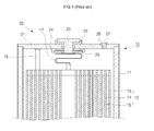
- FIG.1 shows a sectional view of a conventional square type secondary battery 10.
- the secondary battery 10 includes a can 11 housing an electrode assembly 12, and a cap assembly 20 sealing the can 11.
- the electrode assembly 12 includes a cathode electrode plate 13, a separator 14 and an anode electrode plate 15.
- a cathode electrode tap 16 and an anode electrode tap 17 protrude from the cathode electrode plate 13 and the anode electrode plate 15, respectively.
- the cap assembly 20 includes a cap plate 21 coupled with the can 11, an anode terminal 23 insulated from the cap plate 21 by a gasket 22, an insulating plate 24 on an interior-facing surface of the cap plate 21, and a terminal plate 25 electrically connected to the anode terminal 23.
- the cathode electrode tap 16 is electrically connected to the cap plate 21 and the anode electrode tap 17 is electrically connected to the anode terminal 23 through the terminal plate 25.
- an electrolyte injection hole 26 providing a path through which electrolyte may be injected into the can 11 is formed on the cap plate 21.
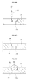
- FIG. 2A shows an electrolyte injection hole before it has been sealed and FIG. 2B shows an electrolyte injection hole of FIG. 2A after it has been sealed.
- the electrolyte injection hole 26 is formed in the cap plate 21 with a taper 28.
- An aluminum ball 27 is placed on the taper 28 to seal the electrolyte injection hole 26 after electrolyte has been injected into the can 11.
- the ball 27 is compressed into the electrolyte injection hole 26 by a pressure device such as a press 1.
- the ball 27 is welded by laser welding to form a weld 29 and seal the electrolyte injection hole 26.
- the configuration of the taper 28 is such that the ball 27 does not always precisely and entirely seal the electrolyte injection hole 26 when the ball is pressed into the hole. Accordingly, electrolyte may leak from the can as indicated by the arrows in FIG. 2B, causing sparking or a potential explosion hazard.
- the electrode assembly in good order of a cathode electrode plate, a separator, and an anode electrode plate is including; a can including a electrode assembly; a terminal union and an electrolyte injection hole formed in a cap plate; coupled with an electrode terminal through the terminal union; the gasket insulated the electrode terminal with settling between the electrode terminal and the cap plate; and the plug sealed the electrolyte injection hole with pressure to the electrolyte injection hole of cap plate; the periphery of the plug coated with synthetic material.
- the secondary battery is including a cathode electrode plate, a separator, and an anode electrode plate; a can including an electrode assembly and an electrolyte; the electrolyte injection hole formed in the one side of a cap plate with closing the opened part of the can; and the plug prevents the electrolyte injection hole of a cap plate; including the film of elasticity material between the plug and the electrolyte injection hole.
- the manufacture method of the secondary battery according to the present invention is including the forming step of an electrode assembly comprising the cathode electrode plate, a separator, and an anode electrode plate; the step of the electrode assembly applied to the opened part of a can and the cap assembly including the cap plate formed the electrolyte injection hole in one side is connecting with the opened part of a can; the step of forming the film to the electrolyte injection hole; the step that the electrolyte pour into the inner side of the can through the electrolyte injection hole formed the film; and the step of sealing the electrolyte injection hole by pressing the ball to the electrolyte injection hole formed the film.
- an exemplary embodiment of a secondary battery 30 includes a can 31 housing an electrode assembly 32, and a cap assembly 40 sealing the can 31.
- the can 31 may have a generally rectangular cross-section and may act as an electrode terminal.
- the electrode assembly 32 includes a cathode electrode plate 33, a separator 34, and an anode electrode plate 35 wound in a jelly-roll configuration.
- the cathode electrode plate 33 includes an aluminum film cathode electrode collector coated on both sides with lithium oxide and the anode electrode plate 34 includes an aluminum film coated on both sides with a carbon material.
- a cathode electrode tap 37 and an anode electrode tap 36 protrude from the cathode electrode plate 33 and the anode electrode plate 35, respectively.
- the cathode electrode tap 37 and the anode electrode tap 36 can be attached to the cathode electrode collector and the anode electrode collector, respectively, by welding. Additionally, the cathode and anode electrode collectors 36, 37 may be wrapped with insulating tape 38 to prevent a short circuit between the cathode electrode plate 33 and the anode electrode plate 35.
- the cap assembly 40 includes a cap plate 41, an insulating plate 46 attached to an interior-facing surface of the cap plate 41, and a terminal plate 47 attached to an interior-facing surface of the insulating plate 46.
- An anode terminal 45 is inserted through the cap plate 41 and the insulating plate 46 and is electrically connected to the terminal plate 47.
- a gasket 44 surrounding the anode terminal 45 insulates the anode terminal from the cap plate 41.
- An insulating case 48 may be attached between the cap assembly 40 and the electrode assembly 32.
- the cathode electrode tap 37 may be attached to the cap plate 41 by welding, and the anode electrode tap 36 may be electrically coupled to the anode terminal 45 by being welded to the terminal plate 47.
- the polarity of the electrodes may also be reversed.
- An electrolyte injection hole 43 allowing an electrolyte to be injected into the can 31 is located on the cap plate 41, the electrolyte injection hole 43 being sealed by a plug 50.
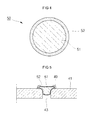
- the plug 50 may include a ball 51 and a resin 52 coated on the periphery of the ball 51.
- the plug 50 may also have a pin configuration.
- the ball 51 is made from aluminum, an aluminum alloy, or stainless steel.
- the resin 52 is fast dry cement resin, and specifically, epoxy resin.
- the epoxy resin may be mixed with a hardener to provide uniform hardening of the resin.
- the amount and type of hardener used may vary resulting in various viscosities, hardening temperatures, hardening times of the resin.
- the sealing of the electrolyte injection hole 43 by the plug 50 will be described with reference to FIG. 5.
- the plug 50 is placed onto the electrolyte injection hole 43 and compressed into the hole.
- the periphery of the plug 50 is laser welded forming a weld 49 adjacent an upper edge of the plug.
- the resin coated on the periphery of the plug 50 rapidly solidifies, seals the plug to the cap plate and helps to form a better seal between the plug and the cap plate 21, thus preventing electrolyte from leaking through the electrolyte injection hole 43.
- a secondary battery 60 includes a can 61 housing an electrode assembly 62, and a cap assembly sealing the can.
- the can 61 may be, for example, aluminum, an aluminum alloy, or iron, may be a hexahedron and may act as an electrode terminal.
- the cathode electrode plate 63 and the anode electrode plate 65 may be substantially similar to the cathode and anode plates described above.
- the separator 64 may be, for example, polyethylene, polypropylene, or a co-polymer of polyethylene and polypropylene. In one exemplary embodiment, the separator 64 may be wider than the cathode electrode plate 63 and the anode electrode plate 65 to prevent a short circuit between the cathode electrode plate 63 and the anode electrode plate 65.
- the cap plate 71 may be a flat type having an opening through which the electrode assembly 62 may be inserted.
- a gasket 72 may insulate the electrode terminal 73 from the cap plate 71.
- An insulating plate 74 may be attached to an interior-facing surface of the cap plate and a terminal plate 75 may be attached to an interior-facing surface of the insulating plate 74.
- the electrode terminal 73 may be electrically coupled with the terminal plate 75 through an opening in the insulating plate 74.
- the cathode electrode tap 66 may be welded to the cap plate 71 and the anode electrode tap 67 may be welded to the electrode terminal 73.
- An insulating case 69 may be located between the electrode assembly 62 and the cap assembly 60 to insulate the electrode assembly from the cap assembly.
- the insulating case 69 may include a high molecule resin, for example, polypropylene.
- An electrolyte injection hole 76 is formed in the cap plate 71 having a stepped configuration in which an upper hole portion has a larger diameter than a lower hole portion.
- a plug 77 is used to seal the electrolyte injection hole 76 by being compressed into the electrolyte injection hole.
- the electrolyte injection hole 76 includes a film 78 formed on the upper hole portion, including a step portion 79.
- the film 78 is formed by drying resin or a rubber liquid solvent on a surface of the electrolyte injection hole 76.
- Exemplary resins may include fluorine resin or polyolefin resin
- exemplary rubber liquid solvents may include fluorine rubber, butadiene rubber, or Isobutylene-Isoprene rubber.
- the electrode assembly including the cathode electrode, the separator and the anode electrode is formed into a jelly-roll configuration (S1). Then, the electrode assembly is inserted into the can (S2). The cap plate is then welded to the can to seal the can (S3) and electrolyte is injected through the electrolyte injection hole (S4). The electrolyte injection hole is then sealed with a plug (S5).
- FIG. 9A a loader 80 including a load 82 is prepared and placed adjacent to an upper hole portion of the electrolyte injection hole 76.
- the load 82 for example, liquid solvent
- the load 82 is ejected from the loader 80 into the electrolyte injection hole 76 to coat an upper hole portion of the electrolyte injection hole.
- the liquid solvent is dried to form a film on the upper hole portion of the electrolyte injection hole 76, including the step portion 79.
- a ball (B) having the same or larger diameter than the electrolyte injection hole 76 is placed on the electrolyte injection hole and compressed. As illustrated in 9E, the electrolyte injection hole 76 is sealed by compressing the plug into the electrolyte injection hole 76. Accordingly, the method of sealing the electrolyte injection hole 76 described above may prevent electrolyte from leaking.
- the secondary battery according to exemplary embodiments of the present invention allows a sufficient seal to be formed between the plug and the electrolyte injection hole during welding of the plug to the cap plate, thus improving the sealing capability of the plug.
- an elastic film such as resin and/or rubber coated on the plug and/or the electrolyte injection hole reduces the likelihood of electrolyte leaking through the plug.
- use of a resin on the electrolyte injection hole may eliminate the need for welding the plug to the cap plate, thus increasing the manufacturing efficiency of the secondary battery.
Landscapes
- Chemical & Material Sciences (AREA)
- Chemical Kinetics & Catalysis (AREA)
- Electrochemistry (AREA)
- General Chemical & Material Sciences (AREA)
- Engineering & Computer Science (AREA)
- Manufacturing & Machinery (AREA)
- Filling, Topping-Up Batteries (AREA)
- Sealing Battery Cases Or Jackets (AREA)
- Secondary Cells (AREA)
Abstract
Description
- The present invention relates to a secondary battery, and more particularly to a secondary battery having an improved electrolyte containment structure.
- Secondary batteries are rechargeable as opposed to primary batteries which are not rechargeable. Secondary batteries are used in electronic devices such as cellular phones, laptop computers, and camcorders. Lithium secondary batteries have high energy density unit per weight and supply 3.6 V of power, three times greater than nickel-cadmium batteries or nickel-hydrogen batteries.
- Lithium secondary batteries use lithium oxide as a cathode electrode active material and carbon materials as anode electrode active materials. Generally, lithium secondary batteries are classified as liquid electrolyte batteries (lithium ion batteries) and high molecule electrolyte batteries (lithium polymer batteries) depending on the type of electrolyte used. Also, lithium secondary batteries may also be classified by their housing, such as cylinder types, square types, and pouch types.
- FIG.1 shows a sectional view of a conventional square type
secondary battery 10. As illustrated in FIG.1, thesecondary battery 10 includes acan 11 housing anelectrode assembly 12, and acap assembly 20 sealing thecan 11. - The
electrode assembly 12 includes acathode electrode plate 13, aseparator 14 and ananode electrode plate 15. A cathode electrode tap 16 and an anode electrode tap 17 protrude from thecathode electrode plate 13 and theanode electrode plate 15, respectively. - The
cap assembly 20 includes acap plate 21 coupled with thecan 11, ananode terminal 23 insulated from thecap plate 21 by agasket 22, aninsulating plate 24 on an interior-facing surface of thecap plate 21, and aterminal plate 25 electrically connected to theanode terminal 23. Thecathode electrode tap 16 is electrically connected to thecap plate 21 and theanode electrode tap 17 is electrically connected to theanode terminal 23 through theterminal plate 25. Additionally, anelectrolyte injection hole 26 providing a path through which electrolyte may be injected into thecan 11 is formed on thecap plate 21. - FIG. 2A shows an electrolyte injection hole before it has been sealed and FIG. 2B shows an electrolyte injection hole of FIG. 2A after it has been sealed. As illustrated in Figures 2A and 2B, the
electrolyte injection hole 26 is formed in thecap plate 21 with ataper 28. Analuminum ball 27 is placed on thetaper 28 to seal theelectrolyte injection hole 26 after electrolyte has been injected into thecan 11. Theball 27 is compressed into theelectrolyte injection hole 26 by a pressure device such as apress 1. Theball 27 is welded by laser welding to form aweld 29 and seal theelectrolyte injection hole 26. - However, the configuration of the
taper 28 is such that theball 27 does not always precisely and entirely seal theelectrolyte injection hole 26 when the ball is pressed into the hole. Accordingly, electrolyte may leak from the can as indicated by the arrows in FIG. 2B, causing sparking or a potential explosion hazard. - To achieve the purpose of the present invention according to one aspect of the secondary battery, the electrode assembly in good order of a cathode electrode plate, a separator, and an anode electrode plate is including; a can including a electrode assembly; a terminal union and an electrolyte injection hole formed in a cap plate; coupled with an electrode terminal through the terminal union; the gasket insulated the electrode terminal with settling between the electrode terminal and the cap plate; and the plug sealed the electrolyte injection hole with pressure to the electrolyte injection hole of cap plate; the periphery of the plug coated with synthetic material.
- In other aspects of the secondary battery according to the present invention, the secondary battery is including a cathode electrode plate, a separator, and an anode electrode plate; a can including an electrode assembly and an electrolyte; the electrolyte injection hole formed in the one side of a cap plate with closing the opened part of the can; and the plug prevents the electrolyte injection hole of a cap plate; including the film of elasticity material between the plug and the electrolyte injection hole.
- Also, the manufacture method of the secondary battery according to the present invention is including the forming step of an electrode assembly comprising the cathode electrode plate, a separator, and an anode electrode plate; the step of the electrode assembly applied to the opened part of a can and the cap assembly including the cap plate formed the electrolyte injection hole in one side is connecting with the opened part of a can; the step of forming the film to the electrolyte injection hole; the step that the electrolyte pour into the inner side of the can through the electrolyte injection hole formed the film; and the step of sealing the electrolyte injection hole by pressing the ball to the electrolyte injection hole formed the film.
- Embodiments of the invention will now be described by way of example with reference to the accompanying drawings, in which:
- FIG. 1 is a sectional view of a portion of a conventional secondary battery.
- FIGs 2A and 2B are sectional views of an electrolyte injection hole of a conventional secondary battery before and after the electrolyte injection hole is sealed by an aluminum ball, respectively.
- FIG. 3 is exploded perspective view of an exemplary embodiment of a secondary battery in accordance with the present invention.
- FIG. 4 is a sectional view of an exemplary embodiment of a plug in accordance with the present invention.
- FIG. 5 is a sectional view of a sealed electrolyte injection hole using the plug of FIG. 4.
- FIG. 6 is a sectional view of a portion of an exemplary secondary battery in accordance with the present invention.
- FIG. 7 is a sectional view of an electrolyte injection hole of the secondary battery of the FIG. 6.
- FIG. 8 is a flow chart of an exemplary manufacturing method of a secondary battery in accordance with the present invention.
- Figures 9A, 9B, 9C, 9D and 9E are sectional views of an electrolyte injection hole being sealed by the manufacturing method of FIG. 8.
- As illustrated in FIG. 3, an exemplary embodiment of a
secondary battery 30 includes acan 31 housing anelectrode assembly 32, and acap assembly 40 sealing thecan 31. Thecan 31 may have a generally rectangular cross-section and may act as an electrode terminal. - The
electrode assembly 32 includes acathode electrode plate 33, aseparator 34, and ananode electrode plate 35 wound in a jelly-roll configuration. Generally, thecathode electrode plate 33 includes an aluminum film cathode electrode collector coated on both sides with lithium oxide and theanode electrode plate 34 includes an aluminum film coated on both sides with a carbon material. - A cathode electrode tap 37 and an anode electrode tap 36 protrude from the
cathode electrode plate 33 and theanode electrode plate 35, respectively. The cathode electrode tap 37 and theanode electrode tap 36 can be attached to the cathode electrode collector and the anode electrode collector, respectively, by welding. Additionally, the cathode andanode electrode collectors cathode electrode plate 33 and theanode electrode plate 35. - The
cap assembly 40 includes acap plate 41, aninsulating plate 46 attached to an interior-facing surface of thecap plate 41, and aterminal plate 47 attached to an interior-facing surface of theinsulating plate 46. - An
anode terminal 45 is inserted through thecap plate 41 and theinsulating plate 46 and is electrically connected to theterminal plate 47. Agasket 44 surrounding theanode terminal 45 insulates the anode terminal from thecap plate 41. Aninsulating case 48 may be attached between thecap assembly 40 and theelectrode assembly 32. - The
cathode electrode tap 37 may be attached to thecap plate 41 by welding, and theanode electrode tap 36 may be electrically coupled to theanode terminal 45 by being welded to theterminal plate 47. However, the polarity of the electrodes may also be reversed. - An
electrolyte injection hole 43 allowing an electrolyte to be injected into thecan 31 is located on thecap plate 41, theelectrolyte injection hole 43 being sealed by aplug 50. As shown in FIG. 4, theplug 50 may include aball 51 and aresin 52 coated on the periphery of theball 51. Theplug 50 may also have a pin configuration. In one exemplary embodiment, theball 51 is made from aluminum, an aluminum alloy, or stainless steel. - In another exemplary embodiment, the
resin 52 is fast dry cement resin, and specifically, epoxy resin. The epoxy resin may be mixed with a hardener to provide uniform hardening of the resin. The amount and type of hardener used may vary resulting in various viscosities, hardening temperatures, hardening times of the resin. - The sealing of the
electrolyte injection hole 43 by theplug 50 will be described with reference to FIG. 5. Theplug 50 is placed onto theelectrolyte injection hole 43 and compressed into the hole. The periphery of theplug 50 is laser welded forming aweld 49 adjacent an upper edge of the plug. The resin coated on the periphery of theplug 50 rapidly solidifies, seals the plug to the cap plate and helps to form a better seal between the plug and thecap plate 21, thus preventing electrolyte from leaking through theelectrolyte injection hole 43. - Another exemplary embodiment of a secondary battery of the present invention will be described with reference to Figures 6 and 7. A
secondary battery 60 includes acan 61 housing anelectrode assembly 62, and a cap assembly sealing the can. Thecan 61 may be, for example, aluminum, an aluminum alloy, or iron, may be a hexahedron and may act as an electrode terminal. Thecathode electrode plate 63 and theanode electrode plate 65 may be substantially similar to the cathode and anode plates described above. - The
separator 64 may be, for example, polyethylene, polypropylene, or a co-polymer of polyethylene and polypropylene. In one exemplary embodiment, theseparator 64 may be wider than thecathode electrode plate 63 and theanode electrode plate 65 to prevent a short circuit between thecathode electrode plate 63 and theanode electrode plate 65. - The
cap plate 71 may be a flat type having an opening through which theelectrode assembly 62 may be inserted. Agasket 72 may insulate theelectrode terminal 73 from thecap plate 71. An insulatingplate 74 may be attached to an interior-facing surface of the cap plate and aterminal plate 75 may be attached to an interior-facing surface of the insulatingplate 74. Theelectrode terminal 73 may be electrically coupled with theterminal plate 75 through an opening in the insulatingplate 74. Thecathode electrode tap 66 may be welded to thecap plate 71 and theanode electrode tap 67 may be welded to theelectrode terminal 73. An insulatingcase 69 may be located between theelectrode assembly 62 and thecap assembly 60 to insulate the electrode assembly from the cap assembly. In one exemplary embodiment, the insulatingcase 69 may include a high molecule resin, for example, polypropylene. - An
electrolyte injection hole 76 is formed in thecap plate 71 having a stepped configuration in which an upper hole portion has a larger diameter than a lower hole portion. Aplug 77 is used to seal theelectrolyte injection hole 76 by being compressed into the electrolyte injection hole. With reference to FIG. 7, theelectrolyte injection hole 76 includes afilm 78 formed on the upper hole portion, including astep portion 79. In one exemplary embodiment, thefilm 78 is formed by drying resin or a rubber liquid solvent on a surface of theelectrolyte injection hole 76. Exemplary resins may include fluorine resin or polyolefin resin, and exemplary rubber liquid solvents may include fluorine rubber, butadiene rubber, or Isobutylene-Isoprene rubber. - An exemplary manufacturing method of a secondary battery of the present invention is described with reference to FIG. 8. First, the electrode assembly including the cathode electrode, the separator and the anode electrode is formed into a jelly-roll configuration (S1). Then, the electrode assembly is inserted into the can (S2). The cap plate is then welded to the can to seal the can (S3) and electrolyte is injected through the electrolyte injection hole (S4). The electrolyte injection hole is then sealed with a plug (S5).
- The steps described with reference to FIG. 8 are illustrated in more detail with reference to Figures 9A to 9E. As illustrated in FIG. 9A, a
loader 80 including aload 82 is prepared and placed adjacent to an upper hole portion of theelectrolyte injection hole 76. As illustrated in Figures 9B and 9C, theload 82, for example, liquid solvent, is ejected from theloader 80 into theelectrolyte injection hole 76 to coat an upper hole portion of the electrolyte injection hole. Next, as illustrated in FIG. 9D, the liquid solvent is dried to form a film on the upper hole portion of theelectrolyte injection hole 76, including thestep portion 79. After electrolyte has been injected into the can, a ball (B) having the same or larger diameter than theelectrolyte injection hole 76 is placed on the electrolyte injection hole and compressed. As illustrated in 9E, theelectrolyte injection hole 76 is sealed by compressing the plug into theelectrolyte injection hole 76. Accordingly, the method of sealing theelectrolyte injection hole 76 described above may prevent electrolyte from leaking. - As described above, the secondary battery according to exemplary embodiments of the present invention allows a sufficient seal to be formed between the plug and the electrolyte injection hole during welding of the plug to the cap plate, thus improving the sealing capability of the plug. Specifically, an elastic film such as resin and/or rubber coated on the plug and/or the electrolyte injection hole reduces the likelihood of electrolyte leaking through the plug. Further, use of a resin on the electrolyte injection hole may eliminate the need for welding the plug to the cap plate, thus increasing the manufacturing efficiency of the secondary battery.
- The present invention is not limited to the exemplary embodiments described herein. Rather, modifications apparent to one of skill in the art may be made within the scope of the invention as claimed in the appended claims.
Claims (17)
- A secondary battery comprising;
an electrode assembly;
a can having an opening at one end of the can, the can housing the electrode assembly;
a cap plate sealing the opening, the cap plate having an electrolyte injection hole for inserting electrolyte into the can; and
a plug for sealing the electrolyte injection hole, the plug having a coating that comprises a sealing material. - The secondary battery of claim 1, wherein the sealing material comprises an elastic film.
- The secondary battery of claim 1 or 2, wherein the sealing material is a resin.
- The secondary battery of claim 3, wherein the resin is a hardening resin.
- The secondary battery of claim 4, wherein the hardening resin is an epoxy resin.
- The secondary battery of any one of the preceding claims, wherein the plug is a ball or a pin.
- The secondary battery of claim 6, wherein the plug is made from aluminum, aluminum alloy, or stainless steel.
- A secondary battery comprising;
an electrode assembly;
a can having an opening at one end of the can, the can housing the electrode assembly;
a cap plate for sealing the opening, the cap plate including an electrolyte injection hole for inserting electrolyte into the can; and
a plug for sealing the electrolyte injection hole;
wherein a sealing layer is located between the electrolyte injection hole and the plug. - The secondary battery of claim 8, wherein the sealing layer comprises an elastic layer.
- The secondary battery of claim 8 or 9,
wherein the electrolyte injection hole has a stepped configuration such that an upper hole portion of the stepped configuration for inputting electrolyte into the can has a diameter larger than a diameter of a lower hole portion adjacent to the upper hole portion; and
wherein the sealing layer coats wall surfaces of the upper hole portion. - The secondary battery of claim 8, 9 or 10, wherein the sealing layer is fluorine resin or polyolefin resin.
- The secondary battery of any one of claims 8 to 11, wherein the sealing layer is fluorine rubber, Butadiene rubber, or Isobutylene-Isoprene rubber.
- A method of manufacturing a secondary battery, the secondary battery including a can having an opening at one end of the can, the method comprising;
providing an electrode assembly;
inserting the electrode assembly into the can through the opening;
sealing the opening with a cap plate, the cap plate having an electrolyte injection hole for inserting electrolyte into the can,
coating the electrolyte injection hole with a sealing layer;
injecting electrolyte into the can through the electrolyte injection hole; and
compressing a plug to seal the electrolyte injection hole such that the plug contacts the sealing layer. - The method of claim 13, wherein the electrolyte injection hole further comprises a stepped configuration such that an upper hole portion of the stepped configuration for inputting electrolyte into the can has a diameter larger than a diameter of a lower hole portion adjacent to the upper hole portion, and wherein coating the electrolyte injection hole with an elastic film further comprises:preparing a loader with a liquid solvent;aiming the loader at the upper hole portion;injecting the liquid solvent into the upper hole portion while moving the loader along a diameter of the electrolyte injection hole; anddrying the liquid solvent to form the sealing layer.
- The method of claim 13 or 14, wherein the sealing layer comprises an elastic film.
- A method of manufacturing a secondary battery, the secondary battery including a can having an opening at one end of the can, the method comprising;
providing an electrode assembly;
inserting the electrode assembly into the can through the opening;
sealing the opening with a cap plate, the cap plate having an electrolyte injection hole for inserting electrolyte into the can,
injecting electrolyte into the can through the electrolyte injection hole; and
compressing a plug to seal the electrolyte injection hole;
wherein the plug includes a sealing layer covering the surface of the plug. - The method of claim 16, wherein the sealing layer comprises a resin.
Applications Claiming Priority (1)
| Application Number | Priority Date | Filing Date | Title |
|---|---|---|---|
| KR1020060027521A KR100898685B1 (en) | 2006-03-27 | 2006-03-27 | Secondary battery |
Publications (3)
| Publication Number | Publication Date |
|---|---|
| EP1840985A2 true EP1840985A2 (en) | 2007-10-03 |
| EP1840985A3 EP1840985A3 (en) | 2009-11-25 |
| EP1840985B1 EP1840985B1 (en) | 2013-08-07 |
Family
ID=38093484
Family Applications (1)
| Application Number | Title | Priority Date | Filing Date |
|---|---|---|---|
| EP07104887.0A Active EP1840985B1 (en) | 2006-03-27 | 2007-03-26 | Secondary battery and method of manufacture |
Country Status (5)
| Country | Link |
|---|---|
| US (2) | US8021774B2 (en) |
| EP (1) | EP1840985B1 (en) |
| JP (1) | JP4809253B2 (en) |
| KR (1) | KR100898685B1 (en) |
| CN (1) | CN100477367C (en) |
Cited By (4)
| Publication number | Priority date | Publication date | Assignee | Title |
|---|---|---|---|---|
| EP2141758A1 (en) | 2008-07-03 | 2010-01-06 | Samsung SDI Co., Ltd. | Sealing Member for an Electrolyte Injection Hole in a Battery, Cap Assembly for a Battery and Method of Fabricating a Secondary Battery |
| EP2775550A4 (en) * | 2012-02-07 | 2015-07-15 | Lg Chemical Ltd | METHOD FOR MANUFACTURING BATTERY ELEMENTS HAVING A NEW STRUCTURE |
| EP3182486A1 (en) * | 2015-12-14 | 2017-06-21 | Samsung SDI Co., Ltd. | Rechargeable battery |
| EP4243107A4 (en) * | 2022-01-24 | 2024-04-24 | Contemporary Amperex Technology Co., Limited | Housing and repair method therefor, related secondary battery, battery module, battery pack, and electric device |
Families Citing this family (16)
| Publication number | Priority date | Publication date | Assignee | Title |
|---|---|---|---|---|
| CN101593824B (en) * | 2008-05-28 | 2013-07-31 | 深圳市比克电池有限公司 | Battery sealing plate and battery |
| CN101626067B (en) * | 2008-07-10 | 2013-01-16 | 深圳市比克电池有限公司 | Connection structure of cell polar ear and cover plate |
| KR101393167B1 (en) | 2009-05-20 | 2014-05-08 | 존슨 컨트롤즈 테크놀로지, 엘엘씨 | Lithium ion battery module |
| KR101174956B1 (en) * | 2009-08-26 | 2012-08-17 | 에스비리모티브 주식회사 | Secondary battery |
| US20110091765A1 (en) * | 2009-10-19 | 2011-04-21 | Samsung Sdi Co., Ltd. | Secondary battery including sealing structure for electrolyte injection hole and method of manufacturing the secondary battery |
| JP5758098B2 (en) * | 2010-09-17 | 2015-08-05 | 株式会社大協精工 | Rubber stopper for pharmaceutical vial |
| KR20120032645A (en) * | 2010-09-29 | 2012-04-06 | 주식회사 동진쎄미켐 | The one-wayness electrolyte injecting hole structure and dye sensitizied solar cell module comprising the same |
| DE102012216477A1 (en) * | 2012-09-14 | 2014-04-10 | Robert Bosch Gmbh | Battery cell with housing cover plate with glued-in sealing plug |
| JP2014170648A (en) * | 2013-03-01 | 2014-09-18 | Sumitomo Electric Ind Ltd | Sealing structure of sealed battery, and sealed battery |
| JP6127960B2 (en) * | 2013-12-24 | 2017-05-17 | 株式会社豊田自動織機 | Temporary sealing jig and method of manufacturing power storage device |
| CN104163298B (en) * | 2014-07-22 | 2016-06-01 | 江苏兆胜空调有限公司 | A kind of controlled atmosphere vegetables and fruits fresh-keeping warehouse peculiar to vessel |
| US10396343B2 (en) | 2015-05-05 | 2019-08-27 | Cps Technology Holdings Llc | Sealing patch for electrolyte fill hole |
| JP2017045660A (en) * | 2015-08-27 | 2017-03-02 | 株式会社豊田自動織機 | Power storage device |
| KR102166475B1 (en) * | 2017-12-14 | 2020-10-16 | 주식회사 엘지화학 | Manufacturing Method of Battery modules |
| CN110299481A (en) * | 2019-07-18 | 2019-10-01 | 常州微宙电子科技有限公司 | A kind of pin type lithium ion battery |
| DE102019134427A1 (en) * | 2019-12-16 | 2021-06-17 | Bayerische Motoren Werke Aktiengesellschaft | Lithium-ion battery with extended service life |
Family Cites Families (20)
| Publication number | Priority date | Publication date | Assignee | Title |
|---|---|---|---|---|
| JPS5888774A (en) | 1981-11-24 | 1983-05-26 | Fuji Photo Film Co Ltd | Electrophotographic information recording method |
| JPS5888774U (en) * | 1981-12-12 | 1983-06-16 | 古河電池株式会社 | Sealed storage battery |
| JPH01119162A (en) | 1987-10-30 | 1989-05-11 | Fujitsu Ltd | Facsimile equipment |
| JPH0441574Y2 (en) * | 1988-02-05 | 1992-09-30 | ||
| JPH0290455A (en) * | 1988-09-27 | 1990-03-29 | Hitachi Maxell Ltd | Cylindrical sealed battery |
| LU90188B1 (en) * | 1997-12-29 | 1998-12-29 | Accumalux S A | An integrated gasket cap for accumulator battery |
| US6190798B1 (en) * | 1998-01-09 | 2001-02-20 | Kabushiki Kaisha Toshiba | Sealed battery and method of manufacturing the same |
| JP2000021437A (en) * | 1998-06-30 | 2000-01-21 | Sanyo Electric Co Ltd | Manufacture of sealed battery |
| JP4110632B2 (en) * | 1998-09-30 | 2008-07-02 | 松下電器産業株式会社 | Sealed battery |
| KR100404887B1 (en) | 1999-01-20 | 2003-11-10 | 주식회사 엘지화학 | Lithium secondary battery |
| JP2000215883A (en) * | 1999-01-27 | 2000-08-04 | Japan Storage Battery Co Ltd | Battery |
| JP4111621B2 (en) * | 1999-03-17 | 2008-07-02 | 三洋電機株式会社 | Sealed battery, sealing plug for sealed battery, and injection hole sealing method |
| JP2001313022A (en) | 2000-04-28 | 2001-11-09 | Japan Storage Battery Co Ltd | Non-aqueous electrolyte secondary battery |
| JP2002298832A (en) | 2001-03-30 | 2002-10-11 | Matsushita Electric Ind Co Ltd | Sealed battery and method for sealing liquid injection hole |
| KR100449763B1 (en) * | 2002-09-11 | 2004-09-22 | 삼성에스디아이 주식회사 | Cap assembly and secondary battery applying the same |
| JP4238645B2 (en) * | 2003-06-12 | 2009-03-18 | 日産自動車株式会社 | Bipolar battery |
| KR100579366B1 (en) * | 2004-01-27 | 2006-05-12 | 삼성에스디아이 주식회사 | Can type secondary battery |
| KR100537538B1 (en) * | 2004-03-30 | 2005-12-16 | 삼성에스디아이 주식회사 | Prismatic type secondary battery having lead plate |
| KR100614397B1 (en) | 2004-10-28 | 2006-08-21 | 삼성에스디아이 주식회사 | Secondary battery |
| KR100686857B1 (en) | 2005-11-02 | 2007-02-26 | 삼성에스디아이 주식회사 | Can type secondary battery and manufacturing method thereof |
-
2006
- 2006-03-27 KR KR1020060027521A patent/KR100898685B1/en not_active Expired - Lifetime
-
2007
- 2007-01-26 JP JP2007015804A patent/JP4809253B2/en active Active
- 2007-03-23 US US11/690,753 patent/US8021774B2/en active Active
- 2007-03-26 EP EP07104887.0A patent/EP1840985B1/en active Active
- 2007-03-27 CN CNB2007100869568A patent/CN100477367C/en active Active
-
2010
- 2010-06-15 US US12/816,330 patent/US8092938B2/en active Active
Non-Patent Citations (1)
| Title |
|---|
| None |
Cited By (7)
| Publication number | Priority date | Publication date | Assignee | Title |
|---|---|---|---|---|
| EP2141758A1 (en) | 2008-07-03 | 2010-01-06 | Samsung SDI Co., Ltd. | Sealing Member for an Electrolyte Injection Hole in a Battery, Cap Assembly for a Battery and Method of Fabricating a Secondary Battery |
| US9209437B2 (en) | 2008-07-03 | 2015-12-08 | Samsung Sdi Co., Ltd. | Secondary battery having electrolyte injection hole and method of fabricating the same |
| EP2775550A4 (en) * | 2012-02-07 | 2015-07-15 | Lg Chemical Ltd | METHOD FOR MANUFACTURING BATTERY ELEMENTS HAVING A NEW STRUCTURE |
| US9774060B2 (en) | 2012-02-07 | 2017-09-26 | Lg Chem, Ltd. | Method for manufacturing battery cell of novel structure |
| EP3182486A1 (en) * | 2015-12-14 | 2017-06-21 | Samsung SDI Co., Ltd. | Rechargeable battery |
| US10193131B2 (en) | 2015-12-14 | 2019-01-29 | Samsung Sdi Co., Ltd. | Rechargeable battery |
| EP4243107A4 (en) * | 2022-01-24 | 2024-04-24 | Contemporary Amperex Technology Co., Limited | Housing and repair method therefor, related secondary battery, battery module, battery pack, and electric device |
Also Published As
| Publication number | Publication date |
|---|---|
| CN100477367C (en) | 2009-04-08 |
| US8092938B2 (en) | 2012-01-10 |
| CN101047265A (en) | 2007-10-03 |
| JP4809253B2 (en) | 2011-11-09 |
| KR100898685B1 (en) | 2009-05-22 |
| US20100255367A1 (en) | 2010-10-07 |
| EP1840985A3 (en) | 2009-11-25 |
| US8021774B2 (en) | 2011-09-20 |
| US20070224491A1 (en) | 2007-09-27 |
| EP1840985B1 (en) | 2013-08-07 |
| JP2007265967A (en) | 2007-10-11 |
| KR20070096643A (en) | 2007-10-02 |
Similar Documents
| Publication | Publication Date | Title |
|---|---|---|
| US8021774B2 (en) | Secondary battery and method of fabricating the same | |
| KR100984367B1 (en) | Secondary battery comprising Electrolyte Injection-hole and Fabricating method the same | |
| KR100449763B1 (en) | Cap assembly and secondary battery applying the same | |
| KR100467698B1 (en) | Cylindrical type lithium secondary battery and the fabrication method of the same | |
| EP1826840A2 (en) | Secondary battery and method of manufacture | |
| KR20110029061A (en) | Secondary battery | |
| KR100303826B1 (en) | Secondary Battery Cap Assembly | |
| KR100696791B1 (en) | Cap assembly and a lithium ion secondary battery having the same | |
| KR100719740B1 (en) | Secondary Battery and Manufacturing Method Thereof | |
| KR100646520B1 (en) | Secondary Battery and Its Assembly Method | |
| KR100822193B1 (en) | Cap assembly and secondary battery using the same | |
| KR100787417B1 (en) | Secondary battery | |
| KR100686857B1 (en) | Can type secondary battery and manufacturing method thereof | |
| KR101023871B1 (en) | Lithium secondary battery | |
| KR100686831B1 (en) | Secondary Battery and Manufacturing Method of Secondary Battery Using the Same | |
| KR100670428B1 (en) | Secondary battery | |
| KR100760786B1 (en) | Secondary Battery and Manufacturing Method Using Same | |
| KR20070101568A (en) | Lithium secondary battery | |
| KR100659827B1 (en) | Cap assembly and secondary battery having same | |
| KR100858797B1 (en) | Cap assembly and secondary battery using the same | |
| KR101222255B1 (en) | Secondary battery | |
| KR100561307B1 (en) | Secondary battery | |
| KR100670516B1 (en) | Secondary Battery and Manufacturing Method of Secondary Battery Using the Same | |
| KR20060019768A (en) | Wound electrode assembly | |
| KR101042822B1 (en) | Assembly method of cap assembly. |
Legal Events
| Date | Code | Title | Description |
|---|---|---|---|
| PUAI | Public reference made under article 153(3) epc to a published international application that has entered the european phase |
Free format text: ORIGINAL CODE: 0009012 |
|
| 17P | Request for examination filed |
Effective date: 20070326 |
|
| AK | Designated contracting states |
Kind code of ref document: A2 Designated state(s): AT BE BG CH CY CZ DE DK EE ES FI FR GB GR HU IE IS IT LI LT LU LV MC MT NL PL PT RO SE SI SK TR |
|
| AX | Request for extension of the european patent |
Extension state: AL BA HR MK YU |
|
| RAP1 | Party data changed (applicant data changed or rights of an application transferred) |
Owner name: SAMSUNG SDI CO., LTD. |
|
| PUAL | Search report despatched |
Free format text: ORIGINAL CODE: 0009013 |
|
| AK | Designated contracting states |
Kind code of ref document: A3 Designated state(s): AT BE BG CH CY CZ DE DK EE ES FI FR GB GR HU IE IS IT LI LT LU LV MC MT NL PL PT RO SE SI SK TR |
|
| AX | Request for extension of the european patent |
Extension state: AL BA HR MK RS |
|
| AKX | Designation fees paid |
Designated state(s): FR GB HU |
|
| REG | Reference to a national code |
Ref country code: DE Ref legal event code: 8566 |
|
| 17Q | First examination report despatched |
Effective date: 20100921 |
|
| REG | Reference to a national code |
Ref country code: DE Ref legal event code: R079 Free format text: PREVIOUS MAIN CLASS: H01M0002020000 Ipc: H01M0002360000 |
|
| RIC1 | Information provided on ipc code assigned before grant |
Ipc: H01M 2/08 20060101ALI20121218BHEP Ipc: H01M 2/36 20060101AFI20121218BHEP Ipc: H01M 10/04 20060101ALI20121218BHEP Ipc: H01M 2/02 20060101ALI20121218BHEP |
|
| GRAP | Despatch of communication of intention to grant a patent |
Free format text: ORIGINAL CODE: EPIDOSNIGR1 |
|
| GRAS | Grant fee paid |
Free format text: ORIGINAL CODE: EPIDOSNIGR3 |
|
| GRAA | (expected) grant |
Free format text: ORIGINAL CODE: 0009210 |
|
| AK | Designated contracting states |
Kind code of ref document: B1 Designated state(s): FR GB HU |
|
| REG | Reference to a national code |
Ref country code: GB Ref legal event code: FG4D |
|
| PLBE | No opposition filed within time limit |
Free format text: ORIGINAL CODE: 0009261 |
|
| STAA | Information on the status of an ep patent application or granted ep patent |
Free format text: STATUS: NO OPPOSITION FILED WITHIN TIME LIMIT |
|
| 26N | No opposition filed |
Effective date: 20140508 |
|
| REG | Reference to a national code |
Ref country code: FR Ref legal event code: PLFP Year of fee payment: 10 |
|
| PG25 | Lapsed in a contracting state [announced via postgrant information from national office to epo] |
Ref country code: HU Free format text: LAPSE BECAUSE OF FAILURE TO SUBMIT A TRANSLATION OF THE DESCRIPTION OR TO PAY THE FEE WITHIN THE PRESCRIBED TIME-LIMIT; INVALID AB INITIO Effective date: 20070326 |
|
| REG | Reference to a national code |
Ref country code: FR Ref legal event code: PLFP Year of fee payment: 11 |
|
| REG | Reference to a national code |
Ref country code: FR Ref legal event code: PLFP Year of fee payment: 12 |
|
| P01 | Opt-out of the competence of the unified patent court (upc) registered |
Effective date: 20230528 |
|
| PGFP | Annual fee paid to national office [announced via postgrant information from national office to epo] |
Ref country code: GB Payment date: 20260303 Year of fee payment: 20 |
|
| PGFP | Annual fee paid to national office [announced via postgrant information from national office to epo] |
Ref country code: FR Payment date: 20260309 Year of fee payment: 20 |