EP1840921B1 - Fluid level switch - Google Patents
Fluid level switch Download PDFInfo
- Publication number
- EP1840921B1 EP1840921B1 EP07005940A EP07005940A EP1840921B1 EP 1840921 B1 EP1840921 B1 EP 1840921B1 EP 07005940 A EP07005940 A EP 07005940A EP 07005940 A EP07005940 A EP 07005940A EP 1840921 B1 EP1840921 B1 EP 1840921B1
- Authority
- EP
- European Patent Office
- Prior art keywords
- float
- fluid
- level switch
- fluid level
- mounting plate
- Prior art date
- Legal status (The legal status is an assumption and is not a legal conclusion. Google has not performed a legal analysis and makes no representation as to the accuracy of the status listed.)
- Not-in-force
Links
- 239000012530 fluid Substances 0.000 title claims description 127
- 239000012212 insulator Substances 0.000 claims description 14
- 230000033001 locomotion Effects 0.000 claims description 13
- 239000011810 insulating material Substances 0.000 claims description 2
- 230000000717 retained effect Effects 0.000 claims description 2
- 230000000007 visual effect Effects 0.000 claims description 2
- 239000003921 oil Substances 0.000 description 28
- 239000003990 capacitor Substances 0.000 description 5
- 238000004891 communication Methods 0.000 description 3
- 239000004020 conductor Substances 0.000 description 3
- 230000008878 coupling Effects 0.000 description 3
- 238000010168 coupling process Methods 0.000 description 3
- 238000005859 coupling reaction Methods 0.000 description 3
- 238000000034 method Methods 0.000 description 3
- 238000010276 construction Methods 0.000 description 2
- 230000000694 effects Effects 0.000 description 2
- 239000000446 fuel Substances 0.000 description 2
- 239000000463 material Substances 0.000 description 2
- 238000004804 winding Methods 0.000 description 2
- XUIMIQQOPSSXEZ-UHFFFAOYSA-N Silicon Chemical compound [Si] XUIMIQQOPSSXEZ-UHFFFAOYSA-N 0.000 description 1
- 230000005540 biological transmission Effects 0.000 description 1
- 238000002485 combustion reaction Methods 0.000 description 1
- 230000007423 decrease Effects 0.000 description 1
- 230000001419 dependent effect Effects 0.000 description 1
- 230000005484 gravity Effects 0.000 description 1
- 238000005461 lubrication Methods 0.000 description 1
- 238000000465 moulding Methods 0.000 description 1
- 230000011664 signaling Effects 0.000 description 1
- 229910052710 silicon Inorganic materials 0.000 description 1
- 239000010703 silicon Substances 0.000 description 1
Images

Classifications
-
- H—ELECTRICITY
- H01—ELECTRIC ELEMENTS
- H01H—ELECTRIC SWITCHES; RELAYS; SELECTORS; EMERGENCY PROTECTIVE DEVICES
- H01H35/00—Switches operated by change of a physical condition
- H01H35/18—Switches operated by change of liquid level or of liquid density, e.g. float switch
-
- G—PHYSICS
- G01—MEASURING; TESTING
- G01F—MEASURING VOLUME, VOLUME FLOW, MASS FLOW OR LIQUID LEVEL; METERING BY VOLUME
- G01F23/00—Indicating or measuring liquid level or level of fluent solid material, e.g. indicating in terms of volume or indicating by means of an alarm
- G01F23/30—Indicating or measuring liquid level or level of fluent solid material, e.g. indicating in terms of volume or indicating by means of an alarm by floats
- G01F23/303—Indicating or measuring liquid level or level of fluent solid material, e.g. indicating in terms of volume or indicating by means of an alarm by floats characterised by means to prevent fault-level readings due to turbulence of the fluid, e.g. special float housings
-
- G—PHYSICS
- G01—MEASURING; TESTING
- G01F—MEASURING VOLUME, VOLUME FLOW, MASS FLOW OR LIQUID LEVEL; METERING BY VOLUME
- G01F23/00—Indicating or measuring liquid level or level of fluent solid material, e.g. indicating in terms of volume or indicating by means of an alarm
- G01F23/30—Indicating or measuring liquid level or level of fluent solid material, e.g. indicating in terms of volume or indicating by means of an alarm by floats
- G01F23/64—Indicating or measuring liquid level or level of fluent solid material, e.g. indicating in terms of volume or indicating by means of an alarm by floats of the free float type without mechanical transmission elements
- G01F23/68—Indicating or measuring liquid level or level of fluent solid material, e.g. indicating in terms of volume or indicating by means of an alarm by floats of the free float type without mechanical transmission elements using electrically actuated indicating means
- G01F23/70—Indicating or measuring liquid level or level of fluent solid material, e.g. indicating in terms of volume or indicating by means of an alarm by floats of the free float type without mechanical transmission elements using electrically actuated indicating means for sensing changes in level only at discrete points
- G01F23/703—Indicating or measuring liquid level or level of fluent solid material, e.g. indicating in terms of volume or indicating by means of an alarm by floats of the free float type without mechanical transmission elements using electrically actuated indicating means for sensing changes in level only at discrete points using electromechanically actuated indicating means
-
- G—PHYSICS
- G01—MEASURING; TESTING
- G01F—MEASURING VOLUME, VOLUME FLOW, MASS FLOW OR LIQUID LEVEL; METERING BY VOLUME
- G01F23/00—Indicating or measuring liquid level or level of fluent solid material, e.g. indicating in terms of volume or indicating by means of an alarm
- G01F23/30—Indicating or measuring liquid level or level of fluent solid material, e.g. indicating in terms of volume or indicating by means of an alarm by floats
- G01F23/76—Indicating or measuring liquid level or level of fluent solid material, e.g. indicating in terms of volume or indicating by means of an alarm by floats characterised by the construction of the float
Definitions
- the present invention relates to fluid level sensors, and more specifically to low oil sensors for engines.
- Fluid level sensors are generally used to determine the level of fluid retained within an enclosure. Some fluid level sensors activate an indicator when the fluid level decreases below a desired fluid level while others automatically shut off the system using the fluid.
- fluid level sensors are positioned directly in a fluid reservoir, or within a smaller enclosure in fluid communication with the fluid reservoir.
- the enclosure maintains a fluid level proportional to the amount of fluid in the reservoir.
- a fluid level sensor is a sensor for the oil level within the crankcase of an internal combustion engine. The engine requires a desired amount of oil within the crankcase to properly lubricate the engine during operation. If the oil level is too low, the engine can be damaged due to improper lubrication.
- a fluid level sensor can be used to determine when the oil level within the crankcase is below a desired level.
- Prior art systems often employ the use of a float within a housing to move with the level of fluid as the level of fluid changes.
- a sensor or an electrical contact can be positioned in the vicinity of the float and can be used to detect when the level of fluid is not within a desired range.
- the sensor or contact can communicate the condition of the fluid level through a indicator such as a warning light or by automatically shutting off the device that is using the fluid to operate.
- the float can complete an electrical connection between a ground and an ignition contact to shut off the engine when the float is in a position indicative of low fluid or complete an electrical circuit for an audible indicator or visual indicator.
- a fluid level switch for a machine having a fluid reservoir adapted to contain a fluid at an acceptable level
- the fluid level switch comprising a mounting plate retaining first and second contacts, a float housing configured to receive fluid from the fluid reservoir, and a float assembly positioned within the float housing and movable in response to the level of fluid in the float housing, the float assembly including a contact member electrically connecting the first and second contacts when the level of the fluid is below the acceptable level, the contact member coupled to the float for movement with the float and for movement relative to the float.
- the present invention provides a fluid level switch in accordance with independent claim 1. Preferred embodiments of the invention are reflected in the dependent claims.
- the present invention is directed to a low fluid sensor that can be mounted to an engine or other machine to accurately detect a condition of low fluid.
- the apparatus can include a float contact that compensates for the movement of a float due to splashing of fluid in a reservoir for a system that has moving parts.
- a float contact that is movable relative to the float allows the low fluid sensor to more accurately determine a low fluid condition and limit the incidence of intermittent grounding of the ignition.
- a movable float contact allows for tolerance or dimensional variations of the contacts. In the case that the contacts are not exactly the same size or height, the moveable plate is still capable of touching all of the contacts simultaneously. Additionally, a movable float contact can remain in contact with the ground and ignition contact even while the float is moving in response to vibrations, because the float contact is weighted and loosely coupled to the float so that the float contact does not move with every slight dip and peak of the float. Instead, the plate will continue to contact the electrical contacts and therefore allow the low fluid indicator to remain in a "shut-off" state until more fluid is added to the system.
- One embodiment of the present invention is directed to a fluid level switch for a machine having a fluid reservoir adapted to contain a fluid at an acceptable level.
- the fluid level switch includes a mounting plate, a float housing, and a float assembly positioned within the float housing.
- the mounting plate retains first and second contacts.
- the float housing is configured to receive fluid from the fluid reservoir and the float assembly is movable in response to the level of fluid in the float housing.
- the float assembly includes a contact member electrically connecting the contacts when the level of the fluid is below the acceptable level. The contact member is coupled to the float for movement with the float and for movement relative to the float.
- the fluid level switch for a machine having a fluid reservoir adapted to contain a fluid at an acceptable level.
- the fluid level switch includes first and second contacts, and a float assembly adapted to be in fluid communication with the fluid reservoir.
- the float assembly includes a float and a contact member. The float is movable between a raised position when the fluid is at an acceptable level and a lowered position when the fluid is below the acceptable level.
- the contact member is coupled to the float about at least a portion of the periphery of the contact member. The contact member electrically connects the first and second contacts when the fluid is below the acceptable level.
- the fluid level switch includes a float housing, first and second contacts, and a float assembly.
- the float housing is configured to receive fluid from the fluid reservoir, and the first and second contacts are positioned on a same side of the float housing.
- the float assembly is positioned within the float housing and includes a float and a contact member. The float is movable between a raised position when the fluid is at an acceptable level and a lowered position when the fluid is below the acceptable level.
- the contact member is coupled to the float for movement with the float between raised and lowered positions and for movement relative to the float.
- the contact member electrically connects the first and second contacts in at least one of the raised and lowered condition.
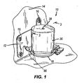
- FIG. 1 is a perspective view of a fluid level switch according to a first embodiment of the present invention.
- FIG. 2 is an exploded view of the fluid level switch of FIG. 1 .
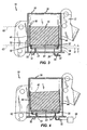
- FIG. 3 is cross-sectional view taken along line 3-3 of FIG. 1 ;
- FIG. 4 is a view similar to FIG. 3 illustrating a float in a tilted condition.
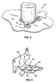
- FIG. 5 is a perspective view of a fluid level switch according to another embodiment of the present invention.
- FIG. 6 is a perspective view of a mounting plate according to another embodiment of the present invention.
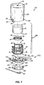
- FIG. 7 is an exploded view of a fluid level switch according to another embodiment of the present invention.
- FIG. 1 A fluid level switch 10 of a first embodiment of the present invention is illustrated in FIG. 1 .
- the fluid level switch 10 includes a mounting plate 12 fastened to a vertical wall 14 of an engine by mounting screws 16. Any conventional fastener can be employed to secure the mounting plate 12 to the vertical wall 14 as just described, such as screws, nails, rivets, pins, posts, clips, clamps, inter-engaging elements, and any combination of such fasteners.
- the mounting plate 12 is L-shaped to include a support portion 18. As shown in FIG. 2 , the support portion 18 includes three apertures 20, however, the number of apertures 20 can vary.
- the support portion 18 comprises two electrical contacts 22, 24.
- the first electrical contact such as a ground contact 22 is made from a piece of the support portion 18 that has been bent upwardly a distance from the surface of the support portion 18, thereby forming an aperture 23.
- the second electrical contact is an ignition contact 24 that is made up of a conductive material and that extends through an aperture 26 in the support portion 18.
- an insulator 28 supports the ignition contact 24 and is press-fit into an aperture 29 of the support portion 18.
- the insulator 28 can be coupled to the support portion 18 in various ways such as the use of fasteners or molding. The insulator 28 acts to prevent electrical contact between the ground contact 22 and the ignition contact 24.
- the fluid level switch 10 also includes a cylindrical float housing 30 with protrusions 32 that line up with the apertures 20 for coupling the float housing 30 to the support portion 18.
- the float housing 30 has an open end 34 where the protrusions 32 are located and a closed end 36 having a centrally located aperture 38. In other embodiments, the aperture 38 could be located anywhere on the closed end to vent for air.
- a gap or cutout 40 in the float housing 30 provides clearance for the insulator 28 when the float housing 30 is coupled to the support portion 18 and allows for a snap-fit assembly.
- the insulator 28 is partially located within the float housing 30 to reduce the size of the fluid level switch 10. The location of the insulator 28 can vary and is not limited to the placement shown in FIG. 2 . Specifically, the insulator 28 does not have to be located partially within the float housing 30.
- FIGS. 2 and 3 A cylindrical float 42 made of a buoyant material is shown in FIGS. 2 and 3 .
- the float 42 is held in a retaining member 44 having a cage structure. Both a bottom portion 46 and a top portion 48 of the retaining member 44 are open.
- the retaining member 44 has a plurality of tabs 50 on the top portion 48 that can retain the float 42 within the retaining member 44.
- the float 42 rests on a first lip 52 that includes an outer diameter 54 equal to the upper portion 48 of the retaining member 44 and an inner diameter 55 smaller than that of the float 42.
- the first lip 52 thereby supports the bottom 57 of the float 42.
- a plate 56 can be positioned between the float 42 and the bottom portion 46 of the retaining member 44.
- the plate 56 sits on a second lip 58 on the bottom portion 46 of the retaining member 44.
- the second lip 58 is spaced from the first lip 52 a distance D to allow movement of the plate 56 (having a thickness T) relative to the float 42 within the retaining member 44.
- the plate 56 is disc-shaped and has apertures 60 for weight adjustment.
- a centrally located, raised portion 61 of the plate 56 helps to prevent the plate 56 from becoming stuck to the float 42 due to viscous properties of the fluid.
- the raised portion allows only a small portion of the plate 56 to contact the float 42.
- the plate 56 also referred to as a contact plate, is not limited to the illustrated shape, but can take on a plurality of shapes and sizes such that it can provide electrical communication between two contacts. It is preferable that the plate 56 be more dense than the fluid, however it is not required. In the preferred embodiment, gravity pulls the plate 56 down on the contacts 22, 24.
- FIG. 3 illustrates the internal structure of the fluid level switch 10.
- the plate 56 rests upon the second lip 58 of the retaining member 44. Between the top of the plate 56 and the bottom 57 of the float 42 is a space 62. The space 62 allows linear and angular motion of the plate 56 to help improve switching characteristics.
- the bottom 57 of the float 42 rests upon the first lip 52 of the retaining member 44, and is held at the top portion 48 of the retaining member 44 by the tabs 50.
- the float 42, plate 56, and retaining member 44 define a float assembly 64 ( Fig. 2 ).
- the float assembly 64 fits within the cylindrical float housing 30. As shown in FIGS. 1 and 2 , the protrusions 32 of the float housing 30 engage the apertures 20 to cover contacts 22, 24. The gap 40 in the float housing 30 prevents interference from the insulator 28 when the float housing 30 is coupled to the support portion 18.
- a first side of the float housing 30 is defined below the float 42, and everything located below reference line 63 is considered to be below the float 42.
- a second side of the float housing 30 is defined above the float 42, and everything located above reference line 65 is considered to be above the float 42. As illustrated in Fig. 3 , both contacts 22, 24 are below the float 42 and on the first side of the housing 30.
- One embodiment of the present invention can be located in the crankcase of an engine.
- the crankcase is a relatively turbulent environment and the level of fluid, such as oil, may fluctuate greatly depending on a number of factors, such as slight tilting or changes to the orientation of the engine and the crankshaft or other moving parts splashing the oil.
- Other embodiments could be used on pumps, transmissions, or any other machine with moving parts and a fluid reservoir.
- the fluid level switch 10 allows oil to flow into and out of the float housing 30 through the apertures 23, 26, 38.
- the protrusions 32 of the float housing 30 may have apertures 66 as well to allow for fluid flow into the float housing 30. Since the float 42 is made of a buoyant material, the float 42 will cause the float assembly 64 to rise and fall with the oil level. When oil is added to the engine, the float assembly 64 will rise with the level of the oil. As oil is used in the system, the float assembly 64 will lower with the oil level.
- the float assembly 64 and hence the plate 56 move increasingly closer to the contacts 22, 24, as shown in FIG. 3 .
- the plate 56 touches the contacts 22, 24. Because the plate 56 is more dense than the fluid being monitored, the plate 56 will tend to stay in relatively the same position although the plate 56, in most situations, is submerged in fluid. As shown in FIG.
- the space 62 between the plate 56 and the float 42 is intended to be large enough to allow the plate 56 to remain in contact with electrical contacts 22, 24 even while the float 42 and retaining member 44 move and tilt inside the cylindrical float housing 30 caused by misaligned contacts 22, 24 or agitated fluid from normal engine vibration or operation.
- the illustrated embodiment uses an "engine shutdown” method by grounding the primary ignition current when the plate 56 is touching both contacts 22, 24.
- the operator of a lawnmower or snow blower can be alerted of such a situation through the engine being shut-off during operation.
- the engine can be restarted and regular operation can resume.
- An alternate design for the fluid level switch 10 uses an "indicator method" to alert an operator of the low oil situation.
- an electrical circuit can be completed to alert the operator of a low oil situation through an indicator such as a "low oil” light or a “low oil” alarm or buzzer.
- the "low oil” indicator is activated, the operator knows that a low oil situation is occurring. In that case, the operator can choose to continue operating the machine while in a state of low oil and risk damaging the engine, or can add oil until the plate 56 is no longer touching the contacts 22, 24.
- a latching module 68 (illustrated in Fig. 4 ) can be used to prevent intermittent or false shutdown due to switch bouncing caused by engine vibration and turbulence of the fluid surrounding the float assembly 64. False shutdown occurs when vibration and turbulence of the engine and fluid do not allow the float to ground the ignition long enough to completely shut down the engine.
- the latching module 68 operates to ground the ignition even after the plate 56 bounces out of contact with the first and second contacts 22, 24.
- the latching module 68 includes a capacitor and a silicon controlled rectifier ("SCR”) electrically connected to the capacitor.
- the ignition pulse from the engine's ignition system charges the capacitor.
- the charge of the capacitor reaches a voltage value that is sufficiently high to switch the SCR "on”
- the primary winding current is shunted through the SCR to ground, thereby shutting down the engine.
- the SCR remains “on”, using the energy stored in the capacitor as the engine rotates during coastdown. As long as the SCR is "on”, the primary winding current will remain shunted through the SCR regardless of whether the fluid level switch re-opens due to vibrations.
- a fluid level switch 110 according to an alternate embodiment of the present invention is illustrated in FIG. 5 .
- the fluid level switch 110 is adapted for mounting to a horizontal surface 114 using mounting fasteners 116.
- a mounting plate 112 can be fastened to the horizontal surface 114 in the same manner that the first embodiment of the mounting plate 12 can be fastened to a vertical surface 14.
- Mounting plate 112 is similar to the support portion 18 as shown in FIG. 1 and the fluid level switch 110 operates similar to fluid level switch 10.
- FIG. 6 Another embodiment of a mounting plate 212 is illustrated in FIG. 6 .
- the mounting plate 212 is adapted to be fastened to a vertical surface 14 similar to the mounting plate 12 illustrated in FIG. 1 .
- the mounting plate 212 has a support portion 218 that comprises three electrical contacts 222, 268, 24 (shown in FIG. 2 ).
- the electrical contacts, such as ground contacts 222, 268, are made from pieces of the support portion 218 that have been bent upwardly a distance from the surface of the support portion 218 thereby forming apertures 223, 270.
- the electrical contact 24 is made of conductive material and extends through an aperture 226 in the support portion 218.
- the mounting plate 212 used with the float assembly 64 is similar to the mounting plates 12, 112 illustrated in FIGS. 1-5 . In other embodiments, the mounting plate 212 can be reconfigured to be fastened to a horizontal surface 114 similar to the mounting plate 112 illustrated in FIG. 5 .
- a fluid level switch 310 of another embodiment of the present invention is illustrated in FIG. 7 .
- the fluid level switch 310 includes a mounting plate 312 that can fastened to a wall of an engine by inserting fasteners through apertures 316.
- the mounting plate 312 includes a support portion 318 that has two electrical contacts 322, 368.
- the electrical contacts 322, 368 can be ground contacts and are made from pieces of the support portion 318 that have been bent upwardly a distance from the surface of the support portion 318 thereby forming apertures 323, 370.
- the fluid level switch 310 also includes an electrical contact 324 that extends through an aperture 326 in the support portion 318.
- the electrical contact 324 can be an ignition contact and is made from a conductive material.
- the ignition contact extends through the aperture 326 in the support portion 318 such that the ignition contact does not contact the mounting plate 312.
- a shield 328 supports the ignition contact 324 and is coupled to the mounting plate 312 by the protrusions 332 of the float housing 330.
- the protrusions 332 of the float housing 330 extend through the apertures 320 of the mounting plate 312 and into apertures 334 of the shield 328 to couple the mounting plate 312 between the float housing 330 and the shield 328.
- the shield 328 reduces the effect of oil turbulence within the oil reservoir on the operation of the fuel level switch 310.
- the shield 328 resists the flow of oil through apertures 323, 370 making the operation of the plate 56 and float 42 less affected by the turbulence outside the float housing 330.
- the shield 328 is made of an insulating material.
- the shield 328 replaces the insulator 28, 128 of the previous embodiments ( Figs. 1-6 ) to support the ignition contact 324 and to prevent electrical contact between the ignition contact 324 and the ground contacts 322, 368 and between the ignition contact 324 and the mounting plate 312.
- the fluid level switch 310 also includes a float assembly 364 similar to the float assembly 64 of the first embodiment as illustrated in FIG. 2 except that the protrusions 332 of the float housing 330 are slightly extended to capture the shield 328.
- the reference numbers used to describe the float assembly 64 of FIG. 2 are used to describe the corresponding components of the float assembly 364 in FIG. 7 .
Landscapes
- Physics & Mathematics (AREA)
- Fluid Mechanics (AREA)
- General Physics & Mathematics (AREA)
- Level Indicators Using A Float (AREA)
Description
- The present invention relates to fluid level sensors, and more specifically to low oil sensors for engines.
- Fluid level sensors are generally used to determine the level of fluid retained within an enclosure. Some fluid level sensors activate an indicator when the fluid level decreases below a desired fluid level while others automatically shut off the system using the fluid.
- In operation, fluid level sensors are positioned directly in a fluid reservoir, or within a smaller enclosure in fluid communication with the fluid reservoir. The enclosure maintains a fluid level proportional to the amount of fluid in the reservoir. One example of an application of a fluid level sensor is a sensor for the oil level within the crankcase of an internal combustion engine. The engine requires a desired amount of oil within the crankcase to properly lubricate the engine during operation. If the oil level is too low, the engine can be damaged due to improper lubrication. A fluid level sensor can be used to determine when the oil level within the crankcase is below a desired level.
- Prior art systems often employ the use of a float within a housing to move with the level of fluid as the level of fluid changes. A sensor or an electrical contact can be positioned in the vicinity of the float and can be used to detect when the level of fluid is not within a desired range. The sensor or contact can communicate the condition of the fluid level through a indicator such as a warning light or by automatically shutting off the device that is using the fluid to operate. For example, the float can complete an electrical connection between a ground and an ignition contact to shut off the engine when the float is in a position indicative of low fluid or complete an electrical circuit for an audible indicator or visual indicator.
- The use of such a system is generally reliable in shutting off the engine when a low amount of fluid is present. However, signaling a low fluid condition can be inconsistent due to the effect of the vibrations caused by moving parts of the engine, for example. This causes the fluid to move and splash around in the reservoir, thereby causing movement of the float and an unstable contact between the ground and ignition contact. This movement has the potential to prevent the float from grounding the ignition long enough to completely shut down the engine.
- Further information pertaining to the prior art can be found in
DE 18 21 034 - The present invention provides a fluid level switch in accordance with independent claim 1. Preferred embodiments of the invention are reflected in the dependent claims.
- In some embodiments, the present invention is directed to a low fluid sensor that can be mounted to an engine or other machine to accurately detect a condition of low fluid. The apparatus can include a float contact that compensates for the movement of a float due to splashing of fluid in a reservoir for a system that has moving parts.
- Using a float contact that is movable relative to the float allows the low fluid sensor to more accurately determine a low fluid condition and limit the incidence of intermittent grounding of the ignition. A movable float contact allows for tolerance or dimensional variations of the contacts. In the case that the contacts are not exactly the same size or height, the moveable plate is still capable of touching all of the contacts simultaneously. Additionally, a movable float contact can remain in contact with the ground and ignition contact even while the float is moving in response to vibrations, because the float contact is weighted and loosely coupled to the float so that the float contact does not move with every slight dip and peak of the float. Instead, the plate will continue to contact the electrical contacts and therefore allow the low fluid indicator to remain in a "shut-off" state until more fluid is added to the system.
- One embodiment of the present invention is directed to a fluid level switch for a machine having a fluid reservoir adapted to contain a fluid at an acceptable level. The fluid level switch includes a mounting plate, a float housing, and a float assembly positioned within the float housing. The mounting plate retains first and second contacts. The float housing is configured to receive fluid from the fluid reservoir and the float assembly is movable in response to the level of fluid in the float housing. The float assembly includes a contact member electrically connecting the contacts when the level of the fluid is below the acceptable level. The contact member is coupled to the float for movement with the float and for movement relative to the float.
- Another embodiment of the invention is directed to a fluid level switch for a machine having a fluid reservoir adapted to contain a fluid at an acceptable level. The fluid level switch includes first and second contacts, and a float assembly adapted to be in fluid communication with the fluid reservoir. The float assembly includes a float and a contact member. The float is movable between a raised position when the fluid is at an acceptable level and a lowered position when the fluid is below the acceptable level. The contact member is coupled to the float about at least a portion of the periphery of the contact member. The contact member electrically connects the first and second contacts when the fluid is below the acceptable level.
- Another embodiment of the invention is directed to a fluid level switch for a machine having a fluid reservoir adapted to contain a fluid at an acceptable level. The fluid level switch includes a float housing, first and second contacts, and a float assembly. The float housing is configured to receive fluid from the fluid reservoir, and the first and second contacts are positioned on a same side of the float housing. The float assembly is positioned within the float housing and includes a float and a contact member. The float is movable between a raised position when the fluid is at an acceptable level and a lowered position when the fluid is below the acceptable level. The contact member is coupled to the float for movement with the float between raised and lowered positions and for movement relative to the float. The contact member electrically connects the first and second contacts in at least one of the raised and lowered condition.
- Other aspects of the invention will become apparent by consideration of the detailed description and accompanying drawings.
-
FIG. 1 is a perspective view of a fluid level switch according to a first embodiment of the present invention. -
FIG. 2 is an exploded view of the fluid level switch ofFIG. 1 . -
FIG. 3 is cross-sectional view taken along line 3-3 ofFIG. 1 ; -
FIG. 4 is a view similar toFIG. 3 illustrating a float in a tilted condition. -
FIG. 5 is a perspective view of a fluid level switch according to another embodiment of the present invention. -
FIG. 6 is a perspective view of a mounting plate according to another embodiment of the present invention. -
FIG. 7 is an exploded view of a fluid level switch according to another embodiment of the present invention. - Before any embodiments of the invention are explained in detail, it is to be understood that the invention is not limited in its application to the details of construction and the arrangement of components set forth in the following description or illustrated in the following drawings. The invention is capable of other embodiments and of being practiced or of being carried out in various ways. Also, it is to be understood that the phraseology and terminology used herein are for the purpose of description and should not be regarded as limiting. The use of "including," "comprising," or "having" and variations thereof herein is meant to encompass the items listed thereafter and equivalents thereof as well as additional items. Unless specified or limited otherwise, the terms "mounted," "connected," "supported," and "coupled" and variations thereof are used broadly and encompass both direct and indirect mountings, connections, supports, and couplings. Further, "connected" and "coupled" are not restricted to physical or mechanical connections or couplings.
- A
fluid level switch 10 of a first embodiment of the present invention is illustrated inFIG. 1 . Thefluid level switch 10 includes a mountingplate 12 fastened to avertical wall 14 of an engine by mountingscrews 16. Any conventional fastener can be employed to secure the mountingplate 12 to thevertical wall 14 as just described, such as screws, nails, rivets, pins, posts, clips, clamps, inter-engaging elements, and any combination of such fasteners. The mountingplate 12 is L-shaped to include asupport portion 18. As shown inFIG. 2 , thesupport portion 18 includes threeapertures 20, however, the number ofapertures 20 can vary. - As better illustrated in
FIG. 2 , thesupport portion 18 comprises twoelectrical contacts ground contact 22, is made from a piece of thesupport portion 18 that has been bent upwardly a distance from the surface of thesupport portion 18, thereby forming anaperture 23. The second electrical contact is anignition contact 24 that is made up of a conductive material and that extends through anaperture 26 in thesupport portion 18. Although the second contact of the illustrated embodiment is described as being an ignition contact, the second contact in other embodiments can alternatively be any live or hot contact not necessarily electrically connected to the ignition. In the illustrated embodiment, aninsulator 28 supports theignition contact 24 and is press-fit into anaperture 29 of thesupport portion 18. However, theinsulator 28 can be coupled to thesupport portion 18 in various ways such as the use of fasteners or molding. Theinsulator 28 acts to prevent electrical contact between theground contact 22 and theignition contact 24. - The
fluid level switch 10 also includes acylindrical float housing 30 withprotrusions 32 that line up with theapertures 20 for coupling thefloat housing 30 to thesupport portion 18. Thefloat housing 30 has anopen end 34 where theprotrusions 32 are located and aclosed end 36 having a centrally locatedaperture 38. In other embodiments, theaperture 38 could be located anywhere on the closed end to vent for air. A gap orcutout 40 in thefloat housing 30 provides clearance for theinsulator 28 when thefloat housing 30 is coupled to thesupport portion 18 and allows for a snap-fit assembly. Theinsulator 28 is partially located within thefloat housing 30 to reduce the size of thefluid level switch 10. The location of theinsulator 28 can vary and is not limited to the placement shown inFIG. 2 . Specifically, theinsulator 28 does not have to be located partially within thefloat housing 30. - A
cylindrical float 42 made of a buoyant material is shown inFIGS. 2 and3 . Thefloat 42 is held in a retainingmember 44 having a cage structure. Both abottom portion 46 and atop portion 48 of the retainingmember 44 are open. The retainingmember 44 has a plurality oftabs 50 on thetop portion 48 that can retain thefloat 42 within the retainingmember 44. Thefloat 42 rests on afirst lip 52 that includes anouter diameter 54 equal to theupper portion 48 of the retainingmember 44 and aninner diameter 55 smaller than that of thefloat 42. Thefirst lip 52 thereby supports the bottom 57 of thefloat 42. Aplate 56 can be positioned between thefloat 42 and thebottom portion 46 of the retainingmember 44. Theplate 56 sits on asecond lip 58 on thebottom portion 46 of the retainingmember 44. Thesecond lip 58 is spaced from the first lip 52 a distance D to allow movement of the plate 56 (having a thickness T) relative to thefloat 42 within the retainingmember 44. Theplate 56 is disc-shaped and hasapertures 60 for weight adjustment. A centrally located, raisedportion 61 of theplate 56 helps to prevent theplate 56 from becoming stuck to thefloat 42 due to viscous properties of the fluid. The raised portion allows only a small portion of theplate 56 to contact thefloat 42. Theplate 56, also referred to as a contact plate, is not limited to the illustrated shape, but can take on a plurality of shapes and sizes such that it can provide electrical communication between two contacts. It is preferable that theplate 56 be more dense than the fluid, however it is not required. In the preferred embodiment, gravity pulls theplate 56 down on thecontacts -
FIG. 3 illustrates the internal structure of thefluid level switch 10. Theplate 56 rests upon thesecond lip 58 of the retainingmember 44. Between the top of theplate 56 and the bottom 57 of thefloat 42 is aspace 62. Thespace 62 allows linear and angular motion of theplate 56 to help improve switching characteristics. The bottom 57 of thefloat 42 rests upon thefirst lip 52 of the retainingmember 44, and is held at thetop portion 48 of the retainingmember 44 by thetabs 50. In combination, thefloat 42,plate 56, and retainingmember 44 define a float assembly 64 (Fig. 2 ). Thefloat assembly 64 fits within thecylindrical float housing 30. As shown inFIGS. 1 and2 , theprotrusions 32 of thefloat housing 30 engage theapertures 20 to covercontacts gap 40 in thefloat housing 30 prevents interference from theinsulator 28 when thefloat housing 30 is coupled to thesupport portion 18. - A first side of the
float housing 30 is defined below thefloat 42, and everything located belowreference line 63 is considered to be below thefloat 42. A second side of thefloat housing 30 is defined above thefloat 42, and everything located abovereference line 65 is considered to be above thefloat 42. As illustrated inFig. 3 , bothcontacts float 42 and on the first side of thehousing 30. - One embodiment of the present invention can be located in the crankcase of an engine. The crankcase is a relatively turbulent environment and the level of fluid, such as oil, may fluctuate greatly depending on a number of factors, such as slight tilting or changes to the orientation of the engine and the crankshaft or other moving parts splashing the oil. Other embodiments could be used on pumps, transmissions, or any other machine with moving parts and a fluid reservoir.
- As illustrated in
FIGS. 1 and2 , thefluid level switch 10 allows oil to flow into and out of thefloat housing 30 through theapertures protrusions 32 of thefloat housing 30 may haveapertures 66 as well to allow for fluid flow into thefloat housing 30. Since thefloat 42 is made of a buoyant material, thefloat 42 will cause thefloat assembly 64 to rise and fall with the oil level. When oil is added to the engine, thefloat assembly 64 will rise with the level of the oil. As oil is used in the system, thefloat assembly 64 will lower with the oil level. - As the level of oil nears an undesired low level, the
float assembly 64 and hence theplate 56 move increasingly closer to thecontacts FIG. 3 . When the oil reaches a predetermined level that would be considered a "low oil" condition, theplate 56 touches thecontacts plate 56 is more dense than the fluid being monitored, theplate 56 will tend to stay in relatively the same position although theplate 56, in most situations, is submerged in fluid. As shown inFIG. 4 , thespace 62 between theplate 56 and thefloat 42 is intended to be large enough to allow theplate 56 to remain in contact withelectrical contacts float 42 and retainingmember 44 move and tilt inside thecylindrical float housing 30 caused bymisaligned contacts - The illustrated embodiment uses an "engine shutdown" method by grounding the primary ignition current when the
plate 56 is touching bothcontacts electrical contact - An alternate design for the
fluid level switch 10 uses an "indicator method" to alert an operator of the low oil situation. When theplate 56 touches bothcontacts plate 56 is no longer touching thecontacts - In the engine shutdown method, a latching module 68 (illustrated in
Fig. 4 ) can be used to prevent intermittent or false shutdown due to switch bouncing caused by engine vibration and turbulence of the fluid surrounding thefloat assembly 64. False shutdown occurs when vibration and turbulence of the engine and fluid do not allow the float to ground the ignition long enough to completely shut down the engine. The latchingmodule 68 operates to ground the ignition even after theplate 56 bounces out of contact with the first andsecond contacts module 68 includes a capacitor and a silicon controlled rectifier ("SCR") electrically connected to the capacitor. When theplate 56 electrically connects the first and second contacts (i.e., when the fuel level switch closes), the ignition pulse from the engine's ignition system charges the capacitor. When the charge of the capacitor reaches a voltage value that is sufficiently high to switch the SCR "on", the primary winding current is shunted through the SCR to ground, thereby shutting down the engine. The SCR remains "on", using the energy stored in the capacitor as the engine rotates during coastdown. As long as the SCR is "on", the primary winding current will remain shunted through the SCR regardless of whether the fluid level switch re-opens due to vibrations. - A
fluid level switch 110 according to an alternate embodiment of the present invention is illustrated inFIG. 5 . Thefluid level switch 110 is adapted for mounting to ahorizontal surface 114 using mountingfasteners 116. A mountingplate 112 can be fastened to thehorizontal surface 114 in the same manner that the first embodiment of the mountingplate 12 can be fastened to avertical surface 14. Mountingplate 112 is similar to thesupport portion 18 as shown inFIG. 1 and thefluid level switch 110 operates similar tofluid level switch 10. - Another embodiment of a mounting
plate 212 is illustrated inFIG. 6 . The mountingplate 212 is adapted to be fastened to avertical surface 14 similar to the mountingplate 12 illustrated inFIG. 1 . The mountingplate 212 has asupport portion 218 that comprises threeelectrical contacts FIG. 2 ). The electrical contacts, such asground contacts support portion 218 that have been bent upwardly a distance from the surface of thesupport portion 218 thereby formingapertures electrical contact 24 is made of conductive material and extends through anaperture 226 in thesupport portion 218. The mountingplate 212 used with thefloat assembly 64 is similar to the mountingplates FIGS. 1-5 . In other embodiments, the mountingplate 212 can be reconfigured to be fastened to ahorizontal surface 114 similar to the mountingplate 112 illustrated inFIG. 5 . - A
fluid level switch 310 of another embodiment of the present invention is illustrated inFIG. 7 . Thefluid level switch 310 includes a mountingplate 312 that can fastened to a wall of an engine by inserting fasteners throughapertures 316. The mountingplate 312 includes asupport portion 318 that has twoelectrical contacts electrical contacts support portion 318 that have been bent upwardly a distance from the surface of thesupport portion 318 thereby formingapertures - The
fluid level switch 310 also includes anelectrical contact 324 that extends through anaperture 326 in thesupport portion 318. Theelectrical contact 324 can be an ignition contact and is made from a conductive material. The ignition contact extends through theaperture 326 in thesupport portion 318 such that the ignition contact does not contact the mountingplate 312. - In the illustrated embodiment, a
shield 328 supports theignition contact 324 and is coupled to the mountingplate 312 by theprotrusions 332 of thefloat housing 330. Specifically, theprotrusions 332 of thefloat housing 330 extend through theapertures 320 of the mountingplate 312 and intoapertures 334 of theshield 328 to couple the mountingplate 312 between thefloat housing 330 and theshield 328. Theshield 328 reduces the effect of oil turbulence within the oil reservoir on the operation of thefuel level switch 310. Specifically, theshield 328 resists the flow of oil throughapertures plate 56 and float 42 less affected by the turbulence outside thefloat housing 330. Theshield 328 is made of an insulating material. In addition, theshield 328 replaces theinsulator Figs. 1-6 ) to support theignition contact 324 and to prevent electrical contact between theignition contact 324 and theground contacts ignition contact 324 and the mountingplate 312. - The
fluid level switch 310 also includes afloat assembly 364 similar to thefloat assembly 64 of the first embodiment as illustrated inFIG. 2 except that theprotrusions 332 of thefloat housing 330 are slightly extended to capture theshield 328. The reference numbers used to describe thefloat assembly 64 ofFIG. 2 are used to describe the corresponding components of thefloat assembly 364 inFIG. 7 . - The constructions and aspects described above and illustrated in the drawings are presented by way of example only and are not intended as a limitation upon the concepts and principles of the present invention. As such, it will be appreciated by one having ordinary skill in the art, that various changes in the elements and their configuration and arrangement are possible without departing from the scope of the present invention as set forth in the claims.
Claims (21)
- A fluid level switch (10) for a machine having a fluid reservoir adapted to contain a fluid at an acceptable level, the fluid level switch (10) comprising:a mounting plate (12) retaining first and second contacts (22, 24);a float housing (30) configured to receive fluid from the fluid reservoir; anda float assembly (64) positioned within the float housing (30) and movable in response to the level of fluid in the float housing (30),characterised in that:the float assembly (64) includes;a retaining member (44);a float (42) retained within the retaining member (44); anda contact member (56) disposed within the retaining member (44) and movable relative to the float (42) within the retaining member (44), the contact member (56) electrically connecting the first and second contacts (22, 24) when the level of the fluid is below the acceptable level, the contact member (56) coupled to the float (42) for movement with the float (42) and for movement relative to the float (42).
- The fluid level switch (10) of claim 1, wherein the mounting plate (12) is adapted to be mounted to a vertical wall (14) of the fluid reservoir.
- The fluid level switch (10) of claim 1, wherein the mounting plate (112) is adapted to be mounted to a horizontal wall (114) of the fluid reservoir.
- The fluid level switch (10) of claim 1, wherein the float housing (30) has at least one aperture (38) to allow fluid to flow between the float housing (30) and the reservoir.
- The fluid level switch (10) of claim 1, wherein the first contact (22) is integrally formed with the mounting plate (12).
- The fluid level switch (10) of claim 1, wherein the second contact (324) is supported on the mounting plate (312) by a shield (328).
- The fluid level switch (10) of claim 6, wherein the shield (328) is made of an insulating material.
- The fluid level switch (10) of claim 1, further comprising a shield (328) positioned adjacent to the mounting plate (312).
- The fluid level switch (10) of claim 8 wherein the float housing (30) has protrusions (332), and the shield (328) has apertures (334), wherein the protrusions (332) extend through the mounting plate (312) and are received within the apertures (334) of the shield (328).
- The fluid level switch (10) of claim 1, wherein the second contact (24) is supported on the mounting plate (12) by an insulator (28, 128), wherein the insulator (28, 128) is configured to be press-fit into an aperture (29) in the mounting plate (12).
- The fluid level switch (10) of claim 1, wherein the second contact (24) is coupled to the mounting plate (12) through an insulator (28, 128), the insulator (28, 128) at least partially raised above the surface of the mounting plate (12).
- The fluid level switch (10) of claim 11, wherein the float housing (30) has a cutout (40) to allow for the raised portion of the insulator (28, 128) to fit partially within the cutout (40).
- The fluid level switch (10) of claim 1, wherein the float housing (30) is coupled to the mounting plate (12), and wherein the float housing (30) is snap-fit to the mounting plate (12).
- The fluid level switch (10) of claim 13, wherein the float housing (30) includes biased tabs (32) that fit within a corresponding number of apertures (20) in the mounting plate (12).
- The fluid level switch (10) of claim 14, wherein the float housing (30) is cylindrical and the biased tabs (32) are located around the perimeter of one end of the float housing (30).
- The fluid level switch (10) of claim 1, wherein the machine is an engine having an ignition and wherein the second contact (24) is electrically connected to the ignition.
- The fluid level switch (10) of claim 16, wherein the electrical connection between the first and second contacts (22, 24) grounds the ignition.
- The fluid level switch (10) of claim 1, wherein the electrical connection between the first and second contacts (22, 24) activates at least one of an audible indicator and a visual indicator.
- The fluid level switch (10) of claim 1, wherein the contact member (56) is a plate with a raised center portion (61).
- The fluid level switch (10) of claim 1, wherein at least one of the first and second contacts (22, 24) is electrically connected to a latching module (68).
- The fluid level switch (10) of claim 1, wherein the contact member (56) has apertures (60).
Applications Claiming Priority (1)
| Application Number | Priority Date | Filing Date | Title |
|---|---|---|---|
| US11/391,591 US7484409B2 (en) | 2006-03-28 | 2006-03-28 | Fluid level switch |
Publications (3)
| Publication Number | Publication Date |
|---|---|
| EP1840921A2 EP1840921A2 (en) | 2007-10-03 |
| EP1840921A3 EP1840921A3 (en) | 2007-12-19 |
| EP1840921B1 true EP1840921B1 (en) | 2010-07-21 |
Family
ID=38110023
Family Applications (1)
| Application Number | Title | Priority Date | Filing Date |
|---|---|---|---|
| EP07005940A Not-in-force EP1840921B1 (en) | 2006-03-28 | 2007-03-22 | Fluid level switch |
Country Status (3)
| Country | Link |
|---|---|
| US (1) | US7484409B2 (en) |
| EP (1) | EP1840921B1 (en) |
| DE (1) | DE602007007836D1 (en) |
Families Citing this family (15)
| Publication number | Priority date | Publication date | Assignee | Title |
|---|---|---|---|---|
| US7313956B1 (en) * | 2004-02-09 | 2008-01-01 | Metco Engineering Inc. | Lubrication system |
| DE112008002455T5 (en) | 2007-09-20 | 2010-07-22 | Bradley Fixtures Corp., Menomonee Falls | The lavatory system |
| JP5174539B2 (en) * | 2008-06-03 | 2013-04-03 | 本田技研工業株式会社 | Oil level switch |
| MX366199B (en) | 2009-10-07 | 2019-06-25 | Bradley Fixtures Corp | Lavatory system with hand dryer. |
| FR2956736B1 (en) * | 2010-02-22 | 2012-04-06 | Abeko | LEVEL SWITCH DEVICE FOR FLEXIBLE CISTERN |
| US9170148B2 (en) | 2011-04-18 | 2015-10-27 | Bradley Fixtures Corporation | Soap dispenser having fluid level sensor |
| US9267736B2 (en) | 2011-04-18 | 2016-02-23 | Bradley Fixtures Corporation | Hand dryer with point of ingress dependent air delay and filter sensor |
| MX352853B (en) | 2012-03-21 | 2017-12-13 | Bradley Fixtures Corp | Basin and hand drying system. |
| US9625199B2 (en) * | 2012-07-11 | 2017-04-18 | Mainitowoc Foodservice Companies, Llc | Methods and apparatus for adjusting ice slab bridge thickness and initiate ice harvest following the freeze cycle |
| KR101905550B1 (en) * | 2012-08-08 | 2018-10-08 | 현대자동차 주식회사 | Battery pack assembly including apparatus for detecting water accumulation and method for detecting water accumulation |
| US10100501B2 (en) | 2012-08-24 | 2018-10-16 | Bradley Fixtures Corporation | Multi-purpose hand washing station |
| US11015329B2 (en) | 2016-06-08 | 2021-05-25 | Bradley Corporation | Lavatory drain system |
| US10041236B2 (en) | 2016-06-08 | 2018-08-07 | Bradley Corporation | Multi-function fixture for a lavatory system |
| US11606898B2 (en) | 2020-02-26 | 2023-03-21 | Deere & Company | Mower hydraulic leak detection system |
| EP3988367B1 (en) * | 2020-10-23 | 2023-05-03 | Magna Energy Storage Systems GesmbH | Tank for a motor vehicle |
Family Cites Families (23)
| Publication number | Priority date | Publication date | Assignee | Title |
|---|---|---|---|---|
| US1768446A (en) * | 1930-06-24 | Float switch | ||
| US1326578A (en) * | 1918-01-31 | 1919-12-30 | Francis Lynn Mcclure | Warning system for gas or oil. |
| US2915605A (en) * | 1956-09-19 | 1959-12-01 | C A Norgren Company | Liquid level responsive device |
| DE1821034U (en) | 1960-09-14 | 1960-11-03 | Vdo Schindling | FLOAT CONTROLLED CONTACT FOR VEHICLES. |
| US3896281A (en) * | 1973-11-07 | 1975-07-22 | Evgeny Ilich Feoktistov | Magnetically actuated liquid level signalling device |
| DE2642215C2 (en) | 1976-09-20 | 1986-01-23 | Alfred Teves Gmbh, 6000 Frankfurt | Level warning device |
| FR2493557A1 (en) | 1980-10-30 | 1982-05-07 | Cheramy Michel | Safety switch for protection of engine - is operated by float in oil or water reservoir to disable ignition circuit when pressure level is low |
| JPS58109028U (en) * | 1982-01-20 | 1983-07-25 | アルプス電気株式会社 | Liquid level detection switch |
| US4591837A (en) * | 1982-09-20 | 1986-05-27 | Martinez Donald G | Hydraulic fluid leak warning apparatus |
| DE3509606A1 (en) | 1985-03-16 | 1986-09-18 | Alfred Teves Gmbh, 6000 Frankfurt | Electrical level warning device for fluids |
| US4771272A (en) * | 1986-09-08 | 1988-09-13 | Arthur Barnes | Pendent liquid level alarm apparatus |
| US5026954A (en) * | 1989-10-16 | 1991-06-25 | Hi-Stat Manufacturing Co., Inc. | Liquid level sensing switch assembly |
| US5151685A (en) * | 1991-03-12 | 1992-09-29 | Spicer William W | Water level alarm apparatus |
| JPH06186073A (en) * | 1992-12-17 | 1994-07-08 | Nippondenso Co Ltd | Level alarm device |
| DE4405900A1 (en) * | 1994-02-18 | 1995-08-24 | Siemens Ag | Isolating contact block with bridge-like contact pieces arranged to be movable relative to one another |
| JP3392519B2 (en) | 1994-05-24 | 2003-03-31 | 三菱重工業株式会社 | Oil level sensor |
| US6446506B1 (en) | 2000-07-18 | 2002-09-10 | Siemens Vdo Automotive Corporation | Fluid level sensing switch |
| US6513378B1 (en) * | 2001-03-16 | 2003-02-04 | H. Worth Love, Jr. | Liquid level float switch with manual reset |
| US7315250B1 (en) * | 2002-08-21 | 2008-01-01 | Rodolfo Hernandez-Zelaya | Electrical fluid activated switch |
| US6730865B1 (en) * | 2002-08-21 | 2004-05-04 | Rodolfo Hernandez-Zelaya | Electrical inductance overflow switch system |
| EP1581442A1 (en) * | 2002-11-14 | 2005-10-05 | E.I. du Pont de Nemours and Company | Tablet dispenser |
| JP2005257657A (en) * | 2004-03-08 | 2005-09-22 | Toyo Denso Co Ltd | Liquid level detecting switch |
| JP2006351494A (en) * | 2005-06-13 | 2006-12-28 | Toyo Denso Co Ltd | Liquid level detection switch |
-
2006
- 2006-03-28 US US11/391,591 patent/US7484409B2/en not_active Expired - Fee Related
-
2007
- 2007-03-22 EP EP07005940A patent/EP1840921B1/en not_active Not-in-force
- 2007-03-22 DE DE602007007836T patent/DE602007007836D1/en active Active
Also Published As
| Publication number | Publication date |
|---|---|
| EP1840921A2 (en) | 2007-10-03 |
| EP1840921A3 (en) | 2007-12-19 |
| DE602007007836D1 (en) | 2010-09-02 |
| US20070227244A1 (en) | 2007-10-04 |
| US7484409B2 (en) | 2009-02-03 |
Similar Documents
| Publication | Publication Date | Title |
|---|---|---|
| EP1840921A2 (en) | Fluid level assembly | |
| US5038741A (en) | In-tank fuel module | |
| CN108331688B (en) | Fuel filter | |
| US20040055581A1 (en) | Fuel supply apparatus | |
| US7696445B2 (en) | Oil level detecting switch | |
| EP1818656B1 (en) | Oil level detection device for internal combustion engine | |
| JP2011153920A (en) | Liquid level detector | |
| US7987042B2 (en) | Engine oil level detection system | |
| US6446506B1 (en) | Fluid level sensing switch | |
| EP1812706B1 (en) | Low power consumption latch circuit including a time delay for a fuel vapor pressure management apparatus | |
| JP6746412B2 (en) | Fuel supply device | |
| CN100567711C (en) | Engine oil level detection system | |
| JP2511594Y2 (en) | Engine oil monitoring device | |
| JPH11350932A (en) | Oil sensor installation structure for engine | |
| CN201610777U (en) | Mechanical engine oil level sensor | |
| US4466402A (en) | Automatic switch assembly | |
| US20190041252A1 (en) | Liquid-surface detection device | |
| JPS5850275Y2 (en) | Liquid level detection device | |
| RU20893U1 (en) | ELECTRIC PUMP PUMP MODULE | |
| JP2004076702A (en) | Fuel supply device | |
| KR960038223A (en) | Level sensor | |
| JP2021085386A (en) | Fuel filter | |
| JPH06167378A (en) | Liquid level detector |
Legal Events
| Date | Code | Title | Description |
|---|---|---|---|
| PUAI | Public reference made under article 153(3) epc to a published international application that has entered the european phase |
Free format text: ORIGINAL CODE: 0009012 |
|
| 17P | Request for examination filed |
Effective date: 20070322 |
|
| AK | Designated contracting states |
Kind code of ref document: A2 Designated state(s): AT BE BG CH CY CZ DE DK EE ES FI FR GB GR HU IE IS IT LI LT LU LV MC MT NL PL PT RO SE SI SK TR |
|
| AX | Request for extension of the european patent |
Extension state: AL BA HR MK YU |
|
| PUAL | Search report despatched |
Free format text: ORIGINAL CODE: 0009013 |
|
| RIN1 | Information on inventor provided before grant (corrected) |
Inventor name: GARTHWAITE, JOHN Inventor name: PROCKNOW, DAVID Inventor name: GRACYALNY, GARY Inventor name: DYKSTRA, RICHARD A. |
|
| AK | Designated contracting states |
Kind code of ref document: A3 Designated state(s): AT BE BG CH CY CZ DE DK EE ES FI FR GB GR HU IE IS IT LI LT LU LV MC MT NL PL PT RO SE SI SK TR |
|
| AX | Request for extension of the european patent |
Extension state: AL BA HR MK YU |
|
| AKX | Designation fees paid |
Designated state(s): DE FR GB IT |
|
| GRAP | Despatch of communication of intention to grant a patent |
Free format text: ORIGINAL CODE: EPIDOSNIGR1 |
|
| RTI1 | Title (correction) |
Free format text: FLUID LEVEL SWITCH |
|
| GRAS | Grant fee paid |
Free format text: ORIGINAL CODE: EPIDOSNIGR3 |
|
| GRAA | (expected) grant |
Free format text: ORIGINAL CODE: 0009210 |
|
| AK | Designated contracting states |
Kind code of ref document: B1 Designated state(s): DE FR GB IT |
|
| REG | Reference to a national code |
Ref country code: GB Ref legal event code: FG4D |
|
| REF | Corresponds to: |
Ref document number: 602007007836 Country of ref document: DE Date of ref document: 20100902 Kind code of ref document: P |
|
| PLBE | No opposition filed within time limit |
Free format text: ORIGINAL CODE: 0009261 |
|
| STAA | Information on the status of an ep patent application or granted ep patent |
Free format text: STATUS: NO OPPOSITION FILED WITHIN TIME LIMIT |
|
| PGFP | Annual fee paid to national office [announced via postgrant information from national office to epo] |
Ref country code: FR Payment date: 20110317 Year of fee payment: 5 |
|
| 26N | No opposition filed |
Effective date: 20110426 |
|
| PGFP | Annual fee paid to national office [announced via postgrant information from national office to epo] |
Ref country code: DE Payment date: 20110316 Year of fee payment: 5 Ref country code: GB Payment date: 20110316 Year of fee payment: 5 |
|
| REG | Reference to a national code |
Ref country code: DE Ref legal event code: R097 Ref document number: 602007007836 Country of ref document: DE Effective date: 20110426 |
|
| PGFP | Annual fee paid to national office [announced via postgrant information from national office to epo] |
Ref country code: IT Payment date: 20110325 Year of fee payment: 5 |
|
| GBPC | Gb: european patent ceased through non-payment of renewal fee |
Effective date: 20120322 |
|
| REG | Reference to a national code |
Ref country code: FR Ref legal event code: ST Effective date: 20121130 |
|
| REG | Reference to a national code |
Ref country code: DE Ref legal event code: R119 Ref document number: 602007007836 Country of ref document: DE Effective date: 20121002 |
|
| PG25 | Lapsed in a contracting state [announced via postgrant information from national office to epo] |
Ref country code: FR Free format text: LAPSE BECAUSE OF NON-PAYMENT OF DUE FEES Effective date: 20120402 Ref country code: GB Free format text: LAPSE BECAUSE OF NON-PAYMENT OF DUE FEES Effective date: 20120322 |
|
| PG25 | Lapsed in a contracting state [announced via postgrant information from national office to epo] |
Ref country code: IT Free format text: LAPSE BECAUSE OF NON-PAYMENT OF DUE FEES Effective date: 20120322 |
|
| PG25 | Lapsed in a contracting state [announced via postgrant information from national office to epo] |
Ref country code: DE Free format text: LAPSE BECAUSE OF NON-PAYMENT OF DUE FEES Effective date: 20121002 |