EP1840918A2 - Safety switch - Google Patents
Safety switch Download PDFInfo
- Publication number
- EP1840918A2 EP1840918A2 EP07251230A EP07251230A EP1840918A2 EP 1840918 A2 EP1840918 A2 EP 1840918A2 EP 07251230 A EP07251230 A EP 07251230A EP 07251230 A EP07251230 A EP 07251230A EP 1840918 A2 EP1840918 A2 EP 1840918A2
- Authority
- EP
- European Patent Office
- Prior art keywords
- handle
- safety switch
- operating zone
- electrical component
- pivot point
- Prior art date
- Legal status (The legal status is an assumption and is not a legal conclusion. Google has not performed a legal analysis and makes no representation as to the accuracy of the status listed.)
- Granted
Links
Images


Classifications
-
- H—ELECTRICITY
- H01—ELECTRIC ELEMENTS
- H01H—ELECTRIC SWITCHES; RELAYS; SELECTORS; EMERGENCY PROTECTIVE DEVICES
- H01H3/00—Mechanisms for operating contacts
- H01H3/02—Operating parts, i.e. for operating driving mechanism by a mechanical force external to the switch
- H01H3/022—Emergency operating parts, e.g. for stop-switch in dangerous conditions
-
- H—ELECTRICITY
- H01—ELECTRIC ELEMENTS
- H01H—ELECTRIC SWITCHES; RELAYS; SELECTORS; EMERGENCY PROTECTIVE DEVICES
- H01H3/00—Mechanisms for operating contacts
- H01H3/02—Operating parts, i.e. for operating driving mechanism by a mechanical force external to the switch
- H01H3/022—Emergency operating parts, e.g. for stop-switch in dangerous conditions
- H01H2003/024—Resetting of bistable emergency operating part by pulling it
-
- H—ELECTRICITY
- H01—ELECTRIC ELEMENTS
- H01H—ELECTRIC SWITCHES; RELAYS; SELECTORS; EMERGENCY PROTECTIVE DEVICES
- H01H2300/00—Orthogonal indexing scheme relating to electric switches, relays, selectors or emergency protective devices covered by H01H
- H01H2300/026—Application dead man switch: power must be interrupted on release of operating member
-
- H—ELECTRICITY
- H01—ELECTRIC ELEMENTS
- H01H—ELECTRIC SWITCHES; RELAYS; SELECTORS; EMERGENCY PROTECTIVE DEVICES
- H01H2300/00—Orthogonal indexing scheme relating to electric switches, relays, selectors or emergency protective devices covered by H01H
- H01H2300/028—Application dead man switch, i.e. power being interrupted by panic reaction of operator, e.g. further pressing down push button
Definitions
- the present invention relates to a safety switch.
- Electrically operated machinery may be located within an enclosure.
- the enclosure may be a room, a cage, a specific area etc.
- the safety switch disconnects, grounds or otherwise isolates the electrical machinery from one or more power sources in a predictable, reliable manner.
- the machinery is not able to be restarted until the user has left the enclosure and reset the safety switch. While this is a useful safety feature, it is not very flexible.
- the user while inside the enclosure, may still require the machinery to be operating in, for example a special mode (e.g. low speed or incremental movement mode), or, at the very least have control over its operation.
- a special mode e.g. low speed or incremental movement mode
- the user may wish to have electrical power maintained to the machinery within the enclosure so that he may test the equipment or clean the equipment.
- the equipment within the enclosure is of a robotic nature, the user may wish to maintain power to the equipment so that he may teach the robot what to do. In this case, the robot must have some power to learn.
- safety switches which do allow the supply of electrical power to machinery when in the enclosure.
- the safety switch is connected to the machinery and operable from within the enclosure.
- An example of such a safety switch has a handle moveable to three positions. In the first position, where no pressure is applied to the handle, the switch does not conduct electricity and no power is supplied to the machinery. When a certain amount of pressure is applied to the handle, electrical contacts within the switch are closed and the switch conducts electricity so that power is supplied to the machinery. If the handle is depressed further, for example due to the user reacting to a dangerous situation, the supply of electrical power to the machinery is cut-off and is not restored until the handle is moved to the second position.
- a safety switch comprising: a body; at least one electrical component for controlling the conduction of electricity by the safety switch; and a handle pivotably attached to the body and pivotable about a pivot point, the handle being pivotable between a first operating zone, a second operating zone and a third operating zone, wherein: the first operating zone corresponds to a situation where the handle is not depressed and the electrical component is arranged such that the safety switch cannot conduct electricity; the second operating zone corresponds to a situation where the handle is depressed to a first extent and the electrical component is arranged such that the safety switch is able to conduct electricity; and the third operating zone corresponds to the situation where the handle is depressed to a further, second extent, and the electrical component is arranged such that the safety switch cannot conduct electricity, wherein the pivot point is moveable from a first position to a second position when the handle is depressed to the third operating zone, the second position of the pivot point being arranged such that the electrical component is arranged such that the safety switch cannot conduct electricity
- a powered piece of equipment and a safety switch arranged to allow the control of the supply of power to the equipment
- the safety switch comprising: a body; at least one electrical component for controlling the conduction of electricity by the safety switch ; and a handle pivotably attached to the body and pivotable about a pivot point, the handle being pivotable between a first operating zone, a second operating zone and a third operating zone, wherein: the first operating zone corresponds to a situation where the handle is not depressed and the electrical component is arranged, such that the safety switch cannot conduct electricity; the second operating zone corresponds to a situation where the handle is depressed to a first extent and the electrical component is arranged such that the safety switch is able to conduct electricity; and the third operating zone corresponds to the situation where the handle is depressed to a further, second extent, and the electrical component is arranged such that the safety switch cannot conduct electricity, wherein the pivot point is moveable from a first position to a second position when the handle is depressed to the third operating
- a safety switch comprising: a body; at least one electrical component for controlling the conduction of electricity by the safety switch; and a handle attached to the body, the handle being moveable between a first operating zone, a second operating zone and a third operating zone, wherein: the first operating zone corresponds to a situation where the handle is not depressed and the electrical component is arranged such that the safety switch cannot conduct electricity; the second operating zone corresponds to a situation where the handle is depressed to a first extent and the electrical component is arranged such that the safety switch is able to conduct electricity; and the third operating zone corresponds to the situation where the handle is depressed to a further, second extent, and the electrical component is arranged such that the safety switch cannot conduct electricity, wherein the safety switch further comprises a reset actuator which is arranged such that upon moving the handle to the third operating zone, the electrical component is maintained in an arrangement such that the safety switch cannot conduct electricity, until the reset actuator has been activated.
- the safety switch has the advantage that it avoids power accidentally being provided to machinery by a user unintentionally moving the handle to the second operating zone (for example if the user relaxes his or her grip on the safety switch) after reacting to a dangerous situation and moving the handle to the third operating zone (for example if the user is startled).
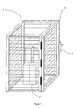
- FIG 1 shows a perspective view of an enclosure 1 that encloses electrically operated machinery 2. Access to the enclosure 1 is gained via a gate 3, which is provided with a safety switch 4. To open the gate 3, the safety switch 4 must be activated. By activating the safety switch 4, the supply of electrical power to the machinery 2 is interrupted, so that when the user is in the enclosure 1, there is little or no danger of the user being injured by the machinery 2. Electrical power to the machinery 2 can only be re-established by the user leaving the enclosure 1 and re-setting the safety switch 4.
- opening the gate 3 may automatically cut the power supply, negating the need to consciously activate the switch 4.
- the gate 3 may only be opened, and the power to the machinery 2 cut off, when an actuator (e.g. a key) is inserted into the safety switch 4.
- the safety switch 4 could even comprise a light gate, whereby when a beam of light is broken the power to the machinery 2 is cut-off.
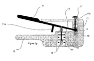
- FIG. 2a illustrates a safety switch in accordance with an embodiment of the present invention.
- the safety switch comprises a casing 10, in which is pivotally mounted a handle 11.
- the handle 11 is free to pivot about a moveable pivot point 12.
- the handle 11 is connected to a set of contacts 13a, 13b by way of a post 14.
- Figure 2a shows the handle 11 with no force applied by a user (not shown), i.e. the handle 11 is in a first operating zone. While in the first operating zone, the pivot point 12 is maintained in position by a biasing member 15. Springs 16 located about the post 14 and contacts 13a, 13b keep the handle 11 in the first operating zone when no force is applied by the user, whereby the contacts 13a, 13b are kept open so that no electrical power can flow through the switch.
- the handle 11 is provided with a fulcrum 11 a which extends perpendicular to the length of the handle 11.
- the safety switch is also provided with a reset actuator 17, which is biased by a spring 17a, and a further spring 18, the significances of which are described in more detail later.
- the safety switch may be formed using any suitable materials.
- the handle 11 I and casing 10 of the safety switch can be formed from a durable plastic, or any material that can electrically insulate the contacts 13a, 13b from the user so that the chances of electrocution are minimised or eliminated.
- the safety switch of the present invention differs from those of the prior art in that the pivot point 12 of the safety switch of the present invention is moveable, and that the safety switch of the present invention is provided with a reset actuator 17.
- the contacts 13a, 13b may be connected between a power supply and equipment to be powered by the power supply (not shown in the figures).
- the safety switch itself may be carried around by the user while in an enclosure.
- Figure 2b illustrates the safety switch when the handle 11 has been depressed to such an extent as to close the electrical contacts 13a and 13b such that electrical power may be supplied to the machinery.
- the handle 11 When the handle 11 is in this position, it is in a second operating zone, i.e. the safety switch is able to conduct electricity.
- the pivot point 12 has not changed position, and that it is still held in position by the biasing member 15.
- the fulcrum 11 a makes contact with a surface of the casing 10 when the handle 11 is in the second operating zone.
- the handle 11 If the user reduces the pressure applied to the handle 11 (for example, by dropping the safety switch), the handle 11 will be pushed from the second operating zone to the first operating zone by the springs 16. At the same time, the electrical contacts 13a, 13b are opened such that the supply of electrical power to the machinery is interrupted. Thus, if the user of the safety switch loses grip on the handle 11 (for example due to an incident involving the machinery), power to the machinery will be cut-off so that the chance of injury to the user is reduced.
- the user of the safety switch losing grip of or dropping the safety switch 11, it is possible that due to a reaction to a dangerous situation the user may actually increase his/her grip on the safety switch and handle 11. If the pressure on the handle 11 exceeds a predetermined amount, it is desirable that power to the machinery is cut off. For example, if the user is startled, it may be safer to cut off power to the machinery than to have a startled user in close proximity to dangerous machinery in operation. This safety measure is particularly important if the user is electrocuted, because a sudden increase in grip is associated with electrocution. If the machinery on which the user is operating causes the user to be electrocuted, the user's grip on the safety switch will increase and cut-off the supply of electricity to the machinery.
- Figure 2c illustrates the handle 11 in a third operating zone, whereby the pressure applied to the handle 11 is greater than that illustrated in figure 2b. It can be seen that since the fulcrum 11a is now in contact with an inner surface of the casing 10, the handle 11 now pivots about the fulcrum 11 a. It can be seen that the pivot point 12 about which the handle 11 pivots in figures 2a and 2b (i.e. when the handle 11 is in the first or second operating zone) has now moved, since the force applied to the handle 11 has caused the pivot point 12 to overcome the biasing member 15. In overcoming the biasing member 15, the pivot point 12 has moved from a first position to a second position. As the pivot point 12 has moved, so has the post 14 which is connected to the contacts 13a, 13b. Consequently, the contacts 13a, 13b are opened. The pivot point 12 is kept in the second position by the further spring 18.
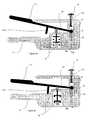
- Figure 2f corresponds to figure 2d, and illustrates that after the handle has been moved to the third operating zone, so that the pivot point 12 moves and the electrical contacts 13a and 13b are opened, electrical power cannot be supplied to the machinery simply by moving the handle 11.
- the contacts 13a, 13b can only be closed, and electrical power restored to the machinery by activation of the reset actuator 17, which will move the pivot point 12 back to its original position.
- Figure 2g shows that in order to reset the safety switch, the reset actuator 17 is depressed.
- the reset actuator 17 pushes the pivot point 12 against the further spring 18, and moves the pivot point 12 from the pivot point's second position to the pivot point's first (and initial) position.
- the spring 17a pushes the reset actuator 17 away from the casing 10 such that the safety switch is returned to its initial settings as illustrated in figure 2a. Electrical power can now be re-supplied to the machinery by depressing the handle 11 to the position as shown and described with reference to figure 2b.
- Provision of the reset actuator 17 ensures that if the user is startled or electrocuted (for example), thereby increasing the pressure on the handle 11, power to the machinery cannot be restored without a deliberate action. This provides an additional safety measure, beyond the non-conducting state of the safety switch when the handle 11 is in the first or third operating zone.
- the handle 11 and casing 10 may be of any suitable shape.
- the handle 11 and casing 10 may be of a certain ergonomic design.
- the handle 11 may not be mounted within the casing 11, but may be attached to any suitable body.
- Pressure applied to the handle 11 need not be applied by the hands of a user.
- the handle 11 may be operated by the foot or feet of a user, or even by the mouth or chin of a user. Such a method of operation leaves both hands of the user free to use tools, equipment etc..
- the safety switch may be used with a power supply and machinery or equipment powered by that power supply.
- the safety switch of the present invention may also be used in conjunction with other safety switches which may be used to control the power supplied to machinery within an enclosure as described above, so that a user may enter an enclosure and operate on machinery safely.
- the springs and biasing members referred to above may be coil springs, leave springs or any suitable biasing element.
- any electrical circuit components may be used to implement the desired supply of electrical power to the machinery.
- the circuit components may be, for example, electrical contacts, a variable resistor, etc.
- the electrical contacts may be arranged to open to prevent the switch from conducting electricity, and arranged to close to allow the switch to conduct electricity.
- the electrical power to the machinery is switched off immediately, i.e. a simple on-off arrangement is employed.
- a simple on-off arrangement ensures that should the user be startled and depress the handle to the third operating zone, the power supply to the machinery is cut-off immediately (as opposed to gradually), so that the time over which the startled user is exposed to operating machinery is minimised.
- the handle need not be pivotably attached to the body.
- the handle may be slidably mounted within the body, and moveable between the first, second and third operating zones.
- the handle may be attached to the body in any suitable manner.
Landscapes
- Switch Cases, Indication, And Locking (AREA)
Abstract
Description
- The present invention relates to a safety switch.
- In a variety of environments, including for example industrial environments, there is a need for systems that are capable of preventing access to one or more pieces of equipment or machinery whilst that equipment or machinery is operating, in a manner that is highly reliable. In some circumstances, this may be achieved by the use of a safety switch.
- Electrically operated machinery, for example, may be located within an enclosure. The enclosure may be a room, a cage, a specific area etc. When a person enters the enclosure, for example by opening a gate, the safety switch disconnects, grounds or otherwise isolates the electrical machinery from one or more power sources in a predictable, reliable manner. Thus, when a user enters the enclosure the chances of him/her suffering injury from the machinery are reduced or eliminated. In some circumstances, the machinery is not able to be restarted until the user has left the enclosure and reset the safety switch. While this is a useful safety feature, it is not very flexible.
- In some circumstances it is conceivable that the user, while inside the enclosure, may still require the machinery to be operating in, for example a special mode (e.g. low speed or incremental movement mode), or, at the very least have control over its operation. For example, the user may wish to have electrical power maintained to the machinery within the enclosure so that he may test the equipment or clean the equipment. If the equipment within the enclosure is of a robotic nature, the user may wish to maintain power to the equipment so that he may teach the robot what to do. In this case, the robot must have some power to learn.
- With prior art safety switches and enclosures, power is in general not supplied to the equipment while a user is in the enclosure. However, safety switches are known which do allow the supply of electrical power to machinery when in the enclosure. The safety switch is connected to the machinery and operable from within the enclosure. An example of such a safety switch has a handle moveable to three positions. In the first position, where no pressure is applied to the handle, the switch does not conduct electricity and no power is supplied to the machinery. When a certain amount of pressure is applied to the handle, electrical contacts within the switch are closed and the switch conducts electricity so that power is supplied to the machinery. If the handle is depressed further, for example due to the user reacting to a dangerous situation, the supply of electrical power to the machinery is cut-off and is not restored until the handle is moved to the second position.
- Thus, it is an object of the present invention to provide a novel safety switch.
- According to a first aspect of the present invention there is provided a safety switch comprising: a body; at least one electrical component for controlling the conduction of electricity by the safety switch; and a handle pivotably attached to the body and pivotable about a pivot point, the handle being pivotable between a first operating zone, a second operating zone and a third operating zone, wherein: the first operating zone corresponds to a situation where the handle is not depressed and the electrical component is arranged such that the safety switch cannot conduct electricity; the second operating zone corresponds to a situation where the handle is depressed to a first extent and the electrical component is arranged such that the safety switch is able to conduct electricity; and the third operating zone corresponds to the situation where the handle is depressed to a further, second extent, and the electrical component is arranged such that the safety switch cannot conduct electricity, wherein the pivot point is moveable from a first position to a second position when the handle is depressed to the third operating zone, the second position of the pivot point being arranged such that the electrical component is arranged such that the safety switch cannot conduct electricity, irrespective of whether the handle is subsequently moved to the first or second operating zones.
- According to a second aspect of the present invention there is provided a powered piece of equipment and a safety switch arranged to allow the control of the supply of power to the equipment, the safety switch comprising: a body; at least one electrical component for controlling the conduction of electricity by the safety switch ; and a handle pivotably attached to the body and pivotable about a pivot point, the handle being pivotable between a first operating zone, a second operating zone and a third operating zone, wherein: the first operating zone corresponds to a situation where the handle is not depressed and the electrical component is arranged, such that the safety switch cannot conduct electricity; the second operating zone corresponds to a situation where the handle is depressed to a first extent and the electrical component is arranged such that the safety switch is able to conduct electricity; and the third operating zone corresponds to the situation where the handle is depressed to a further, second extent, and the electrical component is arranged such that the safety switch cannot conduct electricity, wherein the pivot point is moveable from a first position to a second position when the handle is depressed to the third operating zone, the second position of the pivot point being arranged such that the electrical component is arranged such that the safety switch cannot conduct electricity, irrespective of whether the handle is subsequently moved to the first or second operating zones.
- According to a third aspect of the present invention, there is provided a safety switch comprising: a body; at least one electrical component for controlling the conduction of electricity by the safety switch; and a handle attached to the body, the handle being moveable between a first operating zone, a second operating zone and a third operating zone, wherein: the first operating zone corresponds to a situation where the handle is not depressed and the electrical component is arranged such that the safety switch cannot conduct electricity; the second operating zone corresponds to a situation where the handle is depressed to a first extent and the electrical component is arranged such that the safety switch is able to conduct electricity; and the third operating zone corresponds to the situation where the handle is depressed to a further, second extent, and the electrical component is arranged such that the safety switch cannot conduct electricity, wherein the safety switch further comprises a reset actuator which is arranged such that upon moving the handle to the third operating zone, the electrical component is maintained in an arrangement such that the safety switch cannot conduct electricity, until the reset actuator has been activated.
- The safety switch has the advantage that it avoids power accidentally being provided to machinery by a user unintentionally moving the handle to the second operating zone (for example if the user relaxes his or her grip on the safety switch) after reacting to a dangerous situation and moving the handle to the third operating zone (for example if the user is startled).
- Embodiments of the present invention will now be described, by way of example only, with reference to the accompanying figures, in which:
- Figure 1 is a schematic representation of an enclosure;
- Figures 2a to 2g depict a safety switch according to an embodiment of the present invention.
- Figure 1 shows a perspective view of an
enclosure 1 that encloses electrically operatedmachinery 2. Access to theenclosure 1 is gained via agate 3, which is provided with asafety switch 4. To open thegate 3, thesafety switch 4 must be activated. By activating thesafety switch 4, the supply of electrical power to themachinery 2 is interrupted, so that when the user is in theenclosure 1, there is little or no danger of the user being injured by themachinery 2. Electrical power to themachinery 2 can only be re-established by the user leaving theenclosure 1 and re-setting thesafety switch 4. - It will be appreciated that different safety switches, or different operating principles for a given safety switch may be used. For example, opening the
gate 3 may automatically cut the power supply, negating the need to consciously activate theswitch 4. Alternatively, thegate 3 may only be opened, and the power to themachinery 2 cut off, when an actuator (e.g. a key) is inserted into thesafety switch 4. Thesafety switch 4 could even comprise a light gate, whereby when a beam of light is broken the power to themachinery 2 is cut-off. - It may be desirable to supply power to the
machinery 2 even when the user is in theenclosure 1. However, if a simple on-off switch is provided, the safety measures provided by thesafety switch 4 are circumvented, which re-introduces the possibility of the user suffering injury from themachinery 2. - Figure 2a illustrates a safety switch in accordance with an embodiment of the present invention. The safety switch comprises a
casing 10, in which is pivotally mounted ahandle 11. Thehandle 11 is free to pivot about amoveable pivot point 12. Thehandle 11 is connected to a set ofcontacts post 14. - Figure 2a shows the
handle 11 with no force applied by a user (not shown), i.e. thehandle 11 is in a first operating zone. While in the first operating zone, thepivot point 12 is maintained in position by abiasing member 15. Springs 16 located about thepost 14 andcontacts handle 11 in the first operating zone when no force is applied by the user, whereby thecontacts handle 11 is provided with afulcrum 11 a which extends perpendicular to the length of thehandle 11. The safety switch is also provided with areset actuator 17, which is biased by aspring 17a, and afurther spring 18, the significances of which are described in more detail later. - The safety switch may be formed using any suitable materials. For example, the handle 11 I and
casing 10 of the safety switch can be formed from a durable plastic, or any material that can electrically insulate thecontacts - The safety switch of the present invention differs from those of the prior art in that the
pivot point 12 of the safety switch of the present invention is moveable, and that the safety switch of the present invention is provided with areset actuator 17. - In use, the
contacts - Figure 2b illustrates the safety switch when the
handle 11 has been depressed to such an extent as to close theelectrical contacts handle 11 is in this position, it is in a second operating zone, i.e. the safety switch is able to conduct electricity. It can be seen that thepivot point 12 has not changed position, and that it is still held in position by thebiasing member 15. Thefulcrum 11 a makes contact with a surface of thecasing 10 when thehandle 11 is in the second operating zone. - If the user reduces the pressure applied to the handle 11 (for example, by dropping the safety switch), the
handle 11 will be pushed from the second operating zone to the first operating zone by thesprings 16. At the same time, theelectrical contacts - Instead of the user of the safety switch losing grip of or dropping the
safety switch 11, it is possible that due to a reaction to a dangerous situation the user may actually increase his/her grip on the safety switch and handle 11. If the pressure on thehandle 11 exceeds a predetermined amount, it is desirable that power to the machinery is cut off. For example, if the user is startled, it may be safer to cut off power to the machinery than to have a startled user in close proximity to dangerous machinery in operation. This safety measure is particularly important if the user is electrocuted, because a sudden increase in grip is associated with electrocution. If the machinery on which the user is operating causes the user to be electrocuted, the user's grip on the safety switch will increase and cut-off the supply of electricity to the machinery. - Figure 2c illustrates the
handle 11 in a third operating zone, whereby the pressure applied to thehandle 11 is greater than that illustrated in figure 2b. It can be seen that since thefulcrum 11a is now in contact with an inner surface of thecasing 10, thehandle 11 now pivots about the fulcrum 11 a. It can be seen that thepivot point 12 about which thehandle 11 pivots in figures 2a and 2b (i.e. when thehandle 11 is in the first or second operating zone) has now moved, since the force applied to thehandle 11 has caused thepivot point 12 to overcome the biasingmember 15. In overcoming the biasingmember 15, thepivot point 12 has moved from a first position to a second position. As thepivot point 12 has moved, so has thepost 14 which is connected to thecontacts contacts pivot point 12 is kept in the second position by thefurther spring 18. - It can be seen from figure 2d that when the
handle 11 is released and returned to the first operating zone by thesprings 16, theelectrical contacts electrical contacts handle 11 is depressed until thefulcrum 11a once again comes into contact with the surface of thecasing 10, as illustrated in figure 2e. - Figure 2f corresponds to figure 2d, and illustrates that after the handle has been moved to the third operating zone, so that the
pivot point 12 moves and theelectrical contacts handle 11. Thecontacts reset actuator 17, which will move thepivot point 12 back to its original position. - Figure 2g shows that in order to reset the safety switch, the
reset actuator 17 is depressed. Thereset actuator 17 pushes thepivot point 12 against thefurther spring 18, and moves thepivot point 12 from the pivot point's second position to the pivot point's first (and initial) position. When pressure is removed from thereset actuator 17 thespring 17a pushes thereset actuator 17 away from thecasing 10 such that the safety switch is returned to its initial settings as illustrated in figure 2a. Electrical power can now be re-supplied to the machinery by depressing thehandle 11 to the position as shown and described with reference to figure 2b. - Provision of the
reset actuator 17 ensures that if the user is startled or electrocuted (for example), thereby increasing the pressure on thehandle 11, power to the machinery cannot be restored without a deliberate action. This provides an additional safety measure, beyond the non-conducting state of the safety switch when thehandle 11 is in the first or third operating zone. - It will be appreciated that the
handle 11 andcasing 10 may be of any suitable shape. For example, thehandle 11 andcasing 10 may be of a certain ergonomic design. Thehandle 11 may not be mounted within thecasing 11, but may be attached to any suitable body. - Pressure applied to the
handle 11 need not be applied by the hands of a user. For example, thehandle 11 may be operated by the foot or feet of a user, or even by the mouth or chin of a user. Such a method of operation leaves both hands of the user free to use tools, equipment etc.. - The safety switch may be used with a power supply and machinery or equipment powered by that power supply. The safety switch of the present invention may also be used in conjunction with other safety switches which may be used to control the power supplied to machinery within an enclosure as described above, so that a user may enter an enclosure and operate on machinery safely.
- The springs and biasing members referred to above may be coil springs, leave springs or any suitable biasing element.
- It will be appreciated that the above embodiment has been described by way of example only, and that the various modifications may be made thereto without departing from the invention as defined by the claims, which follow.
- The use of electrical contacts is not essential. In some circumstances a variable power supply (as opposed to a simple on-off arrangement) may be desirable. Movement of the handle between the first operating zone and the second operating zone may be used to control a variable power supply to the machinery, for example to control the speed of operation of the machinery. In this case, movement of the handle may be used to control the resistance of a variable resistor, or any other apparatus suitable for varying the supply of electrical power to the machinery. In short, any electrical circuit components may be used to implement the desired supply of electrical power to the machinery. The circuit components may be, for example, electrical contacts, a variable resistor, etc. The electrical contacts may be arranged to open to prevent the switch from conducting electricity, and arranged to close to allow the switch to conduct electricity.
- Most preferably, when the handle is moved from the second operating zone to the third operating zone, the electrical power to the machinery is switched off immediately, i.e. a simple on-off arrangement is employed. Such an arrangement ensures that should the user be startled and depress the handle to the third operating zone, the power supply to the machinery is cut-off immediately (as opposed to gradually), so that the time over which the startled user is exposed to operating machinery is minimised.
- It will be appreciated that the handle need not be pivotably attached to the body. For example, the handle may be slidably mounted within the body, and moveable between the first, second and third operating zones. In the case where pivotable attachment of the handle to the body is not essential, the handle may be attached to the body in any suitable manner.
Claims (13)
- A safety switch comprising:a body;at least one electrical component for controlling the conduction of electricity by the safety switch; anda handle pivotably attached to the body and pivotable about a pivot point, the handle being pivotable between a first operating zone, a second operating zone and a third operating zone, wherein:the first operating zone corresponds to a situation where the handle is not depressed and the electrical component is arranged such that the safety switch cannot conduct electricity;the second operating zone corresponds to a situation where the handle is depressed to a first extent and the electrical component is arranged such that the safety switch is able to conduct electricity; andthe third operating zone corresponds to the situation where the handle is depressed to a further, second extent, and the electrical component is arranged such that the safety switch cannot conduct electricity,wherein the pivot point is moveable from a first position to a second position when the handle is depressed to the third operating zone, the second position of the pivot point being arranged such that the electrical component is arranged such that the safety switch cannot conduct electricity, irrespective of whether the handle is subsequently moved to the first or second operating zones.
- A safety switch as claimed in claim 1, further comprising a reset actuator which is arranged such that upon moving the handle to the third operating zone, the electrical component is maintained in an arrangement such that the safety switch cannot conduct electricity, until the reset actuator has been activated.
- A safety switch as claimed in claim 2, wherein the reset actuator is arranged to move the moveable pivot point from the second position to the first position.
- A safety switch as claimed in any preceding claim, wherein when the moveable pivot point is in the first pivot point position, the moveable pivot point is maintained in position by a first biasing member.
- A safety switch as claimed in any preceding claim, wherein when the moveable pivot point is in the second position, the moveable pivot point is maintained in position by a second biasing member.
- A safety switch as claimed in any preceding claim, wherein the handle is provided with a fulcrum, and wherein upon moving the handle between the second operating zone and the third operating zone, the handle is arranged to pivot about the fulcrum such that the moveable pivot point of the handle is made to move from the first position to the second position.
- A powered piece of equipment and a safety switch arranged to allow the control of the supply of power to the equipment, the safety switch comprising:a body;at least one electrical component for controlling the conduction of electricity by the safety switch; anda handle pivotably attached to the body and pivotable about a pivot point, the handle being pivotable between a first operating zone, a second operating zone and a third operating zone, wherein:the first operating zone corresponds to a situation where the handle is not depressed and the electrical component is arranged, such that the safety switch cannot conduct electricity;the second operating zone corresponds to a situation where the handle is depressed to a first extent and the electrical component is arranged such that the safety switch is able to conduct electricity; andthe third operating zone corresponds to the situation where the handle is depressed to a further, second extent, and the electrical component is arranged such that the safety switch cannot conduct electricity,wherein the pivot point is moveable from a first position to a second position when the handle is depressed to the third operating zone, the second position of the pivot point being arranged such that the electrical component is arranged such that the safety switch cannot conduct electricity, irrespective of whether the handle is subsequently moved to the first or second operating zones.
- A powered piece of equipment and a safety switch as claimed in claim 7, further comprising a reset actuator arranged such that upon moving the handle to the third operating zone, the electrical component is maintained in an arrangement such that the safety switch cannot conduct electricity, until the reset actuator has been activated.
- A powered piece of equipment and a safety switch as claimed in claim 7 or claim 8, wherein the safety switch is arranged to allow the control of the supply of electrical power to the equipment.
- A safety switch comprising:a body;at least one electrical component for controlling the conduction of electricity by the safety switch; anda handle attached to the body, the handle being moveable between a first operating zone, a second operating zone and a third operating zone, wherein:the first operating zone corresponds to a situation where the handle is not depressed and the electrical component is arranged such that the safety switch cannot conduct electricity;the second operating zone corresponds to a situation where the handle is depressed to a first extent and the electrical component is arranged such that the safety switch is able to conduct electricity; andthe third operating zone corresponds to the situation where the handle is depressed to a further, second extent, and the electrical component is arranged such that the safety switch cannot conduct electricity,wherein the safety switch further comprises a reset actuator which is arranged such that upon moving the handle to the third operating zone, the electrical component is maintained in an arrangement such that the safety switch cannot conduct electricity, until the reset actuator has been activated.
- A safety switch as claimed in claim 11, wherein the handle is pivotably attached to the body and pivotable about a pivot point.
- A safety switch as claimed in claim 11, wherein the pivot point is moveable from a first position to a second position when the handle is depressed to the third operating zone, the second position of the pivot point being arranged such that the electrical component is arranged such that the safety switch cannot conduct electricity, irrespective of whether the handle is subsequently moved to the first or second operating zones.
- A safety switch as claimed in claim 12, wherein the reset actuator is arranged to move the moveable pivot point from the second position to the first position.
Applications Claiming Priority (1)
| Application Number | Priority Date | Filing Date | Title |
|---|---|---|---|
| GBGB0606154.3A GB0606154D0 (en) | 2006-03-28 | 2006-03-28 | Safety switch |
Publications (3)
| Publication Number | Publication Date |
|---|---|
| EP1840918A2 true EP1840918A2 (en) | 2007-10-03 |
| EP1840918A3 EP1840918A3 (en) | 2009-01-21 |
| EP1840918B1 EP1840918B1 (en) | 2012-05-16 |
Family
ID=36424690
Family Applications (1)
| Application Number | Title | Priority Date | Filing Date |
|---|---|---|---|
| EP07251230A Ceased EP1840918B1 (en) | 2006-03-28 | 2007-03-22 | Safety switch |
Country Status (3)
| Country | Link |
|---|---|
| US (1) | US7777146B2 (en) |
| EP (1) | EP1840918B1 (en) |
| GB (1) | GB0606154D0 (en) |
Cited By (1)
| Publication number | Priority date | Publication date | Assignee | Title |
|---|---|---|---|---|
| EP4513520A1 (en) * | 2023-08-22 | 2025-02-26 | Black & Decker, Inc. | Switch activation mechanism |
Families Citing this family (1)
| Publication number | Priority date | Publication date | Assignee | Title |
|---|---|---|---|---|
| DE202014001722U1 (en) * | 2014-02-27 | 2014-07-03 | André Haake | Switching arrangement on a mobile device and industrial truck with such a switching arrangement |
Family Cites Families (6)
| Publication number | Priority date | Publication date | Assignee | Title |
|---|---|---|---|---|
| US2947840A (en) * | 1958-04-25 | 1960-08-02 | Cutler Hammer Inc | Electric switch |
| US4376877A (en) * | 1981-07-10 | 1983-03-15 | Decker Melvin H | Multiposition switch |
| DE8812349U1 (en) | 1988-09-29 | 1989-07-27 | Siemens AG, 1000 Berlin und 8000 München | Three-layer handle |
| DE19615682C2 (en) | 1996-04-22 | 2001-04-26 | H J Bernstein Gmbh Unternehmen | Safety switch |
| JPH10291189A (en) | 1997-04-21 | 1998-11-04 | Fanuc Ltd | Robot emergency stop switch mechanism and teaching operation panel provided with the mechanism |
| WO2002061779A1 (en) | 2001-02-01 | 2002-08-08 | Idec Izumi Corporation | Enable switch |
-
2006
- 2006-03-28 GB GBGB0606154.3A patent/GB0606154D0/en not_active Ceased
-
2007
- 2007-03-09 US US11/684,325 patent/US7777146B2/en active Active
- 2007-03-22 EP EP07251230A patent/EP1840918B1/en not_active Ceased
Cited By (1)
| Publication number | Priority date | Publication date | Assignee | Title |
|---|---|---|---|---|
| EP4513520A1 (en) * | 2023-08-22 | 2025-02-26 | Black & Decker, Inc. | Switch activation mechanism |
Also Published As
| Publication number | Publication date |
|---|---|
| EP1840918B1 (en) | 2012-05-16 |
| US7777146B2 (en) | 2010-08-17 |
| EP1840918A3 (en) | 2009-01-21 |
| US20070227869A1 (en) | 2007-10-04 |
| GB0606154D0 (en) | 2006-05-10 |
Similar Documents
| Publication | Publication Date | Title |
|---|---|---|
| CN106955157B (en) | Electrosurgical device | |
| US6482200B2 (en) | Cautery apparatus and method | |
| EP1714617B1 (en) | Footswitch operable to control a surgical system | |
| JP7177834B2 (en) | Automatic emergency stop electric cutting tool | |
| CN2798684Y (en) | Blower possessing facile controlling switch | |
| CN106514568B (en) | Method for starting a hand-guided work apparatus having an electric motor | |
| MX2007007841A (en) | Multifunction surgical probe. | |
| WO1990001786A1 (en) | Lock-on/lock-off switch for power tool | |
| EP3054825B2 (en) | Kitchen appliances with speed control | |
| CN106457547B (en) | Throttle lockout with different actions | |
| JP2009515308A (en) | Electric hand controller, especially for electrically adjustable hospital and nursing beds | |
| EP3141357B1 (en) | Electric scissors | |
| EP1840918B1 (en) | Safety switch | |
| GB2513326A (en) | Electrosurgical instrument | |
| GB0318751D0 (en) | Safety mechanism for power tool and power tool incorporating such mechanism | |
| WO2005046372A3 (en) | Switching device for flexible material | |
| EP2571037B1 (en) | Electric motor-driven kitchen appliance | |
| TWI286772B (en) | Ambidextrous switch lockout system | |
| EP2365502B1 (en) | Power tools and switching apparatus therefor | |
| CN104647310B (en) | Switch device for electrically driven garden tool | |
| US8288670B2 (en) | Electric deadman switch for blast system | |
| US20250099162A1 (en) | Caiman ring forceps - manual hf activation | |
| US4857681A (en) | Dead man-type electrical control device for power tools | |
| RU2815109C2 (en) | Hand held motor unit of electrical household appliance | |
| SE458183B (en) | Retainer for connection of robot |
Legal Events
| Date | Code | Title | Description |
|---|---|---|---|
| PUAI | Public reference made under article 153(3) epc to a published international application that has entered the european phase |
Free format text: ORIGINAL CODE: 0009012 |
|
| AK | Designated contracting states |
Kind code of ref document: A2 Designated state(s): AT BE BG CH CY CZ DE DK EE ES FI FR GB GR HU IE IS IT LI LT LU LV MC MT NL PL PT RO SE SI SK TR |
|
| AX | Request for extension of the european patent |
Extension state: AL BA HR MK YU |
|
| PUAL | Search report despatched |
Free format text: ORIGINAL CODE: 0009013 |
|
| AK | Designated contracting states |
Kind code of ref document: A3 Designated state(s): AT BE BG CH CY CZ DE DK EE ES FI FR GB GR HU IE IS IT LI LT LU LV MC MT NL PL PT RO SE SI SK TR |
|
| AX | Request for extension of the european patent |
Extension state: AL BA HR MK RS |
|
| RAP1 | Party data changed (applicant data changed or rights of an application transferred) |
Owner name: ROCKWELL AUTOMATION LIMITED |
|
| AKX | Designation fees paid | ||
| 17P | Request for examination filed |
Effective date: 20090617 |
|
| RBV | Designated contracting states (corrected) |
Designated state(s): DE FR GB |
|
| REG | Reference to a national code |
Ref country code: DE Ref legal event code: 8566 |
|
| 17Q | First examination report despatched |
Effective date: 20091029 |
|
| GRAP | Despatch of communication of intention to grant a patent |
Free format text: ORIGINAL CODE: EPIDOSNIGR1 |
|
| RAP1 | Party data changed (applicant data changed or rights of an application transferred) |
Owner name: FT TECHNOLOGY LIMITED |
|
| GRAS | Grant fee paid |
Free format text: ORIGINAL CODE: EPIDOSNIGR3 |
|
| RAP1 | Party data changed (applicant data changed or rights of an application transferred) |
Owner name: ROCKWELL AUTOMATION LIMITED |
|
| GRAA | (expected) grant |
Free format text: ORIGINAL CODE: 0009210 |
|
| AK | Designated contracting states |
Kind code of ref document: B1 Designated state(s): DE FR GB |
|
| REG | Reference to a national code |
Ref country code: GB Ref legal event code: FG4D |
|
| REG | Reference to a national code |
Ref country code: DE Ref legal event code: R096 Ref document number: 602007022623 Country of ref document: DE Effective date: 20120726 |
|
| PLBE | No opposition filed within time limit |
Free format text: ORIGINAL CODE: 0009261 |
|
| STAA | Information on the status of an ep patent application or granted ep patent |
Free format text: STATUS: NO OPPOSITION FILED WITHIN TIME LIMIT |
|
| 26N | No opposition filed |
Effective date: 20130219 |
|
| REG | Reference to a national code |
Ref country code: DE Ref legal event code: R097 Ref document number: 602007022623 Country of ref document: DE Effective date: 20130219 |
|
| REG | Reference to a national code |
Ref country code: FR Ref legal event code: PLFP Year of fee payment: 10 |
|
| REG | Reference to a national code |
Ref country code: FR Ref legal event code: PLFP Year of fee payment: 11 |
|
| REG | Reference to a national code |
Ref country code: FR Ref legal event code: PLFP Year of fee payment: 12 |
|
| PGFP | Annual fee paid to national office [announced via postgrant information from national office to epo] |
Ref country code: DE Payment date: 20200218 Year of fee payment: 14 Ref country code: GB Payment date: 20200224 Year of fee payment: 14 |
|
| PGFP | Annual fee paid to national office [announced via postgrant information from national office to epo] |
Ref country code: FR Payment date: 20200220 Year of fee payment: 14 |
|
| REG | Reference to a national code |
Ref country code: DE Ref legal event code: R119 Ref document number: 602007022623 Country of ref document: DE |
|
| GBPC | Gb: european patent ceased through non-payment of renewal fee |
Effective date: 20210322 |
|
| PG25 | Lapsed in a contracting state [announced via postgrant information from national office to epo] |
Ref country code: DE Free format text: LAPSE BECAUSE OF NON-PAYMENT OF DUE FEES Effective date: 20211001 Ref country code: GB Free format text: LAPSE BECAUSE OF NON-PAYMENT OF DUE FEES Effective date: 20210322 Ref country code: FR Free format text: LAPSE BECAUSE OF NON-PAYMENT OF DUE FEES Effective date: 20210331 |