EP1840546B1 - Torque detecting apparatus, and method for assembling torque detecting apparatus - Google Patents
Torque detecting apparatus, and method for assembling torque detecting apparatus Download PDFInfo
- Publication number
- EP1840546B1 EP1840546B1 EP07105051.2A EP07105051A EP1840546B1 EP 1840546 B1 EP1840546 B1 EP 1840546B1 EP 07105051 A EP07105051 A EP 07105051A EP 1840546 B1 EP1840546 B1 EP 1840546B1
- Authority
- EP
- European Patent Office
- Prior art keywords
- shaft
- rotating
- axial direction
- face
- cylindrical magnet
- Prior art date
- Legal status (The legal status is an assumption and is not a legal conclusion. Google has not performed a legal analysis and makes no representation as to the accuracy of the status listed.)
- Expired - Fee Related
Links
Images


Classifications
-
- G—PHYSICS
- G01—MEASURING; TESTING
- G01L—MEASURING FORCE, STRESS, TORQUE, WORK, MECHANICAL POWER, MECHANICAL EFFICIENCY, OR FLUID PRESSURE
- G01L3/00—Measuring torque, work, mechanical power, or mechanical efficiency, in general
- G01L3/02—Rotary-transmission dynamometers
- G01L3/04—Rotary-transmission dynamometers wherein the torque-transmitting element comprises a torsionally-flexible shaft
- G01L3/10—Rotary-transmission dynamometers wherein the torque-transmitting element comprises a torsionally-flexible shaft involving electric or magnetic means for indicating
- G01L3/101—Rotary-transmission dynamometers wherein the torque-transmitting element comprises a torsionally-flexible shaft involving electric or magnetic means for indicating involving magnetic or electromagnetic means
- G01L3/104—Rotary-transmission dynamometers wherein the torque-transmitting element comprises a torsionally-flexible shaft involving electric or magnetic means for indicating involving magnetic or electromagnetic means involving permanent magnets
Definitions
- the present invention relates to a torque detecting apparatus for detecting rotational torque applied to a rotating shaft, and also relates to a method for assembling the same.
- An electric power steering apparatus have widely been used for assisting a steering operation by applying driving power of an electric motor to a steering mechanism upon responding to a turning operation of a steering member such as a steering wheel.
- a conventional electric power steering apparatus is provided with a torque detecting apparatus for detecting a steering torque applied to a steering member thus to control driving of the electric motor for assisting the steering.
- Such torque detecting apparatus is configured so that a steering shaft (rotating shaft), for connecting the steering member and the steering mechanism, is divided into two, first and second, shafts, which are coaxially connected to each other by a small diameter torsion bar, and the steering torque (rotational torque) applied to the steering shaft by the operation of the steering member can be detected as a relative angular displacement between the first shaft and the second shaft derived from a twist of the torsion bar.
- torque detecting means for detecting the relative angular displacement between the first shaft and the second shaft has been conventionally proposed in various configurations.
- One example of such prior art is known which is provided with a cylindrical magnet (first rotating member) fixedly fitted to an outer surface of the first shaft and a yoke ring (second rotating member) surrounding an outer circumference of the cylindrical magnet and integrally rotates with the second shaft, and configured so as to detect the relative angular displacement between the first shaft and the second shaft from a change in the magnetic circuit between the cylindrical magnet and the yoke ring (for example, referring to Japanese Patent Application Laid-open No. 2003-149062 ).
- the cylindrical magnet is configured by arranging N poles and S poles alternately in the circumferential direction thereof, and fixedly fitted to the outer surface of the first shaft.
- the yoke ring is configured by a pair of thin rings made of soft magnetic, sized substantially identical to each other, and provided with magnetic pole teeth which are identical in the number to the N and S poles and arranged circumferentially at equal intervals on an end edge of one side of a circular ring body of the yoke ring.
- the two rings are formed integral by a mold body made of a resin formed in a cylindrical shape.
- the two rings are positioned so that the magnetic pole teeth of both rings are alternately arranged in the circumferential direction and each magnetic pole tooth arranged on one ring is positioned at the center between each adjoining magnetic pole teeth arranged on the other ring.
- the mold body is fixedly fitted onto the connecting side end portion of the second shaft by a metallic collar formed integrally with one side end portion thereof.
- the cylindrical magnet and the yoke ring are positioned in the circumferential direction and assembled together so that each of the magnetic pole teeth corresponds to the boundary between the N pole and the S pole of the cylindrical magnet. Accordingly, when a relative angular displacement between the first shaft and the second shaft is caused by the steering shaft being applied the steering torque, the positional relationship between the magnetic pole teeth of the two yoke rings and the magnetic poles of the cylindrical magnet is changed. As the positional relationship is changed, the magnetic flux generated in the two yoke rings changes. A change in the magnetic flux is then detected to determine the magnitude of the steering torque.
- the positioning in the axial direction is carried out by relatively moving the first shaft and the second shaft in the axial direction before the first shaft and the second shaft are connected to each other by the torsion bar. Nevertheless, since the cylindrical magnet and the yoke rings to be positioned are located in the housing which rotatably supports the first shaft and the second shaft, their positional relationship may hardly be acknowledged by view. Thus, conventionally, positioning in the axial direction was taken as below. At first, while the second shaft is positioned and supported in the housing, the first shaft is lowered and inserted until the end portion of the cylindrical magnet fixedly fitted onto the first shaft collides against the second shaft or the yoke rings formed integrally with the second shaft. Then, using the collision position as a reference position, the first shaft is moved back or lifted up in a direction of departing from the second shaft by a predetermined distance.
- the cylindrical magnet fixedly fitted onto the first shaft includes a group of magnetic segments of a rectangular shape which are arranged in the circumferential direction and assembled together with the mold body of a resin in a cylindrical shape.
- the mold body of a resin may be injured thus to have, for example, cracks or flaws by the first shaft colliding against the second shaft for determining the reference position during the positioning operation described above.
- any other conventional torque detecting apparatus in an electric power steering apparatus is similarly arranged for detecting a relative angular displacement between the first shaft and the second shaft connected to each other by the torsion bar with the use of various detecting means.
- any other conventional torque detecting apparatus is adapted for detecting a relative angular displacement between a first rotating member fixedly fitted onto the first shaft and a second rotating member integrally rotating with the second shaft, its relative positioning in the axial direction of the two rotating members will encounter the foregoing drawback.
- US 2005/257992 discloses an electric power steering system including a torque detecting apparatus.
- the present invention has been developed in view of the above circumstances and its object is to provide a torque detecting apparatus in which the positioning in the axial direction of the first and second rotating members integrally rotating with the first shaft and the second shaft, respectively can be conducted surely and easily, and a method for assembling the torque detecting apparatus.
- a method according to the present invention is recited in claim 1.
- An embodiment is recited in claim 2.
- FIG. 1 is an exploded perspective view of a torque detecting apparatus according to the present invention
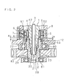
- FIG. 2 is a longitudinally cross sectional view showing an essential portion in the assembled state of the same.
- the torque detecting apparatus intends to detect the torque applied to two shafts (a first shaft and a second shaft) which are connected coaxially to each other by a torsion bar 3.
- the torque detecting apparatus according to the present invention is configured by comprising a cylindrical magnet 4 integrally rotating with the first shaft 1, a pair of yoke rings 5, 5 integrally rotating with the second shaft 2, magnetism collecting rings 6, 6 for collecting magnetic fluxes generated in the yoke rings 5, 5, respectively, and two magnetic sensors 7, 7 disposed between the magnetism collecting rings 6 and 6 as will be described later in more detail.
- the torsion bar 3 is a small-diameter round bar as a torsion spring. At both end portions of the torsion bar 3, connecting portions 30, 30 having large-diameters for respectively connecting the first shaft 1 and the second shaft 2 are formed, respectively.
- the first shaft 1 and the second shaft 2 are integrally connected by fitting the connecting portions 30, 30 at the both end portions of the torsion bar 3 into a connecting bores 10, 20 formed respectively in the axial center portions of the first shaft 1 and the second shaft 2, and by knocking respective connecting pins 11 and 21 after positioning in both the axial direction and the circumferential direction.
- FIG. 2 in an electric power steering apparatus, an example is shown where the torque detecting apparatus according to the present invention is applied as a steering torque detecting means for detecting the steering torque applied to the steering shaft for connecting a steering member and a steering mechanism.
- the first shaft 1 and the second shaft 2 which are respective shaft by dividing the steering shaft at middle are coaxially connected to each other by the torsion bar 3.
- the first shaft 1 at the upper position is connected to the steering member not shown, while the second shaft 2 at the lower position is connected to the steering mechanism not shown.
- the connecting portion of the torsion bar 3 and the second shaft 2 only is shown in FIG. 2 .
- the second shaft 2 at the side of the steering mechanism is supported at two positions by upper and lower two bearings 80 and 81 in a housing 8 which is partially shown in FIG. 2 .
- a worm wheel 82 is fixedly fitted between the two bearings 80 and 81.
- the worm wheel 82 is meshed with a worm (not shown) fixed to the output shaft of an electric motor for assisting steering.
- the electric motor for assisting steering is driven, rotation generated by the electric motor for assisting steering is reduced and transmitted to the worm wheel 82, and a steering assistance force is applied as to the steering mechanism via the second shaft 2.
- the second shaft 2 has a large-diameter connecting cylinder (facing member) 22 connectedly provided above the supporting position of the bearing 80.
- the end portion at the connecting side of the first shaft 1 is inserted by a proper length into a support bore 23 which opens at the end face of the connecting cylinder 22 and continues to the connecting bore 20 of the torsion bar 3.
- the first shaft 1 is supported maintaining coaxially state with the second shaft 2 by a bush 24 tightly fitted into the support bore 23.
- the cylindrical magnet 4 integrally rotating with the first shaft 1, in which a plurality of N poles 40, 40,... and a plurality of S poles 41, 41,... are arranged alternately in the circumferential direction, is covered its end faces and inner face with a mold body 42 made of resin by suitable thickness, and is configured as a multi-pole magnet.
- the cylindrical magnet 4 is fixedly fitted onto the first shaft 1 interposing the mold body 42, and positioned in the axial direction so that the lower end face of the mold body 42 and the upper end face of the connecting cylinder 22 of the second shaft 2 face each other at a predetermined space A, as shown in FIG. 2 .
- a portion of the first shaft 1 onto which the cylindrical magnet 4 is fixedly fitted is formed greater in a diameter than the other portion and is extended across and downwardly from the cylindrical magnet 4.
- a facing surface 12 which faces an upper end face of the connecting cylinder 22 of the second shaft 2 by a space a is formed.
- a facing portion is composed of these connecting cylinder 22 as the facing member and the facing surface 12.
- the space of the facing portion specifically, the space a between the upper end face of the connecting cylinder 22 and the facing surface 12 is set smaller than the space A between the upper end face of the connecting cylinder 22 and the lower end face of the mold body 42, as shown in FIG. 2 .
- the yoke rings 5, 5 integrally rotating with the second shaft 2 are circular rings made of soft magnetic each having a ring-like shape yoke body 50 onto whose inner circumference edge magnetic pole teeth 51, 51,... are arranged at equal intervals along thereof, each tooth extending in the axial direction.
- Each magnetic pole tooth 51 of the yoke ring 5 is formed in a triangular shape which is extended from the base of the yoke body 50 and made to be narrower in the width towards the distal end.
- the magnetic pole teeth 51 are provided as equal to the number of sets of the N poles 40 and S poles 41 of the cylindrical magnet 4.
- the two yoke rings 5, 5 are coaxially arranged in such a manner that their magnetic pole teeth 51 face at the distal end and the each magnetic pole teeth 51 of both yoke rings 5, 5 align alternately in the circumferential direction. Then, the outer sides of the two yoke rings 5, 5 are covered integrally with the mold body 52 of a resin formed in a cylindrical shape by molding.
- the yoke rings 5, 5 configured as described above are fixedly fitted onto the connecting cylinder 22 at the upper end portion of the second shaft 2 through a collar 53 which is made to be integral with the inner circumference of the lower end portion of the mold body 52, as shown in FIG. 2 . It is noted that respective inner surface of the yoke rings 5, 5 is spaced by a small air gap from the outer circumference of the cylindrical magnet 4 fixedly fitted to the first shaft 1 so that the yoke rings 5, 5 are assembled with respect to the cylindrical magnet 4 under a state where a predetermined positional relationship with respect to the cylindrical magnet 4 in the axial direction and circumferential direction can be obtained.
- FIG. 3A, FIG. 3B, and FIG. 3C are explanatory views showing the positional relationship between the magnetic pole teeth of the yoke rings and the magnetic poles of the cylindrical magnet.
- FIG. 3B the relationship between the magnetic pole teeth 51, 51,... of both the yoke rings 5, 5 and each N magnetic pole 40 and each S magnetic pole 41 of the cylindrical magnet 4 in the assembled state is shown.
- the yoke rings 5, 5 and the cylindrical magnet 4 are relatively positioned in the circumferential direction so that the distal end of each of the magnetic pole teeth 51, 51,...
- each magnetic pole teeth 51 of the two yoke rings 5, 5 is positioned in the magnetic field generated between the adjacent N pole 40 and the S pole 41 at the circumference of the cylindrical magnet 4 under the same condition. As the result, the magnetic flux which are generated in the two yoke bodies 50, 50 communicating each proximal ends of the magnetic pole teeth 51 become equal.
- the positional relationship in the circumferential direction between the magnetic pole teeth 51, 51,... and the N poles 40 and S poles 41 changes in such opposite directions as shown in FIG. 3A or FIG. 3C , depending on the relative angular displacement generated, accompanying with a twist of the torsion bar 3, between the first shaft 1 to which the cylindrical magnet 4 is fixed and the second shaft 2 to which the yoke rings 5, 5 are fixed.
- the lines of magnetic force at the opposite polarities increase in the magnetic pole teeth 51, 51,... of one yoke rings 5 and the magnetic pole teeth 51, 51,... of other yoke rings 5, 5, the positive or negative magnetic flux are generated in the respective yoke bodies 50, 50.
- the positive or negative of the magnetic flux is determined by the direction of the relative angular displacement between the cylindrical magnet 4 and the yoke rings 5, 5, that is, between the first shaft 1 and the second shaft 2. Also, the density of the positive or negative magnetic flux is determined by the magnitude of the relative angular displacement between the first shaft 1 and the second shaft 2. Accordingly, when the positive or negative and density of the magnetic flux generated in the yoke bodies 50, 50 is detected, it can be found the relative angular displacement between the first shaft 1 and the second shaft 2, that is, the direction and magnitude of the rotational torque (the steering torque) applied to the first shaft 1 and the second shaft 2.
- the magnetic flux generated in the yoke rings 5, 5 are collected by the magnetism collecting rings 6, 6 and then detected by the magnetic sensors 7, 7.
- the magnetism collecting rings 6, 6 are circular rings made of soft magnetic, and whose inner diameter is slightly greater than the outer diameter of the yoke body 50. As shown in FIG. 1 , each of the magnetism collecting rings 6, 6 has magnetism collecting portions 60, 60 at the two positions corresponding with each other by extending therefrom in the axial direction and then bending their distal ends outwardly at substantially a right angle.
- magnetism collecting rings 6, 6 are arranged coaxially with the extending sides of the magnetism collecting portions 60, 60 opposite to each other at the distal end, and are positioned in the axial direction so that their magnetism collecting portions 60, 60 become opposite to each other at the distal end and separated by a predetermined air gap. Furthermore, as shown in FIG. 2 , the two magnetism collecting rings 6, 6 are formed in a single unit by being covered integrally with a mold body 61 of a resin formed in a cylindrical shape by molding.
- the magnetic sensors 7 composed of a magnetic detecting element such as a Hall device are disposed.
- the mold body 61 holding the magnetism collecting rings 6, 6 and the magnetic sensors 7,7 is fixedly fitted in the housing 8 under the state where the respective magnetism collecting rings 6, 6 exposing to the inner surface are arranged to face at close proximity to the outer surfaces of the corresponding yoke rings 5, 5, as shown in FIG. 2 .
- the magnetic flux generated in the yoke rings 5, 5 to be dissipated thereto is induced and collected to the magnetism collecting portions 60, 60.
- the magnetic sensors 7, 7 generate outputs corresponding to the density of the leaked magnetic flux.
- the density of the magnetic flux detected by the magnetic sensors 7, 7 changes depending on the magnetic flux in the yoke rings 5, 5 opposite to the inner side of the magnetism collecting rings 6, 6. Also as described previously, this magnetic flux changes depending on the relative angular displacement between the first shaft 1 and the second shaft 2. Accordingly, the outputs of the magnetic sensors 7, 7 correspond to the direction and magnitude of the rotational torque applied to the first shaft 1 and the second shaft 2 which generates a relative angular displacement between them and can thus be detected the rotational torque applied to the first shaft 1 and the second shaft 2 based on the output change of these magnetic sensors 7, 7.
- the reason why the two magnetic sensors 7, 7 are provided is that while one is for detecting the torque, while the other is for judging a fail-safe operation.
- the fail-safe operation is carried out by a known procedure such that the outputs of the magnetic sensors 7, 7 are compared with each other in time series and when a significant difference between the two outputs is found, the magnetic sensor 7 whose outputs has been unstable at before and after that time is judged to be fail state.
- the cylindrical magnet 4 and the yoke rings 5, 5 For detecting the rotational torque at higher accuracy, it is necessary for positioning the cylindrical magnet 4 and the yoke rings 5, 5 with correctness in both the axial direction and the circumferential direction.
- the positioning should be made by relatively moving the first shaft 1 to which the cylindrical magnet 4 is fixed and the second shaft 2 to which the yoke rings 5, 5 are fixed before the first shaft 1 and the second shaft 2 are connected to each other by the torsion bar 3.
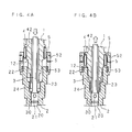
- FIG. 4A and FIG. 4B are explanatory views showing a procedure of the positioning of the cylindrical magnet 4 and the yoke rings 5, 5.
- the second shaft 2 to which the yoke rings 5, 5 are fixed is previously positioned and supported by the two bearings 80 and 81 in the housing 8.
- the front end of the first shaft 1 is moved in the direction close up to the second shaft 2 and inserted into the support bore 23 opened at the end portion of the connecting cylinder 22, as shown in FIG. 4A .
- the torsion bar 3 has been fitted into the connecting bore 20 and connected to the second shaft 2 by the connecting pin 21 while it is not connected to the first shaft 1. Meanwhile, the first shaft 1 is movable in relation to the second shaft 2 in both the axial direction and the circumferential direction.
- FIG. 4A and FIG. 4B it is noted that the housing 8 and the bearings 80 and 81 are not illustrated.
- FIG. 4B illustrates the state where the first shaft 1 coming into direct contact with the second shaft 2.
- the space a between the facing surface 12 and the upper end face of the connecting cylinder 22 is set smaller than the space A between the lower end face of the cylindrical magnet 4 and the upper end face of the connecting cylinder 22. Because such relationship between the two spaces a and A, collision of the first shaft 1 against the second shaft 2 occurs when the facing surface 12 collides against the connecting cylinder 22, as shown in FIG. 4B .
- a - a a predetermined space
- the cylindrical magnet 4 concretely, the resin mold body 42 covering the outer side of the cylindrical magnet 4 collides against the second shaft 2, concretely, the upper end face of the connecting cylinder 22. Accordingly, at the colliding of the first shaft 1 against the second shaft 2 carried out in the housing 8 not viewing, even when the first shaft 1 is made to be collided against the second shaft 2, the mold body 42 of the connected cylindrical magnet 4 is prevented from any physical fault such as cracks or flaws.
- the first shaft 1 is moved back with respect to the second shaft 2 by a distance corresponding to the above mentioned space a (See FIG. 2 ) in the direction departing from the second shaft 2 as denoted by a white arrow in FIG. 4B .
- the positioning of the first shaft 1 with respect to the second shaft 2 in the axial direction is completed.
- the space a between the upper end face of the connecting cylinder 22 of the second shaft 2 and the facing surface 12 of the first shaft 1 is secured, and the space A between the upper end face of the connecting cylinder 22 and the lower end face of the cylindrical magnet 4 is also secured. This means that the cylindrical magnet 4 is correctly aligned and positioned in the axial direction with respect to the yoke rings 5, 5 as shown in FIG. 2 .
- the positioning of the cylindrical magnet 4 and the yoke rings 5, 5 in the circumferential direction is carried out.
- the outputs of the two magnetic sensors 7, 7 disposed between the magnetism collecting rings 6, 6 change as described above. Accordingly, the positioning in the circumferential direction between them can be carried out by procedure such that the first shaft 1 is rotated with respect to the second shaft 2 in the circumferential direction while monitoring the outputs of the magnetic sensors 7, 7.
- a through hole penetrating the first shaft 1 and the upper side connecting portion 30 of the torsion bar 3 is bored for knocking the connecting pin 11. Then, by knocking the connecting pin 11 into the through hole, the other end portion of the torsion bar 3 is connected to the first shaft 1. As the result, the first shaft 1 and the second shaft 2 are integrally connected.
- the cylindrical magnet 4 and the yoke rings 5, 5 are positioned in not only the circumferential direction but also the axial direction, so that torque detection is carried out at higher accuracy.
- the collision of the first shaft 1 and the second shaft 2 necessary for positioning the cylindrical magnet 4 and the yoke rings 5, 5 occurs between the facing surface 12 provided at the first shaft 1 and the connecting cylinder 22 provided at the second shaft 2. Therefore, the resin mold body 42 holding the cylindrical magnet 4 is prevented from being injured.
- the torque detecting apparatus of the present invention will highly be suited for detecting the steering torque applied to the steering member in an electric power steering apparatus as shown in the embodiment.
- the torque detecting apparatus configured such that the cylindrical magnet 4 as the first rotating member fixedly fitted onto the first shaft 1 is provided, and its relative angular displacement with respect to the yoke rings 5, 5 (the second rotating member) integrally rotating with the second shaft 2 is detected. It would however be understood that the present invention is not limited to the torque detecting apparatus of this embodiment but may equally be applied to any other torque detecting apparatus which has a first rotating member and a second rotating member of another configuration and needs to determine the positional relationship in the axial direction between the first and second rotating members.
Description
- The present invention relates to a torque detecting apparatus for detecting rotational torque applied to a rotating shaft, and also relates to a method for assembling the same.
- An electric power steering apparatus have widely been used for assisting a steering operation by applying driving power of an electric motor to a steering mechanism upon responding to a turning operation of a steering member such as a steering wheel. In general, such a conventional electric power steering apparatus is provided with a torque detecting apparatus for detecting a steering torque applied to a steering member thus to control driving of the electric motor for assisting the steering. Such torque detecting apparatus is configured so that a steering shaft (rotating shaft), for connecting the steering member and the steering mechanism, is divided into two, first and second, shafts, which are coaxially connected to each other by a small diameter torsion bar, and the steering torque (rotational torque) applied to the steering shaft by the operation of the steering member can be detected as a relative angular displacement between the first shaft and the second shaft derived from a twist of the torsion bar.
- As torque detecting means for detecting the relative angular displacement between the first shaft and the second shaft has been conventionally proposed in various configurations. One example of such prior art is known which is provided with a cylindrical magnet (first rotating member) fixedly fitted to an outer surface of the first shaft and a yoke ring (second rotating member) surrounding an outer circumference of the cylindrical magnet and integrally rotates with the second shaft, and configured so as to detect the relative angular displacement between the first shaft and the second shaft from a change in the magnetic circuit between the cylindrical magnet and the yoke ring (for example, referring to Japanese Patent Application Laid-open No.
2003-149062 - In the conventional torque detecting apparatus, the cylindrical magnet is configured by arranging N poles and S poles alternately in the circumferential direction thereof, and fixedly fitted to the outer surface of the first shaft. The yoke ring is configured by a pair of thin rings made of soft magnetic, sized substantially identical to each other, and provided with magnetic pole teeth which are identical in the number to the N and S poles and arranged circumferentially at equal intervals on an end edge of one side of a circular ring body of the yoke ring. The two rings are formed integral by a mold body made of a resin formed in a cylindrical shape. In the integrally formed state, the two rings are positioned so that the magnetic pole teeth of both rings are alternately arranged in the circumferential direction and each magnetic pole tooth arranged on one ring is positioned at the center between each adjoining magnetic pole teeth arranged on the other ring. The mold body is fixedly fitted onto the connecting side end portion of the second shaft by a metallic collar formed integrally with one side end portion thereof.
- In a neutral state where any relative angular displacement between the first shaft and the second shaft is not present, the cylindrical magnet and the yoke ring are positioned in the circumferential direction and assembled together so that each of the magnetic pole teeth corresponds to the boundary between the N pole and the S pole of the cylindrical magnet. Accordingly, when a relative angular displacement between the first shaft and the second shaft is caused by the steering shaft being applied the steering torque, the positional relationship between the magnetic pole teeth of the two yoke rings and the magnetic poles of the cylindrical magnet is changed. As the positional relationship is changed, the magnetic flux generated in the two yoke rings changes. A change in the magnetic flux is then detected to determine the magnitude of the steering torque.
- It is however necessary for assembling the conventional torque detecting apparatus to correctly position the cylindrical magnet integrally rotating with the first shaft and the yoke rings integrally rotating with the second shaft so that their positional alignment is ensured in not only the circumferential direction but also the axial direction.
- The positioning in the axial direction is carried out by relatively moving the first shaft and the second shaft in the axial direction before the first shaft and the second shaft are connected to each other by the torsion bar. Nevertheless, since the cylindrical magnet and the yoke rings to be positioned are located in the housing which rotatably supports the first shaft and the second shaft, their positional relationship may hardly be acknowledged by view. Thus, conventionally, positioning in the axial direction was taken as below. At first, while the second shaft is positioned and supported in the housing, the first shaft is lowered and inserted until the end portion of the cylindrical magnet fixedly fitted onto the first shaft collides against the second shaft or the yoke rings formed integrally with the second shaft. Then, using the collision position as a reference position, the first shaft is moved back or lifted up in a direction of departing from the second shaft by a predetermined distance.
- However, the cylindrical magnet fixedly fitted onto the first shaft includes a group of magnetic segments of a rectangular shape which are arranged in the circumferential direction and assembled together with the mold body of a resin in a cylindrical shape. As the cylindrical magnet is fixedly fitted onto the first shaft by the mold body, the mold body of a resin may be injured thus to have, for example, cracks or flaws by the first shaft colliding against the second shaft for determining the reference position during the positioning operation described above.
- When the cylindrical magnet integrally formed with the mold body having any fault which is not acknowledged is positioned in both the axial direction and the circumferential direction and assembled to the apparatus, its fixing strength remains low thus permitting the accuracy of the torque detection to be declined. Such a drawback may be lessened by minimizing the collision between the two shafts for determining the reference position. It is not yet assured that the mold body is protected from any fault, while the assembling process becomes more intricate.
- As explained, any other conventional torque detecting apparatus in an electric power steering apparatus is similarly arranged for detecting a relative angular displacement between the first shaft and the second shaft connected to each other by the torsion bar with the use of various detecting means. Thus, since any other conventional torque detecting apparatus is adapted for detecting a relative angular displacement between a first rotating member fixedly fitted onto the first shaft and a second rotating member integrally rotating with the second shaft, its relative positioning in the axial direction of the two rotating members will encounter the foregoing drawback.
US 2005/257992 discloses an electric power steering system including a torque detecting apparatus. - The present invention has been developed in view of the above circumstances and its object is to provide a torque detecting apparatus in which the positioning in the axial direction of the first and second rotating members integrally rotating with the first shaft and the second shaft, respectively can be conducted surely and easily, and a method for assembling the torque detecting apparatus.
- A method according to the present invention is recited in
claim 1.
An embodiment is recited inclaim 2. - The above and further objects and features of the invention will more fully be apparent from the following detailed description with accompanying drawings.
-
-
FIG. 1 is an exploded perspective view of a torque detecting apparatus according to the present invention; -
FIG. 2 is a longitudinally cross sectional view showing an essential portion in an assembled state of the torque detecting apparatus according to the present invention; -
FIG. 3A, FIG. 3B, and FIG. 3C are explanatory views showing the positional relationship along the circumference between the magnetic pole teeth of yoke rings and the magnetic poles of a cylindrical magnet; and -
FIG. 4A and FIG. 4B are explanatory views showing a procedure of positioning the cylindrical magnet and the yoke ring. - Preferred embodiments of the present invention will be described in detail, referring to the relevant drawings.
FIG. 1 is an exploded perspective view of a torque detecting apparatus according to the present invention, andFIG. 2 is a longitudinally cross sectional view showing an essential portion in the assembled state of the same. - The torque detecting apparatus according to the present invention intends to detect the torque applied to two shafts (a first shaft and a second shaft) which are connected coaxially to each other by a
torsion bar 3. The torque detecting apparatus according to the present invention is configured by comprising acylindrical magnet 4 integrally rotating with thefirst shaft 1, a pair ofyoke rings second shaft 2,magnetism collecting rings yoke rings magnetic sensors magnetism collecting rings - The
torsion bar 3 is a small-diameter round bar as a torsion spring. At both end portions of thetorsion bar 3, connectingportions first shaft 1 and thesecond shaft 2 are formed, respectively. Thefirst shaft 1 and thesecond shaft 2 are integrally connected by fitting the connectingportions torsion bar 3 into a connectingbores first shaft 1 and thesecond shaft 2, and by knocking respective connectingpins - When rotational torque is applied to the
first shaft 1 and thesecond shaft 2 connected in such manner, torsional distortion is generated in thetorsion bar 3 by action of the rotational torque. As a result, between thefirst shaft 1 and thesecond shaft 2, a relative angular displacement corresponding to the magnitude of the applied torque is generated in the direction of the applied torque. - In
FIG. 2 , in an electric power steering apparatus, an example is shown where the torque detecting apparatus according to the present invention is applied as a steering torque detecting means for detecting the steering torque applied to the steering shaft for connecting a steering member and a steering mechanism. Thefirst shaft 1 and thesecond shaft 2 which are respective shaft by dividing the steering shaft at middle are coaxially connected to each other by thetorsion bar 3. Thefirst shaft 1 at the upper position is connected to the steering member not shown, while thesecond shaft 2 at the lower position is connected to the steering mechanism not shown. It is noted that the connecting portion of thetorsion bar 3 and thesecond shaft 2 only is shown inFIG. 2 . - The
second shaft 2 at the side of the steering mechanism is supported at two positions by upper and lower twobearings housing 8 which is partially shown inFIG. 2 . Aworm wheel 82 is fixedly fitted between the twobearings worm wheel 82 is meshed with a worm (not shown) fixed to the output shaft of an electric motor for assisting steering. When the electric motor for assisting steering is driven, rotation generated by the electric motor for assisting steering is reduced and transmitted to theworm wheel 82, and a steering assistance force is applied as to the steering mechanism via thesecond shaft 2. - The
second shaft 2 has a large-diameter connecting cylinder (facing member) 22 connectedly provided above the supporting position of thebearing 80. The end portion at the connecting side of thefirst shaft 1 is inserted by a proper length into a support bore 23 which opens at the end face of the connectingcylinder 22 and continues to the connecting bore 20 of thetorsion bar 3. Thefirst shaft 1 is supported maintaining coaxially state with thesecond shaft 2 by abush 24 tightly fitted into the support bore 23. - As shown in
FIG. 1 , thecylindrical magnet 4 integrally rotating with thefirst shaft 1, in which a plurality ofN poles S poles mold body 42 made of resin by suitable thickness, and is configured as a multi-pole magnet. Thecylindrical magnet 4 is fixedly fitted onto thefirst shaft 1 interposing themold body 42, and positioned in the axial direction so that the lower end face of themold body 42 and the upper end face of the connectingcylinder 22 of thesecond shaft 2 face each other at a predetermined space A, as shown inFIG. 2 . - As shown in
FIG. 2 , a portion of thefirst shaft 1 onto which thecylindrical magnet 4 is fixedly fitted is formed greater in a diameter than the other portion and is extended across and downwardly from thecylindrical magnet 4. As a lower end portion of the extended large diameter portion is perpendicularly cut down, that is, toward the shaft center, a facingsurface 12 which faces an upper end face of the connectingcylinder 22 of thesecond shaft 2 by a space a is formed. A facing portion is composed of these connectingcylinder 22 as the facing member and the facingsurface 12. The space of the facing portion, specifically, the space a between the upper end face of the connectingcylinder 22 and the facingsurface 12 is set smaller than the space A between the upper end face of the connectingcylinder 22 and the lower end face of themold body 42, as shown inFIG. 2 . - As shown in
FIG. 1 , the yoke rings 5, 5 integrally rotating with thesecond shaft 2 are circular rings made of soft magnetic each having a ring-likeshape yoke body 50 onto whose inner circumference edgemagnetic pole teeth magnetic pole tooth 51 of theyoke ring 5 is formed in a triangular shape which is extended from the base of theyoke body 50 and made to be narrower in the width towards the distal end. Themagnetic pole teeth 51 are provided as equal to the number of sets of theN poles 40 andS poles 41 of thecylindrical magnet 4. The two yoke rings 5, 5 are coaxially arranged in such a manner that theirmagnetic pole teeth 51 face at the distal end and the eachmagnetic pole teeth 51 of both yoke rings 5, 5 align alternately in the circumferential direction. Then, the outer sides of the two yoke rings 5, 5 are covered integrally with themold body 52 of a resin formed in a cylindrical shape by molding. - The yoke rings 5, 5 configured as described above are fixedly fitted onto the connecting
cylinder 22 at the upper end portion of thesecond shaft 2 through acollar 53 which is made to be integral with the inner circumference of the lower end portion of themold body 52, as shown inFIG. 2 . It is noted that respective inner surface of the yoke rings 5, 5 is spaced by a small air gap from the outer circumference of thecylindrical magnet 4 fixedly fitted to thefirst shaft 1 so that the yoke rings 5, 5 are assembled with respect to thecylindrical magnet 4 under a state where a predetermined positional relationship with respect to thecylindrical magnet 4 in the axial direction and circumferential direction can be obtained. -
FIG. 3A, FIG. 3B, and FIG. 3C are explanatory views showing the positional relationship between the magnetic pole teeth of the yoke rings and the magnetic poles of the cylindrical magnet. InFIG. 3B , the relationship between themagnetic pole teeth magnetic pole 40 and each Smagnetic pole 41 of thecylindrical magnet 4 in the assembled state is shown. As aligned with each other in the axial direction (the vertical in the drawings), the yoke rings 5, 5 and thecylindrical magnet 4 are relatively positioned in the circumferential direction so that the distal end of each of themagnetic pole teeth N pole 40 and the S pole 41 (or theS pole 41 and the N pole 40) arranged on the circumference of thecylindrical magnet 4 while the distal end of each of themagnetic pole teeth other yoke ring 5 corresponds to each boundary between theS pole 41 and the N pole 40 (or theN pole 40 and the S pole 41) arranged on the circumference of thecylindrical magnet 4. Therefore, eachmagnetic pole teeth 51 of the two yoke rings 5, 5 is positioned in the magnetic field generated between theadjacent N pole 40 and theS pole 41 at the circumference of thecylindrical magnet 4 under the same condition. As the result, the magnetic flux which are generated in the twoyoke bodies magnetic pole teeth 51 become equal. - The positional relationship in the circumferential direction between the
magnetic pole teeth N poles 40 andS poles 41 changes in such opposite directions as shown inFIG. 3A or FIG. 3C , depending on the relative angular displacement generated, accompanying with a twist of thetorsion bar 3, between thefirst shaft 1 to which thecylindrical magnet 4 is fixed and thesecond shaft 2 to which the yoke rings 5, 5 are fixed. When such change occurs, because the lines of magnetic force at the opposite polarities increase in themagnetic pole teeth magnetic pole teeth respective yoke bodies - The positive or negative of the magnetic flux is determined by the direction of the relative angular displacement between the
cylindrical magnet 4 and the yoke rings 5, 5, that is, between thefirst shaft 1 and thesecond shaft 2. Also, the density of the positive or negative magnetic flux is determined by the magnitude of the relative angular displacement between thefirst shaft 1 and thesecond shaft 2. Accordingly, when the positive or negative and density of the magnetic flux generated in theyoke bodies first shaft 1 and thesecond shaft 2, that is, the direction and magnitude of the rotational torque (the steering torque) applied to thefirst shaft 1 and thesecond shaft 2. - The magnetic flux generated in the yoke rings 5, 5 are collected by the magnetism collecting rings 6, 6 and then detected by the
magnetic sensors yoke body 50. As shown inFIG. 1 , each of the magnetism collecting rings 6, 6 hasmagnetism collecting portions magnetism collecting portions magnetism collecting portions FIG. 2 , the two magnetism collecting rings 6, 6 are formed in a single unit by being covered integrally with amold body 61 of a resin formed in a cylindrical shape by molding. - Between the air gaps of the two opposite
magnetism collecting portions magnetic sensors 7 composed of a magnetic detecting element such as a Hall device are disposed. - As described above, the
mold body 61 holding the magnetism collecting rings 6, 6 and themagnetic sensors housing 8 under the state where the respective magnetism collecting rings 6, 6 exposing to the inner surface are arranged to face at close proximity to the outer surfaces of the corresponding yoke rings 5, 5, as shown inFIG. 2 . As the result, to the magnetism collecting rings 6, 6, the magnetic flux generated in the yoke rings 5, 5 to be dissipated thereto is induced and collected to themagnetism collecting portions magnetism collecting portions magnetic sensors - The density of the magnetic flux detected by the
magnetic sensors first shaft 1 and thesecond shaft 2. Accordingly, the outputs of themagnetic sensors first shaft 1 and thesecond shaft 2 which generates a relative angular displacement between them and can thus be detected the rotational torque applied to thefirst shaft 1 and thesecond shaft 2 based on the output change of thesemagnetic sensors magnetic sensors magnetic sensors magnetic sensor 7 whose outputs has been unstable at before and after that time is judged to be fail state. - For detecting the rotational torque at higher accuracy, it is necessary for positioning the
cylindrical magnet 4 and the yoke rings 5, 5 with correctness in both the axial direction and the circumferential direction. The positioning should be made by relatively moving thefirst shaft 1 to which thecylindrical magnet 4 is fixed and thesecond shaft 2 to which the yoke rings 5, 5 are fixed before thefirst shaft 1 and thesecond shaft 2 are connected to each other by thetorsion bar 3. -
FIG. 4A and FIG. 4B are explanatory views showing a procedure of the positioning of thecylindrical magnet 4 and the yoke rings 5, 5. At the time of the positioning, thesecond shaft 2 to which the yoke rings 5, 5 are fixed is previously positioned and supported by the twobearings housing 8. Then, with respect to thesecond shaft 2, under the state where thefirst shaft 1 to which thecylindrical magnet 4 is fixed is coaxially positioned, the front end of thefirst shaft 1 is moved in the direction close up to thesecond shaft 2 and inserted into the support bore 23 opened at the end portion of the connectingcylinder 22, as shown inFIG. 4A . - At this time, the
torsion bar 3 has been fitted into the connectingbore 20 and connected to thesecond shaft 2 by the connectingpin 21 while it is not connected to thefirst shaft 1. Meanwhile, thefirst shaft 1 is movable in relation to thesecond shaft 2 in both the axial direction and the circumferential direction. InFIG. 4A and FIG. 4B , it is noted that thehousing 8 and thebearings - The movement of the
first shaft 1 in the axial direction is carried out until the facingsurface 12 of thefirst shaft 1 comes into contact with the upper end face of the connectingcylinder 22 of thesecond shaft 2 and its movement is no more permitted. In other words, a state where the space a of the facing member is zero is made to be a reference position in the axial direction.FIG. 4B illustrates the state where thefirst shaft 1 coming into direct contact with thesecond shaft 2. As described previously, at the downwardly extending end portion, to which thecylindrical magnet 4 is fitted, of thefirst shaft 1 of the torque detecting apparatus according to the present invention, the facingsurface 12 which faces to the upper end face of the connectingcylinder 22 of thesecond shaft 2 in the axial direction is formed. The space a between the facingsurface 12 and the upper end face of the connectingcylinder 22 is set smaller than the space A between the lower end face of thecylindrical magnet 4 and the upper end face of the connectingcylinder 22. Because such relationship between the two spaces a and A, collision of thefirst shaft 1 against thesecond shaft 2 occurs when the facingsurface 12 collides against the connectingcylinder 22, as shown inFIG. 4B . - At this time, the
cylindrical magnet 4 faces to the upper end face of the connectingcylinder 22 of thesecond shaft 2 with keeping a predetermined space (= A - a). As a result, there is no fear that thecylindrical magnet 4, concretely, theresin mold body 42 covering the outer side of thecylindrical magnet 4 collides against thesecond shaft 2, concretely, the upper end face of the connectingcylinder 22. Accordingly, at the colliding of thefirst shaft 1 against thesecond shaft 2 carried out in thehousing 8 not viewing, even when thefirst shaft 1 is made to be collided against thesecond shaft 2, themold body 42 of the connectedcylindrical magnet 4 is prevented from any physical fault such as cracks or flaws. - After realizing the above mentioned colliding state, by making a position of the
first shaft 1 with respect to thesecond shaft 2 as a reference position, thefirst shaft 1 is moved back with respect to thesecond shaft 2 by a distance corresponding to the above mentioned space a (SeeFIG. 2 ) in the direction departing from thesecond shaft 2 as denoted by a white arrow inFIG. 4B . As described above, the positioning of thefirst shaft 1 with respect to thesecond shaft 2 in the axial direction is completed. As the result, the space a between the upper end face of the connectingcylinder 22 of thesecond shaft 2 and the facingsurface 12 of thefirst shaft 1 is secured, and the space A between the upper end face of the connectingcylinder 22 and the lower end face of thecylindrical magnet 4 is also secured. This means that thecylindrical magnet 4 is correctly aligned and positioned in the axial direction with respect to the yoke rings 5, 5 as shown inFIG. 2 . - After the positioning in the axial direction has been completed, the positioning of the
cylindrical magnet 4 and the yoke rings 5, 5 in the circumferential direction is carried out. When the positional relationship between thecylindrical magnet 4 and the yoke rings 5, 5 in the circumferential direction is changed, the outputs of the twomagnetic sensors first shaft 1 is rotated with respect to thesecond shaft 2 in the circumferential direction while monitoring the outputs of themagnetic sensors first shaft 1 and the upperside connecting portion 30 of thetorsion bar 3 is bored for knocking the connectingpin 11. Then, by knocking the connectingpin 11 into the through hole, the other end portion of thetorsion bar 3 is connected to thefirst shaft 1. As the result, thefirst shaft 1 and thesecond shaft 2 are integrally connected. - As the
torsion bar 3 is connected to thefirst shaft 1 as mentioned above, thecylindrical magnet 4 and the yoke rings 5, 5 are positioned in not only the circumferential direction but also the axial direction, so that torque detection is carried out at higher accuracy. In this invention, the collision of thefirst shaft 1 and thesecond shaft 2 necessary for positioning thecylindrical magnet 4 and the yoke rings 5, 5 occurs between the facingsurface 12 provided at thefirst shaft 1 and the connectingcylinder 22 provided at thesecond shaft 2. Therefore, theresin mold body 42 holding thecylindrical magnet 4 is prevented from being injured. Accordingly, because the fixing strength of thecylindrical magnet 4 can be secured enough without intricate schemes of the assembling, it can eliminate any declination in the accuracy of the torque detection derived from its fixing fault and also contribute to the improvement of the productivity or the yield of products and the cost down of the products. As set forth above, the torque detecting apparatus of the present invention will highly be suited for detecting the steering torque applied to the steering member in an electric power steering apparatus as shown in the embodiment. - In the embodiment described above, description is made on the torque detecting apparatus configured such that the
cylindrical magnet 4 as the first rotating member fixedly fitted onto thefirst shaft 1 is provided, and its relative angular displacement with respect to the yoke rings 5, 5 (the second rotating member) integrally rotating with thesecond shaft 2 is detected. It would however be understood that the present invention is not limited to the torque detecting apparatus of this embodiment but may equally be applied to any other torque detecting apparatus which has a first rotating member and a second rotating member of another configuration and needs to determine the positional relationship in the axial direction between the first and second rotating members.
Claims (2)
- A method for assembling torque detecting apparatus, which detects rotational torque applied to a first shaft (1) and a second shaft (2) which are coaxially connected to each other by a torsion bar (3), by using a relative angular displacement generated between a first rotating magnet (4), having a plurality of N poles and a plurality of S poles, said magnet being covered on its end faces with a molded body (42) and being fixedly fitted onto said first shaft (1) with interposition of said molded body (42) and integrally rotating with said first shaft (1) and a second rotating member (5) surrounding an outer circumference of said first rotating magnet (4) and integrally rotating with said second shaft (2) wherein a molded body (42) of said first rotating magnet (4) is fixedly fitted on said first shaft (1), with positioning said first rotating magnet (4) and said second rotating member (5) in both the circumferential direction and the axial direction, characterized by:providing on said first shaft (1) and said second shaft (2) facing surfaces (12, 22) wherein said facing surfaces face each other in the axial direction by a space (a) smaller than a space (A) between a lower end face of said first rotating magnet (4) and said upper end face of said second shaft (2);determining a reference position for positioning said first rotating magnet (4) and said second rotating member (5) in the axial direction by making said space (a) between said facing surfaces (12, 22) become zero;positioning said first rotating magnet (4) and said second rotating member (5) in the axial direction by moving said first shaft (1) with respect to said second shaft (2) from the determined reference position by a predetermined space (a) upwardly in the axial direction; andpositioning said first rotating magnet (4) and said second rotating member (5) in the circumferential direction by relatively rotating said first shaft (1) and said second shaft (2), after positioning said first rotating magnet (4) and said second rotating member (5) in the axial direction has been completed.
- The method as set forth in claim 1, wherein
said facing surfaces (12, 22) include a first facing surface (12) provided on said first shaft (1) and a facing member (22) provided on an upper portion of said second shaft (2),
said first facing surface (12) is configured by a face perpendicular to the axial direction and formed at lower than a portion of said first shaft (1) onto which said first rotating magnet (4) is fixedly fitted,
said facing member (22) has an upper end face which is an upper end face of said second shaft (2), and
a space between said first facing surface (12) and said upper end face of said facing member (22) is set to a.
Applications Claiming Priority (1)
| Application Number | Priority Date | Filing Date | Title |
|---|---|---|---|
| JP2006091783A JP5127150B2 (en) | 2006-03-29 | 2006-03-29 | Torque detection device and method of assembling torque detection device |
Publications (3)
| Publication Number | Publication Date |
|---|---|
| EP1840546A2 EP1840546A2 (en) | 2007-10-03 |
| EP1840546A3 EP1840546A3 (en) | 2009-09-02 |
| EP1840546B1 true EP1840546B1 (en) | 2015-03-18 |
Family
ID=38248190
Family Applications (1)
| Application Number | Title | Priority Date | Filing Date |
|---|---|---|---|
| EP07105051.2A Expired - Fee Related EP1840546B1 (en) | 2006-03-29 | 2007-03-27 | Torque detecting apparatus, and method for assembling torque detecting apparatus |
Country Status (4)
| Country | Link |
|---|---|
| US (1) | US7798019B2 (en) |
| EP (1) | EP1840546B1 (en) |
| JP (1) | JP5127150B2 (en) |
| CN (1) | CN101046419B (en) |
Families Citing this family (13)
| Publication number | Priority date | Publication date | Assignee | Title |
|---|---|---|---|---|
| JP5031672B2 (en) * | 2008-06-04 | 2012-09-19 | カヤバ工業株式会社 | Torque sensor assembly method |
| JP5513902B2 (en) * | 2010-01-12 | 2014-06-04 | カヤバ工業株式会社 | Torque sensor |
| JP5480758B2 (en) * | 2010-09-13 | 2014-04-23 | 日立金属株式会社 | Torque index sensor |
| US8448528B2 (en) | 2010-09-27 | 2013-05-28 | Bourns Incorporated | Three-piece torque sensor assembly |
| US8390276B2 (en) | 2010-09-27 | 2013-03-05 | Bourns Incorporated | Target magnet assembly for a sensor used with a steering gear |
| CN102156078B (en) * | 2011-03-03 | 2012-11-21 | 西北工业大学 | Volute spring torsion testing device |
| JP5563549B2 (en) * | 2011-12-16 | 2014-07-30 | 株式会社デンソー | Torque sensor |
| JP5994264B2 (en) * | 2012-02-01 | 2016-09-21 | 株式会社ジェイテクト | Torque detection device and manufacturing method thereof |
| JP6144459B2 (en) * | 2012-03-28 | 2017-06-07 | Kyb株式会社 | Electric power steering device |
| JP6311926B2 (en) * | 2014-06-18 | 2018-04-18 | 株式会社ジェイテクト | Torque sensor and electric power steering device |
| JP6217608B2 (en) * | 2014-11-27 | 2017-10-25 | 株式会社デンソー | Magnetic detection device and torque sensor using the same |
| JP6217609B2 (en) * | 2014-11-27 | 2017-10-25 | 株式会社デンソー | Magnetic detection device and torque sensor using the same |
| DE102015213902A1 (en) * | 2015-07-23 | 2017-01-26 | Robert Bosch Gmbh | Measuring arrangement for measuring the torque on a shaft, crank mechanism and vehicle |
Citations (2)
| Publication number | Priority date | Publication date | Assignee | Title |
|---|---|---|---|---|
| US20040011138A1 (en) * | 2001-03-02 | 2004-01-22 | Pierre Gandel | Position sensor, designed in particular for detecting a steering column torsion |
| JP2005069994A (en) * | 2003-08-27 | 2005-03-17 | Koyo Seiko Co Ltd | Device for detecting torque |
Family Cites Families (12)
| Publication number | Priority date | Publication date | Assignee | Title |
|---|---|---|---|---|
| JPS6457136A (en) * | 1987-05-12 | 1989-03-03 | Nippon Denso Co | Torque detecting apparatus |
| US4800764A (en) * | 1987-06-04 | 1989-01-31 | Trw Inc. | Apparatus for sensing relative rotation between members |
| JPH06281513A (en) * | 1993-03-25 | 1994-10-07 | Jidosha Kiki Co Ltd | Torque sensor |
| JPH08304193A (en) * | 1995-04-28 | 1996-11-22 | Nissan Motor Co Ltd | Torque sensor |
| JP3874642B2 (en) | 2001-05-18 | 2007-01-31 | 株式会社デンソー | Torque sensor and electric power steering apparatus provided with the torque sensor |
| DE10262194B4 (en) * | 2001-05-18 | 2014-01-23 | Denso Corporation | TORQUE SENSOR AND ELECTRIC POWER STEERING SYSTEM WITH TORQUE SENSOR |
| JP3913657B2 (en) * | 2002-10-02 | 2007-05-09 | 株式会社日本自動車部品総合研究所 | Torque sensor |
| JP2004135434A (en) * | 2002-10-10 | 2004-04-30 | Seiko Precision Inc | Method for assembling actuator |
| JP2005037177A (en) * | 2003-07-17 | 2005-02-10 | Unisia Jkc Steering System Co Ltd | Torque sensor and method for fixing the same |
| JP4389616B2 (en) * | 2004-03-15 | 2009-12-24 | 日本精工株式会社 | Electric power steering device |
| JP2005345284A (en) * | 2004-06-03 | 2005-12-15 | Favess Co Ltd | Torque detection device |
| JP2005329784A (en) * | 2004-05-19 | 2005-12-02 | Hitachi Ltd | Electric power steering device |
-
2006
- 2006-03-29 JP JP2006091783A patent/JP5127150B2/en not_active Expired - Fee Related
-
2007
- 2007-03-26 CN CN2007100889650A patent/CN101046419B/en not_active Expired - Fee Related
- 2007-03-27 EP EP07105051.2A patent/EP1840546B1/en not_active Expired - Fee Related
- 2007-03-28 US US11/727,798 patent/US7798019B2/en not_active Expired - Fee Related
Patent Citations (2)
| Publication number | Priority date | Publication date | Assignee | Title |
|---|---|---|---|---|
| US20040011138A1 (en) * | 2001-03-02 | 2004-01-22 | Pierre Gandel | Position sensor, designed in particular for detecting a steering column torsion |
| JP2005069994A (en) * | 2003-08-27 | 2005-03-17 | Koyo Seiko Co Ltd | Device for detecting torque |
Also Published As
| Publication number | Publication date |
|---|---|
| EP1840546A2 (en) | 2007-10-03 |
| JP5127150B2 (en) | 2013-01-23 |
| EP1840546A3 (en) | 2009-09-02 |
| JP2007263871A (en) | 2007-10-11 |
| US7798019B2 (en) | 2010-09-21 |
| CN101046419A (en) | 2007-10-03 |
| CN101046419B (en) | 2011-03-23 |
| US20070240521A1 (en) | 2007-10-18 |
Similar Documents
| Publication | Publication Date | Title |
|---|---|---|
| EP1840546B1 (en) | Torque detecting apparatus, and method for assembling torque detecting apparatus | |
| JP5056310B2 (en) | Torque detection device | |
| EP1950544A1 (en) | Torque detector | |
| US7568400B2 (en) | Torque detecting apparatus | |
| JP6311926B2 (en) | Torque sensor and electric power steering device | |
| EP1870684B1 (en) | Torque detecting device and manufacturing method of yoke assembly | |
| JP4812303B2 (en) | Torque detection device | |
| US8448742B2 (en) | Electric power steering system | |
| EP2808664A1 (en) | Torque detector and electric power steering system including the torque detector | |
| WO2005111564A1 (en) | Torque detection device | |
| JP2009074858A (en) | Torque detection device | |
| JP2018179701A (en) | Magnetic detector, torque sensor, and electrically-driven power steering device | |
| JP2009192248A (en) | Torque detector | |
| JP5871151B2 (en) | Yoke assembly manufacturing method | |
| JP2005326369A (en) | Torque detection device | |
| JP5948100B2 (en) | Torque sensor | |
| JP5031672B2 (en) | Torque sensor assembly method | |
| JP2023042620A (en) | Torque sensor and manufacturing method thereof | |
| JP2007139512A (en) | Torque detector and electric power steering device | |
| JP2007085761A (en) | Magnetization method and magnetizing apparatus for encoder | |
| JP5134843B2 (en) | Torque detection device | |
| JP2007147380A (en) | Torque detection device and electric power steering device | |
| JP4030944B2 (en) | Torque detection device | |
| JP2002031573A (en) | Reference position adjusting method of torque sensor and reference position adjusting positioning jig of torque sensor | |
| JP2018059740A (en) | Torque sensor |
Legal Events
| Date | Code | Title | Description |
|---|---|---|---|
| PUAI | Public reference made under article 153(3) epc to a published international application that has entered the european phase |
Free format text: ORIGINAL CODE: 0009012 |
|
| AK | Designated contracting states |
Kind code of ref document: A2 Designated state(s): AT BE BG CH CY CZ DE DK EE ES FI FR GB GR HU IE IS IT LI LT LU LV MC MT NL PL PT RO SE SI SK TR |
|
| AX | Request for extension of the european patent |
Extension state: AL BA HR MK YU |
|
| PUAL | Search report despatched |
Free format text: ORIGINAL CODE: 0009013 |
|
| AK | Designated contracting states |
Kind code of ref document: A3 Designated state(s): AT BE BG CH CY CZ DE DK EE ES FI FR GB GR HU IE IS IT LI LT LU LV MC MT NL PL PT RO SE SI SK TR |
|
| AX | Request for extension of the european patent |
Extension state: AL BA HR MK RS |
|
| 17P | Request for examination filed |
Effective date: 20100302 |
|
| 17Q | First examination report despatched |
Effective date: 20100324 |
|
| AKX | Designation fees paid |
Designated state(s): DE FR |
|
| GRAP | Despatch of communication of intention to grant a patent |
Free format text: ORIGINAL CODE: EPIDOSNIGR1 |
|
| INTG | Intention to grant announced |
Effective date: 20141008 |
|
| GRAS | Grant fee paid |
Free format text: ORIGINAL CODE: EPIDOSNIGR3 |
|
| GRAA | (expected) grant |
Free format text: ORIGINAL CODE: 0009210 |
|
| AK | Designated contracting states |
Kind code of ref document: B1 Designated state(s): DE FR |
|
| REG | Reference to a national code |
Ref country code: DE Ref legal event code: R096 Ref document number: 602007040645 Country of ref document: DE Effective date: 20150430 |
|
| REG | Reference to a national code |
Ref country code: DE Ref legal event code: R097 Ref document number: 602007040645 Country of ref document: DE |
|
| PLBE | No opposition filed within time limit |
Free format text: ORIGINAL CODE: 0009261 |
|
| STAA | Information on the status of an ep patent application or granted ep patent |
Free format text: STATUS: NO OPPOSITION FILED WITHIN TIME LIMIT |
|
| REG | Reference to a national code |
Ref country code: FR Ref legal event code: PLFP Year of fee payment: 10 |
|
| 26N | No opposition filed |
Effective date: 20151221 |
|
| REG | Reference to a national code |
Ref country code: FR Ref legal event code: PLFP Year of fee payment: 11 |
|
| REG | Reference to a national code |
Ref country code: FR Ref legal event code: PLFP Year of fee payment: 12 |
|
| PGFP | Annual fee paid to national office [announced via postgrant information from national office to epo] |
Ref country code: DE Payment date: 20180313 Year of fee payment: 12 |
|
| PGFP | Annual fee paid to national office [announced via postgrant information from national office to epo] |
Ref country code: FR Payment date: 20180223 Year of fee payment: 12 |
|
| REG | Reference to a national code |
Ref country code: DE Ref legal event code: R119 Ref document number: 602007040645 Country of ref document: DE |
|
| PG25 | Lapsed in a contracting state [announced via postgrant information from national office to epo] |
Ref country code: DE Free format text: LAPSE BECAUSE OF NON-PAYMENT OF DUE FEES Effective date: 20191001 |
|
| PG25 | Lapsed in a contracting state [announced via postgrant information from national office to epo] |
Ref country code: FR Free format text: LAPSE BECAUSE OF NON-PAYMENT OF DUE FEES Effective date: 20190331 |