EP1840468A2 - Structural metering plate - Google Patents
Structural metering plate Download PDFInfo
- Publication number
- EP1840468A2 EP1840468A2 EP07250242A EP07250242A EP1840468A2 EP 1840468 A2 EP1840468 A2 EP 1840468A2 EP 07250242 A EP07250242 A EP 07250242A EP 07250242 A EP07250242 A EP 07250242A EP 1840468 A2 EP1840468 A2 EP 1840468A2
- Authority
- EP
- European Patent Office
- Prior art keywords
- metering plate
- trailing edge
- edge box
- slot
- turbine engine
- Prior art date
- Legal status (The legal status is an assumption and is not a legal conclusion. Google has not performed a legal analysis and makes no representation as to the accuracy of the status listed.)
- Withdrawn
Links
Images
Classifications
-
- F—MECHANICAL ENGINEERING; LIGHTING; HEATING; WEAPONS; BLASTING
- F23—COMBUSTION APPARATUS; COMBUSTION PROCESSES
- F23R—GENERATING COMBUSTION PRODUCTS OF HIGH PRESSURE OR HIGH VELOCITY, e.g. GAS-TURBINE COMBUSTION CHAMBERS
- F23R3/00—Continuous combustion chambers using liquid or gaseous fuel
- F23R3/02—Continuous combustion chambers using liquid or gaseous fuel characterised by the air-flow or gas-flow configuration
- F23R3/16—Continuous combustion chambers using liquid or gaseous fuel characterised by the air-flow or gas-flow configuration with devices inside the flame tube or the combustion chamber to influence the air or gas flow
- F23R3/18—Flame stabilising means, e.g. flame holders for after-burners of jet-propulsion plants
- F23R3/20—Flame stabilising means, e.g. flame holders for after-burners of jet-propulsion plants incorporating fuel injection means
Definitions
- the invention is an arrangement to support and retain a metering plate in a turbine engine. More particularly, this invention relates to retaining a metering plate within a trailing edge box without requiring additional fasteners.
- Turbine engines may have afterburners, or augmenters, located at the rear of the engine before the exhaust nozzle.
- Afterburners utilize unused oxygen from the turbine engine to obtain a second combustion.
- the second combustion provides additional thrust for the turbine engine.
- An afterburner has a trailing edge box to house a fuel spraybar that sprays fuel to mix with unused oxygen.
- a metering plate is housed in the trailing edge box to create a pressure drop from the front of the trailing edge box toward a flameholder at the rear of the trailing edge box. The pressure drop creates airflow that causes a cooling air film to develop on a coated surface of the flameholder.
- Turbine engines often must meet special requirements.
- One such special requirement is that all interfaces must be internal to the major components. Due to this requirement packaging for fasteners and other structural parts is difficult. As a result there is little room for fasteners at the rear of the trailing edge box for supporting the metering plate.
- turbine engines and afterburners are subject to heavy vibrations, which may cause high wear on the engine and afterburner components.
- a lighter arrangement to retain a metering plate while providing support to a turbine engine component is needed.
- a turbine engine afterburner disclosed herein has trailing edge boxes to house the afterburner components.
- Each trailing edge box uses a metering plate to create a pressure drop from the front to the rear of the trailing edge box where a flameholder is located. The pressure drop creates a positive pressure flowing out of the flameholder to create a film of cooling air on the surface of the flameholder.
- Slots for receiving the metering plate are located in corrugations formed within the trailing edge box.
- the ends of the metering plate have hooks that correspond to the location of the slots. The hooks are placed within the slots to retain the metering plate. Once in place force is applied to the metering plate as a result of airflow through the trailing edge box.
- the metering plate is at an angle to the load placed on the trailing edge box to create pressure on the hooks and retain the metering plate within the slots.
- the metering plate also adds structural support to the trailing edge box by reinforcing and connecting the walls of the trailing edge box.
- the example trailing edge box of this invention retains a metering plate and strengthens the trailing edge box while eliminating the need for metering plate fasteners.
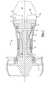
- Figure 1 is a schematic view of a turbine engine 10. Air is pulled into the turbine engine 10 by a fan 12 and flows through a low pressure compressor 14 and a high pressure compressor 16. Fuel is mixed with the oxygen and combustion occurs within the combustor 20. Exhaust from combustion flows through a high pressure turbine 22 and a low pressure turbine 24 prior to leaving the engine through the exhaust nozzle 26.
- the example engine 10 includes an afterburner, 30.
- a turbine exhaust case 28 is located in front of the exhaust nozzle 26 and behind the low pressure turbine 24 to house the afterburner 30.
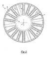
- an end view of the afterburner 30 looking forward in the engine 10 is shown.
- An afterburner trailing edge 31 is located at the aft end of the afterburner 30 and an afterburner leading edge 33 is located at the forward edge of the afterburner 30. Air flows into the afterburner 30 at the leading edge 33 and exits at the trailing edge 31.
- the afterburner 30 includes vanes 50 positioned between an outer case 35 and an inner case 37 to support the inner case 37.
- the afterburner 30 has trailing edge boxes 32 that house afterburner components.
- the trailing edge boxes 32 are positioned between the outer case 35 and an inner case 37 similarly to the vanes 50.
- the trailing edge boxes 32 are radially spaced about the inner case 35.
- the trailing edge boxes 32 are symmetrically disposed about an axis A of the engine and about the outer case 35 and interposed with the vanes 50.
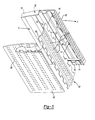
- FIG 3 shows an interior view of one trailing edge box 32.
- An afterburner spraybar (not shown) is housed within the trailing edge box 32 and provides fuel to mix with the leftover oxygen for a second combustion.
- Cooling holes 58 are located on a first wall 42 and a second wall 44 of the trailing edge box 32 to allow oxygen to enter the trailing edge box 32.
- the exhaust from the second combustion leaves the trailing edge box 32 through exhaust holes 54 on a flameholder 43 of the trailing edge box 32. Exhaust flow is depicted by arrow F.
- the second combustion provides additional thrust to the turbine engine 10.
- Exhaust from the first and second combustion exits the turbine engine 10 through the exhaust nozzle 26 (shown in Figure 1).
- the example trailing edge box 32 is formed of sheet metal.
- the sheet metal is formed to create corrugations 40 on the internal side of the first wall 42 and the second wall 44 of the trailing edge box 32.
- the first wall 42 and the second wall 44 are opposing sides of the trailing edge box 32.
- the corrugations 40 may be formed as one piece with the first wall 42 and the second wall 44 or may be separate pieces of sheet metal which are attached to the first wall 42 and the second wall 44.
- a metering plate 62 fits within slots 66 in corrugations 40 on the first wall and slots 72 formed in the corrugations 40 of the second wall 44. When assembled the metering plate 62 is generally parallel to the flameholder 43. Exhaust holes 54 in the metering plate 62 and flameholder 43 allow exhaust gases to exit the trailing edge box.
- the flameholder 43 forms a wall at the trailing edge of the trailing edge box 32. The flameholder 43 assists in combustion by controlling the rate at which air flows through the trailing edge box 32, thereby providing for the desired second combustion.
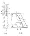
- FIG 4 is an end view of the trailing edge box 32 with the flameholder 43 removed for clarity. Fasteners 60 for the flameholder 43 are shown.
- the metering plate 62 is located at the aft end of the trailing edge box 32.
- the metering plate 62 creates a pressure drop from the front of the trailing edge box 32 through to the aft of the trailing edge box 32.
- the desired pressure drop is generated by sizing the exhaust holes 54 to control airflow F at a desired pressure. Further, the number of exhaust holes 54 is determined to provide the required airflow that provides the desired pressure drop.
- the metering plate 62 meters flow so that there is always a positive pressure across the flameholder 43 (shown in Figure 5).
- the positive pressure flowing out of a flameholder 43 is a result of the pressure drop created by the metering plate 62.
- the positive pressure on the flameholder 43 creates a cool film on a coated edge 64 of the flameholder 43.
- a portion of the metering plate 62 has been removed to show the corrugations 40 on the first wall 42 and the corrugations 40 on the second wall 44. Slots 66 and 72 are formed in the straight sides 46 of the corrugations 40 for receiving the metering plate 62.
- Figure 5 shows a cross-section through the trailing edge box 32 looking from the outer case 35 toward the inner case 37.
- the corrugations 40 reinforce the walls of the trailing edge box 32 to provide structural support to the trailing edge box 32.
- the corrugations 40 have generally straight sides 46 extending from the first side 42 and the second side 44 of the trailing edge box 32.
- the corrugations 40 on the first side 42 have the slots 66 disposed within the straight side 46 for receiving a first end 68 of the metering plate 62.
- the metering plate 62 also has a second end 70. The second end 70 of the metering plate 62 is received within the slots 72 disposed within the straight side 46 in the corrugations 40 on the second side 44 of the trailing edge box 32.
- the first end 68 and the second end 70 have hooks 74 which are received within the slots 66 and 72.
- force is applied to the metering plate 62 as a result of airflow through the engine 10, depicted by arrows F.
- the force applied by the airflow F outwardly against the first and second walls 42 and 44.
- This outward applied force causes an interference fit between the slots 66 and 72 and the first end 68 and second end 70 of the metering plate 62.
- the interference fit secures the metering plate 62 rigidly to the corrugations 40.
- the metering plate 62 is at an angle to the load L placed on the trailing edge box 32.
- the load L on the trailing edge box 32 creates pressure on the hooks 74 of the metering plate 62 to retain the metering plate 62 within the slots 66 and 72.
- the metering plate 62 also adds structural support to the trailing edge box 32 by reinforcing and connecting the first side 42 with the second side 44.
Landscapes
- Engineering & Computer Science (AREA)
- Chemical & Material Sciences (AREA)
- Combustion & Propulsion (AREA)
- Mechanical Engineering (AREA)
- General Engineering & Computer Science (AREA)
- Turbine Rotor Nozzle Sealing (AREA)
Abstract
Description
- The invention is an arrangement to support and retain a metering plate in a turbine engine. More particularly, this invention relates to retaining a metering plate within a trailing edge box without requiring additional fasteners.
- Turbine engines may have afterburners, or augmenters, located at the rear of the engine before the exhaust nozzle. Afterburners utilize unused oxygen from the turbine engine to obtain a second combustion. The second combustion provides additional thrust for the turbine engine. An afterburner has a trailing edge box to house a fuel spraybar that sprays fuel to mix with unused oxygen. A metering plate is housed in the trailing edge box to create a pressure drop from the front of the trailing edge box toward a flameholder at the rear of the trailing edge box. The pressure drop creates airflow that causes a cooling air film to develop on a coated surface of the flameholder.
- Turbine engines often must meet special requirements. One such special requirement is that all interfaces must be internal to the major components. Due to this requirement packaging for fasteners and other structural parts is difficult. As a result there is little room for fasteners at the rear of the trailing edge box for supporting the metering plate.
- Additionally, turbine engines and afterburners are subject to heavy vibrations, which may cause high wear on the engine and afterburner components.
- A lighter arrangement to retain a metering plate while providing support to a turbine engine component is needed.
- A turbine engine afterburner disclosed herein has trailing edge boxes to house the afterburner components. Each trailing edge box uses a metering plate to create a pressure drop from the front to the rear of the trailing edge box where a flameholder is located. The pressure drop creates a positive pressure flowing out of the flameholder to create a film of cooling air on the surface of the flameholder.
- Slots for receiving the metering plate are located in corrugations formed within the trailing edge box. The ends of the metering plate have hooks that correspond to the location of the slots. The hooks are placed within the slots to retain the metering plate. Once in place force is applied to the metering plate as a result of airflow through the trailing edge box.
- The metering plate is at an angle to the load placed on the trailing edge box to create pressure on the hooks and retain the metering plate within the slots. The metering plate also adds structural support to the trailing edge box by reinforcing and connecting the walls of the trailing edge box.
- Accordingly, the example trailing edge box of this invention retains a metering plate and strengthens the trailing edge box while eliminating the need for metering plate fasteners.
- These and other features of the present invention can be best understood from the following specification and drawings, the following of which is a brief description.
-
- Figure 1 is a schematic view of a turbine engine with an afterburner;
- Figure 2 is a end view of the afterburner showing trailing edge boxes according to this invention;
- Figure 3 is an interior view of a trailing edge box of the present invention;
- Figure 4 is an end view of a trailing edge box of the present invention; and
- Figure 5 is a cross-sectional view of one embodiment of the trailing edge box of the present invention.
- Figure 1 is a schematic view of a
turbine engine 10. Air is pulled into theturbine engine 10 by afan 12 and flows through alow pressure compressor 14 and ahigh pressure compressor 16. Fuel is mixed with the oxygen and combustion occurs within thecombustor 20. Exhaust from combustion flows through ahigh pressure turbine 22 and alow pressure turbine 24 prior to leaving the engine through theexhaust nozzle 26. Theexample engine 10 includes an afterburner, 30. Aturbine exhaust case 28 is located in front of theexhaust nozzle 26 and behind thelow pressure turbine 24 to house theafterburner 30. - Referring to Figure 2, an end view of the
afterburner 30 looking forward in theengine 10 is shown. An afterburnertrailing edge 31 is located at the aft end of theafterburner 30 and anafterburner leading edge 33 is located at the forward edge of theafterburner 30. Air flows into theafterburner 30 at the leadingedge 33 and exits at thetrailing edge 31. Theafterburner 30 includesvanes 50 positioned between anouter case 35 and aninner case 37 to support theinner case 37. Theafterburner 30 has trailingedge boxes 32 that house afterburner components. Thetrailing edge boxes 32 are positioned between theouter case 35 and aninner case 37 similarly to thevanes 50. Thetrailing edge boxes 32 are radially spaced about theinner case 35. Thetrailing edge boxes 32 are symmetrically disposed about an axis A of the engine and about theouter case 35 and interposed with thevanes 50. - Figure 3 shows an interior view of one
trailing edge box 32. An afterburner spraybar (not shown) is housed within thetrailing edge box 32 and provides fuel to mix with the leftover oxygen for a second combustion.Cooling holes 58 are located on afirst wall 42 and asecond wall 44 of thetrailing edge box 32 to allow oxygen to enter thetrailing edge box 32. The exhaust from the second combustion leaves thetrailing edge box 32 throughexhaust holes 54 on aflameholder 43 of thetrailing edge box 32. Exhaust flow is depicted by arrow F. The second combustion provides additional thrust to theturbine engine 10. Exhaust from the first and second combustion exits theturbine engine 10 through the exhaust nozzle 26 (shown in Figure 1). - The example trailing
edge box 32 is formed of sheet metal. The sheet metal is formed to createcorrugations 40 on the internal side of thefirst wall 42 and thesecond wall 44 of thetrailing edge box 32. Thefirst wall 42 and thesecond wall 44 are opposing sides of thetrailing edge box 32. When thetrailing edge box 32 is assembled the corrugations from each side face one another running laterally from anouter case edge 39 toward aninner case edge 41. Thecorrugations 40 may be formed as one piece with thefirst wall 42 and thesecond wall 44 or may be separate pieces of sheet metal which are attached to thefirst wall 42 and thesecond wall 44. - A
metering plate 62 fits withinslots 66 incorrugations 40 on the first wall andslots 72 formed in thecorrugations 40 of thesecond wall 44. When assembled themetering plate 62 is generally parallel to theflameholder 43.Exhaust holes 54 in themetering plate 62 andflameholder 43 allow exhaust gases to exit the trailing edge box. Theflameholder 43 forms a wall at the trailing edge of thetrailing edge box 32. Theflameholder 43 assists in combustion by controlling the rate at which air flows through thetrailing edge box 32, thereby providing for the desired second combustion. - Figure 4 is an end view of the
trailing edge box 32 with theflameholder 43 removed for clarity.Fasteners 60 for theflameholder 43 are shown. themetering plate 62 is located at the aft end of the trailingedge box 32. Themetering plate 62 creates a pressure drop from the front of the trailingedge box 32 through to the aft of the trailingedge box 32. The desired pressure drop is generated by sizing the exhaust holes 54 to control airflow F at a desired pressure. Further, the number of exhaust holes 54 is determined to provide the required airflow that provides the desired pressure drop. Themetering plate 62 meters flow so that there is always a positive pressure across the flameholder 43 (shown in Figure 5). The positive pressure flowing out of aflameholder 43 is a result of the pressure drop created by themetering plate 62. The positive pressure on theflameholder 43 creates a cool film on acoated edge 64 of theflameholder 43. - A portion of the
metering plate 62 has been removed to show thecorrugations 40 on thefirst wall 42 and thecorrugations 40 on thesecond wall 44.Slots straight sides 46 of thecorrugations 40 for receiving themetering plate 62. - Figure 5 shows a cross-section through the trailing
edge box 32 looking from theouter case 35 toward theinner case 37. Thecorrugations 40 reinforce the walls of the trailingedge box 32 to provide structural support to the trailingedge box 32. Thecorrugations 40 have generally straight sides 46 extending from thefirst side 42 and thesecond side 44 of the trailingedge box 32. Thecorrugations 40 on thefirst side 42 have theslots 66 disposed within thestraight side 46 for receiving afirst end 68 of themetering plate 62. Themetering plate 62 also has asecond end 70. Thesecond end 70 of themetering plate 62 is received within theslots 72 disposed within thestraight side 46 in thecorrugations 40 on thesecond side 44 of the trailingedge box 32. Thefirst end 68 and thesecond end 70 havehooks 74 which are received within theslots slots metering plate 62 as a result of airflow through theengine 10, depicted by arrows F. The force applied by the airflow F outwardly against the first andsecond walls slots first end 68 andsecond end 70 of themetering plate 62. The interference fit secures themetering plate 62 rigidly to thecorrugations 40. - As a result of the
angular sides 46 of thecorrugations 40, themetering plate 62 is at an angle to the load L placed on the trailingedge box 32. The load L on the trailingedge box 32 creates pressure on thehooks 74 of themetering plate 62 to retain themetering plate 62 within theslots metering plate 62 also adds structural support to the trailingedge box 32 by reinforcing and connecting thefirst side 42 with thesecond side 44. - Although a preferred embodiment of this invention has been disclosed, a worker of ordinary skill in this art would recognize that certain modifications would come within the scope of this invention. For that reason, the following claims should be studied to determine the true scope and content of this invention.
Claims (13)
- A turbine engine (10) comprising:a trailing edge box (32) including a first side (42) and a second side (44) spaced apart to define a cavity, the first side (42) including a first slot (66) and the second side (44) including a second slot (72); anda metering plate (62) extending between the first side (42) and the second side (44), said metering plate (62) disposed within the first slot (66) and the second slot (72).
- The turbine engine of claim 1, wherein said metering plate (62) provides structural support for said trailing edge box (32).
- The turbine engine of claim 1 or 2 , wherein the trailing edge box (32) has a lower pressure on a first side of the metering plate (62) and a higher pressure on a second side of the metering plate (62).
- A trailing edge box (32) comprising:a first side (42) and a second side (44) spaced apart to define a cavity, the first side (42) including a first slot (66) and the second side (44) including a second slot (72); anda metering plate (62) extending between the first side (42) and the second side (44), said metering plate (62) disposed within the first slot (66) and the second slot (72).
- The turbine engine or trailing edge box of any preceding claim, wherein the trailing edge box (32) includes a flameholder (43) disposed between the first side (42) and the second side (44) and spaced from the metering plate (62).
- The turbine engine or trailing edge box of claim 5, wherein the metering plate (62) includes a first side having a first pressure and second side having a higher pressure then the first pressure, and the flameholder (43) is spaced apart from the first side of the metering plate (62).
- The turbine engine or trailing edge box of any preceding claim, wherein said metering plate (62) is at an angle relative to a load placed on the trailing edge box (32) to retain the metering plate (62) within the first slot (66) and the second slot (72).
- The turbine engine or trailing edge box of any preceding claim, wherein the first slot (66) is defined within a corrugation (40) formed in the first side (42) and the second slot (72) is defined within a corrugation (40) formed in the second side (44).
- The turbine engine or trailing edge box of any preceding claim, wherein the metering plate (62) includes opposing ends and a hook portion (74) formed at each of the opposing ends to interfit with the first slot (66) and the second slot (72).
- The turbine engine or trailing edge box of any preceding claim, wherein the trailing edge box (32) and the metering plate (62) are formed from sheet metal.
- A method of installing a metering plate (62) in a turbine engine (10) comprising:a) providing a metering plate (62) with a first end having a first hook (74) and a second end opposing said first end having a second hook (74);b) inserting the first hook (74) within a slot (66) in a first wall (42) of a component; andc) inserting the second hook (74) within a slot (72) in a second wall (44) of the component opposing the support of the component.
- The method of claim 11, further including:d) placing a load on said metering plate (62) in a direction preventing removal of the metering plate (62).
- The method of claim 11 or 12, including the step of attaching a flameholder (43) to the first wall (42) and the second wall (44) a distance from the metering plate (62) to define an enclosed space between the metering plate (62) and the flameholder (43).
Applications Claiming Priority (1)
| Application Number | Priority Date | Filing Date | Title |
|---|---|---|---|
| US11/386,305 US20070220892A1 (en) | 2006-03-22 | 2006-03-22 | Structural metering plate |
Publications (2)
| Publication Number | Publication Date |
|---|---|
| EP1840468A2 true EP1840468A2 (en) | 2007-10-03 |
| EP1840468A3 EP1840468A3 (en) | 2010-09-08 |
Family
ID=38112233
Family Applications (1)
| Application Number | Title | Priority Date | Filing Date |
|---|---|---|---|
| EP07250242A Withdrawn EP1840468A3 (en) | 2006-03-22 | 2007-01-22 | Structural metering plate |
Country Status (3)
| Country | Link |
|---|---|
| US (1) | US20070220892A1 (en) |
| EP (1) | EP1840468A3 (en) |
| JP (1) | JP2007255881A (en) |
Cited By (1)
| Publication number | Priority date | Publication date | Assignee | Title |
|---|---|---|---|---|
| CN106678873A (en) * | 2016-11-16 | 2017-05-17 | 西北工业大学 | Integrated afterburner of supporting plate tail dual oil channels |
Families Citing this family (2)
| Publication number | Priority date | Publication date | Assignee | Title |
|---|---|---|---|---|
| CN106678876B (en) * | 2016-11-18 | 2019-03-01 | 西北工业大学 | An afterburner with airflow channel designed in the rectifier support plate |
| CN115164233B (en) * | 2022-08-18 | 2023-04-25 | 中国航空发动机研究院 | Baffle assembly and stabilizer |
Family Cites Families (11)
| Publication number | Priority date | Publication date | Assignee | Title |
|---|---|---|---|---|
| US3701255A (en) * | 1970-10-26 | 1972-10-31 | United Aircraft Corp | Shortened afterburner construction for turbine engine |
| US4040767A (en) * | 1975-06-02 | 1977-08-09 | United Technologies Corporation | Coolable nozzle guide vane |
| US4570703A (en) * | 1982-02-08 | 1986-02-18 | The United States Of America As Represented By The United States Department Of Energy | Tube support grid and spacer therefor |
| FR2646880A1 (en) * | 1989-05-11 | 1990-11-16 | Snecma | THERMAL PROTECTION SHIRT FOR POST-COMBUSTION CHANNEL OR TRANSITION OF TURBOREACTOR |
| US5385015A (en) * | 1993-07-02 | 1995-01-31 | United Technologies Corporation | Augmentor burner |
| US5396763A (en) * | 1994-04-25 | 1995-03-14 | General Electric Company | Cooled spraybar and flameholder assembly including a perforated hollow inner air baffle for impingement cooling an outer heat shield |
| US5396761A (en) * | 1994-04-25 | 1995-03-14 | General Electric Company | Gas turbine engine ignition flameholder with internal impingement cooling |
| GB9623615D0 (en) * | 1996-11-13 | 1997-07-09 | Rolls Royce Plc | Jet pipe liner |
| US5813221A (en) * | 1997-01-14 | 1998-09-29 | General Electric Company | Augmenter with integrated fueling and cooling |
| ATE233393T1 (en) * | 1997-12-08 | 2003-03-15 | Volvo Aero Corp | FLAME HOLDER FOR GAS TURBINE AFTERBURNERS |
| US7647775B2 (en) * | 2005-06-30 | 2010-01-19 | United Technologies Corporation | Augmentor spray bars |
-
2006
- 2006-03-22 US US11/386,305 patent/US20070220892A1/en not_active Abandoned
- 2006-12-12 JP JP2006333944A patent/JP2007255881A/en active Pending
-
2007
- 2007-01-22 EP EP07250242A patent/EP1840468A3/en not_active Withdrawn
Cited By (2)
| Publication number | Priority date | Publication date | Assignee | Title |
|---|---|---|---|---|
| CN106678873A (en) * | 2016-11-16 | 2017-05-17 | 西北工业大学 | Integrated afterburner of supporting plate tail dual oil channels |
| CN106678873B (en) * | 2016-11-16 | 2019-03-01 | 西北工业大学 | A dual oil circuit integrated afterburner at the tail of the support plate |
Also Published As
| Publication number | Publication date |
|---|---|
| US20070220892A1 (en) | 2007-09-27 |
| EP1840468A3 (en) | 2010-09-08 |
| JP2007255881A (en) | 2007-10-04 |
Similar Documents
| Publication | Publication Date | Title |
|---|---|---|
| US11781447B2 (en) | Low pressure ratio fan engine having a dimensional relationship between inlet and fan size | |
| EP3543512B1 (en) | Turbofan engine having a dimensional relationship between inlet and fan size | |
| JP5264184B2 (en) | Bleed structure for a bleed passage in a gas turbine engine | |
| US6988674B2 (en) | Method and apparatus for suppressing infrared signatures | |
| EP3184750B1 (en) | Impingement cooling baffle | |
| US20130323067A1 (en) | Turbine rotor cover plate lock | |
| US20160108854A1 (en) | Low pressure ratio fan engine having a dimensional relationship between inlet and fan size | |
| CN109539308B (en) | Angled combustor for gas turbine engine | |
| US11220912B2 (en) | Airfoil with y-shaped rib | |
| US6401447B1 (en) | Combustor apparatus for a gas turbine engine | |
| US20150241063A1 (en) | Combustor with grommet having projecting lip | |
| EP3034793B1 (en) | Gas turbine engine component with increased cooling capacity | |
| EP1840468A2 (en) | Structural metering plate | |
| US7179047B2 (en) | Vane apparatus for a gas turbine engine | |
| EP3323981B1 (en) | Airfoil pieces secured with endwall section | |
| US10655502B2 (en) | Stator assembly with retention clip for gas turbine engine | |
| US10502070B2 (en) | Airfoil with laterally insertable baffle | |
| US11359497B1 (en) | Vane with baffle and recessed spar | |
| EP1835230B1 (en) | Supporting structure for spray bars | |
| US10975730B2 (en) | Duct assembly for a gas turbine engine | |
| US20180135459A1 (en) | Airfoil with sealed baffle | |
| US10590952B2 (en) | Nacelle assembly |
Legal Events
| Date | Code | Title | Description |
|---|---|---|---|
| PUAI | Public reference made under article 153(3) epc to a published international application that has entered the european phase |
Free format text: ORIGINAL CODE: 0009012 |
|
| AK | Designated contracting states |
Kind code of ref document: A2 Designated state(s): AT BE BG CH CY CZ DE DK EE ES FI FR GB GR HU IE IS IT LI LT LU LV MC NL PL PT RO SE SI SK TR |
|
| AX | Request for extension of the european patent |
Extension state: AL BA HR MK YU |
|
| PUAL | Search report despatched |
Free format text: ORIGINAL CODE: 0009013 |
|
| AK | Designated contracting states |
Kind code of ref document: A3 Designated state(s): AT BE BG CH CY CZ DE DK EE ES FI FR GB GR HU IE IS IT LI LT LU LV MC NL PL PT RO SE SI SK TR |
|
| AX | Request for extension of the european patent |
Extension state: AL BA HR MK RS |
|
| AKY | No designation fees paid | ||
| REG | Reference to a national code |
Ref country code: DE Ref legal event code: R108 Effective date: 20110412 |
|
| STAA | Information on the status of an ep patent application or granted ep patent |
Free format text: STATUS: THE APPLICATION IS DEEMED TO BE WITHDRAWN |
|
| 18D | Application deemed to be withdrawn |
Effective date: 20110309 |