EP1840460A1 - Gas burner - Google Patents
Gas burner Download PDFInfo
- Publication number
- EP1840460A1 EP1840460A1 EP06251695A EP06251695A EP1840460A1 EP 1840460 A1 EP1840460 A1 EP 1840460A1 EP 06251695 A EP06251695 A EP 06251695A EP 06251695 A EP06251695 A EP 06251695A EP 1840460 A1 EP1840460 A1 EP 1840460A1
- Authority
- EP
- European Patent Office
- Prior art keywords
- gas burner
- cylindrical wall
- inner rim
- extending portion
- circumferential inner
- Prior art date
- Legal status (The legal status is an assumption and is not a legal conclusion. Google has not performed a legal analysis and makes no representation as to the accuracy of the status listed.)
- Withdrawn
Links
Images


Classifications
-
- F—MECHANICAL ENGINEERING; LIGHTING; HEATING; WEAPONS; BLASTING
- F23—COMBUSTION APPARATUS; COMBUSTION PROCESSES
- F23D—BURNERS
- F23D14/00—Burners for combustion of a gas, e.g. of a gas stored under pressure as a liquid
- F23D14/02—Premix gas burners, i.e. in which gaseous fuel is mixed with combustion air upstream of the combustion zone
-
- F—MECHANICAL ENGINEERING; LIGHTING; HEATING; WEAPONS; BLASTING
- F23—COMBUSTION APPARATUS; COMBUSTION PROCESSES
- F23D—BURNERS
- F23D14/00—Burners for combustion of a gas, e.g. of a gas stored under pressure as a liquid
- F23D14/46—Details
- F23D14/70—Baffles or like flow-disturbing devices
-
- F—MECHANICAL ENGINEERING; LIGHTING; HEATING; WEAPONS; BLASTING
- F23—COMBUSTION APPARATUS; COMBUSTION PROCESSES
- F23D—BURNERS
- F23D2203/00—Gaseous fuel burners
- F23D2203/10—Flame diffusing means
- F23D2203/101—Flame diffusing means characterised by surface shape
- F23D2203/1012—Flame diffusing means characterised by surface shape tubular
-
- F—MECHANICAL ENGINEERING; LIGHTING; HEATING; WEAPONS; BLASTING
- F23—COMBUSTION APPARATUS; COMBUSTION PROCESSES
- F23D—BURNERS
- F23D2900/00—Special features of, or arrangements for burners using fluid fuels or solid fuels suspended in a carrier gas
- F23D2900/00003—Fuel or fuel-air mixtures flow distribution devices upstream of the outlet
Definitions
- the present invention relates to a gas burner, and particularly but not exclusively to a gas burner for use in domestic heating appliances.
- the burner may be of the 'premix' type, meaning that all of the air required for complete combustion is mixed with the fuel gas prior to combustion.
- Conventional premix burners include an outer cylindrical wall defining a cavity for receiving a gas and air mixture, and the gas and air mixture passes through apertures in the outer cylindrical wall for combustion.
- An inner cylindrical wall can be located inside, and secured to, the outer cylindrical wall and a mounting member can be provided to enable the burner to be mounted in a heating appliance.
- a gas burner including:
- At least part of the circumferential inner rim may be deformable to provide the radially outwardly extending part and the at least one slot may facilitate deformation to provide the radially outwardly extending part.
- the circumferential inner rim may include a plurality of said slots extending therearound, and the slots may be equispaced around the circumferential inner rim.
- the plurality of slots may be arranged so that the circumferential inner rim is defined by a plurality of projections.
- the projections may be equispaced around the circumferential inner rim.
- Each projection may include a radially inwardly extending portion which may extend in a radially inwards direction.
- Each projection may include an axially extending portion and the axially extending portion may extend in an axial direction outwardly away from said one end of the outer substantially cylindrical wall and outwardly away from the internal cavity.
- Each projection may include a radially outwardly extending portion which may extend in a radially outwards direction.
- Each projection may have a generally C-shaped configuration and this configuration may be defined by the radially inwardly extending portion, the axially extending portion and the radially outwardly extending portion.
- Part of the axially extending portion of each of the plurality of projections may be arranged to be deformed in a radially outwards direction, possibly to thereby define the radially outwardly extending portion.
- the axially extending portions of the plurality of projections may together define the substantially circumferential inner rim of the substantially circular opening in the securing member.
- the axially extending portions may be arranged to facilitate location of the circular flange of the inner substantially cylindrical wall in the substantially circular opening.
- the gas burner may include a mounting member, possibly for mounting the gas burner in a heating appliance, and the mounting member may be secured to the burner by the securing member.
- the mounting member may include a substantially circumferential inner rim which may be located, in use, between the radially inwardly extending portion and the radially outwardly extending portion of each of the plurality of projections to thereby secure the mounting member to the gas burner.
- each of the plurality of projections may define a circumferential securing channel, and the circumferential inner rim of the mounting member may be located in the circumferential securing channel to secure the mounting member to the gas burner.
- a gas burner in accordance with any of the preceding definitions of the first aspect of the invention, the method comprising:
- Step (ii) may include bending the substantially circular flange in a radially outwards direction.
- Step (ii) may be performed by a deformation operation, such as a spinning operation.
- the method may comprise locating the substantially circumferential inner rim of the mounting member radially outwardly of the axially extending portion of each of the plurality of projections, and may thereafter comprise performing step (ii), wherein step (ii) may cause deformation of part of the axially extending portion of each of the plurality of projections to form said radially outwardly extending portion.
- each of the plurality of projections formed by step (ii) may define a circumferential securing channel, and the circumferential inner rim of the mounting member may be located in the circumferential securing channel.
- a heating appliance including a gas burner according to any of the preceding definitions of the first aspect of the invention or a gas burner manufactured in accordance with any of the preceding definitions of the second aspect of the invention.
- Fig. 1 illustrates a gas burner 10 located within a heating appliance including a combustion zone 12 and a heat exchanger 14.
- the gas burner 10 is of a known design and is described here to facilitate understanding of the present invention, described later with reference to Figs. 2 to 6.
- the gas burner 10 includes an outer cylindrical wall 16 defining an internal cavity 20 and a concentric inner cylindrical wall 18, for example in the form of a restrictor tube, located inside the internal cavity 20.
- An end cap 22 is attached to the outer cylindrical wall 16 and closes one axial end of the gas burner 10.
- a mounting member 24 is attached to the other axial end of the outer cylindrical wall 16 and extends radially outwardly therefrom.
- the gas burner 10 is attached to a housing 25 of the heating appliance via the mounting member 24.
- the outer cylindrical wall 16 is provided with a plurality of apertures in the form of flame ports 26, just a few of which are illustrated in Fig. 1.
- the flame ports 26 are about 0.8mm in diameter and their centres are about 2 to 3mm apart.
- the flame ports 26 may be arranged evenly over the whole of the outer cylindrical wall 16.
- a gas and air mixture is fed into the internal cavity 20, and this passes through the flame ports 26 in the outer cylindrical wall 16 to the outer surface 16a thereof and into the combustion zone 12, where combustion takes place.
- the heat thereby produced is utilised via the heat exchanger 14, with the flue products passing out of the unit as indicated by the arrow A.
- the inner cylindrical wall 18 is in the form of a restrictor tube, its purpose is to eliminate the interaction of sound pressure waves, created as a result of combustion, with the incoming gas and air mixture to thereby reduce the likelihood of resonance and consequent flame and flow instability.
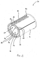
- Figs. 2, 5 and 6 illustrate a gas burner 30 according to one embodiment of the invention.
- the gas burner 30 is similar to the known gas burner 10 described above, and corresponding components are therefore designated with corresponding reference numerals.
- the gas burner 30 includes an outer cylindrical wall 16, defining an internal cavity 20 and including a plurality of flame ports 26, and a concentric inner cylindrical wall 18 open at both axial ends thereof, for example in the form of a restrictor tube.
- the gas burner 30 includes a securing member 32, the purpose of which will be described later in the specification, and this is attached to one of the axial ends 33 of the outer cylindrical wall 16, by a suitable deformation operation, such as spinning, in which the circumferential outer edge 34 of the securing member 32 is bent or folded over the circumferential edge of the of the axial end 33 of the outer cylindrical wall 16.
- the securing member 32 has a generally annular configuration and includes a circumferential inner rim 36 defining a circular opening 38.
- the circumferential inner rim 36 includes a plurality of equispaced slots 40 extending therearound and the circumferential inner rim 36 is thus defined by a plurality of equispaced projections 42.
- each projection 42 is generally L-shaped and includes a radially inwardly extending portion 44 and an axially extending portion 46 which extends in an axial direction outwardly away from the axial end 33 of the outer cylindrical wall 16 and away from the internal cavity 20.
- the inner cylindrical wall 18 includes a circular flange 48 at an axial end 50 thereof and the flange 48 is locatable inside the circumferential inner rim 36 of the securing member 32 so that it extends through the circular opening 38.
- the inner cylindrical wall 18 includes a circumferential radially outwardly projecting ridge 52 which partly defines the flange 48 and in particular limits the extent to which the inner cylindrical wall 18 can extend through the circular opening 38.
- the circular flange 48 is deformed, for example by a spinning operation, to bend it in a radially outwards direction to the position shown in Fig. 6.
- the projections 42 are also deformed, and in particular the axially extending portion 46 of each projection 42 is bent in the radially outwards direction.
- Each projection 42 is thus defined by the radially inwardly extending portion 44, part of the original axially extending portion 46 and a radially outwardly extending portion 54, and together these define a circumferentially extending securing channel 56.
- the radially extending securing channel 56 is to secure the mounting member 24 to the burner 30 without the need for welding or similar operations.
- the mounting member 24 defines a circumferential inner rim 58 which, when the burner 30 is in the part-manufactured condition, is located adjacent to, and radially outwardly of, the axially extending portions 46 of the projections 42.
- each projection 42 deforms around the circumferential inner rim 58 to define the radially outwardly extending portion 54, thereby resulting in the formation of the circumferentially extending securing channel 56 with the circumferential inner rim 58 located therein.
- a securing member 32 having a circumferential inner rim 36 including a plurality of slots 40 provides significant advantages over the prior art.
- the force required to bend the circular flange 48 of the inner cylindrical wall 18 in the radially outwards direction to secure it to the securing member 32, and to thereby secure the mounting member 24 to the burner 30, is substantially reduced when compared to a securing member without slots.
- the force required to bend the projections 42 is substantially less than the force that would be required to bend a securing member having a continuous circumferential inner rim defined, for example, by a continuous circumferential radially inwardly extending portion 44 and a continuous circumferential axially extending portion 46.
- the securing member 32 may include any suitable number of slots 40, and hence projections 42.
- the projections 42 may have a different configuration to that illustrated in the drawings.
- the slots 40, and hence projections 42, may not be equispaced.
- the securing member 32 may be secured to the outer cylindrical wall 16 by a method other than a spinning operation.
Landscapes
- Engineering & Computer Science (AREA)
- Chemical & Material Sciences (AREA)
- Combustion & Propulsion (AREA)
- Mechanical Engineering (AREA)
- General Engineering & Computer Science (AREA)
- Gas Burners (AREA)
Abstract
Description
- The present invention relates to a gas burner, and particularly but not exclusively to a gas burner for use in domestic heating appliances. The burner may be of the 'premix' type, meaning that all of the air required for complete combustion is mixed with the fuel gas prior to combustion.
- Conventional premix burners include an outer cylindrical wall defining a cavity for receiving a gas and air mixture, and the gas and air mixture passes through apertures in the outer cylindrical wall for combustion. An inner cylindrical wall can be located inside, and secured to, the outer cylindrical wall and a mounting member can be provided to enable the burner to be mounted in a heating appliance.
- It would be desirable to improve the way in which the outer and inner cylindrical walls, and the mounting member, are secured together.
- According to a first aspect of the present invention, there is provided a gas burner including:
- an outer substantially cylindrical wall defining an internal cavity for receiving a gas and air mixture and including a plurality of apertures to allow a gas and air mixture to pass from the internal cavity to an outer surface of the outer substantially cylindrical wall for combustion;
- a securing member attached to one end of the outer substantially cylindrical wall and including a circumferential inner rim defining a substantially circular opening;
- an inner substantially cylindrical wall located inside the internal cavity and defining at one end thereof a substantially circular flange, the substantially circular flange extending axially through the substantially circular opening in the securing member and in a radially outwards direction to secure the inner substantially cylindrical wall to the securing member;
- At least part of the circumferential inner rim may be deformable to provide the radially outwardly extending part and the at least one slot may facilitate deformation to provide the radially outwardly extending part.
- The circumferential inner rim may include a plurality of said slots extending therearound, and the slots may be equispaced around the circumferential inner rim.
- The plurality of slots may be arranged so that the circumferential inner rim is defined by a plurality of projections. The projections may be equispaced around the circumferential inner rim.
- Each projection may include a radially inwardly extending portion which may extend in a radially inwards direction. Each projection may include an axially extending portion and the axially extending portion may extend in an axial direction outwardly away from said one end of the outer substantially cylindrical wall and outwardly away from the internal cavity. Each projection may include a radially outwardly extending portion which may extend in a radially outwards direction.
- Each projection may have a generally C-shaped configuration and this configuration may be defined by the radially inwardly extending portion, the axially extending portion and the radially outwardly extending portion.
- Part of the axially extending portion of each of the plurality of projections may be arranged to be deformed in a radially outwards direction, possibly to thereby define the radially outwardly extending portion.
- The axially extending portions of the plurality of projections may together define the substantially circumferential inner rim of the substantially circular opening in the securing member. The axially extending portions may be arranged to facilitate location of the circular flange of the inner substantially cylindrical wall in the substantially circular opening.
- The gas burner may include a mounting member, possibly for mounting the gas burner in a heating appliance, and the mounting member may be secured to the burner by the securing member.
- The mounting member may include a substantially circumferential inner rim which may be located, in use, between the radially inwardly extending portion and the radially outwardly extending portion of each of the plurality of projections to thereby secure the mounting member to the gas burner.
- The radially inwardly extending portion, the axially extending portion and the radially outwardly extending portion of each of the plurality of projections may define a circumferential securing channel, and the circumferential inner rim of the mounting member may be located in the circumferential securing channel to secure the mounting member to the gas burner.
- According to a second aspect of the present invention, there is provided a method for manufacturing a gas burner in accordance with any of the preceding definitions of the first aspect of the invention, the method comprising:
- (i) locating the substantially circular flange in the substantially circular opening so that the substantially circular flange extends through the substantially circular opening, and
- (ii) deforming the substantially circular flange in a radially outwards direction to secure the inner substantially cylindrical wall to the securing member;
- Step (ii) may include bending the substantially circular flange in a radially outwards direction. Step (ii) may be performed by a deformation operation, such as a spinning operation.
- The method may comprise locating the substantially circumferential inner rim of the mounting member radially outwardly of the axially extending portion of each of the plurality of projections, and may thereafter comprise performing step (ii), wherein step (ii) may cause deformation of part of the axially extending portion of each of the plurality of projections to form said radially outwardly extending portion.
- The radially inwardly extending portions and the radially outwardly extending portions of each of the plurality of projections formed by step (ii) may define a circumferential securing channel, and the circumferential inner rim of the mounting member may be located in the circumferential securing channel.
- According to a third aspect of the present invention, there is provided a heating appliance including a gas burner according to any of the preceding definitions of the first aspect of the invention or a gas burner manufactured in accordance with any of the preceding definitions of the second aspect of the invention.
- An embodiment of the present invention will now be described by way of example only and with reference to the accompanying drawings, in which:-
- Fig. 1 is a diagrammatic perspective view of a conventional gas burner in place within a heating appliance;
- Fig. 2 is a diagrammatic perspective view of part of a gas burner according to one embodiment of the invention;
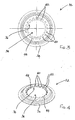
- Fig. 3 is a diagrammatic top view of a securing member of the burner of Fig. 2;
- Fig. 4 is a diagrammatic perspective view of the securing member of Fig. 3;
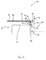
- Fig. 5 is a diagrammatic cross-sectional view of the burner of Fig. 2 in a part-manufactured condition; and
- Fig. 6 is a diagrammatic cross-sectional view of the burner of Fig. 5 in a manufactured condition.
- Fig. 1 illustrates a
gas burner 10 located within a heating appliance including acombustion zone 12 and aheat exchanger 14. Thegas burner 10 is of a known design and is described here to facilitate understanding of the present invention, described later with reference to Figs. 2 to 6. - The
gas burner 10 includes an outercylindrical wall 16 defining aninternal cavity 20 and a concentric innercylindrical wall 18, for example in the form of a restrictor tube, located inside theinternal cavity 20. Anend cap 22 is attached to the outercylindrical wall 16 and closes one axial end of thegas burner 10. Amounting member 24 is attached to the other axial end of the outercylindrical wall 16 and extends radially outwardly therefrom. Thegas burner 10 is attached to ahousing 25 of the heating appliance via themounting member 24. - The outer
cylindrical wall 16 is provided with a plurality of apertures in the form offlame ports 26, just a few of which are illustrated in Fig. 1. Theflame ports 26 are about 0.8mm in diameter and their centres are about 2 to 3mm apart. Theflame ports 26 may be arranged evenly over the whole of the outercylindrical wall 16. - In use, a gas and air mixture is fed into the
internal cavity 20, and this passes through theflame ports 26 in the outercylindrical wall 16 to theouter surface 16a thereof and into thecombustion zone 12, where combustion takes place. The heat thereby produced is utilised via theheat exchanger 14, with the flue products passing out of the unit as indicated by the arrow A. - Where the inner
cylindrical wall 18 is in the form of a restrictor tube, its purpose is to eliminate the interaction of sound pressure waves, created as a result of combustion, with the incoming gas and air mixture to thereby reduce the likelihood of resonance and consequent flame and flow instability. - Figs. 2, 5 and 6 illustrate a
gas burner 30 according to one embodiment of the invention. Thegas burner 30 is similar to the knowngas burner 10 described above, and corresponding components are therefore designated with corresponding reference numerals. - Like the
gas burner 10, thegas burner 30 includes an outercylindrical wall 16, defining aninternal cavity 20 and including a plurality offlame ports 26, and a concentric innercylindrical wall 18 open at both axial ends thereof, for example in the form of a restrictor tube. - As can be seen most clearly in Fig. 2, the
gas burner 30 includes asecuring member 32, the purpose of which will be described later in the specification, and this is attached to one of theaxial ends 33 of the outercylindrical wall 16, by a suitable deformation operation, such as spinning, in which the circumferentialouter edge 34 of thesecuring member 32 is bent or folded over the circumferential edge of the of theaxial end 33 of the outercylindrical wall 16. - The securing
member 32 has a generally annular configuration and includes a circumferentialinner rim 36 defining acircular opening 38. As best seen in Figs. 2 to 4, the circumferentialinner rim 36 includes a plurality ofequispaced slots 40 extending therearound and the circumferentialinner rim 36 is thus defined by a plurality ofequispaced projections 42. - In more detail, prior to manufacture of the
burner 30, eachprojection 42 is generally L-shaped and includes a radially inwardly extendingportion 44 and an axially extendingportion 46 which extends in an axial direction outwardly away from theaxial end 33 of the outercylindrical wall 16 and away from theinternal cavity 20. - Referring to Fig. 5, which shows the
burner 30 in an assembled and part-manufactured condition, the innercylindrical wall 18 includes acircular flange 48 at anaxial end 50 thereof and theflange 48 is locatable inside the circumferentialinner rim 36 of thesecuring member 32 so that it extends through thecircular opening 38. The innercylindrical wall 18 includes a circumferential radially outwardly projectingridge 52 which partly defines theflange 48 and in particular limits the extent to which the innercylindrical wall 18 can extend through thecircular opening 38. - In order to complete the manufacture of the
burner 30 and secure the innercylindrical wall 18 to thesecuring member 32, thecircular flange 48 is deformed, for example by a spinning operation, to bend it in a radially outwards direction to the position shown in Fig. 6. As a result, theprojections 42 are also deformed, and in particular the axially extendingportion 46 of eachprojection 42 is bent in the radially outwards direction. Eachprojection 42 is thus defined by the radially inwardly extendingportion 44, part of the original axially extendingportion 46 and a radially outwardly extendingportion 54, and together these define a circumferentially extendingsecuring channel 56. - The purpose of the radially extending securing
channel 56, once formed, is to secure themounting member 24 to theburner 30 without the need for welding or similar operations. As can be seen in Figs. 5 and 6, the mountingmember 24 defines a circumferentialinner rim 58 which, when theburner 30 is in the part-manufactured condition, is located adjacent to, and radially outwardly of, theaxially extending portions 46 of theprojections 42. As theflange 48 is subsequently deformed in the manner described above, part of theaxially extending portion 46 of eachprojection 42 deforms around the circumferentialinner rim 58 to define the radially outwardly extendingportion 54, thereby resulting in the formation of the circumferentially extending securingchannel 56 with the circumferentialinner rim 58 located therein. - The provision of a securing
member 32 having a circumferentialinner rim 36 including a plurality ofslots 40 provides significant advantages over the prior art. - In particular, due to presence of the
slots 40 and hence due to the fact that the circumferentialinner rim 36 of the securingmember 32 is discontinuous and defined by the plurality ofprojections 42, the force required to bend thecircular flange 48 of the innercylindrical wall 18 in the radially outwards direction to secure it to the securingmember 32, and to thereby secure the mountingmember 24 to theburner 30, is substantially reduced when compared to a securing member without slots. This is because the force required to bend theprojections 42 is substantially less than the force that would be required to bend a securing member having a continuous circumferential inner rim defined, for example, by a continuous circumferential radially inwardly extendingportion 44 and a continuous circumferential axially extendingportion 46. - Stresses in the
circular flange 48 and in the securingmember 32 are consequently also reduced, leading to a reduced likelihood of failure of theburner 30 when it is subjected to cyclic stresses in use as a result of rapid temperature variations. - Although embodiments of the invention have been described in the preceding paragraphs with reference to various examples, it should be appreciated that various modifications to the examples given may be made without departing from the scope of the present invention, as claimed.
- For example, the securing
member 32 may include any suitable number ofslots 40, and henceprojections 42. Theprojections 42 may have a different configuration to that illustrated in the drawings. - The
slots 40, and henceprojections 42, may not be equispaced. The securingmember 32 may be secured to the outercylindrical wall 16 by a method other than a spinning operation.
Claims (14)
- A gas burner (30) including:an outer substantially cylindrical wall (16) defining an internal cavity (20) for receiving a gas and air mixture and including a plurality of apertures (26) to allow a gas and air mixture to pass from the internal cavity (20) to an outer surface (16a) of the outer substantially cylindrical wall (16) for combustion;a securing member (32) attached to one end (33) of the outer substantially cylindrical wall (16) and including a circumferential inner rim (36) defining a substantially circular opening (38);an inner substantially cylindrical wall (18) located inside the internal cavity (20) and defining at one end (50) thereof a substantially circular flange (48), the substantially circular flange (48) extending axially through the substantially circular opening (38) in the securing member (32) and in a radially outwards direction to thereby secure the inner substantially cylindrical wall (18) to the securing member (32);characterised in that at least part of the circumferential inner rim (36) of the securing member (32) extends in a radially outwards direction and includes at least one slot (40).
- A gas burner according to claim 1, wherein the circumferential inner rim (36) includes a plurality of said slots (40) extending therearound.
- A gas burner according to claim 2, wherein the slots (40) are equispaced around the circumferential inner rim (36).
- A gas burner according to claim 2 or claim 3, wherein the plurality of slots (40) are arranged so that the circumferential inner rim (36) is defined by a plurality of projections (42).
- A gas burner according to claim 4, wherein the projections (42) are equispaced around the circumferential inner rim (36).
- A gas burner according to claim 4 or claim 5, wherein each projection (42) includes a radially inwardly extending portion (44), an axially extending portion (46) extending in an axial direction outwardly away from said one end (33) of the outer substantially cylindrical wall (16), and a radially outwardly extending portion (54).
- A gas burner according to claim 6, wherein the axially extending portions (46) of the plurality of projections (42) define the substantially circumferential inner rim (36) of the substantially circular opening (38) and are arranged to facilitate location of the circular flange (48) of the inner substantially cylindrical wall (18) in the substantially circular opening (38).
- A gas burner according to claim 6 or claim 7, wherein part of the axially extending portion (46) of each projection (42) is arranged to be bent in a radially outwards direction to define the radially outwardly extending portion (54).
- A gas burner according to any of the preceding claims, wherein the gas burner (30) includes a mounting member (24) secured thereto by the securing member (32).
- A gas burner according to claim 9 when dependent on any of claims 6 to 8, wherein the mounting member (24) includes a substantially circumferential inner rim (58) located between the radially inwardly extending portion (44) and the radially outwardly extending portion (54) of each of the plurality of projections (42) to thereby secure the mounting member (24) to the gas burner (30).
- A method for manufacturing a gas burner (30) according to any of the preceding claims, the method comprising:(i) locating the substantially circular flange (48) in the substantially circular opening (38) so that the substantially circular flange (48) extends through the substantially circular opening (38), and(ii) deforming the substantially circular flange (48) in a radially outwards direction to secure the inner substantially cylindrical wall (18) to the securing member (32);wherein step (ii) causes deformation of at least part of the circumferential inner rim (36) of the securing member (32) in a radially outwards direction.
- A method according to claim 11 when dependent on any of claims 6 to 10, wherein the method comprises locating the substantially circumferential inner rim (36) of the mounting member (24) radially outwardly of the axially extending portion (46) of each of the plurality of projections (42), and thereafter performing step (ii), wherein step (ii) causes deformation of part of the axially extending portion (46) of each of the plurality of projections (42) to form said radially outwardly extending portion (54).
- A method according to claim 12, wherein the radially inwardly extending portions (44) and the radially outwardly extending portions (54) of each of the plurality of projections (42) formed by step (ii) define a circumferential securing channel (56) in which the circumferential inner rim (58) of the mounting member (24) is located.
- A heating appliance including a gas burner (30) according to any of claims 1 to 10 or a gas burner (30) manufactured in accordance with the method of any of claims 11 to 13.
Priority Applications (1)
| Application Number | Priority Date | Filing Date | Title |
|---|---|---|---|
| EP06251695A EP1840460A1 (en) | 2006-03-29 | 2006-03-29 | Gas burner |
Applications Claiming Priority (1)
| Application Number | Priority Date | Filing Date | Title |
|---|---|---|---|
| EP06251695A EP1840460A1 (en) | 2006-03-29 | 2006-03-29 | Gas burner |
Publications (1)
| Publication Number | Publication Date |
|---|---|
| EP1840460A1 true EP1840460A1 (en) | 2007-10-03 |
Family
ID=36951400
Family Applications (1)
| Application Number | Title | Priority Date | Filing Date |
|---|---|---|---|
| EP06251695A Withdrawn EP1840460A1 (en) | 2006-03-29 | 2006-03-29 | Gas burner |
Country Status (1)
| Country | Link |
|---|---|
| EP (1) | EP1840460A1 (en) |
Cited By (8)
| Publication number | Priority date | Publication date | Assignee | Title |
|---|---|---|---|---|
| WO2009112909A3 (en) * | 2008-03-10 | 2010-06-10 | Worgas-Bruciatori - S.R.L. | Burner provided with noise reducing means |
| EP2037175A3 (en) * | 2007-09-12 | 2012-11-21 | Polidoro S.p.A. | Premixed burner |
| GB2503265A (en) * | 2012-06-21 | 2013-12-25 | Worgas Burners Ltd | Flanged gas burner assembly |
| EP2746658A1 (en) * | 2012-12-19 | 2014-06-25 | Worgas Burners Limited | Gas burner |
| EP2759768A1 (en) * | 2013-01-28 | 2014-07-30 | Worgas Burners Limited | Gas burner |
| ITMI20131481A1 (en) * | 2013-09-09 | 2015-03-10 | Worgas Bruciatori Srl | BURNER WITH PASSIVE INSULATION, IN PARTICULAR FOR AN EXTERNAL COMBUSTION ENGINE |
| WO2019011741A1 (en) * | 2017-07-13 | 2019-01-17 | Bekaert Combustion Technology B.V. | Premix gas burner |
| GB2617886A (en) * | 2022-04-21 | 2023-10-25 | Francis Kennedy John | Heating apparatus, burner device and method of construction |
Citations (5)
| Publication number | Priority date | Publication date | Assignee | Title |
|---|---|---|---|---|
| JPS57187511A (en) * | 1981-05-14 | 1982-11-18 | Akira Muramoto | Gas burner for cooking utensils |
| GB2149904A (en) * | 1983-11-17 | 1985-06-19 | Aeromatic Co Ltd | Duplex gas burner |
| EP0172945A1 (en) * | 1984-08-24 | 1986-03-05 | Furigas B.V. | Gasburner |
| US4960378A (en) * | 1987-09-26 | 1990-10-02 | Ruhrgas Aktiengesellschaft | Gas burner |
| EP1087180A1 (en) * | 1999-09-24 | 2001-03-28 | Joh. Vaillant GmbH u. Co. | Enclosed combustion system with vibration reduction device |
-
2006
- 2006-03-29 EP EP06251695A patent/EP1840460A1/en not_active Withdrawn
Patent Citations (5)
| Publication number | Priority date | Publication date | Assignee | Title |
|---|---|---|---|---|
| JPS57187511A (en) * | 1981-05-14 | 1982-11-18 | Akira Muramoto | Gas burner for cooking utensils |
| GB2149904A (en) * | 1983-11-17 | 1985-06-19 | Aeromatic Co Ltd | Duplex gas burner |
| EP0172945A1 (en) * | 1984-08-24 | 1986-03-05 | Furigas B.V. | Gasburner |
| US4960378A (en) * | 1987-09-26 | 1990-10-02 | Ruhrgas Aktiengesellschaft | Gas burner |
| EP1087180A1 (en) * | 1999-09-24 | 2001-03-28 | Joh. Vaillant GmbH u. Co. | Enclosed combustion system with vibration reduction device |
Non-Patent Citations (1)
| Title |
|---|
| PATENT ABSTRACTS OF JAPAN vol. 007, no. 037 (M - 193) 15 February 1983 (1983-02-15) * |
Cited By (12)
| Publication number | Priority date | Publication date | Assignee | Title |
|---|---|---|---|---|
| EP2037175A3 (en) * | 2007-09-12 | 2012-11-21 | Polidoro S.p.A. | Premixed burner |
| EP2037175B1 (en) | 2007-09-12 | 2016-11-23 | Polidoro S.p.A. | Premixed burner |
| WO2009112909A3 (en) * | 2008-03-10 | 2010-06-10 | Worgas-Bruciatori - S.R.L. | Burner provided with noise reducing means |
| GB2503265A (en) * | 2012-06-21 | 2013-12-25 | Worgas Burners Ltd | Flanged gas burner assembly |
| WO2013190286A1 (en) * | 2012-06-21 | 2013-12-27 | Worgas Burners Limited | Gas burner |
| EP2746658A1 (en) * | 2012-12-19 | 2014-06-25 | Worgas Burners Limited | Gas burner |
| GB2511029A (en) * | 2012-12-19 | 2014-08-27 | Worgas Burners Ltd | Gas burner |
| EP2759768A1 (en) * | 2013-01-28 | 2014-07-30 | Worgas Burners Limited | Gas burner |
| GB2510173A (en) * | 2013-01-28 | 2014-07-30 | Worgas Burners Ltd | Reduced noise burner |
| ITMI20131481A1 (en) * | 2013-09-09 | 2015-03-10 | Worgas Bruciatori Srl | BURNER WITH PASSIVE INSULATION, IN PARTICULAR FOR AN EXTERNAL COMBUSTION ENGINE |
| WO2019011741A1 (en) * | 2017-07-13 | 2019-01-17 | Bekaert Combustion Technology B.V. | Premix gas burner |
| GB2617886A (en) * | 2022-04-21 | 2023-10-25 | Francis Kennedy John | Heating apparatus, burner device and method of construction |
Similar Documents
| Publication | Publication Date | Title |
|---|---|---|
| US6939126B2 (en) | Gas burner | |
| US9772119B2 (en) | Fuel-fired heating appliance having improved burner assembly | |
| EP2227655B1 (en) | A burner, specifically a premix burner | |
| CA2449481A1 (en) | Low cost combustor burner collar | |
| EP1840460A1 (en) | Gas burner | |
| EP3006826B1 (en) | Burner | |
| CN105408602A (en) | Heat shield and method to produce same | |
| US20080210217A1 (en) | Oven or Grill Burner | |
| JP6867819B2 (en) | Gas turbine engine nozzle guide support structure | |
| EP2746658A1 (en) | Gas burner | |
| EP3529534B1 (en) | Gas burner for boiler | |
| KR101820869B1 (en) | A combustor including a fluid guide | |
| EP3018408B1 (en) | Burner | |
| EP3054222B1 (en) | A gas burner assembly | |
| CN215057659U (en) | Exhaust muffler and vehicle having the same | |
| US11808448B2 (en) | Burner assemblies for a cooktop | |
| WO2013190286A1 (en) | Gas burner | |
| EP1840461A1 (en) | End cap for a gas burner | |
| EP2513564B1 (en) | An oven comprising a burner | |
| CN217584883U (en) | Exhaust fume collecting hood assembly and fuel gas water heating device | |
| KR100513054B1 (en) | Burner made of sheet metal | |
| EP2759768A1 (en) | Gas burner | |
| CN218154450U (en) | Restrictor ring and hanging stove | |
| KR200213675Y1 (en) | Air supply pipe and exhaust pipe connet structure for a burner | |
| JP6767173B2 (en) | Burner for stove |
Legal Events
| Date | Code | Title | Description |
|---|---|---|---|
| PUAI | Public reference made under article 153(3) epc to a published international application that has entered the european phase |
Free format text: ORIGINAL CODE: 0009012 |
|
| AK | Designated contracting states |
Kind code of ref document: A1 Designated state(s): AT BE BG CH CY CZ DE DK EE ES FI FR GB GR HU IE IS IT LI LT LU LV MC NL PL PT RO SE SI SK TR |
|
| AX | Request for extension of the european patent |
Extension state: AL BA HR MK YU |
|
| 17P | Request for examination filed |
Effective date: 20071002 |
|
| AKX | Designation fees paid |
Designated state(s): AT BE BG CH CY CZ DE DK EE ES FI FR GB GR HU IE IS IT LI LT LU LV MC NL PL PT RO SE SI SK TR |
|
| RAP1 | Party data changed (applicant data changed or rights of an application transferred) |
Owner name: WORGAS BURNERS LIMITED |
|
| GRAP | Despatch of communication of intention to grant a patent |
Free format text: ORIGINAL CODE: EPIDOSNIGR1 |
|
| INTG | Intention to grant announced |
Effective date: 20140807 |
|
| RIN1 | Information on inventor provided before grant (corrected) |
Inventor name: WHITAKER, ALLAN |
|
| STAA | Information on the status of an ep patent application or granted ep patent |
Free format text: STATUS: THE APPLICATION IS DEEMED TO BE WITHDRAWN |
|
| 18D | Application deemed to be withdrawn |
Effective date: 20141218 |