EP1840343A1 - Exhaust apparatus for straddle-type vehicles and straddle-type vehicle - Google Patents
Exhaust apparatus for straddle-type vehicles and straddle-type vehicle Download PDFInfo
- Publication number
- EP1840343A1 EP1840343A1 EP07251335A EP07251335A EP1840343A1 EP 1840343 A1 EP1840343 A1 EP 1840343A1 EP 07251335 A EP07251335 A EP 07251335A EP 07251335 A EP07251335 A EP 07251335A EP 1840343 A1 EP1840343 A1 EP 1840343A1
- Authority
- EP
- European Patent Office
- Prior art keywords
- cone
- silencer
- exhaust
- punched
- muffler
- Prior art date
- Legal status (The legal status is an assumption and is not a legal conclusion. Google has not performed a legal analysis and makes no representation as to the accuracy of the status listed.)
- Granted
Links
Images


Classifications
-
- F—MECHANICAL ENGINEERING; LIGHTING; HEATING; WEAPONS; BLASTING
- F01—MACHINES OR ENGINES IN GENERAL; ENGINE PLANTS IN GENERAL; STEAM ENGINES
- F01N—GAS-FLOW SILENCERS OR EXHAUST APPARATUS FOR MACHINES OR ENGINES IN GENERAL; GAS-FLOW SILENCERS OR EXHAUST APPARATUS FOR INTERNAL COMBUSTION ENGINES
- F01N1/00—Silencing apparatus characterised by method of silencing
- F01N1/08—Silencing apparatus characterised by method of silencing by reducing exhaust energy by throttling or whirling
- F01N1/085—Silencing apparatus characterised by method of silencing by reducing exhaust energy by throttling or whirling using a central core throttling gas passage
-
- F—MECHANICAL ENGINEERING; LIGHTING; HEATING; WEAPONS; BLASTING
- F01—MACHINES OR ENGINES IN GENERAL; ENGINE PLANTS IN GENERAL; STEAM ENGINES
- F01N—GAS-FLOW SILENCERS OR EXHAUST APPARATUS FOR MACHINES OR ENGINES IN GENERAL; GAS-FLOW SILENCERS OR EXHAUST APPARATUS FOR INTERNAL COMBUSTION ENGINES
- F01N1/00—Silencing apparatus characterised by method of silencing
- F01N1/24—Silencing apparatus characterised by method of silencing by using sound-absorbing materials
-
- F—MECHANICAL ENGINEERING; LIGHTING; HEATING; WEAPONS; BLASTING
- F01—MACHINES OR ENGINES IN GENERAL; ENGINE PLANTS IN GENERAL; STEAM ENGINES
- F01N—GAS-FLOW SILENCERS OR EXHAUST APPARATUS FOR MACHINES OR ENGINES IN GENERAL; GAS-FLOW SILENCERS OR EXHAUST APPARATUS FOR INTERNAL COMBUSTION ENGINES
- F01N2310/00—Selection of sound absorbing or insulating material
- F01N2310/02—Mineral wool, e.g. glass wool, rock wool, asbestos or the like
-
- F—MECHANICAL ENGINEERING; LIGHTING; HEATING; WEAPONS; BLASTING
- F01—MACHINES OR ENGINES IN GENERAL; ENGINE PLANTS IN GENERAL; STEAM ENGINES
- F01N—GAS-FLOW SILENCERS OR EXHAUST APPARATUS FOR MACHINES OR ENGINES IN GENERAL; GAS-FLOW SILENCERS OR EXHAUST APPARATUS FOR INTERNAL COMBUSTION ENGINES
- F01N2310/00—Selection of sound absorbing or insulating material
- F01N2310/04—Metallic wool, e.g. steel wool, copper wool or the like
-
- F—MECHANICAL ENGINEERING; LIGHTING; HEATING; WEAPONS; BLASTING
- F01—MACHINES OR ENGINES IN GENERAL; ENGINE PLANTS IN GENERAL; STEAM ENGINES
- F01N—GAS-FLOW SILENCERS OR EXHAUST APPARATUS FOR MACHINES OR ENGINES IN GENERAL; GAS-FLOW SILENCERS OR EXHAUST APPARATUS FOR INTERNAL COMBUSTION ENGINES
- F01N2470/00—Structure or shape of gas passages, pipes or tubes
- F01N2470/02—Tubes being perforated
- F01N2470/04—Tubes being perforated characterised by shape, disposition or dimensions of apertures
-
- F—MECHANICAL ENGINEERING; LIGHTING; HEATING; WEAPONS; BLASTING
- F01—MACHINES OR ENGINES IN GENERAL; ENGINE PLANTS IN GENERAL; STEAM ENGINES
- F01N—GAS-FLOW SILENCERS OR EXHAUST APPARATUS FOR MACHINES OR ENGINES IN GENERAL; GAS-FLOW SILENCERS OR EXHAUST APPARATUS FOR INTERNAL COMBUSTION ENGINES
- F01N2470/00—Structure or shape of gas passages, pipes or tubes
- F01N2470/20—Dimensional characteristics of tubes, e.g. length, diameter
Landscapes
- Engineering & Computer Science (AREA)
- Chemical & Material Sciences (AREA)
- Combustion & Propulsion (AREA)
- Mechanical Engineering (AREA)
- General Engineering & Computer Science (AREA)
- Exhaust Silencers (AREA)
- Valve Device For Special Equipments (AREA)
Abstract
Description
- The present invention relates to an exhaust apparatus (or exhaust device)for a straddle-type vehicle and a straddle-type vehicle.
- A muffler (exhaust apparatus) used in a straddle-type vehicle (for example, a motorcycle) is requested to meet two demands, that is, an exhaust efficiency, at which exhaust gases discharged from an engine should be efficiently discharged, and noise reduction or noise elimination of exhaust noise, which accompanies discharge of exhaust gases of high pressure and high temperature.
- In particular, a demand for noise reduction or noise elimination is put forward in these days when regulations of noise are being made rigorous. Accordingly, it is increasingly desired that noise reduction or noise elimination be attained with an exhaust efficiency maintained. Mufflers for motorcycles are disclosed in, for example, Patent Document
JP-A-8-312324 JP-A-2003-184541 - When design of a muffler is thought only in terms of exhaust efficiency, a muffler (exhaust system) is preferably extended straight. However, such muffler is not accommodated in a vehicle body of a motorcycle. Accordingly, in order to lessen an exhaust resistance, a muffler is extended toward the rear of a vehicle body so as not to be bent suddenly as far as possible, which is actually difficult in many cases because of association with a front wheel and a bank angle. Normally, a muffler having an ideal length in terms of engine performance is in small cases accommodated intact in a configuration of a motorcycle, and as compared with design of a muffler for four-wheel passenger cars, much troubles are involved in designing a muffler, a length of which is nearly best in performance, so as to accommodate the same in a configuration of a motorcycle while maintaining a configuration as smooth as possible.
- Also, not only an exhaust efficiency but also a weight of a muffler has a great influence on controllability in motorcycles. That is, since a motorcycle is light in weight, even a weight of around 1 kg has a great influence on the motorcycle and a distant position of a center of gravity of a muffler in addition to a weight of the muffler has an adverse influence on controllability of the motorcycle.
- On the other hand, in spite of any contrivance on a construction, a muffler volume is needed to some extent in heightening a noise reducing effect. In order to conform to regulations on noise, which are increasingly made rigorous, a muffler cannot but be made large in many cases. Besides, when a metallic sheet, of which a muffler is made, is thin, it vibrates to increase noise, so that the muffler is by all means liable to be made large in weight. An increase in muffler weight will worsen controllability of a motorcycle.
- While an exhaust apparatus for a motorcycle can been designed (muffler design) under various restrictions, typically a noise reducing effect cannot be produced unless a muffler is increased in volume, whereby it is not possible to avoid a phenomenon, in which an increase in volume of a muffler brings about a decrease in controllability of a motorcycle. In a muffler in, for example, present four-stroke motocross motorcycles (in particular, sports vehicles), a silencer is typically increased in volume in order to meet noise reduction and running performance, so that the muffler is large and heavy. Current noise regulations are such that current mufflers cannot be made small and light without disregarding noise factors.
- Under such situation, the inventors of the present application have tried to realize an exhaust apparatus (muffler), which is small-sized and light while meeting a running performance (exhaust property) and a noise characteristic.
- In this manner, since a structure of a muffler for motorcycles is determined in terms of a variety of reciprocal factors, it has been extremely difficult to realize a muffler, in which miniaturization is achieved and an exhaust efficiency and a noise reducing characteristic are met.
- The invention seeks to provide a muffler for straddle-type vehicles, in which miniaturization is achieved while a demand for a noise reducing characteristic is met. SUMMARY
- Aspects of the invention are specified in the claims. The features of the claims may be combined in combinations other than those specifically set out in the claims.
- An embodiment of the invention provides an exhaust apparatus including an exhaust pipe connected to an engine and a silencer connected to the exhaust pipe, wherein the silencer is provided therein with a cone, which has a cone-shaped portion formed on a side thereof with a hole, and an inside diameter of the cone-shaped portion is increased from an upstream side to a downstream side.
- In an embodiment, the cone is a punched cone and the hole is a punched hole.
- In an embodiment, the cone is arranged on a connection of the exhaust pipe and the silencer.
- The cone can be arranged on an upstream side of the silencer.
- In an embodiment, a plurality of the cones can be provided in the silencer.
- In an embodiment, the silencer can comprise an outer cylinder and an inner cylinder accommodated in the outer cylinder, and the cone can be mounted to the inner cylinder of the silencer.
- In an embodiment, the silencer can comprise an outer cylinder and an inner cylinder accommodated in the outer cylinder, a tail pipe can be connected to the inner cylinder of the silencer and the cone can include a first cone connected to the tail pipe and a second cone connected to the inner cylinder.
- In an embodiment, at least one of the first cone and the second cone can be shaped to be opened at an upstream end thereof.
- In am embodiment, the second cone can be arranged to cover an upstream end of the first cone.
- In an embodiment, the first cone can be arranged on an upstream side of the silencer, and the second cone can be arranged on a connection of the exhaust pipe and the silencer.
- An assembly can comprise an engine and such an exhaust apparatus
- The straddle-type vehicle according to the invention comprises a straddle-type vehicle provided with and engine and the exhaust apparatus.
- In an embodiment, a downstream end of the inner cylinder of the silencer can be provided forwardly of an axle shaft of a rear wheel provided on the straddle-type vehicle.
- In an embodiment, the straddle-type vehicle engine can be a four-stroke engine.
- In an embodiment, the straddle-type vehicle can comprise an off road type motorcycle.
- In embodiment of the invention in which a cone formed on a side thereof with a hole is provided in the silencer, energy of exhaust gases, which are introduced from the exhaust pipe, can be consumed through the hole, so that it is possible to absorb exhaust noise. Besides, since an inside diameter of the cone-shaped portion of the cone is increased from an upstream side to a downstream side, it is possible to appropriately adjust a ventilation resistance in the silencer whereby it is possible to produce an exhaust noise reducing effect. Accordingly, even with a small-sized muffler, it becomes possible to produce a sufficient noise reducing effect without an increase in lengthwise dimension of the silencer.
- Embodiments of the invention are described, by way of example only, with reference to the accompanying drawings.
- Fig. 1 is a side view showing a motorcycle comprising a muffler according to an embodiment of the invention.
- Fig. 2(a) is a perspective view showing the muffler according to the embodiment of the invention, Fig. 2(b) is a view schematically showing an
engine 50, and Fig. 2(c) is a perspective view showing the muffler with achamber 21. - Figs. 3(a) to 3(c) are cross sectional views schematically showing examples of the muffler according to the embodiment of the invention.
- Fig. 4 is a perspective view showing an outward appearance so that an internal construction of a
silencer 10 is made understandable. - Figs. 5(a) and 5(b) are cross sectional views schematically a cross sectional structure of the
silencer 10 shown in Fig. 4. - Fig. 6 is a cross sectional view schematically showing an example of the muffler according to the embodiment of the invention.
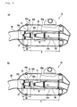
- Figs. 7(a) and 7(b) are cross sectional views schematically showing an example of the muffler according to the embodiment of the invention.
- Fig. 8 is a cross sectional views schematically showing an example of the muffler according to the embodiment of the invention.
- Figs. 9(a) and 9(b) are cross sectional views schematically showing an example of the muffler according to the embodiment of the invention.
- Figs. 10(a) and 10(b) are cross sectional views schematically showing an example of the muffler according to the embodiment of the invention.
- Figs. 11(a) and 11(b) are cross sectional views schematically showing an example of the muffler according to the embodiment of the invention.
- Fig. 12 is a cross sectional view schematically showing an outflow path of exhaust gases in a silencer according to the embodiment of the invention.
- Embodiments of the invention will be described below, by way of example, with reference to the drawings. The invention is not limited to the following embodiment.
- Fig. 1 shows a
motorcycle 1000, on which an exhaust apparatus according to an embodiment of the invention is mounted. The exhaust apparatus according to the embodiment includes anengine 50 and anexhaust apparatus 100 connected to theengine 50. Theexhaust apparatus 100 includes anexhaust pipe 20 and asilencer 10. In addition, theexhaust apparatus 100 including thesilencer 10 is in some cases referred to as "muffler" in the specification of the present application for the sake of convenience. - The
muffler 100 according to the embodiment includes theexhaust pipe 20 connected to theengine 50 of themotorcycle 1000, and thesilencer 10 connected to theexhaust pipe 20. With a construction shown in Fig. 1, atail pipe 30 is connected to thesilencer 10. - A state, in which the
muffler 100 according to the embodiment is removed from themotorcycle 1000, is shown in Fig. 2(a). Theexhaust pipe 20 and thesilencer 10 of themuffler 100 shown in Fig. 2(a) are formed with members for mounting to a vehicle body. Themuffler 100 according to the embodiment is one for four-stroke engines and themotorcycle 1000 shown in Fig. 1 is an off road vehicle. In addition, a cylinder headexhaust port portion 22 is mounted to that end of theexhaust pipe 20 shown in Fig. 2(a), which is connected to theengine 50. - The
exhaust pipe 20 connects to an exhaust hole of theengine 50 as shown in Fig. 2 (b) to lead exhaust gases from theengine 50 to thesilencer 10. In an example as shown, the cylinder headexhaust port portion 22 of theexhaust pipe 20 is connected to theengine 50. Thesilencer 10 has a noise reducing function to discharge exhaust gases led from theexhaust pipe 20 outside. In the case where thetail pipe 30 is connected to thesilencer 10, exhaust gases are discharged outside from thetail pipe 30. In addition, as shown in Fig. 2 (c), achamber 21 can be further provided in theexhaust pipe 20. In this case, exhaust gases from theengine 50 pass in thechamber 21 and is then led to thesilencer 10 to be discharged outside. - Figs. 3(a) to 3(c) are cross sectional views showing a cross sectional structure of the
silencer 10, into which exhaust gases are introduced. Thesilencer 10 according to the embodiment comprises anouter cylinder 10a and aninner cylinder 10b accommodated in theouter cylinder 10a. Also, thetail pipe 30 is connected to thesilencer 10 to lead exhaust gases outside. Punchedholes 13 are formed in at least a part (here, a region P) of theinner cylinder 10b of thesilencer 10. The punched holes 13 are small holes formed in the silencer 10 (here, theinner cylinder 10b) and serve to enable energy of exhaust gases, which are introduced from theexhaust pipe 20, to be led to theouter cylinder 10a through the small holes. - In an example shown in Fig. 3, a
sound absorbing material 15 is filled between an inner wall of theouter cylinder 10a and an outer wall of theinner cylinder 10b in a manner to come into close contact therewith. Thesound absorbing material 15 is a material capable of absorbing sound waves and can use, for example, glass wool, stainless steel wool (SUS wool), aluminum wool, ferrite, asbestos, etc. In this example, glass wool is used as thesound absorbing material 15. Thesound absorbing material 15 fairly absorbs a high frequency sound (exhaust noise in a high frequency range). - Further, the
silencer 10 according to the embodiment adopts a structure, in which a punchedcone 32 is arranged therein. The punchedcone 32 has a truncated cone shape. The punchedcone 32 comprises a member having a cone-shaped portion 31 (pyramidal-shaped portion) made of, for example, stainless steel. The cone-shapedportion 31 may be selectively formed on a part of the punchedcone 32, or the whole punched cone may comprise a cone-shaped portion. In this embodiment, the whole punchedcone 32 comprises the cone-shapedportion 31. Also, in an example as shown, the punchedcones 32 are provided in two locations (32a, 32b) in thesilencer 10. Punchedholes 14 are formed on a side of the cone-shaped portion 31 (here, the whole punched cone 32). - The punched holes 14 are a plurality of small holes (through-holes) formed on the side of the cone-shaped
portions 31 of the punchedcones 32. The punched holes 14 serve to enable energy of exhaust gases, which are introduced from theexhaust pipe 20, to be consumed through the through-holes. That is, energy of sound is consumed by viscous damping (that is, viscous damping caused by movements of an air on inner walls of the holes 14) and pressure loss damping (that is, pressure loss damping caused by the ventilation resistance in theholes 14 portions) when exhaust noise is transmitted in the punched holes 14). Thereby, it is possible to decrease the exhaust noise (noise reducing effect). In addition, while energy consumption due to pressure loss damping enables reducing the exhaust noise in the whole frequency range (that is, the whole frequency range from a low frequency range to a high frequency range), energy consumption due to viscous damping can produce a noise reducing effect especially in a high frequency range. - In addition, the punched
holes 14 can be appropriately regulated in hole diameter and pitch between respective holes so as to favorably achieve the noise reducing effect described above. That is, while pressure loss, which possibly influences the muffler performance (typically, the exhaust performance) is suppressed as far as possible, hole diameter and pitch between respective holes can be selected so as to efficiently produce the noise reducing effect. For example, with the same numerical aperture (a ratio of an area occupied by the punched holes to a total area of sides of the punched cones), as the hole diameter and the pitch decrease (that is, a state, in which thesmall holes 14 gather), a large ventilation resistance worsens the exhaust performance but a great noise reducing effect is produced. - The cone-shaped
portions 31 of the punchedcones 32 according to the embodiment are in the form of a cone with a tip end (upstream end) opened, and opening holes of the cone-shapedportions 31 of the punched cones have an opening diameter at an upstream end thereof, which is smaller than an opening diameter at a downstream end thereof. That is, the cone-shapedportions 31 of the punchedcones 32 are formed to have an inside diameter R (R1 and R2) increasing from an upstream side to a downstream side. In this manner, by forming the cone-shapedportions 31 of the punchedcones 32 so that an inside diameter R thereof increases from an upstream side to a downstream side, the cone-shapedportions 31 of the punchedcones 32 are gradually enlarged in cross sectional area in a direction, in which exhaust gases flow out. Thereby, it is possible to suitably regulate that degree (ventilation resistance), in which exhaust gases are hard to flow in thesilencer 10, thus enabling producing a noise reducing effect of themuffler 100 due to pressure loss (that is, energy consumption of exhaust gases caused by the ventilation resistance). - In this manner, the
exhaust apparatus 100 according to the embodiment can consume energy of exhaust noise through the punchedholes 14 of the cone-shapedportions 31 of the punchedcones 32 formed in thesilencer 10. Thereby, it is possible to reduce the exhaust noise (noise reducing effect). This noise reducing effect is especially effective for exhaust noise in a high frequency range. - Besides, since the cone-shaped
portions 31 of the punchedcones 32 are formed to have an inside diameter R increasing from an upstream side to a downstream side, it is possible to suitably regulate the ventilation resistance in thesilencer 10, thereby enabling producing a noise reducing effect on exhaust noise. This noise reducing effect is effective for exhaust noise in a whole frequency range. - In addition, the punched
cones 32 according to the embodiment can be preferably used for a typical, small-sized muffler, which achieves miniaturization and lightening. "Small-sized muffler" referred to herein is themuffler 100 arranged forwardly of anaxle shaft 72 of arear wheel 70 like themotorcycle 1000 shown in Fig. 1. In this example, adownstream end 10d of thesilencer 10 is positioned forwardly of a perpendicular A extended from theaxle shaft 72 of therear wheel 70 in a vertical direction. In this manner, a muffler, in which a downstream end of a silencer is positioned forwardly of an axle shaft of a rear wheel, involves a problem that a space, in which a sound absorbing material is filled, cannot be ensured adequately and so a noise reducing effect by the sound absorbing material cannot be produced adequately. - In contrast, when the punched
cones 32 according to the embodiment are adopted, even the small-sized muffler as shown in Fig. 1 can absorb exhaust noise effectively and a so-called directly transmitting sound can be suppressed. That is, a sufficient noise reducing effect can be produced without an increase in lengthwise dimension of the silencer. - In addition, the
downstream end 10d of thesilencer 10 more specifically means a downstream end of theinner cylinder 10b provided in the silencer. Accordingly, for example, even when a part of thetail pipe 30 connected to thesilencer 10 is positioned rearwardly of theaxle shaft 72 of therear wheel 70, the structure corresponds to "small-sized muffler" referred herein to. Also, the punchedcones 32 according to the embodiment are not limited to the muffler of the type shown in Fig. 1 but can be preferably used in a muffler of a so-called "cruiser". - In addition, while the cone-shaped
portions 31 of the punchedcones 32 according to the embodiment are in the form of a cone, a cross sectional shape thereof is not limited thereto but may be shaped otherwise (for example, flat oval, elliptical, polygonal, etc.). With the form of a cone, an inside diameter is increased from an upstream side to a downstream side, but a cross sectional area is increased from an upstream side to a downstream side in the case where the cross section is shaped except circular-shaped. - Further, while the punched
holes 14 in the embodiment are circular in shape, they are not limited thereto but can be shaped otherwise (for example, flat oval, elliptical, polygonal, etc.). Further, the punchedholes 14 may be varied in diameter with locations of formation, or all the plurality of punchedholes 14 as formed may be the same in diameter. - In addition, "upstream" side and "downstream" side referred to in the specification of the present application mean an upstream side and a downstream side, respectively, in a direction, in which exhaust gases in the muffler flow. In other words, "upstream" side is that side, on which an engine is arranged, and "downstream" side is that side, on which exhaust gases are discharged outside.
- A construction of an exhaust apparatus according to a further embodiment will be described below with reference to Figs. 4 and 5. Fig. 4 is a perspective view showing an outward appearance with a part of a constituent member being cut out so that an internal construction of a
silencer 10, into which exhaust gases are introduced, is made understandable. - With the
silencer 10 shown in Fig. 4, punchedcones 32 are provided in two locations (32a, 32b) on aninner cylinder 10b and an upstream end of atail pipe 30. Here, afirst cone 32a connected to thetail pipe 30 and asecond cone 32b connected to theinner cylinder 10b are included. Specifically, thefirst cone 32a is welded at the upstream end of thetail pipe 30 and thesecond cone 32b is welded to an inner wall of theinner cylinder 10b through astay portion 33. Thestay portion 33 serves to hold thesecond cone 32b in theinner cylinder 10b. - Fig. 5 schematically shows a cross sectional structure of the
silencer 10 shown in Fig. 4. As shown in Fig. 5, circular-shaped, punchedholes 14 are formed on sides (a region Q1, a region Q2) of the respective cones (32a, 32b). Also, the respective cones (32a, 32b) are formed to have an inside diameter R (R1 and R2) increasing from an upstream side to a downstream side. Further, thesecond cone 32b is provided in a manner to cover an upstream end of thefirst cone 32a. That is, thefirst cone 32a and thesecond cone 32b are arranged so as to overlap each other. - In this manner, a plurality (32a, 32b) of the punched
cones 32 are provided in the silencer whereby it is possible to effectively regulate that degree (ventilation resistance), in which exhaust gases are hard to flow, therefore enabling further heightening a noise reducing effect due to pressure loss. - Figs. 4 and 5 show a modification of the example shown in Fig. 3, in which the punched
cones 32 shaped with an upstream end closed are included. That is, while thefirst cone 32a has a shape (opened shape) with anupstream end 34a opened, thesecond cone 32b has a shape with anupstream end 34b closed. The upstream ends of the respective cones (32a, 32b) are not especially limitative in shape but may be opened in shape, or closed in shape, and a directly transmitting sound can be suppressed irrespective of the shape. However, it is preferred that one of the upstream ends of the respective cones (32a, 32b) be opened in shape and the other be closed in shape. Thereby, that degree (ventilation resistance), in which exhaust gases are hard to flow, can be made further preferable, so that it is possible to produce a noise reducing_effect. - For example, when all the upstream ends of the respective cones (32a, 32b) are closed in shape, there is possibly caused a fear that the ventilation resistance becomes too large and a decrease in exhaust efficiency is brought about, but when two cones having an opened shape and a closed shape are combined together as shown in this example, the ventilation resistance is appropriately regulated to enable preventing a directly transmitting sound, thus enabling realizing a muffler, which meets both the exhaust efficiency and the damping characteristic. In addition, the upstream ends of the punched
cones 32 can be appropriately changed in shape according to that performance (for example, exhaust performance, damping characteristic, etc.), which is demanded of a muffler. For example, as shown in Fig. 6, thefirst cone 32a may be closed in shape and thesecond cone 32b may be opened in shape. - Also, in an example shown in Fig. 5, the
second cone 32b is provided in a manner to cover thefirst cone 32a (that is, thefirst cone 32a and thesecond cone 32b overlap each other), but this arrangement is not limitative and thefirst cone 32a and thesecond cone 32b may be arranged not to overlap each other as shown in Fig. 7. In addition, Fig. 7(a) shows an example, in which thefirst cone 32a is closed in shape and thesecond cone 32a is opened in shape and Fig. 7(b) shows an example, in which thefirst cone 32a is opened in shape and thesecond cone 32a is closed in shape. - In addition, it is also possible to provide only one punched
cone 32 instead of two in number and to provide three or more punched cones. For example, Fig. 8 shows an example, in which one punchedcone 32 is arranged in asilencer 10. The punchedcone 32 is arranged on an upstream side of thesilencer 10 to be welded to an inner wall of aninner cylinder 10b through astay portion 33. Also, the punchedcone 32 is structured to have an inside diameter R increasing from an upstream side to a downstream side. In this manner, even when the number of punched cones in a silencer is one, it is fairly possible to obtain an advantage of prevention of a directly transmitting sound provided that the inside diameter R of the punchedcone 32 is enlarged in a direction, in which exhaust gases flow out. In addition, while the upstream end of the punchedcone 32 in the example as shown is closed in shape, it is not limited thereto but it is possible to select a preferable shape according to the performance (for example, exhaust performance, damping characteristic, etc. which are demanded) of a muffler. - In addition, while the punched
cone 32 shown in Fig. 8 is arranged on an upstream side of thesilencer 10, a noise reducing effect can be produced irrespective of a position, in which the punchedcone 32 is mounted, provided that the inside diameter R of a cone-shapedportion 31 of the punchedcone 32 increases from an upstream side to a downstream side. - For example, as shown in Figs. 9(a) and 9(b), it is possible to arrange a punched
cone 32 in the vicinity of an upstream end (that is, a connection of anexhaust pipe 20 and a silencer 10) of thesilencer 10. Here, the punchedcone 32 is welded to an upstream side (specifically, a diffuser) of aninner cylinder 10b through astay portion 33. In this example, anupstream end 34 of the punchedcone 32 projects further toward a upstream side from the upstream end of the silencer but a noise reducing effect in a high frequency range can be produced even in such structure by making exhaust gases somewhat hard to flow. In addition, Fig. 9 (a) shows an example, in which the upstream end of the punchedcone 32 is opened in shape and Fig. 9(b) shows an example, in which the upstream end of the punchedcone 32 is closed in shape. - Figs. 10 (a) and 10 (b) show an example, in which a punched
cone 32 is welded not to an inner wall of aninner cylinder 10b but to an upstream end of atail pipe 30. In this manner, the punchedcone 32 according to the embodiment can be mounted also to thetail pipe 30 instead of theinner cylinder 10b. - While the examples shown in Figs. 8 to 10 have been described with respect to a location of arrangement and a mount position in the case where the number of punched cones is one, the same is with the case where a plurality of punched
cones 32 are provided. That is, even in case of a plurality of punchedcones 32, a noise reducing effect in a high frequency range can be produced by making exhaust gases hard to flow provided that the inside diameter R of a cone-shapedportion 31 of the punchedcone 32 increases from an upstream side to a downstream side. Accordingly, positions, in which the punchedcones 32 are mounted, are not especially limitative. - For example, as shown in Figs. 11(a) and 11(b), a construction is possible, in which a
first cone 32a is mounted to atail pipe 30 and asecond cone 32b is mounted to an upstream side (a diffuser) of an inner cylinder. In addition, Fig. 11 (a) shows an example, in which thefirst cone 32a is closed in shape and thesecond cone 32a is opened in shape and Fig. 11(b) shows an example, in which thefirst cone 32a is opened in shape and thesecond cone 32a is closed in shape. - Also, while Figs. 3 to 11 illustrate various examples of a muffler according to the embodiments of the invention, the mufflers according to all the embodiments are the same in that the inside diameter R of the cone-shaped
portion 31 of the punchedcone 32 is enlarged in a direction, in which exhaust gases flow out, whereby the ventilation resistance in thesilencer 10 can be appropriately regulated to thereby produce a noise reducing effect on exhaust noise due to pressure loss. It is possible to appropriately select positions, in which the punchedcones 32 are formed, and the number of the punched cones according to the performance of a muffler. That is, a noise reducing effect of themuffler 100 can be appropriately regulated according to positions, in which the punchedcones 32 are formed, and the number of the punched cones. - Succeedingly, an outflow path of exhaust gases in a
silencer 10 will be described with reference to Fig. 12. Fig. 12 shows, as an example, an outflow path of exhaust gases in thesilencer 10 shown in Figs. 4 and 5. - Exhaust gases (arrow 90) led into the
silencer 10 from anexhaust pipe 20 go round (arrow 91) a side of asecond cone 32b. At this time, since an inside diameter of thesecond cone 32b is enlarged in a direction, in which exhaust gases flow out, exhaust gases meet with a resistance to be damped in energy. As a result, it is possible to absorb an exhaust noise (in particular, a high frequency sound). - A part of exhaust gases going round the side of the
second cone 32b passes through an inner wall of aninner cylinder 10b, in which exhaust noise is absorbed by a sound absorbing material 15 (arrow 92). Also, a part of exhaust gases flows into thesecond cone 32b through punchedholes 14, in which exhaust noise is also absorbed (arrow 93). - Thereafter, exhaust gases flow into a
first cone 32a from an opened, upstream end thereof (arrow 94), go round a side of thefirst cone 32a (arrow 95), pass through the inner wall of theinner cylinder 10b (arrow 96), or flow into thefirst cone 32a through the punched holes 14 (arrow 97), while exhaust noise is absorbed in respective locations, and finally pass through a tail pipe 30 (arrow 98) to be then discharged outside the silencer (arrow 99). - In an embodiment of the invention, since the punched
cone 32 formed on a side thereof with the punchedholes 14 is provided in thesilencer 10, energy of exhaust gases introduced from theexhaust pipe 20 can be consumed through the through-holes 14, and therefore, it is possible to absorb exhaust noise. Besides, since an inside diameter of the cone-shapedportion 31 of the punchedcone 32 increases from an upstream side to a downstream side, the ventilation resistance in thesilencer 10 can be appropriately regulated whereby it is possible to produce a noise reducing effect on exhaust noise. - Further, a plurality (for example, two (the
first cone 32a and thesecond cone 32b) of punchedcones 32 are provided in the silencer whereby it is possible to further effectively regulate that degree (ventilation resistance), in which exhaust gases are hard to flow, therefore enabling further heightening a damping effect due to pressure loss. At this time, a preferred muffler can be realized according to a requested performance (for example, exhaust performance, damping characteristic, etc.) by appropriately combining two cones, upstream ends of which are closed and opened in shape (for example, appropriately combining two cones, at least one of which is opened in shape). - In addition, by appropriately changing a position, in which the punched
cone 32 is mounted (for example, arranging the punchedcone 32 on a connection of theexhaust pipe 20 and thesilencer 10 as shown in Fig. 9, or arranging the punchedcone 32 on an upstream side of thesilencer 10 as shown in Fig. 10), the ventilation resistance in thesilencer 10 can be appropriately regulated whereby it is possible to produce a noise reducing effect on exhaust noise. - In addition, the punched
cone 32 can be preferably used in a small-sized muffler, in which typical miniaturization and lightening are achieved, (for example, a muffler arranged forwardly of theaxle shaft 72 of the rear wheel 70). Even such small-sized muffler can absorb an exhaust noise effectively and can suppress a so-called a directly transmitting sound. That is, it is possible to produce a sufficient noise reducing effect without an increase in lengthwise dimension of the silencer. - In addition, while Fig. 1 shows an off road type motorcycle as an example of the
motorcycle 1000, themotorcycle 1000 may be an on road type one. Also, "motorcycle" in the specification of the present application means a motorcycle and means a vehicle, which includes a bicycle with a motor (motorbike) and a scooter and can specifically turn with a vehicle body inclined. Accordingly, a three-wheeler · four-wheeler, at least one of a front wheel and a rear wheel of which has two or more wheels and which is three, four (or more) in the number of tires, can be included in "motorcycle". In addition, applicability is not limited to a motorcycle but to other vehicles capable of making use of the effect of the invention, for example, a so-called straddle-type vehicle, which includes a four-wheeled buggy, ATV (All Terrain Vehicle), and a snowmobile, except a motorcycle. - There has been described an exhaust apparatus comprising an engine, the exhaust apparatus including an exhaust pipe connected to the engine and a silencer connected to the exhaust pipe, and wherein the silencer is provided therein with a punched cone, which has a cone-shaped portion formed on a side thereof with a punched hole, and an inside diameter of the cone-shaped portion is increased from an upstream side to a downstream side.
- While the invention has been described with respect to preferred embodiments, such descriptions are not limitative but various modifications are of course possible.
- According to embodiments of the invention, it is possible to provide a muffler for a straddle-type vehicle, which achieves miniaturization while meeting a demand for a noise reducing characteristic.
-
- 10:
- silencer
- 10a:
- outer cylinder
- 10b:
- inner cylinder
- 13:
- punched hole (inner cylinder)
- 14:
- punched hole (punched cone)
- 15:
- sound absorbing material
- 20:
- exhaust pipe
- 30:
- tail pipe
- 31:
- cone-shaped portion
- 32:
- punched cone
- 32a:
- first cone
- 32b:
- second cone
- 50:
- engine
- 70:
- rear wheel
- 72:
- axle shaft of rear wheel
- 100:
- muffler (exhaust apparatus)
- 1000:
- motorcycle
- R1:
- inside diameter of cone-shaped portion (first cone)
- R2:
- inside diameter of cone-shaped portion (second cone)
Claims (15)
- An exhaust apparatus comprising an exhaust pipe for connection to an engine and a silencer connected to the exhaust pipe, the silencer being provided with a cone having a cone-shaped portion formed on a side thereof and a hole, an inside diameter of the cone-shaped portion increasing from an upstream side to a downstream side.
- The exhaust apparatus according to claim 1, wherein the cone is a punched cone and the hole is a punched hole.
- The exhaust apparatus according to claim 1 or claim 2, wherein the cone is arranged on a connection of the exhaust pipe and the silencer.
- The exhaust apparatus according to any preceding claim, wherein the cone is arranged on an upstream side of the silencer.
- The exhaust apparatus according to any preceding claim, wherein a plurality of the cones are provided in the silencer.
- The exhaust apparatus according to any preceding claim, wherein the silencer comprises an outer cylinder and an inner cylinder accommodated in the outer cylinder, and
the cone is mounted to the inner cylinder of the silencer. - The exhaust apparatus according to any preceding claim, wherein the silencer comprises an outer cylinder and an inner cylinder accommodated in the outer cylinder, and
wherein a tail pipe is connected to the silencer, and
the cone includes a first cone connected to the tail pipe, and
a second cone connected to the inner cylinder. - The exhaust apparatus according to claim 7, wherein at least one of the first cone and the second cone is shaped to be opened at an upstream end thereof.
- The exhaust apparatus according to claim 7 or claim 8, wherein the second cone is arranged to cover an upstream end of the first cone.
- The exhaust apparatus according to any of claims 7 to 9, wherein the first cone is arranged on an upstream side of the silencer, and
the second cone is arranged on a connection of the exhaust pipe and the silencer. - An assembly comprising an engine and an exhaust apparatus according to any preceding claim.
- A straddle-type vehicle comprising an engine and the exhaust apparatus according to any of claims 1 to 10.
- The straddle-type vehicle according to claim 12, wherein a downstream end of the silencer is provided forwardly of an axle shaft of a rear wheel provided on the straddle-type vehicle.
- The straddle-type vehicle according to claim 12 or claim 13, wherein the engine is a four-stroke engine.
- The straddle-type vehicle according to any of claim 12 to 14, comprising an off road type motorcycle.
Applications Claiming Priority (2)
| Application Number | Priority Date | Filing Date | Title |
|---|---|---|---|
| JP2006092334 | 2006-03-29 | ||
| JP2007031099A JP2007292048A (en) | 2006-03-29 | 2007-02-09 | Exhaust apparatus for straddle-type vehicle and straddle-type vehicle |
Publications (2)
| Publication Number | Publication Date |
|---|---|
| EP1840343A1 true EP1840343A1 (en) | 2007-10-03 |
| EP1840343B1 EP1840343B1 (en) | 2011-04-06 |
Family
ID=38158065
Family Applications (1)
| Application Number | Title | Priority Date | Filing Date |
|---|---|---|---|
| EP07251335A Not-in-force EP1840343B1 (en) | 2006-03-29 | 2007-03-28 | Exhaust apparatus for straddle-type vehicles and straddle-type vehicle |
Country Status (5)
| Country | Link |
|---|---|
| US (1) | US7766123B2 (en) |
| EP (1) | EP1840343B1 (en) |
| JP (1) | JP2007292048A (en) |
| AT (1) | ATE504726T1 (en) |
| DE (1) | DE602007013640D1 (en) |
Families Citing this family (88)
| Publication number | Priority date | Publication date | Assignee | Title |
|---|---|---|---|---|
| US7445083B2 (en) * | 2007-04-09 | 2008-11-04 | Ching-Lin Wu | Automotive muffler |
| US8596398B2 (en) | 2007-05-16 | 2013-12-03 | Polaris Industries Inc. | All terrain vehicle |
| JP2009133288A (en) * | 2007-11-30 | 2009-06-18 | Yamaha Motor Co Ltd | Exhaust device for straddle-type vehicle and straddle-type vehicle |
| JP2009287548A (en) * | 2008-04-30 | 2009-12-10 | Yamaha Motor Co Ltd | Exhaust device for straddle-type vehicle and straddle-type vehicle |
| US8994494B2 (en) | 2008-10-10 | 2015-03-31 | Polaris Industries Inc. | Vehicle security system |
| JP5853356B2 (en) * | 2009-11-17 | 2016-02-09 | スズキ株式会社 | Engine exhaust system |
| JP5598058B2 (en) * | 2010-03-31 | 2014-10-01 | スズキ株式会社 | Engine exhaust system |
| US9506407B2 (en) | 2014-01-10 | 2016-11-29 | Polaris Industries Inc. | Engine having active exhaust valve position control system and method |
| US9096289B2 (en) | 2012-02-09 | 2015-08-04 | Polaris Industries Inc. | Snowmobile |
| US10358187B2 (en) | 2014-01-10 | 2019-07-23 | Polaris Industries Inc. | Snowmobile |
| JP5906663B2 (en) * | 2011-10-27 | 2016-04-20 | スズキ株式会社 | Engine exhaust system |
| JP2014177222A (en) * | 2013-03-15 | 2014-09-25 | Yamaha Motor Co Ltd | Saddle-riding type vehicle |
| DE102013224562A1 (en) * | 2013-11-29 | 2015-06-03 | Bayerische Motoren Werke Aktiengesellschaft | Device for receiving a rear silencer of a bicycle |
| US9845004B2 (en) * | 2014-01-10 | 2017-12-19 | Polaris Industries Inc. | Snowmobile |
| CN109080735B (en) | 2014-05-16 | 2022-05-03 | 迪根特技术公司 | Modular forming node for vehicle chassis and using method thereof |
| AU2015284265A1 (en) | 2014-07-02 | 2017-02-16 | Divergent Technologies, Inc. | Systems and methods for fabricating joint members |
| US10173255B2 (en) | 2016-06-09 | 2019-01-08 | Divergent Technologies, Inc. | Systems and methods for arc and node design and manufacture |
| US11155005B2 (en) | 2017-02-10 | 2021-10-26 | Divergent Technologies, Inc. | 3D-printed tooling and methods for producing same |
| US10759090B2 (en) | 2017-02-10 | 2020-09-01 | Divergent Technologies, Inc. | Methods for producing panels using 3D-printed tooling shells |
| US10898968B2 (en) | 2017-04-28 | 2021-01-26 | Divergent Technologies, Inc. | Scatter reduction in additive manufacturing |
| US10703419B2 (en) | 2017-05-19 | 2020-07-07 | Divergent Technologies, Inc. | Apparatus and methods for joining panels |
| US11358337B2 (en) | 2017-05-24 | 2022-06-14 | Divergent Technologies, Inc. | Robotic assembly of transport structures using on-site additive manufacturing |
| US11123973B2 (en) | 2017-06-07 | 2021-09-21 | Divergent Technologies, Inc. | Interconnected deflectable panel and node |
| US10919230B2 (en) | 2017-06-09 | 2021-02-16 | Divergent Technologies, Inc. | Node with co-printed interconnect and methods for producing same |
| US10781846B2 (en) | 2017-06-19 | 2020-09-22 | Divergent Technologies, Inc. | 3-D-printed components including fasteners and methods for producing same |
| US10994876B2 (en) | 2017-06-30 | 2021-05-04 | Divergent Technologies, Inc. | Automated wrapping of components in transport structures |
| US11022375B2 (en) | 2017-07-06 | 2021-06-01 | Divergent Technologies, Inc. | Apparatus and methods for additively manufacturing microtube heat exchangers |
| US10895315B2 (en) | 2017-07-07 | 2021-01-19 | Divergent Technologies, Inc. | Systems and methods for implementing node to node connections in mechanized assemblies |
| US10751800B2 (en) | 2017-07-25 | 2020-08-25 | Divergent Technologies, Inc. | Methods and apparatus for additively manufactured exoskeleton-based transport structures |
| US10940609B2 (en) | 2017-07-25 | 2021-03-09 | Divergent Technologies, Inc. | Methods and apparatus for additively manufactured endoskeleton-based transport structures |
| US10605285B2 (en) | 2017-08-08 | 2020-03-31 | Divergent Technologies, Inc. | Systems and methods for joining node and tube structures |
| US10357959B2 (en) | 2017-08-15 | 2019-07-23 | Divergent Technologies, Inc. | Methods and apparatus for additively manufactured identification features |
| US11306751B2 (en) | 2017-08-31 | 2022-04-19 | Divergent Technologies, Inc. | Apparatus and methods for connecting tubes in transport structures |
| US10960611B2 (en) | 2017-09-06 | 2021-03-30 | Divergent Technologies, Inc. | Methods and apparatuses for universal interface between parts in transport structures |
| US11292058B2 (en) | 2017-09-12 | 2022-04-05 | Divergent Technologies, Inc. | Apparatus and methods for optimization of powder removal features in additively manufactured components |
| US10814564B2 (en) | 2017-10-11 | 2020-10-27 | Divergent Technologies, Inc. | Composite material inlay in additively manufactured structures |
| US10668816B2 (en) | 2017-10-11 | 2020-06-02 | Divergent Technologies, Inc. | Solar extended range electric vehicle with panel deployment and emitter tracking |
| US11786971B2 (en) | 2017-11-10 | 2023-10-17 | Divergent Technologies, Inc. | Structures and methods for high volume production of complex structures using interface nodes |
| US10926599B2 (en) | 2017-12-01 | 2021-02-23 | Divergent Technologies, Inc. | Suspension systems using hydraulic dampers |
| US11110514B2 (en) | 2017-12-14 | 2021-09-07 | Divergent Technologies, Inc. | Apparatus and methods for connecting nodes to tubes in transport structures |
| US11085473B2 (en) | 2017-12-22 | 2021-08-10 | Divergent Technologies, Inc. | Methods and apparatus for forming node to panel joints |
| US11534828B2 (en) | 2017-12-27 | 2022-12-27 | Divergent Technologies, Inc. | Assembling structures comprising 3D printed components and standardized components utilizing adhesive circuits |
| US11420262B2 (en) | 2018-01-31 | 2022-08-23 | Divergent Technologies, Inc. | Systems and methods for co-casting of additively manufactured interface nodes |
| US10751934B2 (en) | 2018-02-01 | 2020-08-25 | Divergent Technologies, Inc. | Apparatus and methods for additive manufacturing with variable extruder profiles |
| US10793181B2 (en) | 2018-02-13 | 2020-10-06 | Polaris Industries Inc. | All-terrain vehicle |
| US11224943B2 (en) | 2018-03-07 | 2022-01-18 | Divergent Technologies, Inc. | Variable beam geometry laser-based powder bed fusion |
| US11267236B2 (en) | 2018-03-16 | 2022-03-08 | Divergent Technologies, Inc. | Single shear joint for node-to-node connections |
| US11872689B2 (en) | 2018-03-19 | 2024-01-16 | Divergent Technologies, Inc. | End effector features for additively manufactured components |
| US11254381B2 (en) | 2018-03-19 | 2022-02-22 | Divergent Technologies, Inc. | Manufacturing cell based vehicle manufacturing system and method |
| US11408216B2 (en) | 2018-03-20 | 2022-08-09 | Divergent Technologies, Inc. | Systems and methods for co-printed or concurrently assembled hinge structures |
| US11613078B2 (en) | 2018-04-20 | 2023-03-28 | Divergent Technologies, Inc. | Apparatus and methods for additively manufacturing adhesive inlet and outlet ports |
| US11214317B2 (en) | 2018-04-24 | 2022-01-04 | Divergent Technologies, Inc. | Systems and methods for joining nodes and other structures |
| US10682821B2 (en) | 2018-05-01 | 2020-06-16 | Divergent Technologies, Inc. | Flexible tooling system and method for manufacturing of composite structures |
| US11020800B2 (en) | 2018-05-01 | 2021-06-01 | Divergent Technologies, Inc. | Apparatus and methods for sealing powder holes in additively manufactured parts |
| US11389816B2 (en) | 2018-05-09 | 2022-07-19 | Divergent Technologies, Inc. | Multi-circuit single port design in additively manufactured node |
| US10691104B2 (en) | 2018-05-16 | 2020-06-23 | Divergent Technologies, Inc. | Additively manufacturing structures for increased spray forming resolution or increased fatigue life |
| US11590727B2 (en) | 2018-05-21 | 2023-02-28 | Divergent Technologies, Inc. | Custom additively manufactured core structures |
| US11441586B2 (en) | 2018-05-25 | 2022-09-13 | Divergent Technologies, Inc. | Apparatus for injecting fluids in node based connections |
| US11035511B2 (en) | 2018-06-05 | 2021-06-15 | Divergent Technologies, Inc. | Quick-change end effector |
| US11292056B2 (en) | 2018-07-06 | 2022-04-05 | Divergent Technologies, Inc. | Cold-spray nozzle |
| US11269311B2 (en) | 2018-07-26 | 2022-03-08 | Divergent Technologies, Inc. | Spray forming structural joints |
| US10836120B2 (en) | 2018-08-27 | 2020-11-17 | Divergent Technologies, Inc . | Hybrid composite structures with integrated 3-D printed elements |
| US11433557B2 (en) | 2018-08-28 | 2022-09-06 | Divergent Technologies, Inc. | Buffer block apparatuses and supporting apparatuses |
| US11826953B2 (en) | 2018-09-12 | 2023-11-28 | Divergent Technologies, Inc. | Surrogate supports in additive manufacturing |
| US11072371B2 (en) | 2018-10-05 | 2021-07-27 | Divergent Technologies, Inc. | Apparatus and methods for additively manufactured structures with augmented energy absorption properties |
| US11260582B2 (en) | 2018-10-16 | 2022-03-01 | Divergent Technologies, Inc. | Methods and apparatus for manufacturing optimized panels and other composite structures |
| US11504912B2 (en) | 2018-11-20 | 2022-11-22 | Divergent Technologies, Inc. | Selective end effector modular attachment device |
| USD911222S1 (en) | 2018-11-21 | 2021-02-23 | Divergent Technologies, Inc. | Vehicle and/or replica |
| US11529741B2 (en) | 2018-12-17 | 2022-12-20 | Divergent Technologies, Inc. | System and method for positioning one or more robotic apparatuses |
| US10663110B1 (en) | 2018-12-17 | 2020-05-26 | Divergent Technologies, Inc. | Metrology apparatus to facilitate capture of metrology data |
| US11449021B2 (en) | 2018-12-17 | 2022-09-20 | Divergent Technologies, Inc. | Systems and methods for high accuracy fixtureless assembly |
| US11885000B2 (en) | 2018-12-21 | 2024-01-30 | Divergent Technologies, Inc. | In situ thermal treatment for PBF systems |
| US11203240B2 (en) | 2019-04-19 | 2021-12-21 | Divergent Technologies, Inc. | Wishbone style control arm assemblies and methods for producing same |
| US11912339B2 (en) | 2020-01-10 | 2024-02-27 | Divergent Technologies, Inc. | 3-D printed chassis structure with self-supporting ribs |
| US11590703B2 (en) | 2020-01-24 | 2023-02-28 | Divergent Technologies, Inc. | Infrared radiation sensing and beam control in electron beam additive manufacturing |
| US11884025B2 (en) | 2020-02-14 | 2024-01-30 | Divergent Technologies, Inc. | Three-dimensional printer and methods for assembling parts via integration of additive and conventional manufacturing operations |
| US11479015B2 (en) | 2020-02-14 | 2022-10-25 | Divergent Technologies, Inc. | Custom formed panels for transport structures and methods for assembling same |
| US11535322B2 (en) | 2020-02-25 | 2022-12-27 | Divergent Technologies, Inc. | Omni-positional adhesion device |
| US11421577B2 (en) | 2020-02-25 | 2022-08-23 | Divergent Technologies, Inc. | Exhaust headers with integrated heat shielding and thermal syphoning |
| US11413686B2 (en) | 2020-03-06 | 2022-08-16 | Divergent Technologies, Inc. | Methods and apparatuses for sealing mechanisms for realizing adhesive connections with additively manufactured components |
| US11850804B2 (en) | 2020-07-28 | 2023-12-26 | Divergent Technologies, Inc. | Radiation-enabled retention features for fixtureless assembly of node-based structures |
| US11806941B2 (en) | 2020-08-21 | 2023-11-07 | Divergent Technologies, Inc. | Mechanical part retention features for additively manufactured structures |
| JP7157110B2 (en) * | 2020-09-24 | 2022-10-19 | 本田技研工業株式会社 | Straddle type vehicle exhaust structure |
| US11872626B2 (en) | 2020-12-24 | 2024-01-16 | Divergent Technologies, Inc. | Systems and methods for floating pin joint design |
| US11947335B2 (en) | 2020-12-30 | 2024-04-02 | Divergent Technologies, Inc. | Multi-component structure optimization for combining 3-D printed and commercially available parts |
| US11928966B2 (en) | 2021-01-13 | 2024-03-12 | Divergent Technologies, Inc. | Virtual railroad |
| CN116917129A (en) | 2021-03-09 | 2023-10-20 | 戴弗根特技术有限公司 | Rotary additive manufacturing system and method |
| US11865617B2 (en) | 2021-08-25 | 2024-01-09 | Divergent Technologies, Inc. | Methods and apparatuses for wide-spectrum consumption of output of atomization processes across multi-process and multi-scale additive manufacturing modalities |
Citations (5)
| Publication number | Priority date | Publication date | Assignee | Title |
|---|---|---|---|---|
| US1820972A (en) * | 1929-07-05 | 1931-09-01 | Buffalo Pressed Steel Company | Muffler |
| US2150530A (en) | 1937-10-14 | 1939-03-14 | Martin L Warsing | Muffler |
| GB2110298A (en) | 1981-10-02 | 1983-06-15 | Kauko Kaari | Internal combustion engine exhaust systems |
| GB2158878A (en) | 1984-05-03 | 1985-11-20 | Dixon Racing Limited | Exhaust silencer |
| JPH08312324A (en) | 1995-05-19 | 1996-11-26 | Suzuki Motor Corp | Exhaust muffler |
Family Cites Families (75)
| Publication number | Priority date | Publication date | Assignee | Title |
|---|---|---|---|---|
| US700785A (en) * | 1901-03-22 | 1902-05-27 | Albert L Kull | Muffler for explosive or other engines. |
| US1366632A (en) * | 1917-03-22 | 1921-01-25 | Vacuum Muffler Corp | Muffler |
| US1756916A (en) * | 1927-01-24 | 1930-04-29 | Gen Motors Corp | Muffler |
| US1853429A (en) * | 1929-02-16 | 1932-04-12 | Fairbanks Morse & Co | Exhaust silencing means |
| US1844105A (en) * | 1929-05-08 | 1932-02-09 | Burgess Lab Inc C F | Exhaust muffler |
| US2065343A (en) * | 1930-11-13 | 1936-12-22 | M & M Engineering Corp | Exhaust muffler |
| US1991014A (en) * | 1931-10-14 | 1935-02-12 | John J Compo | Muffler |
| US2008964A (en) * | 1933-12-26 | 1935-07-23 | Ellsworth H Munford | Muffler |
| US2035500A (en) * | 1935-06-17 | 1936-03-31 | Robert L Nulty | Silencer |
| US2115128A (en) * | 1936-12-14 | 1938-04-26 | Buffalo Pressed Steel Company | Muffler |
| US2234612A (en) * | 1938-02-23 | 1941-03-11 | Wold Wilhelm Petersen | Silencer for internal combustion engines |
| US2575233A (en) * | 1938-12-10 | 1951-11-13 | Plasse Gustave | Exhaust muffler with conical baffle plates |
| US2239549A (en) * | 1940-03-04 | 1941-04-22 | Burgess Battery Co | Silencing device for pulsating gases |
| US2523260A (en) * | 1946-03-28 | 1950-09-26 | John M Campbell | Baffle type muffler with refractory lining |
| US2609886A (en) * | 1948-07-03 | 1952-09-09 | Waterloo Foundry Company | Muffler with concave baffles |
| US2512155A (en) * | 1949-02-19 | 1950-06-20 | Gordon C Hill | Muffler with plural perforated conical baffles |
| US2543461A (en) * | 1949-07-20 | 1951-02-27 | Aero Sonic Corp | Muffler with plural side branch chambers |
| US2640557A (en) * | 1950-12-13 | 1953-06-02 | Fuller Co | Retroverted passage type muffler with outer conduit formed of sound absorbing material |
| US2730188A (en) * | 1951-05-21 | 1956-01-10 | John H Bailey | Baffle muffler silencer |
| US2851123A (en) * | 1954-06-19 | 1958-09-09 | Leistritz Hans Karl | Exhaust installation for internal combustion engines |
| US2784797A (en) * | 1954-07-13 | 1957-03-12 | John H Bailey | Muffler |
| US2788078A (en) * | 1954-12-02 | 1957-04-09 | Reindl Joseph | Exhaust muffler |
| FR1193092A (en) * | 1958-03-06 | 1959-10-30 | Commissariat Energie Atomique | Process for the treatment and recycling of alkaline liquors from alkaline treatments of uranium ores |
| FR1347893A (en) | 1962-11-23 | 1964-01-04 | Silencer for pulsating gas flow | |
| US3354986A (en) * | 1965-07-21 | 1967-11-28 | Moss | Muffler with frusto-conical baffle members spaced along central tube |
| US3335813A (en) * | 1966-06-02 | 1967-08-15 | Tedan Inc | Insert muffler |
| US3710891A (en) * | 1971-08-25 | 1973-01-16 | R Flugger | Automotive muffler |
| US3786791A (en) * | 1972-01-27 | 1974-01-22 | Hoehn A | Exhaust control method and apparatus |
| US3982605A (en) | 1975-05-05 | 1976-09-28 | The Carborundum Company | Nozzle noise silencer |
| FR2345586A1 (en) * | 1976-03-24 | 1977-10-21 | Nihon Radiator Co | EXHAUST |
| JPS53147142A (en) | 1977-05-27 | 1978-12-21 | Honda Motor Co Ltd | Muffler for internal combustion engine |
| US4192402A (en) * | 1977-05-27 | 1980-03-11 | Honda Giken Kogyo Kabushiki Kaisha | Muffler for internal combustion engines |
| US4108275A (en) * | 1977-05-31 | 1978-08-22 | Black William M | Muffler |
| IT7920662V0 (en) | 1979-02-01 | 1979-02-01 | Alfa Romeo Spa | SILENCING MUFFLER FOR AN INTERNAL COMBUSTION ENGINE. |
| JPS56143310A (en) * | 1980-03-17 | 1981-11-09 | Hiruzu Ind Ltd | Muffler and silencing method |
| US4368799A (en) * | 1980-10-16 | 1983-01-18 | Donaldson Company, Inc. | Straight-through flow muffler |
| WO1984002954A1 (en) * | 1983-01-20 | 1984-08-02 | Honda Motor Co Ltd | Heat and sound insulating apparatus |
| US4589517A (en) * | 1983-11-30 | 1986-05-20 | Saikei Giken Kogyo Kabushiki Kaisha | Muffler |
| US4580656A (en) * | 1984-04-06 | 1986-04-08 | Sankei Giken Kogyo Kabushiki Kaisha | Absorbent retainer for absorbent type muffler |
| DK225084D0 (en) * | 1984-05-07 | 1984-05-07 | Pedersen Johannes | SOUND POTS AND PROCEDURES FOR PRODUCING THEREOF |
| US4595073A (en) * | 1984-05-14 | 1986-06-17 | Nelson Industries Inc. | Plug-type muffler section |
| US4601168A (en) * | 1984-12-12 | 1986-07-22 | Harris Harold L | Noise and emission control apparatus |
| JPH0681901B2 (en) | 1986-06-19 | 1994-10-19 | ヤマハ発動機株式会社 | Exhaust system for 2-cycle engine |
| JPH0689668B2 (en) | 1986-06-19 | 1994-11-09 | ヤマハ発動機株式会社 | Exhaust system for 2-cycle engine |
| US4782912A (en) * | 1987-03-18 | 1988-11-08 | Ford Motor Company | Engine air cleaner - noise reducer |
| DE3724087A1 (en) | 1987-07-21 | 1989-02-02 | Leistritz Ag | Exhaust silencer |
| JP2599139B2 (en) | 1987-09-10 | 1997-04-09 | ヤマハ発動機株式会社 | Exhaust system for two-cycle engine |
| JPH0663448B2 (en) * | 1988-07-15 | 1994-08-22 | 日本石油化学株式会社 | Silencer |
| US5123501A (en) * | 1988-10-21 | 1992-06-23 | Donaldson Company, Inc. | In-line constricted sound-attenuating system |
| US4890691A (en) * | 1988-11-16 | 1990-01-02 | Ching Ho Chen | Muffler |
| JP2687549B2 (en) | 1989-03-01 | 1997-12-08 | スズキ株式会社 | Exhaust system for four-cycle four-cylinder engine |
| JPH03264716A (en) | 1990-03-13 | 1991-11-26 | Suzuki Motor Corp | Muffler device for four cycle engine |
| JPH0726526B2 (en) | 1990-07-20 | 1995-03-29 | 行男 中村 | Engine exhaust muffler |
| US5173576A (en) * | 1990-12-24 | 1992-12-22 | Feuling Engineer, Inc. | Muffler for an internal combustion engine |
| JPH0526025A (en) | 1991-07-17 | 1993-02-02 | Osaka Tanshiya Yohin Kogyo Kk | Exhaust muffler |
| JP2585161B2 (en) | 1992-03-31 | 1997-02-26 | 株式会社ユタカ技研 | Method and apparatus for inserting glass wool into muffler for automobile |
| JPH06117242A (en) | 1992-08-21 | 1994-04-26 | Sango Co Ltd | Connection structure of exhaust system in internal combustion engine |
| US5371331A (en) * | 1993-06-25 | 1994-12-06 | Wall; Alan T. | Modular muffler for motor vehicles |
| US5509947A (en) * | 1994-04-04 | 1996-04-23 | Burton; John E. | Supplemental spark arrester and silencer |
| US6070695A (en) * | 1995-01-11 | 2000-06-06 | Kabushiki Kaisha Yutaka Giken | Silencer |
| US5962821A (en) * | 1995-01-27 | 1999-10-05 | Iannetti; Francesco E. | Internal combustion engine noise reduction apparatus |
| US5661272A (en) * | 1995-01-27 | 1997-08-26 | Iannetti; Francesco E. | Engine noise reduction apparatus |
| US5663537A (en) * | 1995-05-16 | 1997-09-02 | Ko; Tse-Hao | Assembly of an exhaust pipe unit and a muffling device |
| FR2736966B1 (en) * | 1995-07-17 | 1997-10-17 | Ferri Alain | EXHAUST MUFFLER FOR EXPLOSION ENGINES, FOR AIRCRAFT |
| JPH10131746A (en) * | 1996-10-31 | 1998-05-19 | Honda Motor Co Ltd | Exhaust device of vehicle |
| JP3406176B2 (en) * | 1997-03-25 | 2003-05-12 | 本田技研工業株式会社 | Exhaust system for vehicles |
| JP2000230413A (en) * | 1999-02-09 | 2000-08-22 | Honda Motor Co Ltd | Muffler for internal combustion engine |
| US6467572B1 (en) * | 2000-08-15 | 2002-10-22 | Jefferson Liu | Muffler |
| EP1356193B1 (en) * | 2000-12-20 | 2006-11-29 | Quiet Storm LLC | Apparatus for improved noise attenuation in a dissipative internal combustion engine exhaust muffler |
| US20020134614A1 (en) * | 2001-03-23 | 2002-09-26 | Shun-Lai Chen | Structure of a muffler at the rear of exhaust pipe |
| JP3802803B2 (en) * | 2001-12-19 | 2006-07-26 | 本田技研工業株式会社 | Vehicle exhaust system |
| US6745562B2 (en) * | 2002-09-16 | 2004-06-08 | Kleenair Systems, Inc. | Diverter for catalytic converter |
| JP4188108B2 (en) * | 2003-03-10 | 2008-11-26 | 本田技研工業株式会社 | Exhaust silencer for internal combustion engine |
| KR100819650B1 (en) * | 2004-03-18 | 2008-04-07 | 샤프 가부시키가이샤 | Liquid crystal display panel and liquid crystal display device |
| US20060219476A1 (en) * | 2005-03-29 | 2006-10-05 | Nigel Southway | Modular muffler |
-
2007
- 2007-02-09 JP JP2007031099A patent/JP2007292048A/en not_active Withdrawn
- 2007-03-28 DE DE602007013640T patent/DE602007013640D1/en active Active
- 2007-03-28 US US11/692,808 patent/US7766123B2/en not_active Expired - Fee Related
- 2007-03-28 EP EP07251335A patent/EP1840343B1/en not_active Not-in-force
- 2007-03-28 AT AT07251335T patent/ATE504726T1/en not_active IP Right Cessation
Patent Citations (5)
| Publication number | Priority date | Publication date | Assignee | Title |
|---|---|---|---|---|
| US1820972A (en) * | 1929-07-05 | 1931-09-01 | Buffalo Pressed Steel Company | Muffler |
| US2150530A (en) | 1937-10-14 | 1939-03-14 | Martin L Warsing | Muffler |
| GB2110298A (en) | 1981-10-02 | 1983-06-15 | Kauko Kaari | Internal combustion engine exhaust systems |
| GB2158878A (en) | 1984-05-03 | 1985-11-20 | Dixon Racing Limited | Exhaust silencer |
| JPH08312324A (en) | 1995-05-19 | 1996-11-26 | Suzuki Motor Corp | Exhaust muffler |
Also Published As
| Publication number | Publication date |
|---|---|
| ATE504726T1 (en) | 2011-04-15 |
| US20070227810A1 (en) | 2007-10-04 |
| DE602007013640D1 (en) | 2011-05-19 |
| JP2007292048A (en) | 2007-11-08 |
| US7766123B2 (en) | 2010-08-03 |
| EP1840343B1 (en) | 2011-04-06 |
Similar Documents
| Publication | Publication Date | Title |
|---|---|---|
| EP1840343B1 (en) | Exhaust apparatus for straddle-type vehicles and straddle-type vehicle | |
| EP1840344B1 (en) | Exhaust apparatus for straddle-type vehicles and straddle-type vehicle | |
| EP1840345B1 (en) | Exhaust apparatus for straddle-type vehicles and straddle-type vehicle | |
| US7942236B2 (en) | Exhaust device for straddle-type vehicle and straddle-type vehicle | |
| EP1630371B1 (en) | Exhaust device for vehicle engine | |
| EP2050937B1 (en) | Exhaust gas purifying device for engine | |
| US7997382B2 (en) | Exhaust device for straddle-type vehicle and straddle-type vehicle | |
| EP1749989A1 (en) | Exhaust system and saddle-ride type vehicle | |
| JP4684916B2 (en) | Vehicle exhaust system | |
| EP1840342B1 (en) | Exhaust apparatus for straddle-type vehicles and straddle-type vehicle | |
| EP2136042B1 (en) | Exhaust system | |
| US7866442B2 (en) | Muffler and vehicle equipped with muffler | |
| JP7155860B2 (en) | Silencer structure for straddle-type vehicle | |
| US9657615B2 (en) | Silencer for internal combustion engine | |
| JP3159285U (en) | Exhaust device for saddle riding type vehicle and saddle riding type vehicle | |
| JP3158481U (en) | Exhaust device for saddle riding type vehicle and saddle riding type vehicle | |
| JP4260585B2 (en) | Motorcycle muffler | |
| JP7155861B2 (en) | Straddle-type vehicle muffler structure |
Legal Events
| Date | Code | Title | Description |
|---|---|---|---|
| PUAI | Public reference made under article 153(3) epc to a published international application that has entered the european phase |
Free format text: ORIGINAL CODE: 0009012 |
|
| AK | Designated contracting states |
Kind code of ref document: A1 Designated state(s): AT BE BG CH CY CZ DE DK EE ES FI FR GB GR HU IE IS IT LI LT LU LV MC MT NL PL PT RO SE SI SK TR |
|
| AX | Request for extension of the european patent |
Extension state: AL BA HR MK YU |
|
| 17P | Request for examination filed |
Effective date: 20080331 |
|
| 17Q | First examination report despatched |
Effective date: 20080505 |
|
| AKX | Designation fees paid |
Designated state(s): AT BE BG CH CY CZ DE DK EE ES FI FR GB GR HU IE IS IT LI LT LU LV MC MT NL PL PT RO SE SI SK TR |
|
| RIC1 | Information provided on ipc code assigned before grant |
Ipc: F01N 13/08 20100101AFI20100730BHEP Ipc: F01N 1/00 20060101ALI20100730BHEP Ipc: F01N 13/18 20100101ALI20100730BHEP |
|
| GRAP | Despatch of communication of intention to grant a patent |
Free format text: ORIGINAL CODE: EPIDOSNIGR1 |
|
| GRAS | Grant fee paid |
Free format text: ORIGINAL CODE: EPIDOSNIGR3 |
|
| GRAA | (expected) grant |
Free format text: ORIGINAL CODE: 0009210 |
|
| AK | Designated contracting states |
Kind code of ref document: B1 Designated state(s): AT BE BG CH CY CZ DE DK EE ES FI FR GB GR HU IE IS IT LI LT LU LV MC MT NL PL PT RO SE SI SK TR |
|
| REG | Reference to a national code |
Ref country code: GB Ref legal event code: FG4D |
|
| REG | Reference to a national code |
Ref country code: CH Ref legal event code: EP |
|
| REG | Reference to a national code |
Ref country code: IE Ref legal event code: FG4D |
|
| REF | Corresponds to: |
Ref document number: 602007013640 Country of ref document: DE Date of ref document: 20110519 Kind code of ref document: P |
|
| REG | Reference to a national code |
Ref country code: DE Ref legal event code: R096 Ref document number: 602007013640 Country of ref document: DE Effective date: 20110519 |
|
| REG | Reference to a national code |
Ref country code: NL Ref legal event code: VDEP Effective date: 20110406 |
|
| PG25 | Lapsed in a contracting state [announced via postgrant information from national office to epo] |
Ref country code: SI Free format text: LAPSE BECAUSE OF FAILURE TO SUBMIT A TRANSLATION OF THE DESCRIPTION OR TO PAY THE FEE WITHIN THE PRESCRIBED TIME-LIMIT Effective date: 20110406 |
|
| LTIE | Lt: invalidation of european patent or patent extension |
Effective date: 20110406 |
|
| PG25 | Lapsed in a contracting state [announced via postgrant information from national office to epo] |
Ref country code: SE Free format text: LAPSE BECAUSE OF FAILURE TO SUBMIT A TRANSLATION OF THE DESCRIPTION OR TO PAY THE FEE WITHIN THE PRESCRIBED TIME-LIMIT Effective date: 20110406 Ref country code: PT Free format text: LAPSE BECAUSE OF FAILURE TO SUBMIT A TRANSLATION OF THE DESCRIPTION OR TO PAY THE FEE WITHIN THE PRESCRIBED TIME-LIMIT Effective date: 20110808 Ref country code: LT Free format text: LAPSE BECAUSE OF FAILURE TO SUBMIT A TRANSLATION OF THE DESCRIPTION OR TO PAY THE FEE WITHIN THE PRESCRIBED TIME-LIMIT Effective date: 20110406 |
|
| PG25 | Lapsed in a contracting state [announced via postgrant information from national office to epo] |
Ref country code: BE Free format text: LAPSE BECAUSE OF FAILURE TO SUBMIT A TRANSLATION OF THE DESCRIPTION OR TO PAY THE FEE WITHIN THE PRESCRIBED TIME-LIMIT Effective date: 20110406 Ref country code: FI Free format text: LAPSE BECAUSE OF FAILURE TO SUBMIT A TRANSLATION OF THE DESCRIPTION OR TO PAY THE FEE WITHIN THE PRESCRIBED TIME-LIMIT Effective date: 20110406 Ref country code: LV Free format text: LAPSE BECAUSE OF FAILURE TO SUBMIT A TRANSLATION OF THE DESCRIPTION OR TO PAY THE FEE WITHIN THE PRESCRIBED TIME-LIMIT Effective date: 20110406 Ref country code: IS Free format text: LAPSE BECAUSE OF FAILURE TO SUBMIT A TRANSLATION OF THE DESCRIPTION OR TO PAY THE FEE WITHIN THE PRESCRIBED TIME-LIMIT Effective date: 20110806 Ref country code: ES Free format text: LAPSE BECAUSE OF FAILURE TO SUBMIT A TRANSLATION OF THE DESCRIPTION OR TO PAY THE FEE WITHIN THE PRESCRIBED TIME-LIMIT Effective date: 20110717 Ref country code: CY Free format text: LAPSE BECAUSE OF FAILURE TO SUBMIT A TRANSLATION OF THE DESCRIPTION OR TO PAY THE FEE WITHIN THE PRESCRIBED TIME-LIMIT Effective date: 20110406 Ref country code: GR Free format text: LAPSE BECAUSE OF FAILURE TO SUBMIT A TRANSLATION OF THE DESCRIPTION OR TO PAY THE FEE WITHIN THE PRESCRIBED TIME-LIMIT Effective date: 20110707 Ref country code: AT Free format text: LAPSE BECAUSE OF FAILURE TO SUBMIT A TRANSLATION OF THE DESCRIPTION OR TO PAY THE FEE WITHIN THE PRESCRIBED TIME-LIMIT Effective date: 20110406 |
|
| PG25 | Lapsed in a contracting state [announced via postgrant information from national office to epo] |
Ref country code: NL Free format text: LAPSE BECAUSE OF FAILURE TO SUBMIT A TRANSLATION OF THE DESCRIPTION OR TO PAY THE FEE WITHIN THE PRESCRIBED TIME-LIMIT Effective date: 20110406 |
|
| PG25 | Lapsed in a contracting state [announced via postgrant information from national office to epo] |
Ref country code: EE Free format text: LAPSE BECAUSE OF FAILURE TO SUBMIT A TRANSLATION OF THE DESCRIPTION OR TO PAY THE FEE WITHIN THE PRESCRIBED TIME-LIMIT Effective date: 20110406 Ref country code: CZ Free format text: LAPSE BECAUSE OF FAILURE TO SUBMIT A TRANSLATION OF THE DESCRIPTION OR TO PAY THE FEE WITHIN THE PRESCRIBED TIME-LIMIT Effective date: 20110406 |
|
| PLBE | No opposition filed within time limit |
Free format text: ORIGINAL CODE: 0009261 |
|
| STAA | Information on the status of an ep patent application or granted ep patent |
Free format text: STATUS: NO OPPOSITION FILED WITHIN TIME LIMIT |
|
| PG25 | Lapsed in a contracting state [announced via postgrant information from national office to epo] |
Ref country code: DK Free format text: LAPSE BECAUSE OF FAILURE TO SUBMIT A TRANSLATION OF THE DESCRIPTION OR TO PAY THE FEE WITHIN THE PRESCRIBED TIME-LIMIT Effective date: 20110406 Ref country code: RO Free format text: LAPSE BECAUSE OF FAILURE TO SUBMIT A TRANSLATION OF THE DESCRIPTION OR TO PAY THE FEE WITHIN THE PRESCRIBED TIME-LIMIT Effective date: 20110406 Ref country code: SK Free format text: LAPSE BECAUSE OF FAILURE TO SUBMIT A TRANSLATION OF THE DESCRIPTION OR TO PAY THE FEE WITHIN THE PRESCRIBED TIME-LIMIT Effective date: 20110406 Ref country code: PL Free format text: LAPSE BECAUSE OF FAILURE TO SUBMIT A TRANSLATION OF THE DESCRIPTION OR TO PAY THE FEE WITHIN THE PRESCRIBED TIME-LIMIT Effective date: 20110406 |
|
| 26N | No opposition filed |
Effective date: 20120110 |
|
| REG | Reference to a national code |
Ref country code: DE Ref legal event code: R097 Ref document number: 602007013640 Country of ref document: DE Effective date: 20120110 |
|
| PG25 | Lapsed in a contracting state [announced via postgrant information from national office to epo] |
Ref country code: MC Free format text: LAPSE BECAUSE OF NON-PAYMENT OF DUE FEES Effective date: 20120331 |
|
| REG | Reference to a national code |
Ref country code: CH Ref legal event code: PL |
|
| REG | Reference to a national code |
Ref country code: IE Ref legal event code: MM4A |
|
| PG25 | Lapsed in a contracting state [announced via postgrant information from national office to epo] |
Ref country code: LI Free format text: LAPSE BECAUSE OF NON-PAYMENT OF DUE FEES Effective date: 20120331 Ref country code: CH Free format text: LAPSE BECAUSE OF NON-PAYMENT OF DUE FEES Effective date: 20120331 Ref country code: IE Free format text: LAPSE BECAUSE OF NON-PAYMENT OF DUE FEES Effective date: 20120328 |
|
| PG25 | Lapsed in a contracting state [announced via postgrant information from national office to epo] |
Ref country code: BG Free format text: LAPSE BECAUSE OF FAILURE TO SUBMIT A TRANSLATION OF THE DESCRIPTION OR TO PAY THE FEE WITHIN THE PRESCRIBED TIME-LIMIT Effective date: 20110706 |
|
| PG25 | Lapsed in a contracting state [announced via postgrant information from national office to epo] |
Ref country code: MT Free format text: LAPSE BECAUSE OF FAILURE TO SUBMIT A TRANSLATION OF THE DESCRIPTION OR TO PAY THE FEE WITHIN THE PRESCRIBED TIME-LIMIT Effective date: 20110406 |
|
| PG25 | Lapsed in a contracting state [announced via postgrant information from national office to epo] |
Ref country code: TR Free format text: LAPSE BECAUSE OF FAILURE TO SUBMIT A TRANSLATION OF THE DESCRIPTION OR TO PAY THE FEE WITHIN THE PRESCRIBED TIME-LIMIT Effective date: 20110406 |
|
| PG25 | Lapsed in a contracting state [announced via postgrant information from national office to epo] |
Ref country code: LU Free format text: LAPSE BECAUSE OF NON-PAYMENT OF DUE FEES Effective date: 20120328 |
|
| PG25 | Lapsed in a contracting state [announced via postgrant information from national office to epo] |
Ref country code: IT Free format text: LAPSE BECAUSE OF FAILURE TO SUBMIT A TRANSLATION OF THE DESCRIPTION OR TO PAY THE FEE WITHIN THE PRESCRIBED TIME-LIMIT Effective date: 20110406 Ref country code: HU Free format text: LAPSE BECAUSE OF FAILURE TO SUBMIT A TRANSLATION OF THE DESCRIPTION OR TO PAY THE FEE WITHIN THE PRESCRIBED TIME-LIMIT Effective date: 20070328 |
|
| REG | Reference to a national code |
Ref country code: FR Ref legal event code: PLFP Year of fee payment: 10 |
|
| REG | Reference to a national code |
Ref country code: FR Ref legal event code: PLFP Year of fee payment: 11 |
|
| PGFP | Annual fee paid to national office [announced via postgrant information from national office to epo] |
Ref country code: FR Payment date: 20170322 Year of fee payment: 11 Ref country code: DE Payment date: 20170322 Year of fee payment: 11 |
|
| PGFP | Annual fee paid to national office [announced via postgrant information from national office to epo] |
Ref country code: GB Payment date: 20170322 Year of fee payment: 11 |
|
| REG | Reference to a national code |
Ref country code: DE Ref legal event code: R119 Ref document number: 602007013640 Country of ref document: DE |
|
| GBPC | Gb: european patent ceased through non-payment of renewal fee |
Effective date: 20180328 |
|
| PG25 | Lapsed in a contracting state [announced via postgrant information from national office to epo] |
Ref country code: DE Free format text: LAPSE BECAUSE OF NON-PAYMENT OF DUE FEES Effective date: 20181002 |
|
| PG25 | Lapsed in a contracting state [announced via postgrant information from national office to epo] |
Ref country code: GB Free format text: LAPSE BECAUSE OF NON-PAYMENT OF DUE FEES Effective date: 20180328 |
|
| PG25 | Lapsed in a contracting state [announced via postgrant information from national office to epo] |
Ref country code: FR Free format text: LAPSE BECAUSE OF NON-PAYMENT OF DUE FEES Effective date: 20180331 |