EP1840302B1 - Door lock - Google Patents
Door lock Download PDFInfo
- Publication number
- EP1840302B1 EP1840302B1 EP07103777A EP07103777A EP1840302B1 EP 1840302 B1 EP1840302 B1 EP 1840302B1 EP 07103777 A EP07103777 A EP 07103777A EP 07103777 A EP07103777 A EP 07103777A EP 1840302 B1 EP1840302 B1 EP 1840302B1
- Authority
- EP
- European Patent Office
- Prior art keywords
- bolt
- hook bolt
- piece
- door lock
- activating
- Prior art date
- Legal status (The legal status is an assumption and is not a legal conclusion. Google has not performed a legal analysis and makes no representation as to the accuracy of the status listed.)
- Active
Links
Images


Classifications
-
- E—FIXED CONSTRUCTIONS
- E05—LOCKS; KEYS; WINDOW OR DOOR FITTINGS; SAFES
- E05B—LOCKS; ACCESSORIES THEREFOR; HANDCUFFS
- E05B57/00—Locks in which a pivoted latch is used also as locking means
-
- E—FIXED CONSTRUCTIONS
- E05—LOCKS; KEYS; WINDOW OR DOOR FITTINGS; SAFES
- E05B—LOCKS; ACCESSORIES THEREFOR; HANDCUFFS
- E05B59/00—Locks with latches separate from the lock-bolts or with a plurality of latches or lock-bolts
-
- E—FIXED CONSTRUCTIONS
- E05—LOCKS; KEYS; WINDOW OR DOOR FITTINGS; SAFES
- E05B—LOCKS; ACCESSORIES THEREFOR; HANDCUFFS
- E05B55/00—Locks in which a sliding latch is used also as a locking bolt
- E05B55/06—Locks in which a sliding latch is used also as a locking bolt the handle being disconnected
-
- E—FIXED CONSTRUCTIONS
- E05—LOCKS; KEYS; WINDOW OR DOOR FITTINGS; SAFES
- E05B—LOCKS; ACCESSORIES THEREFOR; HANDCUFFS
- E05B63/00—Locks or fastenings with special structural characteristics
- E05B63/0013—Locks with rotary bolt without provision for latching
-
- E—FIXED CONSTRUCTIONS
- E05—LOCKS; KEYS; WINDOW OR DOOR FITTINGS; SAFES
- E05B—LOCKS; ACCESSORIES THEREFOR; HANDCUFFS
- E05B63/00—Locks or fastenings with special structural characteristics
- E05B63/0065—Operating modes; Transformable to different operating modes
-
- E—FIXED CONSTRUCTIONS
- E05—LOCKS; KEYS; WINDOW OR DOOR FITTINGS; SAFES
- E05B—LOCKS; ACCESSORIES THEREFOR; HANDCUFFS
- E05B63/00—Locks or fastenings with special structural characteristics
- E05B63/18—Locks or fastenings with special structural characteristics with arrangements independent of the locking mechanism for retaining the bolt or latch in the retracted position
- E05B63/20—Locks or fastenings with special structural characteristics with arrangements independent of the locking mechanism for retaining the bolt or latch in the retracted position released automatically when the wing is closed
- E05B63/202—Locks or fastenings with special structural characteristics with arrangements independent of the locking mechanism for retaining the bolt or latch in the retracted position released automatically when the wing is closed a latch bolt being initially retained in an intermediate position and subsequently projected to its full extent when the wing is closed
-
- E—FIXED CONSTRUCTIONS
- E05—LOCKS; KEYS; WINDOW OR DOOR FITTINGS; SAFES
- E05B—LOCKS; ACCESSORIES THEREFOR; HANDCUFFS
- E05B63/00—Locks or fastenings with special structural characteristics
- E05B63/12—Locks or fastenings with special structural characteristics with means carried by the bolt for interlocking with the keeper
- E05B63/127—Locks or fastenings with special structural characteristics with means carried by the bolt for interlocking with the keeper the bolt having an additional rotating bolt or movement
-
- E—FIXED CONSTRUCTIONS
- E05—LOCKS; KEYS; WINDOW OR DOOR FITTINGS; SAFES
- E05C—BOLTS OR FASTENING DEVICES FOR WINGS, SPECIALLY FOR DOORS OR WINDOWS
- E05C5/00—Fastening devices with bolts moving otherwise than only rectilinearly and only pivotally or rotatively
Definitions
- the invention relates to a door lock in accordance with claim 1.
- the lock should be easy to use in a so-called daytime use position. In practise, it should be then possible to open the door without a key. In other situations the lock should meet sufficient safety requirements, which as a minimum include a bolt that can be deadlocked.
- the door is provided in addition to a conventional door lock, with a separate safety lock forcibly actuated by a key and located at a distance from said door lock.
- This solution is fairly expensive and more difficult to install, when compared with the above solutions.
- the document EP 1 353 028 A discloses a door lock comprising a lock casing with a latch bolt and a slidable deadbolt.
- the latch bolt is spring-loaded to a position protruding from the lock casing and has two protrusions of different lengths controlled by an auxiliary bolt.
- the document WO 03/078767 A discloses a door lock comprising a lock casing with a latch bolt and a hook bolt.
- the lock casing comprises a first operating axis arranged for handle actuation and a first follower arrangement mounted thereon, a second operating axis arranged for a turning knob (thumb turn) actuation and a second follower arrangement mounted thereon and a third operating axis arranged for key actuation.
- the hook bolt may be positively urged to a protruding position and to a retracted position
- the lock casing is further provided with activating means, comprising a switching element accessible from the faceplate of the lock casing which operates on an activating piece (latch plate), which is selectively arranged so as to be moved from a first position, in which it prevents the protrusion of the hook bolt by the turning knob to a second position, in which it allows the protrusion of the hook bolt by the turning knob.
- activating piece latch plate
- One end of the activating piece is provided with a restraining member acting on the second follower arrangement and the other end with a counter surface, which is arranged in cooperation with the switching element.
- a purpose of the invention is to provide a novel, improved, especially to domestic doors applicable door lock, in which the aim is to eliminate the shortcomings occurring in the above-mentioned solutions.
- a purpose is to provide a solution, in which various operating situations and increasing safety requirements are taken into account, but which is, nevertheless, also suitable for simple daytime operation.
- the lock casing is also provided with a hook bolt, which may be positively urged to a protruding position and to a retracted position, and with activating means, which are selectively arranged to be moved from a first position, in which they prevent the protrusion of the hook bolt, to a second position, in which they allow the protrusion of the hook bolt, wherein said activating means comprise an activating piece, one end of which is provided with a restraining member acting on the hook bolt and the other end with a counter surface, which is arranged in cooperation with a second follower arrangement mounted on said second operating axis for moving the activating piece from said first position to said second position.
- the same lock casing comprises two safety bolts, which are independently of one another selectively movable to their protruding position, which is likely to improve the safety qualities of the lock. Accordingly, the solution makes it possible to accomplish two different safety locking modes with the same lock casing, depending on whether only the latch bolt deadlocked in its outermost protruding position is used alone, or together with the hook bolt. At the same time, the solution is still simple, since no separate latch bolt for daytime use is required. Further, only two operating axes are required in the lock casing.
- the activating piece is preferably spring-loaded towards its first position. In this way it can be ensured that the hook bolt is taken into use separately and intentionally.
- the lock casing with a deadlocking element for the hook bolt, which element is turnably supported by the lock casing and spring-loaded towards its deadlocking position.
- the activating piece may be arranged to control the movements of the deadlocking element so that it allows the movement of the deadlocking element to its deadlocking position, while the hook bolt is in its protruding position. ln this way the use of both the hook bolt and its deadlocking position can be activated with the same activating piece.
- the activating piece may preferably be arranged so as to be moved to a third position, in which it is arranged to prevent the turning of the turning knob means mounted on said second operating axis. This is likely to improve the safety qualities of the lock further, as it can be ensured that a burglar intruding into a locked space cannot disengage the locking, and thus the door itself, without a key.
- Said second and third positions of the activating piece are on different sides of said first position. Consequently, the same spring can be used to load the activating piece so as to make it move both to a position enabling the use of the hook bolt and further to a position preventing the turning of the turning knob.
- the hook bolt may then be preferably arranged to prevent the movement of the activating piece to its said third position, while the hook bolt is in its retracted position, and thus it can be ensured that the lock members do not unintentionally move to their highest safety locking mode.
- the retraction of the latch bolt is arranged so as to be provided by the follower means mounted on the first operating axis. Then, also the movement of the hook bolt to its protruding position may preferably be arranged by said follower means by turning them in an opposite direction with respect to the direction of the retraction of the latch bolt.
- the hook bolt is preferably provided with a force transmission piece turnably supported by it, on which piece said follower means are arranged to act for protruding the hook bolt and on which the latch bolt is arranged to act for retracting the hook bolt. ln this way the latch bolt and the hook bolt may preferably be arranged so as to be retracted inside the lock casing solely by said follower means mounted on the first operating axis, i.e. from one and the same operating axis, which is likely to provide a simpler structure.
- the latch bolt is preferably provided with a force transmission piece turnably supported by it, which force transmission piece is spring-loaded towards a first position, in which it is beyond reach of said first follower means and from where it can be moved to a second position, in which it is in cooperation with said follower means for retracting the bolts. Consequently, the exertion of force with the intention of breaking the lock from the first operating axis remains ineffectual.
- Said force transmission piece is in its said first position preferably arranged to deadlock the latch bolt.
- said second follower means mounted on the second operating axis are arranged to control the movements of said force transmission piece, whereby the deadlocking of the latch bolt is independent of handle actuation.
- the reference number 1 refers to a lock casing in a door lock comprising a housing 1a and a front plate 2. The door itself is not shown.
- the lock casing is provided with a first operating axis 3, on which a follower 4 is mounted (for the sake of clarity the handle itself is not shown) and a second operating axis 5, on which a follower arrangement 6 is mounted for key actuation and turning knob actuation (neither the cylinder housing nor the turning knob are shown).
- the follower arrangement 6 comprises, in a manner known as such, two mutually independent turnable followers 6a and 6b, whereby one of the followers, depending on whether the door is a right-hand door or a left-hand door, is turnable by means of the door knob on the inside of the door and the other follower is correspondingly turnable by a key via the cylinder housing on the outside of the door.
- the lock casing 1 is provided with a latch bolt 7, which a spring 23 tends to push towards a protruding position and which has two protruding positions of different lengths.
- the choice between these two positions is made, in a way known as such, from the front plate's 2 side by a turnable selector member (not shown in detail) and in addition, the operation of the latch bolt 7 is in a manner known as such controlled by an auxiliary bolt 8.
- Figure 1 illustrates the daytime use of the door lock after the door has been opened and a restraining member 9 in conjunction with the auxiliary bolt 8 has been moved by the selector member to a position, which in all situations and independently of the auxiliary bolt 8 prevents the movement of the latch bolt 7 to its outermost protruding position.
- a force transmission piece 10 is turnably supported by it, on the pin 10a of which piece the follower 4 acts.
- a spring 11 acts on the force transmission piece 10 tending to turn it anti-clockwise in the figures.
- a stationary pin 12 in the lock casing controls the movements of the latch bolt 7.
- the lock casing is provided with a turnably supported activating element 18, which may be pressed against the force of the spring 11 by either follower, 6a or 6b, of the follower means 6 so that it moves the force transmission piece 10 to a position, in which the latch bolt 7 can by means of the follower 4 be retracted inside the lock casing (cf. Figures 3 and 5 ).
- the lock casing 1 also includes a hook bolt 13, known per se, comprising parts 13a and 13b turnably supported by one another by means of a pin 14.
- a force transmission piece 15 is turnably supported by the pin 14.
- the lock casing is for the activation of the use of the hook bolt 13 provided with an activating piece 16, which can be moved, urged by a spring 17, parallel to the front plate 2 in the lock casing.
- the activating piece 16 is provided with a protrusion 16a, through which a spring 17 presses it upwards in the figures. ln the operating mode shown in Figures 1 and 2 the protrusion 16a acts also on the part 13b of the hook bolt and prevents the movement of the hook bolt 13 to its protruding position.
- the activating piece 16 is also provided with counter surfaces 16b (cf. Figure 1 ), which are in cooperation with the follower arrangement 6 so that the activating piece 16 may by either follower, 6a or 6b, be pressed against the force of the spring 17, as shown in Figure 3 , and thus release the hook bolt 13 to be taken into use.
- the activation of the use of the hook bolt 13 is performed by turning the follower 4 of the first operating axis 3 in a direction opposite of the direction of normal handle operation, i.e. anti-clockwise in the figures, whereby it presses the hook bolt 13 to its protruding position according to Figure 3 by means of the force transmission piece 15 turnably supported by the pin 14 of the hook bolt.
- the force transmission piece 15 is supported by a stationary pin 19 of the lock casing.
- the control of the movements of the hook bolt 13 is carried out in a way known as such by utilising the pin 14 and a guide groove 1b in the lock casing, as well as a guide groove 13b' in the hook bolt's part 13b and a pin 20 in the lock casing.
- the lock casing is also provided with a deadlocking element 21 for the hook bolt turnably supported by the pin 20 of the lock casing, which element is provided with a pin 21a and urged by a spring 22 towards the locking position of the deadlocking element 21. ln the situation according to Figures 1 and 2 the guide surface 16c in the activating piece 16 prevents, via the pin 21a, the movement of the deadlocking element 21 to its locking position. On the other hand, the hook bolt's part 13b acts simultaneously on the protrusion 16a and prevents the movement of the activating piece 16 upwards in the figures.
- the activating element 16 is allowed, urged by the spring 17, to move to the position according to Figure 4 , in which it is located higher up than in the positions according to Figures 1 and 2 .
- the deadlocking element 21 of the hook bolt 13 is first moved, urged by a spring 22, to its deadlocking position according to Figure 4 , in which its counter surface 21b acts on the pin 14 of the hook bolt.
- the activating piece 16 is provided with an acting member 16d, by means of which the turning of the non-shown turning knob mounted on the operating axis 5 is prevented.
- the prevention may, in principle, occur directly or via a movable restraining member.
- the arrangement is, however, such that the key actuation may in any case provide, by means of the follower arrangement 6, the movement of the activating piece 16, in a way shown in Figure 5 , back to the position, which corresponds to the position of Figure 3 and which enables the retraction of the hook bolt 13 and enables the operation of the turning knob again.
- the follower means 6 press the activating element 18 to a position, in which the deadlocking of the latch bolt 7 is disengaged and the force transmission from the follower 4 is engaged.
- Figure 6 depicts the next phase, in which the bolts 7 and 13 are retracted and the door is open.
- the follower 4 acts on the pin 10a of the force transmission piece 10 and retracts the latch bolt 7.
- the latch bolt is provided with a pin 7a, which then hits the force transmission piece 15 supported by the hook bolt 13 and retracts thus also the hook bolt 13 inside.
- the hook bolt's part 13b prevents again the movement of the activating piece 16 to its activating position (cf. Figure 3 ).
- the protrusion 16a of the activating piece prevents the movement of the hook bolt 13 till the activating piece 16 is reactivated by the follower means 6 to allow the movement of the hook bolt 13 (cf. Figure 3 ).
- the door lock according to the invention has three different operating modes.
Abstract
Description
- The invention relates to a door lock in accordance with
claim 1. - These kinds of door locks are generally used in domestic doors. Different properties are expected from domestic door locks in different situations. Therefore, the lock should be easy to use in a so-called daytime use position. In practise, it should be then possible to open the door without a key. In other situations the lock should meet sufficient safety requirements, which as a minimum include a bolt that can be deadlocked.
- It is previously known to use in domestic doors a lock, which is provided with a latch bolt spring-loaded to a position protruding from the lock casing, for which latch bolt two different protruding positions may be selected, whereby the choice: of the longer position also involves a deadlocking possibility. The solution is widely used and simple, but might in present conditions appear insufficient as regards its safety qualities. According to another known solution the lock casing is provided with a handle-operated latch bolt for daytime use and with a separate dead bolt, which is forcibly actuated by a key. The solution is more complicated, but does not have essentially better safety qualities than the former solution. According to yet another generally used solution the door is provided in addition to a conventional door lock, with a separate safety lock forcibly actuated by a key and located at a distance from said door lock. This solution is fairly expensive and more difficult to install, when compared with the above solutions.
- The
document EP 1 353 028 A discloses a door lock comprising a lock casing with a latch bolt and a slidable deadbolt. The latch bolt is spring-loaded to a position protruding from the lock casing and has two protrusions of different lengths controlled by an auxiliary bolt. - The document
WO 03/078767 A - A purpose of the invention is to provide a novel, improved, especially to domestic doors applicable door lock, in which the aim is to eliminate the shortcomings occurring in the above-mentioned solutions. A purpose is to provide a solution, in which various operating situations and increasing safety requirements are taken into account, but which is, nevertheless, also suitable for simple daytime operation.
- The object of the invention is achieved as disclosed in the appended
claim 1, further embodiments of the invention are explained in the other claims. According to the invention the lock casing is also provided with a hook bolt, which may be positively urged to a protruding position and to a retracted position, and with activating means, which are selectively arranged to be moved from a first position, in which they prevent the protrusion of the hook bolt, to a second position, in which they allow the protrusion of the hook bolt, wherein said activating means comprise an activating piece, one end of which is provided with a restraining member acting on the hook bolt and the other end with a counter surface, which is arranged in cooperation with a second follower arrangement mounted on said second operating axis for moving the activating piece from said first position to said second position. Thus, the same lock casing comprises two safety bolts, which are independently of one another selectively movable to their protruding position, which is likely to improve the safety qualities of the lock. Accordingly, the solution makes it possible to accomplish two different safety locking modes with the same lock casing, depending on whether only the latch bolt deadlocked in its outermost protruding position is used alone, or together with the hook bolt. At the same time, the solution is still simple, since no separate latch bolt for daytime use is required. Further, only two operating axes are required in the lock casing. - The activating piece is preferably spring-loaded towards its first position. In this way it can be ensured that the hook bolt is taken into use separately and intentionally.
- In view of the safety qualities of the lock it is advantageous to provide the lock casing with a deadlocking element for the hook bolt, which element is turnably supported by the lock casing and spring-loaded towards its deadlocking position. Then, the activating piece may be arranged to control the movements of the deadlocking element so that it allows the movement of the deadlocking element to its deadlocking position, while the hook bolt is in its protruding position. ln this way the use of both the hook bolt and its deadlocking position can be activated with the same activating piece.
- Further, the activating piece may preferably be arranged so as to be moved to a third position, in which it is arranged to prevent the turning of the turning knob means mounted on said second operating axis. This is likely to improve the safety qualities of the lock further, as it can be ensured that a burglar intruding into a locked space cannot disengage the locking, and thus the door itself, without a key.
- Said second and third positions of the activating piece are on different sides of said first position. Consequently, the same spring can be used to load the activating piece so as to make it move both to a position enabling the use of the hook bolt and further to a position preventing the turning of the turning knob. On the other hand, the hook bolt may then be preferably arranged to prevent the movement of the activating piece to its said third position, while the hook bolt is in its retracted position, and thus it can be ensured that the lock members do not unintentionally move to their highest safety locking mode.
- In a preferable embodiment the retraction of the latch bolt is arranged so as to be provided by the follower means mounted on the first operating axis. Then, also the movement of the hook bolt to its protruding position may preferably be arranged by said follower means by turning them in an opposite direction with respect to the direction of the retraction of the latch bolt.
- The hook bolt is preferably provided with a force transmission piece turnably supported by it, on which piece said follower means are arranged to act for protruding the hook bolt and on which the latch bolt is arranged to act for retracting the hook bolt. ln this way the latch bolt and the hook bolt may preferably be arranged so as to be retracted inside the lock casing solely by said follower means mounted on the first operating axis, i.e. from one and the same operating axis, which is likely to provide a simpler structure.
- The latch bolt is preferably provided with a force transmission piece turnably supported by it, which force transmission piece is spring-loaded towards a first position, in which it is beyond reach of said first follower means and from where it can be moved to a second position, in which it is in cooperation with said follower means for retracting the bolts. Consequently, the exertion of force with the intention of breaking the lock from the first operating axis remains ineffectual.
- Said force transmission piece is in its said first position preferably arranged to deadlock the latch bolt. In addition, said second follower means mounted on the second operating axis are arranged to control the movements of said force transmission piece, whereby the deadlocking of the latch bolt is independent of handle actuation.
- ln the following, the invention is explained by way of example with reference to the appended schematic drawings, in which
-
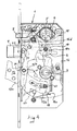
Figure 1 depicts a door lock according to an embodiment of the invention with the housing of the lock casing for the most part open and the parts of the lock in a so-called daytime use position, while the door is open; -
Figure 2 depicts the lock according toFigure 1 with the latch bolt deadlocked in its outermost protruding position, while the door is closed; -
Figure 3 depicts the lock according toFigure 2 in a situation, in which also the hook bolt is activated and protruded; -
Figure 4 depicts the lock according toFigure 3 after the protrusion of the hook bolt in a situation, in which also both the handle actuation and the turning knob actuation are prevented; -
Figure 5 depicts the lock according toFigure 4 in a situation, in which the lock members are activated for retracting the bolts; and -
Figure 6 depicts the lock according toFigure 5 after the bolts have been retracted and the door has been opened, while the handle is still pressed down. - In the drawings the
reference number 1 refers to a lock casing in a door lock comprising ahousing 1a and afront plate 2. The door itself is not shown. For handle actuation the lock casing is provided with afirst operating axis 3, on which afollower 4 is mounted (for the sake of clarity the handle itself is not shown) and asecond operating axis 5, on which afollower arrangement 6 is mounted for key actuation and turning knob actuation (neither the cylinder housing nor the turning knob are shown). Thefollower arrangement 6 comprises, in a manner known as such, two mutually independentturnable followers - The
lock casing 1 is provided with alatch bolt 7, which aspring 23 tends to push towards a protruding position and which has two protruding positions of different lengths. The choice between these two positions is made, in a way known as such, from the front plate's 2 side by a turnable selector member (not shown in detail) and in addition, the operation of thelatch bolt 7 is in a manner known as such controlled by anauxiliary bolt 8.Figure 1 illustrates the daytime use of the door lock after the door has been opened and arestraining member 9 in conjunction with theauxiliary bolt 8 has been moved by the selector member to a position, which in all situations and independently of theauxiliary bolt 8 prevents the movement of thelatch bolt 7 to its outermost protruding position. - For the retraction of the
latch bolt 7 aforce transmission piece 10 is turnably supported by it, on the pin 10a of which piece thefollower 4 acts. Aspring 11 acts on theforce transmission piece 10 tending to turn it anti-clockwise in the figures. Astationary pin 12 in the lock casing controls the movements of thelatch bolt 7. - In the situation according to
Figure 2 the selector member is moved to a position, in which it allows thelatch bolt 7 to move to its outermost protruding position. In this case the door is closed, whereby theauxiliary bolt 8 lies against a striker plate (not shown) in the doorframe only partly protruded. When the door is opened, theauxiliary bolt 8 is urged to its outer position according toFigure 1 and simultaneously presses therestraining member 9 to the position shown inFigure 1 . Then thelatch bolt 7 remains in its inner protruding position according toFigure 1 , whereby the door can be pressed closed, if required, without using the handle. All this is previously known technology. - In the situation according to
Figure 2 the door is closed and theforce transmission piece 10 is, urged by thespring 11, in a position, in which it is beyond reach of thefollower 4, whereby the force transmission connection from the operatingaxis 3 to thelatch bolt 7 is cut. In this position theforce transmission piece 10 provides also deadlocking of thelatch bolt 7 via thestationary pin 12 of the lock casing. This corresponds to the lighter safety locking mode of the door lock. When the aim in this situation is to open the door and retract thelatch bolt 7, the deadlocking of the latch bolt needs to be first disengaged and the force transmission connection to thelatch bolt 7 restored. For this purpose the lock casing is provided with a turnably supported activatingelement 18, which may be pressed against the force of thespring 11 by either follower, 6a or 6b, of the follower means 6 so that it moves theforce transmission piece 10 to a position, in which thelatch bolt 7 can by means of thefollower 4 be retracted inside the lock casing (cf.Figures 3 and5 ). - According to the invention it is also possible to select a heavier safety locking mode with other kind of safety qualities. For this purpose the
lock casing 1 also includes ahook bolt 13, known per se, comprisingparts pin 14. In addition, aforce transmission piece 15 is turnably supported by thepin 14. Further, the lock casing is for the activation of the use of thehook bolt 13 provided with an activatingpiece 16, which can be moved, urged by aspring 17, parallel to thefront plate 2 in the lock casing. The operation of these components will be explained in the following with special reference toFigures 3 - 6 , which depict the different phases of the operation related to the highest safety locking mode of the door lock. - The activating
piece 16 is provided with aprotrusion 16a, through which aspring 17 presses it upwards in the figures. ln the operating mode shown inFigures 1 and2 theprotrusion 16a acts also on thepart 13b of the hook bolt and prevents the movement of thehook bolt 13 to its protruding position. The activatingpiece 16 is also provided withcounter surfaces 16b (cf.Figure 1 ), which are in cooperation with thefollower arrangement 6 so that the activatingpiece 16 may by either follower, 6a or 6b, be pressed against the force of thespring 17, as shown inFigure 3 , and thus release thehook bolt 13 to be taken into use. - With reference to
Figure 3 , the activation of the use of thehook bolt 13 is performed by turning thefollower 4 of thefirst operating axis 3 in a direction opposite of the direction of normal handle operation, i.e. anti-clockwise in the figures, whereby it presses thehook bolt 13 to its protruding position according toFigure 3 by means of theforce transmission piece 15 turnably supported by thepin 14 of the hook bolt. For this purpose theforce transmission piece 15 is supported by astationary pin 19 of the lock casing. The control of the movements of thehook bolt 13 is carried out in a way known as such by utilising thepin 14 and a guide groove 1b in the lock casing, as well as aguide groove 13b' in the hook bolt'spart 13b and apin 20 in the lock casing. - The lock casing is also provided with a deadlocking
element 21 for the hook bolt turnably supported by thepin 20 of the lock casing, which element is provided with apin 21a and urged by aspring 22 towards the locking position of the deadlockingelement 21. ln the situation according toFigures 1 and2 theguide surface 16c in the activatingpiece 16 prevents, via thepin 21a, the movement of the deadlockingelement 21 to its locking position. On the other hand, the hook bolt'spart 13b acts simultaneously on theprotrusion 16a and prevents the movement of the activatingpiece 16 upwards in the figures. - After the
hook bolt 13 has been moved out and the follower means 6 turned from the position according toFigure 3 back to their normal position, the activatingelement 16 is allowed, urged by thespring 17, to move to the position according toFigure 4 , in which it is located higher up than in the positions according toFigures 1 and2 . Then, in the situation ofFigure 4 , the deadlockingelement 21 of thehook bolt 13 is first moved, urged by aspring 22, to its deadlocking position according toFigure 4 , in which itscounter surface 21b acts on thepin 14 of the hook bolt. Moreover, the activatingpiece 16 is provided with an actingmember 16d, by means of which the turning of the non-shown turning knob mounted on the operatingaxis 5 is prevented. The prevention may, in principle, occur directly or via a movable restraining member. The arrangement is, however, such that the key actuation may in any case provide, by means of thefollower arrangement 6, the movement of the activatingpiece 16, in a way shown inFigure 5 , back to the position, which corresponds to the position ofFigure 3 and which enables the retraction of thehook bolt 13 and enables the operation of the turning knob again. At the same time the follower means 6 press the activatingelement 18 to a position, in which the deadlocking of thelatch bolt 7 is disengaged and the force transmission from thefollower 4 is engaged. -
Figure 6 depicts the next phase, in which thebolts follower 4 is turned clockwise, it acts on the pin 10a of theforce transmission piece 10 and retracts thelatch bolt 7. The latch bolt is provided with apin 7a, which then hits theforce transmission piece 15 supported by thehook bolt 13 and retracts thus also thehook bolt 13 inside. Subsequently, after the follower means 6 have again been turned back to their normal position, the hook bolt'spart 13b prevents again the movement of the activatingpiece 16 to its activating position (cf.Figure 3 ). Similarly, theprotrusion 16a of the activating piece prevents the movement of thehook bolt 13 till the activatingpiece 16 is reactivated by the follower means 6 to allow the movement of the hook bolt 13 (cf.Figure 3 ). - Conclusively, the door lock according to the invention has three different operating modes. First, there is a mode for daytime use, in which only the latch bolt with its shorter protruding position is in use, whereby the door can be opened without a key. From this mode it is possible via the front plate to move, by turning a separate selector member, to a safety locking mode, in which the latch bolt can be moved to its outer protruding position, whereby it is also deadlocked. Then, the lock can be opened by a key from the outside of the door and by the turning knob from the inside of the door. From this mode it is possible, if so required, to move further to a secured safety locking mode, in which the hook bolt can be taken into use by the follower means mounted on the second operating axis by moving the special activating piece and in addition, to make the turning knob on the inside of the door inoperative. ln this situation the locking can always be disengaged from the outside of the door by a key. In order to make the disengagement of the locking possible also from the inside of the door, an additional key actuation independent of the turning of the turning knob is required.
- The invention is not limited to the shown embodiments, but several variations are conceivable within the scope of the appended claims.
Claims (11)
- A door lock comprising a lock casing (1) with a first operating axis (3) arranged for handle actuation and a first follower arrangement (4) mounted thereon, a second operating axis (5) arranged for key and/or turning knob actuation and a second follower arrangement (6) mounted thereon, a latch bolt (7) spring loaded to a position protruding from the lock casing, which latch bolt has two selectable protrusion positions of different lengths, an auxiliary bolt (8) for controlling the protrusion of the latch bolt (7), and a hook bolt (13), which may be positively urged to a protruding position and to a retracted position, the lock casing further being provided with activating means (16), which are selectively arranged so as to be moved from a first position, in which they prevent the protrusion of the hook bolt (13), to a second position in which they allow the protrusion of the hook bolt (13), wherein said activating means comprise an activating piece (16), one end of which is provided with a restraining member (16a) acting on the hook bolt (13) and the other end with a counter surface (16b), which is arranged in cooperation with the second follower arrangement (6) mounted on said second operating axis (5) for moving the activating piece (16) from said first position to said second position.
- A door lock according to claim 1, characterised in that the activating piece (16) is spring-loaded (17) towards its first position.
- A door lock according to claim 1 or 2. characterised in that the lock casing (1) is provided with a deadlocking element (21) for the hook bolt (13), which element is turnably supported by the lock casing and spring-loaded (22) towards its deadlocking position, and that the activating piece (16) is arranged to control the movements of the deadlocking element (21) so that it allows the movement of the deadlocking element (21) to its deadlocking position, while the hook bolt (13) is in its protruding position.
- A door lock according to anyone of the preceding claims, characterised in that the activating piece (16) is movable to a third position, in which it is arranged to prevent the turning of the turning knob means mounted on said second operating axis (5).
- A door lock according to claim 4, characterised in that said second and third positions of the activating piece (16) are on different sides of said first position, and that the hook bolt (13; 13b) is arranged to prevent the movement of the activating piece (16) to its said third position, while the hook bolt (13) is in its retracted position.
- A door lock according to anyone of the preceding claims, characterised in that the retraction of the latch bolt (7) is arranged to be accomplished by said follower means (4) mounted on the first operating axis (3), and that the movement of the hook bolt (13) to its protruding position is arranged to be accomplished by said follower means (4) by turning them in an opposite direction with respect to the direction of the retraction of the latch bolt.
- A door lock according to claim 6, characterised in that the hook bolt (13) is provided with a force transmission piece (15) turnably supported by it, on which piece said follower means (4) are arranged to act for protruding the hook bolt (13) and on which the latch bolt (7) is arranged to act for retracting the hook bolt (13).
- A door lock according to anyone of the preceding claims, characterised in that the latch bolt (7) and the hook bolt (13) are arranged to be retracted inside the lock casing (1) only by said follower means (4) mounted on the first operating axis (3), and that the larch bolt (7) is provided with a force transmission piece (10) turnably supported by it.
- A door lock according to claim 8, characterised in that said force transmission piece (10) is spring-loaded (11) towards a first position, in which it is beyond reach of said first follower means (4) and from which it can be moved to a second position, in which it is in cooperation with said follower means (4) for retracting the bolts (7, 13).
- A door lock according to claim 9, characterised in that said force transmission piece (10) is in its said first position arranged to deadlock the latch bolt (7).
- A door lock according to anyone of claims 8 - 10, characterised in that said second follower means (6) mounted on the second operating axis (5) are arranged to control the movements of said force transmission piece (10).
Applications Claiming Priority (1)
| Application Number | Priority Date | Filing Date | Title |
|---|---|---|---|
| FI20065199A FI121344B (en) | 2006-03-28 | 2006-03-28 | Locks |
Publications (3)
| Publication Number | Publication Date |
|---|---|
| EP1840302A2 EP1840302A2 (en) | 2007-10-03 |
| EP1840302A3 EP1840302A3 (en) | 2009-04-01 |
| EP1840302B1 true EP1840302B1 (en) | 2011-09-21 |
Family
ID=36192044
Family Applications (1)
| Application Number | Title | Priority Date | Filing Date |
|---|---|---|---|
| EP07103777A Active EP1840302B1 (en) | 2006-03-28 | 2007-03-08 | Door lock |
Country Status (3)
| Country | Link |
|---|---|
| EP (1) | EP1840302B1 (en) |
| AT (1) | ATE525544T1 (en) |
| FI (1) | FI121344B (en) |
Cited By (1)
| Publication number | Priority date | Publication date | Assignee | Title |
|---|---|---|---|---|
| WO2014018214A1 (en) * | 2012-07-25 | 2014-01-30 | Schlage Lock Company Llc | Privacy override function for a door lock |
Families Citing this family (10)
| Publication number | Priority date | Publication date | Assignee | Title |
|---|---|---|---|---|
| SE532298C2 (en) * | 2008-04-16 | 2009-12-08 | Jokab Safety Ab | Locking |
| IT1394394B1 (en) * | 2008-08-06 | 2012-06-15 | Iseo Serrature Spa | LOCK WITH MULTIPLE CLOSING POINTS |
| DE102010005926A1 (en) * | 2009-06-03 | 2010-12-09 | Dorma Gmbh + Co. Kg | Lock, in particular door lock, with improved locking mechanism |
| SE1050260A1 (en) * | 2010-03-19 | 2011-02-01 | Assa Oem Ab | Locking device with adjustable locking device |
| CN102003120B (en) * | 2010-11-30 | 2012-11-14 | 中山亚萨合莱安防科技有限公司 | Self-touch door lock |
| CN103806761B (en) * | 2012-11-07 | 2016-05-11 | 王力安防产品有限公司 | A kind of locking device for door-lock |
| CN104100146B (en) * | 2013-04-02 | 2017-03-01 | 王力安防产品有限公司 | Double-key-unlocked lock controlling organization |
| CN103306550B (en) * | 2013-07-02 | 2015-03-25 | 黄辉源 | False mortise single-hook movable door lock |
| DE102014104129A1 (en) * | 2014-03-25 | 2015-10-01 | Assa Abloy Nederland B.V. | Lock for door or window |
| GB201707144D0 (en) | 2017-05-04 | 2017-06-21 | Era Home Security Ltd | Locking assembly |
Family Cites Families (4)
| Publication number | Priority date | Publication date | Assignee | Title |
|---|---|---|---|---|
| EP0677132A4 (en) * | 1993-10-06 | 1996-12-18 | Ladislav Stephan Karpisek | Improvements in universal locks. |
| DE19848865A1 (en) * | 1998-10-23 | 2000-04-27 | Fliether Karl Gmbh & Co | Lock, especially espagnolette lock |
| SE521128C2 (en) * | 2002-03-15 | 2003-09-30 | Assa Ab | Locking device with knob lock |
| ES2211277B1 (en) * | 2002-04-10 | 2005-10-01 | La Industrial Cerrajera, S.A. | SECURITY LOCK WITH DOUBLE CONTROL OF THE PICAPORTE AND ANTIPANIC FUNCTION. |
-
2006
- 2006-03-28 FI FI20065199A patent/FI121344B/en active IP Right Grant
-
2007
- 2007-03-08 AT AT07103777T patent/ATE525544T1/en not_active IP Right Cessation
- 2007-03-08 EP EP07103777A patent/EP1840302B1/en active Active
Cited By (2)
| Publication number | Priority date | Publication date | Assignee | Title |
|---|---|---|---|---|
| WO2014018214A1 (en) * | 2012-07-25 | 2014-01-30 | Schlage Lock Company Llc | Privacy override function for a door lock |
| US8997534B2 (en) | 2012-07-25 | 2015-04-07 | Schlage Lock Company Llc | Privacy override function for a door lock |
Also Published As
| Publication number | Publication date |
|---|---|
| EP1840302A2 (en) | 2007-10-03 |
| FI20065199A (en) | 2007-09-29 |
| FI121344B (en) | 2010-10-15 |
| EP1840302A3 (en) | 2009-04-01 |
| ATE525544T1 (en) | 2011-10-15 |
| FI20065199A0 (en) | 2006-03-28 |
Similar Documents
| Publication | Publication Date | Title |
|---|---|---|
| EP1840302B1 (en) | Door lock | |
| US11572722B2 (en) | Multiple point door locking system | |
| EP1793070B1 (en) | Operating device of a door latch in a vehicle | |
| US4583382A (en) | Reversible latch assembly with integrated function | |
| US6343817B1 (en) | Vehicle door latch device with double action mechanism | |
| US7677067B2 (en) | Lock | |
| CN108252586B (en) | Double-latch lockset | |
| US20100213724A1 (en) | Multiple point door locking system, with handle turning direction control | |
| US20080156049A1 (en) | Multipoint door/window lock with panic override | |
| JP4538001B2 (en) | Guide structure of latch bolt locking in door lock | |
| US20040066046A1 (en) | Multipoint lock system | |
| CN108252574B (en) | Sliding actuator assembly for a lock | |
| WO2007000763A1 (en) | Mortise lock | |
| US6131966A (en) | Latch holdback mechanism for a mortise lock | |
| AU2005238548B2 (en) | Locks | |
| KR200423328Y1 (en) | The device of panic motise and working methode | |
| RU2731429C2 (en) | Rebated door lock | |
| EP1899560B1 (en) | Lock for internal door | |
| US10968662B2 (en) | Dual lock system | |
| CA3026702C (en) | Hook bolt for door lock | |
| EP1840303A2 (en) | Auxiliary bolt arrangement in a door lock | |
| WO2002066774A1 (en) | Control arrangement for a latch bolt in a door lock | |
| EP2171187B1 (en) | Lock for reinforced doors and the like comprising a selector | |
| KR200378846Y1 (en) | Mortise in a door lock | |
| EP3252252B1 (en) | Lock with dead bolt and latch bolt |
Legal Events
| Date | Code | Title | Description |
|---|---|---|---|
| PUAI | Public reference made under article 153(3) epc to a published international application that has entered the european phase |
Free format text: ORIGINAL CODE: 0009012 |
|
| AK | Designated contracting states |
Kind code of ref document: A2 Designated state(s): AT BE BG CH CY CZ DE DK EE ES FI FR GB GR HU IE IS IT LI LT LU LV MC MT NL PL PT RO SE SI SK TR |
|
| AX | Request for extension of the european patent |
Extension state: AL BA HR MK YU |
|
| PUAL | Search report despatched |
Free format text: ORIGINAL CODE: 0009013 |
|
| AK | Designated contracting states |
Kind code of ref document: A3 Designated state(s): AT BE BG CH CY CZ DE DK EE ES FI FR GB GR HU IE IS IT LI LT LU LV MC MT NL PL PT RO SE SI SK TR |
|
| AX | Request for extension of the european patent |
Extension state: AL BA HR MK RS |
|
| 17P | Request for examination filed |
Effective date: 20090925 |
|
| AKX | Designation fees paid |
Designated state(s): AT BE BG CH CY CZ DE DK EE ES FI FR GB GR HU IE IS IT LI LT LU LV MC MT NL PL PT RO SE SI SK TR |
|
| GRAP | Despatch of communication of intention to grant a patent |
Free format text: ORIGINAL CODE: EPIDOSNIGR1 |
|
| GRAS | Grant fee paid |
Free format text: ORIGINAL CODE: EPIDOSNIGR3 |
|
| GRAA | (expected) grant |
Free format text: ORIGINAL CODE: 0009210 |
|
| AK | Designated contracting states |
Kind code of ref document: B1 Designated state(s): AT BE BG CH CY CZ DE DK EE ES FI FR GB GR HU IE IS IT LI LT LU LV MC MT NL PL PT RO SE SI SK TR |
|
| REG | Reference to a national code |
Ref country code: GB Ref legal event code: FG4D |
|
| REG | Reference to a national code |
Ref country code: CH Ref legal event code: EP |
|
| REG | Reference to a national code |
Ref country code: IE Ref legal event code: FG4D |
|
| REG | Reference to a national code |
Ref country code: DE Ref legal event code: R096 Ref document number: 602007017313 Country of ref document: DE Effective date: 20111201 |
|
| REG | Reference to a national code |
Ref country code: SE Ref legal event code: TRGR |
|
| REG | Reference to a national code |
Ref country code: NL Ref legal event code: VDEP Effective date: 20110921 |
|
| PG25 | Lapsed in a contracting state [announced via postgrant information from national office to epo] |
Ref country code: FI Free format text: LAPSE BECAUSE OF FAILURE TO SUBMIT A TRANSLATION OF THE DESCRIPTION OR TO PAY THE FEE WITHIN THE PRESCRIBED TIME-LIMIT Effective date: 20110921 Ref country code: LT Free format text: LAPSE BECAUSE OF FAILURE TO SUBMIT A TRANSLATION OF THE DESCRIPTION OR TO PAY THE FEE WITHIN THE PRESCRIBED TIME-LIMIT Effective date: 20110921 |
|
| REG | Reference to a national code |
Ref country code: EE Ref legal event code: FG4A Ref document number: E006188 Country of ref document: EE Effective date: 20111128 |
|
| LTIE | Lt: invalidation of european patent or patent extension |
Effective date: 20110921 |
|
| PG25 | Lapsed in a contracting state [announced via postgrant information from national office to epo] |
Ref country code: GR Free format text: LAPSE BECAUSE OF FAILURE TO SUBMIT A TRANSLATION OF THE DESCRIPTION OR TO PAY THE FEE WITHIN THE PRESCRIBED TIME-LIMIT Effective date: 20111222 Ref country code: AT Free format text: LAPSE BECAUSE OF FAILURE TO SUBMIT A TRANSLATION OF THE DESCRIPTION OR TO PAY THE FEE WITHIN THE PRESCRIBED TIME-LIMIT Effective date: 20110921 Ref country code: LV Free format text: LAPSE BECAUSE OF FAILURE TO SUBMIT A TRANSLATION OF THE DESCRIPTION OR TO PAY THE FEE WITHIN THE PRESCRIBED TIME-LIMIT Effective date: 20110921 Ref country code: SI Free format text: LAPSE BECAUSE OF FAILURE TO SUBMIT A TRANSLATION OF THE DESCRIPTION OR TO PAY THE FEE WITHIN THE PRESCRIBED TIME-LIMIT Effective date: 20110921 Ref country code: CY Free format text: LAPSE BECAUSE OF FAILURE TO SUBMIT A TRANSLATION OF THE DESCRIPTION OR TO PAY THE FEE WITHIN THE PRESCRIBED TIME-LIMIT Effective date: 20110921 |
|
| REG | Reference to a national code |
Ref country code: AT Ref legal event code: MK05 Ref document number: 525544 Country of ref document: AT Kind code of ref document: T Effective date: 20110921 |
|
| PG25 | Lapsed in a contracting state [announced via postgrant information from national office to epo] |
Ref country code: BE Free format text: LAPSE BECAUSE OF FAILURE TO SUBMIT A TRANSLATION OF THE DESCRIPTION OR TO PAY THE FEE WITHIN THE PRESCRIBED TIME-LIMIT Effective date: 20110921 |
|
| PG25 | Lapsed in a contracting state [announced via postgrant information from national office to epo] |
Ref country code: SK Free format text: LAPSE BECAUSE OF FAILURE TO SUBMIT A TRANSLATION OF THE DESCRIPTION OR TO PAY THE FEE WITHIN THE PRESCRIBED TIME-LIMIT Effective date: 20110921 Ref country code: IS Free format text: LAPSE BECAUSE OF FAILURE TO SUBMIT A TRANSLATION OF THE DESCRIPTION OR TO PAY THE FEE WITHIN THE PRESCRIBED TIME-LIMIT Effective date: 20120121 Ref country code: CZ Free format text: LAPSE BECAUSE OF FAILURE TO SUBMIT A TRANSLATION OF THE DESCRIPTION OR TO PAY THE FEE WITHIN THE PRESCRIBED TIME-LIMIT Effective date: 20110921 |
|
| PG25 | Lapsed in a contracting state [announced via postgrant information from national office to epo] |
Ref country code: PL Free format text: LAPSE BECAUSE OF FAILURE TO SUBMIT A TRANSLATION OF THE DESCRIPTION OR TO PAY THE FEE WITHIN THE PRESCRIBED TIME-LIMIT Effective date: 20110921 Ref country code: IT Free format text: LAPSE BECAUSE OF FAILURE TO SUBMIT A TRANSLATION OF THE DESCRIPTION OR TO PAY THE FEE WITHIN THE PRESCRIBED TIME-LIMIT Effective date: 20110921 Ref country code: NL Free format text: LAPSE BECAUSE OF FAILURE TO SUBMIT A TRANSLATION OF THE DESCRIPTION OR TO PAY THE FEE WITHIN THE PRESCRIBED TIME-LIMIT Effective date: 20110921 Ref country code: RO Free format text: LAPSE BECAUSE OF FAILURE TO SUBMIT A TRANSLATION OF THE DESCRIPTION OR TO PAY THE FEE WITHIN THE PRESCRIBED TIME-LIMIT Effective date: 20110921 Ref country code: PT Free format text: LAPSE BECAUSE OF FAILURE TO SUBMIT A TRANSLATION OF THE DESCRIPTION OR TO PAY THE FEE WITHIN THE PRESCRIBED TIME-LIMIT Effective date: 20120123 |
|
| PLBE | No opposition filed within time limit |
Free format text: ORIGINAL CODE: 0009261 |
|
| STAA | Information on the status of an ep patent application or granted ep patent |
Free format text: STATUS: NO OPPOSITION FILED WITHIN TIME LIMIT |
|
| PG25 | Lapsed in a contracting state [announced via postgrant information from national office to epo] |
Ref country code: DK Free format text: LAPSE BECAUSE OF FAILURE TO SUBMIT A TRANSLATION OF THE DESCRIPTION OR TO PAY THE FEE WITHIN THE PRESCRIBED TIME-LIMIT Effective date: 20110921 |
|
| 26N | No opposition filed |
Effective date: 20120622 |
|
| REG | Reference to a national code |
Ref country code: DE Ref legal event code: R097 Ref document number: 602007017313 Country of ref document: DE Effective date: 20120622 |
|
| PG25 | Lapsed in a contracting state [announced via postgrant information from national office to epo] |
Ref country code: MC Free format text: LAPSE BECAUSE OF NON-PAYMENT OF DUE FEES Effective date: 20120331 |
|
| REG | Reference to a national code |
Ref country code: CH Ref legal event code: PL |
|
| GBPC | Gb: european patent ceased through non-payment of renewal fee |
Effective date: 20120308 |
|
| REG | Reference to a national code |
Ref country code: FR Ref legal event code: ST Effective date: 20121130 |
|
| REG | Reference to a national code |
Ref country code: IE Ref legal event code: MM4A |
|
| REG | Reference to a national code |
Ref country code: DE Ref legal event code: R119 Ref document number: 602007017313 Country of ref document: DE Effective date: 20121002 |
|
| PG25 | Lapsed in a contracting state [announced via postgrant information from national office to epo] |
Ref country code: IE Free format text: LAPSE BECAUSE OF NON-PAYMENT OF DUE FEES Effective date: 20120308 Ref country code: LI Free format text: LAPSE BECAUSE OF NON-PAYMENT OF DUE FEES Effective date: 20120331 Ref country code: CH Free format text: LAPSE BECAUSE OF NON-PAYMENT OF DUE FEES Effective date: 20120331 Ref country code: GB Free format text: LAPSE BECAUSE OF NON-PAYMENT OF DUE FEES Effective date: 20120308 Ref country code: FR Free format text: LAPSE BECAUSE OF NON-PAYMENT OF DUE FEES Effective date: 20120402 |
|
| PG25 | Lapsed in a contracting state [announced via postgrant information from national office to epo] |
Ref country code: ES Free format text: LAPSE BECAUSE OF FAILURE TO SUBMIT A TRANSLATION OF THE DESCRIPTION OR TO PAY THE FEE WITHIN THE PRESCRIBED TIME-LIMIT Effective date: 20120101 |
|
| PG25 | Lapsed in a contracting state [announced via postgrant information from national office to epo] |
Ref country code: BG Free format text: LAPSE BECAUSE OF FAILURE TO SUBMIT A TRANSLATION OF THE DESCRIPTION OR TO PAY THE FEE WITHIN THE PRESCRIBED TIME-LIMIT Effective date: 20111221 |
|
| PG25 | Lapsed in a contracting state [announced via postgrant information from national office to epo] |
Ref country code: MT Free format text: LAPSE BECAUSE OF FAILURE TO SUBMIT A TRANSLATION OF THE DESCRIPTION OR TO PAY THE FEE WITHIN THE PRESCRIBED TIME-LIMIT Effective date: 20110921 |
|
| PG25 | Lapsed in a contracting state [announced via postgrant information from national office to epo] |
Ref country code: TR Free format text: LAPSE BECAUSE OF FAILURE TO SUBMIT A TRANSLATION OF THE DESCRIPTION OR TO PAY THE FEE WITHIN THE PRESCRIBED TIME-LIMIT Effective date: 20110921 |
|
| PG25 | Lapsed in a contracting state [announced via postgrant information from national office to epo] |
Ref country code: LU Free format text: LAPSE BECAUSE OF NON-PAYMENT OF DUE FEES Effective date: 20120308 |
|
| PG25 | Lapsed in a contracting state [announced via postgrant information from national office to epo] |
Ref country code: HU Free format text: LAPSE BECAUSE OF FAILURE TO SUBMIT A TRANSLATION OF THE DESCRIPTION OR TO PAY THE FEE WITHIN THE PRESCRIBED TIME-LIMIT Effective date: 20070308 |
|
| PG25 | Lapsed in a contracting state [announced via postgrant information from national office to epo] |
Ref country code: DE Free format text: LAPSE BECAUSE OF FAILURE TO SUBMIT A TRANSLATION OF THE DESCRIPTION OR TO PAY THE FEE WITHIN THE PRESCRIBED TIME-LIMIT Effective date: 20121002 |
|
| PGFP | Annual fee paid to national office [announced via postgrant information from national office to epo] |
Ref country code: SE Payment date: 20230210 Year of fee payment: 17 Ref country code: EE Payment date: 20230221 Year of fee payment: 17 |