EP1840282B1 - Vacuum sewer system - Google Patents
Vacuum sewer system Download PDFInfo
- Publication number
- EP1840282B1 EP1840282B1 EP20070101944 EP07101944A EP1840282B1 EP 1840282 B1 EP1840282 B1 EP 1840282B1 EP 20070101944 EP20070101944 EP 20070101944 EP 07101944 A EP07101944 A EP 07101944A EP 1840282 B1 EP1840282 B1 EP 1840282B1
- Authority
- EP
- European Patent Office
- Prior art keywords
- discharge valve
- valve
- aeration means
- vacuum
- aeration
- Prior art date
- Legal status (The legal status is an assumption and is not a legal conclusion. Google has not performed a legal analysis and makes no representation as to the accuracy of the status listed.)
- Active
Links
- 238000005273 aeration Methods 0.000 claims description 129
- 230000007246 mechanism Effects 0.000 claims description 76
- 239000010865 sewage Substances 0.000 claims description 34
- 238000011010 flushing procedure Methods 0.000 claims description 24
- 239000012530 fluid Substances 0.000 claims description 3
- XLYOFNOQVPJJNP-UHFFFAOYSA-N water Substances O XLYOFNOQVPJJNP-UHFFFAOYSA-N 0.000 description 10
- 230000003213 activating effect Effects 0.000 description 6
- 230000001419 dependent effect Effects 0.000 description 2
- 230000000694 effects Effects 0.000 description 2
- 239000010866 blackwater Substances 0.000 description 1
- 238000005352 clarification Methods 0.000 description 1
- 239000010797 grey water Substances 0.000 description 1
Images

Classifications
-
- E—FIXED CONSTRUCTIONS
- E03—WATER SUPPLY; SEWERAGE
- E03F—SEWERS; CESSPOOLS
- E03F1/00—Methods, systems, or installations for draining-off sewage or storm water
- E03F1/006—Pneumatic sewage disposal systems; accessories specially adapted therefore
-
- E—FIXED CONSTRUCTIONS
- E03—WATER SUPPLY; SEWERAGE
- E03D—WATER-CLOSETS OR URINALS WITH FLUSHING DEVICES; FLUSHING VALVES THEREFOR
- E03D11/00—Other component parts of water-closets, e.g. noise-reducing means in the flushing system, flushing pipes mounted in the bowl, seals for the bowl outlet, devices preventing overflow of the bowl contents; devices forming a water seal in the bowl after flushing, devices eliminating obstructions in the bowl outlet or preventing backflow of water and excrements from the waterpipe
-
- E—FIXED CONSTRUCTIONS
- E03—WATER SUPPLY; SEWERAGE
- E03D—WATER-CLOSETS OR URINALS WITH FLUSHING DEVICES; FLUSHING VALVES THEREFOR
- E03D5/00—Special constructions of flushing devices, e.g. closed flushing system
- E03D5/02—Special constructions of flushing devices, e.g. closed flushing system operated mechanically or hydraulically (or pneumatically) also details such as push buttons, levers and pull-card therefor
- E03D5/024—Operated hydraulically or pneumatically
-
- E—FIXED CONSTRUCTIONS
- E03—WATER SUPPLY; SEWERAGE
- E03D—WATER-CLOSETS OR URINALS WITH FLUSHING DEVICES; FLUSHING VALVES THEREFOR
- E03D9/00—Sanitary or other accessories for lavatories ; Devices for cleaning or disinfecting the toilet room or the toilet bowl; Devices for eliminating smells
- E03D9/14—Noise-reducing means combined with flushing valves
-
- E—FIXED CONSTRUCTIONS
- E03—WATER SUPPLY; SEWERAGE
- E03F—SEWERS; CESSPOOLS
- E03F1/00—Methods, systems, or installations for draining-off sewage or storm water
Definitions
- the present invention relates to a discharge valve including an aeration means for a vacuum sewer system comprising a sewage receptacle, sewer piping, a vacuum generating means for generating vacuum in the sewer piping, and a control mechanism, which discharge valve including the aeration means is arranged to be installed between the sewage receptacle and the sewer piping and is controlled by the control mechanism, according to the preamble of claim 1.
- the sewage receptacle may be e.g. a toilet unit or toilet bowl, urinal, sink, wash basin, shower, etc.
- the sewage may be black water originating from e.g. a toilet unit or a urinal, or grey water originating from e.g. a sink, wash basin, shower, etc.
- a rinse water arrangement may be deployed depending upon the source of sewage.
- Vacuum for the control mechanism is often taken at a point of the sewer piping adjacent the discharge valve in the flow direction of the sewage.
- the discharge valve is opened, the vacuum level is lowered due to atmospheric air entering the sewer piping.
- the control mechanism functions like a three-way valve, whereby the closing of the discharge valve takes place by aeration of the same by way of the control mechanism. Consequently, the closing speed is dependent on the flow resistance of the aeration conduit.
- vacuum arrangements are known e.g. from GB 2 149 534 A .
- An object of the present invention is to achieve a discharge valve including an aeration means the noise level of which during a discharge or flushing sequence is lowered.
- a further object of the present invention is to provide a discharge valve, which improves the operation of the vacuum sewer system.
- the basic idea of the invention is to provide the discharge valve including the aeration means with a so-called rapid vent valve that provides for an effective and rapid closing of the discharge valve after discharge of the sewage from the sewage receptacle, which also results in a lower noise level.
- the effective and rapid closing of the discharge valve is achieved by a direct supply of supplementary air to the discharge valve.
- the discharge valve includes an aeration means, which is arranged to provide a direct fluid communication to the discharge valve.
- the control mechanism controls the discharge valve including the aeration means.
- the aeration means is arranged to supply air to the discharge valve for rapidly closing the discharge valve after a discharge or flushing sequence.
- the aeration means is arranged to be closed when the discharge valve is provided with vacuum for opening the same for the discharge or flushing sequence. In this way, the aeration means affects the closure time, but does not interfere with the opening of the discharge valve.
- Such an aeration means may advantageously be pneumatically or electrically governed.
- the aeration means advantageously comprises a vent valve, which is attached to the discharge valve and connected to the control mechanism by means of a fourth conduit. This arrangement provides for direct and rapid aeration of the discharge valve at its closing phase and may be governed by the control mechanism through the fourth conduit.
- the aeration means is advantageously provided with an aeration nozzle for closing the aeration means with a given delay after the discharge or flushing sequence.
- the aeration means may also comprise a vent valve, which is arranged in connection with the discharge valve and connected to the control mechanism by means of a fourth conduit, whereby a fifth conduit is provided between the aeration means and the discharge valve.
- a vent valve which is arranged in connection with the discharge valve and connected to the control mechanism by means of a fourth conduit, whereby a fifth conduit is provided between the aeration means and the discharge valve.
- This arrangement provides for direct and rapid aeration of the discharge valve at its closing phase.
- the aeration means may be attached to the discharge valve or arranged separately of the discharge valve.
- the opening and closing function of the aeration means may be governed by the control mechanism in series with the discharge valve.
- the function of the aeration means may advantageously also be electrically governed.
- the aeration means comprises a vent valve, which is attached to the discharge valve, whereby the control mechanism is arranged to control the aeration means by way of a sensor device and a magnetic valve connected to the aeration means.
- This arrangement provides for direct and rapid aeration of the discharge valve at its closing phase.
- the sensor device is advantageously connected to the control means for reading, if the vacuum connection to the discharge valve is switched on or off, and to correspondingly close or open the aeration means.
- the above provides easy and reliable ways to govern the function of the aeration means based on the vacuum control of the discharge valve provided by the control mechanism.
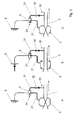
- Fig. 1 illustrates in a general manner an embodiment of a vacuum sewer system comprising a sewage receptacle 1, sewer piping 3 connected to the sewage receptacle 1 by means of a discharge valve 2, and a vacuum generating means 4 for generating vacuum in the sewer piping 3.
- the vacuum sewer system is provided with a control mechanism 5 for controlling the function of the discharge valve 2.
- the vacuum sewer system may include a plurality of sewage receptacles with related discharge valves, (water valves), and control mechanisms, whereby the number of vacuum generating means may vary depending upon the layout and size of the whole system.
- Vacuum sewer systems including vacuum operated discharge valves, vacuum operated water valves, and vacuum control mechanisms, are well known in the art and are not therefore explained in further detail in this connection.
- the vacuum control mechanism 5 is connected to the sewer piping 3, at a point 33 adjacent the discharge valve 2 in the flow direction (indicated by an arrow) of the sewage, by means of a first conduit 31 and through a check valve 32.
- the control mechanism 5 is connected to the vacuum operated discharge valve 2 by means of a second conduit 21.
- the control mechanism 5 is also provided with an activating means 6, such as a push button or an infrared trigger device, for activating the control mechanism 5 in order to initiate a flushing or discharge sequence.
- the sewage receptacle 1 is shown as a toilet bowl also provided with a rinse water arrangement comprising a water supply 7, a vacuum operated water valve 8 and a rinse water nozzle 9 in connection with the toilet bowl.
- the control mechanism 5 also governs the function of the water valve 8 and is connected thereto by means of a third conduit 81.
- the sewage receptacle may also be a urinal, sink, washbasin, shower, etc. as discussed above.
- the rinse water arrangement is optional and its use is dependent of the type of sewage receptacle.
- Fig. 1 also shows in a general manner that the vacuum sewer system is provided with an aeration means 10, in this embodiment in the form of a rapid vent valve, which is in fluid communication with the discharge valve 2 and the control mechanism 5 (by means of a fourth conduit 11).
- the purpose of the aeration means 10 is to accelerate or speed up the closing of the discharge valve 2, whereby its function is controlled by the control mechanism 5. This will be discussed in more detail in connections with Figs. 3 , 4 and 5 below.
- each sewage receptacle is provided with a discharge valve, to which the aeration means is connected.
- a vacuum sewer system usually comprises one or more, or even a plurality of sewage receptacles, the number of discharge valves and thereto connected aeration means in a system vary accordingly.
- the discharge valves including the aeration means may separately be installed or replaced in connection with service, repair, or e.g. enlarging the vacuum sewer system.
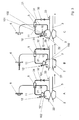
- Fig. 2 illustrates the discharge or flushing sequence usually employed in connection with vacuum sewer systems as discussed above.
- the function of the vacuum sewer system is usually based on vacuum present in the sewer piping 3.
- the control unit 5 directs or supplies vacuum to the discharge valve 2 (and the water valve 8, Fig. 1 ) for opening the same.
- the control mechanism 5 generally functions like a three-way valve, whereby also aeration of the discharge valve 2 takes place through the control mechanism 5 by a switch of the three-way valve position.
- vacuum is connected to the control mechanism 5 for governing the function of the discharge valve 2.
- Vacuum is tapped at point 33 of the sewer piping 3, adjacent and downstream of the discharge valve 2, and led through the check valve 32 and the first conduit 31 to the control mechanism 5.
- the discharge valve 2 is aerated through the second conduit 21 and an aeration valve 51 in the control mechanism 5.
- the control mechanism 5 is activated (indicated by a black arrow) by the activating means 6. This switches the three-way valve position and establishes a contact between the second conduit 21 and the vacuum available in the control mechanism 5 through the first conduit 31. Vacuum is thus connected to the discharge valve 2 for opening the same, whereby sewage collected in the sewage receptacle 1 ( Fig. 1 ) is discharged (direction of sewage flow indicated by arrow) as the discharge valve 2 is opened.
- control mechanism 5 closes said contact, by switching the three-way valve position, and re-establishes contact between the second conduit 21 and the aeration valve 51 (corresponding to the stand-by mode A), whereby the discharge valve 2 is aerated and consequently closed (aeration mode C).
- the vacuum sewer system is then ready for a new discharge or flushing sequence.
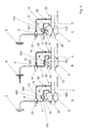
- Fig. 3 shows a first embodiment of the present invention.
- the function of the vacuum sewer system is based on vacuum present in the sewer piping 3.
- the control mechanism 5 directs or supplies vacuum to the discharge valve 2 for opening the same.
- the control mechanism 5 generally functions like a three-way valve.
- the vacuum sewer system comprises an aeration means 10, which is directly attached to the discharge valve 2 and connected to the control mechanism 5 by means of a fourth conduit 11.
- the aeration means 10 is in the form of a vent valve, or rapid vent valve and its purpose is to rapidly ventilate, i.e. provide air directly to the vacuum operated discharge valve 2 for the closing of the same.
- the aeration means 10 comprises an expandable chamber 101 with a valve plate 102 arranged to open or close against a valve seat 22 in the discharge valve 2.
- the aeration means 10 is provided with an aeration nozzle 12.
- the aeration means is pneumatically governed, by air/vacuum.
- a stand-by mode vacuum is connected to the control mechanism 5. Vacuum is tapped at point 33, adjacent and downstream of the discharge valve 2, of the sewer piping 3 and led through the check valve 32 and the first conduit 31 to the control mechanism 5.
- the discharge valve 2 is aerated through the aeration nozzle 12 of the aeration means 10 through the fourth conduit 11 connecting by way of the control mechanism 5 to the second conduit 21 leading to the discharge valve 2.
- the aeration means 10 is closed, being aerated through the aeration nozzle 12, with respect to the discharge valve 2 in this stand-by mode A. This is illustrated by the valve plate 102 being closed against the valve seat 22 in the discharge valve 2.
- the control mechanism 5 is activated (indicated by a black arrow) by the activating means 6. This switches the three-way valve position and establishes a contact between the second conduit 21 and the vacuum available in the control mechanism 5 through the first conduit 31. Vacuum is thus connected to the discharge valve 2 for opening the same, whereby sewage collected in the sewage receptacle 1 ( Fig. 1 ) is discharged (direction of sewage flow indicated by arrow) as the discharge valve 2 is opened.
- the control mechanism 5 closes the connection to the fourth conduit 11 and the aeration means 10 remains closed and aerated through the aeration nozzle 12.
- the control mechanism 5 closes the vacuum connection by switching the three-way valve position and re-establishes contact between the second conduit 21 and the fourth conduit 11 connected to the aeration means 10. This switching connects the vacuum in the discharge valve 2 by way of the second conduit 21 through the control means 5 and further through the fourth conduit 11 to the aeration means 10, whereby the aeration means 10 is opened.
- the vacuum contracts the expandable chamber 101 of the aeration means 10, whereby the valve plate 102 is withdrawn from the valve seat 22 in the discharge valve 2.
- the discharge valve 2 receives air (indicated by a double-ended arrow) directly through first openings 13 and the open valve seat 22 and is rapidly closed (aeration mode C).
- the aeration means 10 is aerated through the aeration nozzle 12 and closes with a given delay (depending on the dimensioning of the aeration nozzle 12).
- the aeration means 10 provides a rapid closure of the discharge valve 2 with the advantages discussed above.
- the vacuum sewer system is then ready for a new discharge or flushing sequence.
- Rapid aeration of the discharge valve may be provided in many ways. An alternative arrangement will be discussed in connection with Fig. 4 as follows.
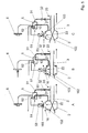
- Fig. 4 shows a second embodiment of the present invention.
- the function of the vacuum sewer system is based on vacuum present in the sewer piping 3.
- the control mechanism 5 directs or supplies vacuum to the discharge valve 2 for opening the same.
- the control mechanism 5 generally functions like a three-way valve.
- the vacuum sewer system comprises an aeration means 10, which is in connection with the discharge valve 2 and connected to the control means 5 by means of a fourth conduit 11.
- the aeration means 10 is in the form of a vent valve, or rapid vent valve and its purpose is to rapidly ventilate, i.e. provide air directly to the vacuum operated discharge valve 2 for the closing of the same.
- the aeration means 10 comprises an expandable chamber 101 with an internal spring means 104 and a valve stem 103 with a valve plate 102, which is arranged to open or close against a valve seat 22 in the discharge valve 2.
- the aeration means is pneumatically governed, by air/vacuum.
- the vacuum connection from the control mechanism 5 to the discharge valve 2 passes through the aeration means 10, whereby the fourth conduit 11 provides the connection between the control mechanism 5 and the aeration means 2 and a fifth conduit 14 provides a connection between the aeration means 10 and the discharge valve 2.
- a stand-by mode vacuum is connected to the control mechanism 5. Vacuum is tapped at point 33, adjacent and downstream of the discharge valve 2, of the sewer piping 3 and led through the check valve 32 and the first conduit 31 to the control mechanism 5.
- the discharge valve 2 is aerated through second openings 15.
- the aeration means 10 is aerated through the aeration valve 51 by way of the fourth conduit 11 and through the discharge valve 2 by way of the fifth conduit 14. This keeps the expandable chamber 101 of the aeration means 10 in an expanded state, biased by the internal spring means 104, which keeps the valve stem 103 with the valve plate 102 withdrawn from the valve seat 22 in the discharge valve 2 allowing for an inflow of air through the second openings 15 as discussed above.
- the control mechanism 5 is activated (indicated by a black arrow) by the activating means 6. This switches the three-way valve position and establishes a contact between the fourth conduit 11 and the vacuum available in the control mechanism 5 through the first conduit 31. Vacuum is thus connected to the aeration means 10 through the fourth conduit 11, which contracts the expandable chamber 101 against the force exerted by the internal spring means 104 and pushes the valve stem 103 with the valve plate 102 for closing against the valve seat 22 in the discharge valve 2.
- vacuum is connected further to the discharge valve 2 through the fifth conduit 14 for opening the discharge valve 2, whereby sewage collected in the sewage receptacle 1 ( Fig. 1 ) is discharged (direction of sewage flow indicated by arrow) as the discharge valve 2 is opened.
- the control mechanism 5 closes the vacuum connection by switching the three-way valve position and re-establishes the contact between the aeration valve 51 in the control mechanism 5 and the fourth conduit 11 connected to the aeration means 10, whereby air flows into the aeration means 10 expanding the expandable chamber 101, biased by the internal spring means 104.
- the valve stem 103 with the valve plate 102 is withdrawn from the valve seat 22 in the discharge valve 2, whereby the discharge valve 2 receives air (indicated by a double-ended arrow) directly through the second openings 15 (aeration mode C) and the open valve seat 22 rapidly closing the discharge valve 2.
- the discharge valve 2 is also aerated by way of the fifth conduit 14 through the aeration means 10, the fourth conduit 11 and the aeration valve 51 in the control mechanism 5.
- the aeration means 10 thus provides a rapid closure of the discharge valve 2 with the advantages discussed above.
- the aeration means 10, e.g. the rapid vent valve may be arranged either separated from or attached to the discharge valve 2 in this embodiment.
- the vacuum sewer system is then ready for a new discharge or flushing sequence.
- Fig. 5 shows a third embodiment of the present invention in which the function of the aeration means 10 is electrically governed.
- the function of the vacuum sewer system is based on vacuum present in the sewer piping 3.
- the control mechanism 5 directs or supplies vacuum to the discharge valve 2 for opening the same.
- the control mechanism 5 generally functions like a three-way valve.
- the vacuum sewer system comprises an aeration means 10, which is directly attached to the discharge valve 2.
- the aeration means 10 is in the form of a vent valve, or rapid vent valve and its purpose is to rapidly ventilate, i.e. provide air directly to the vacuum operated discharge valve 2 for the closing of the same.
- the control mechanism 5 comprises a sensor device 52 in connection with an aeration valve 51.
- the sensor device 52 reads the state of the aeration valve 51 and controls a magnetic valve 53, which in turn controls the aeration means 10.
- the aeration means 10 comprises a valve stem 103 with a valve plate 102 arranged to open or close against a valve seat 22 in the discharge valve 2.
- a stand-by mode vacuum is connected to the control mechanism 5.
- Vacuum is tapped at point 33, adjacent and downstream of the discharge valve 2, of the sewer piping 3 and led through the check valve 32 and the first conduit 31 to the control mechanism 5.
- the discharge valve 2 is aerated through third openings 16 and the by way of the second conduit 21 through the aeration valve 51 in the control mechanism 5.
- the sensor device 52 reads the state of the aeration valve 51, aired and connected to the aerated discharge valve 2 through the second conduit 21, and keeps the magnetic valve 53 in an idle state and the valve stem 103 with the valve plate 102 in a withdrawn position, away from the valve seat 22 in the discharge valve 2 providing for an inflow of air through the third openings 16 discussed above.
- the control mechanism 5 is activated (indicated by a black arrow) by the activating means 6. This switches the three-way valve position and establishes a contact between the second conduit 21 and the vacuum available in the control mechanism 5 through the first conduit 31, whereby a vacuum connection to the discharge valve 2 is switched on.
- the sensor device 52 reads the state of the aeration valve 51, closed of from the connection with the second conduit 21, and switches on electric current to the magnetic valve 53, which activates the valve stem 103 with the valve plate 102 and closes the valve plate 102 against the valve seat 22 in the discharge valve 2. Vacuum is thus directed to the discharge valve 2 for opening the same, whereby sewage collected in the sewage receptacle 1 ( Fig. 1 ) is discharged (direction of sewage flow indicated by arrow) as the discharge valve 2 is opened.
- the control mechanism 5 switches off the vacuum connection to the discharge valve 2 by switching the three-way valve position and re-establishes contact between the aeration valve 51 in the control mechanism 5 and the discharge valve 2 through the second conduit 21.
- the sensor device 52 reading the changed state of the aeration valve 51, i.e. reading that the vacuum connection through the control mechanism 5 to the discharge valve 2 is switched off, switches off the electric current to the magnetic valve 53, whereby the valve stem 103 with the valve plate 102 are withdrawn from the valve seat 22 in the discharge valve 2.
- the discharge valve 5 receives air (indicated by a double-ended arrow) directly through the third openings 16 and the open valve seat 22 and is rapidly closed (aeration mode C). Air is also provided by way of the second conduit 21 through the aeration valve 51 in the control mechanism 5.
- the aeration means 10 provides a rapid closure of the discharge valve 2 with the advantages discussed above.
- the vacuum sewer system is then ready for a new discharge or flushing sequence.
Description
- The present invention relates to a discharge valve including an aeration means for a vacuum sewer system comprising a sewage receptacle, sewer piping, a vacuum generating means for generating vacuum in the sewer piping, and a control mechanism, which discharge valve including the aeration means is arranged to be installed between the sewage receptacle and the sewer piping and is controlled by the control mechanism, according to the preamble of claim 1.
- In the context of the present invention the sewage receptacle may be e.g. a toilet unit or toilet bowl, urinal, sink, wash basin, shower, etc. The sewage may be black water originating from e.g. a toilet unit or a urinal, or grey water originating from e.g. a sink, wash basin, shower, etc. A rinse water arrangement may be deployed depending upon the source of sewage.
- In vacuum sewer systems, where the function of the sewage receptacle, and particularly the discharge valve, is pneumatically governed, i.e. by air/vacuum, the source of vacuum normally is the sewer piping. Vacuum for the control mechanism is often taken at a point of the sewer piping adjacent the discharge valve in the flow direction of the sewage. When the discharge valve is opened, the vacuum level is lowered due to atmospheric air entering the sewer piping.
- The control mechanism functions like a three-way valve, whereby the closing of the discharge valve takes place by aeration of the same by way of the control mechanism. Consequently, the closing speed is dependent on the flow resistance of the aeration conduit. Such vacuum arrangements are known e.g. from
GB 2 149 534 A - Previously known vacuum governed discharge valves have a distinctively high noise level as the air-flow through the discharge valve is strongly choked or throttled when the discharge valve is closed.
Examples of previous attempts to lower the noise level may be found inUS 6,128,789 , in which the discharge valve is closed more rapidly,EP 0 436 357 andEP 0 778 432 , in which supplementary air is introduced into the sewer piping. These solutions are rather complex and provide a very limited result. - An object of the present invention is to achieve a discharge valve including an aeration means the noise level of which during a discharge or flushing sequence is lowered. A further object of the present invention is to provide a discharge valve, which improves the operation of the vacuum sewer system. These objects are attained by a discharge valve including an aeration means according to claim 1.
- The basic idea of the invention is to provide the discharge valve including the aeration means with a so-called rapid vent valve that provides for an effective and rapid closing of the discharge valve after discharge of the sewage from the sewage receptacle, which also results in a lower noise level. The effective and rapid closing of the discharge valve is achieved by a direct supply of supplementary air to the discharge valve. To this effect the discharge valve includes an aeration means, which is arranged to provide a direct fluid communication to the discharge valve. The control mechanism controls the discharge valve including the aeration means.
- The aeration means is arranged to supply air to the discharge valve for rapidly closing the discharge valve after a discharge or flushing sequence. The aeration means is arranged to be closed when the discharge valve is provided with vacuum for opening the same for the discharge or flushing sequence. In this way, the aeration means affects the closure time, but does not interfere with the opening of the discharge valve.
- Such an aeration means may advantageously be pneumatically or electrically governed.
- The aeration means advantageously comprises a vent valve, which is attached to the discharge valve and connected to the control mechanism by means of a fourth conduit. This arrangement provides for direct and rapid aeration of the discharge valve at its closing phase and may be governed by the control mechanism through the fourth conduit. The aeration means is advantageously provided with an aeration nozzle for closing the aeration means with a given delay after the discharge or flushing sequence.
- The aeration means may also comprise a vent valve, which is arranged in connection with the discharge valve and connected to the control mechanism by means of a fourth conduit, whereby a fifth conduit is provided between the aeration means and the discharge valve. This arrangement provides for direct and rapid aeration of the discharge valve at its closing phase. The aeration means may be attached to the discharge valve or arranged separately of the discharge valve. The opening and closing function of the aeration means may be governed by the control mechanism in series with the discharge valve.
- The function of the aeration means may advantageously also be electrically governed. To this effect the aeration means comprises a vent valve, which is attached to the discharge valve, whereby the control mechanism is arranged to control the aeration means by way of a sensor device and a magnetic valve connected to the aeration means. This arrangement provides for direct and rapid aeration of the discharge valve at its closing phase. The sensor device is advantageously connected to the control means for reading, if the vacuum connection to the discharge valve is switched on or off, and to correspondingly close or open the aeration means.
- The above provides easy and reliable ways to govern the function of the aeration means based on the vacuum control of the discharge valve provided by the control mechanism.
- Preferred embodiments of the discharge valve are given in claims 2-10.
- In the following the present invention is described in more detail, by way of example only, with reference to the attached schematic drawings, in which
-
Fig. 1 illustrates a vacuum sewer system deploying the present invention, -
Fig. 2 illustrates a discharge or flushing sequence, -
Fig. 3 illustrates a first embodiment of a discharge or flushing sequence deploying the present invention, -
Fig. 4 illustrates a second embodiment of a discharge or flushing sequence deploying the present invention, and -
Fig. 5 illustrates a third embodiment of a discharge or flushing sequence deploying the present invention. -
Fig. 1 illustrates in a general manner an embodiment of a vacuum sewer system comprising a sewage receptacle 1,sewer piping 3 connected to the sewage receptacle 1 by means of adischarge valve 2, and a vacuum generating means 4 for generating vacuum in thesewer piping 3. The vacuum sewer system is provided with acontrol mechanism 5 for controlling the function of thedischarge valve 2. The vacuum sewer system may include a plurality of sewage receptacles with related discharge valves, (water valves), and control mechanisms, whereby the number of vacuum generating means may vary depending upon the layout and size of the whole system. - Vacuum sewer systems, including vacuum operated discharge valves, vacuum operated water valves, and vacuum control mechanisms, are well known in the art and are not therefore explained in further detail in this connection.
- The
vacuum control mechanism 5 is connected to thesewer piping 3, at apoint 33 adjacent thedischarge valve 2 in the flow direction (indicated by an arrow) of the sewage, by means of afirst conduit 31 and through acheck valve 32. Thecontrol mechanism 5 is connected to the vacuum operateddischarge valve 2 by means of asecond conduit 21. Thecontrol mechanism 5 is also provided with anactivating means 6, such as a push button or an infrared trigger device, for activating thecontrol mechanism 5 in order to initiate a flushing or discharge sequence. - In this embodiment the sewage receptacle 1 is shown as a toilet bowl also provided with a rinse water arrangement comprising a
water supply 7, a vacuum operatedwater valve 8 and arinse water nozzle 9 in connection with the toilet bowl. Thecontrol mechanism 5 also governs the function of thewater valve 8 and is connected thereto by means of athird conduit 81. - The sewage receptacle may also be a urinal, sink, washbasin, shower, etc. as discussed above. The rinse water arrangement is optional and its use is dependent of the type of sewage receptacle.
-
Fig. 1 also shows in a general manner that the vacuum sewer system is provided with an aeration means 10, in this embodiment in the form of a rapid vent valve, which is in fluid communication with thedischarge valve 2 and the control mechanism 5 (by means of a fourth conduit 11). The purpose of the aeration means 10 is to accelerate or speed up the closing of thedischarge valve 2, whereby its function is controlled by thecontrol mechanism 5. This will be discussed in more detail in connections withFigs. 3 ,4 and5 below. - Basically each sewage receptacle is provided with a discharge valve, to which the aeration means is connected. As a vacuum sewer system usually comprises one or more, or even a plurality of sewage receptacles, the number of discharge valves and thereto connected aeration means in a system vary accordingly. The discharge valves including the aeration means may separately be installed or replaced in connection with service, repair, or e.g. enlarging the vacuum sewer system.
-
Fig. 2 illustrates the discharge or flushing sequence usually employed in connection with vacuum sewer systems as discussed above. The function of the vacuum sewer system is usually based on vacuum present in thesewer piping 3. Thecontrol unit 5 directs or supplies vacuum to the discharge valve 2 (and thewater valve 8,Fig. 1 ) for opening the same. Thecontrol mechanism 5 generally functions like a three-way valve, whereby also aeration of thedischarge valve 2 takes place through thecontrol mechanism 5 by a switch of the three-way valve position. - In a stand-by mode (A) vacuum is connected to the
control mechanism 5 for governing the function of thedischarge valve 2. Vacuum is tapped atpoint 33 of thesewer piping 3, adjacent and downstream of thedischarge valve 2, and led through thecheck valve 32 and thefirst conduit 31 to thecontrol mechanism 5. Thedischarge valve 2 is aerated through thesecond conduit 21 and anaeration valve 51 in thecontrol mechanism 5. - For the discharge or flushing sequence (B), the
control mechanism 5 is activated (indicated by a black arrow) by the activatingmeans 6. This switches the three-way valve position and establishes a contact between thesecond conduit 21 and the vacuum available in thecontrol mechanism 5 through thefirst conduit 31. Vacuum is thus connected to thedischarge valve 2 for opening the same, whereby sewage collected in the sewage receptacle 1 (Fig. 1 ) is discharged (direction of sewage flow indicated by arrow) as thedischarge valve 2 is opened. - After a given time, the
control mechanism 5 closes said contact, by switching the three-way valve position, and re-establishes contact between thesecond conduit 21 and the aeration valve 51 (corresponding to the stand-by mode A), whereby thedischarge valve 2 is aerated and consequently closed (aeration mode C). - The vacuum sewer system is then ready for a new discharge or flushing sequence.
-
Fig. 3 shows a first embodiment of the present invention. The function of the vacuum sewer system is based on vacuum present in thesewer piping 3. Thecontrol mechanism 5 directs or supplies vacuum to thedischarge valve 2 for opening the same. Thecontrol mechanism 5 generally functions like a three-way valve. - In this embodiment the vacuum sewer system comprises an aeration means 10, which is directly attached to the
discharge valve 2 and connected to thecontrol mechanism 5 by means of afourth conduit 11. The aeration means 10 is in the form of a vent valve, or rapid vent valve and its purpose is to rapidly ventilate, i.e. provide air directly to the vacuum operateddischarge valve 2 for the closing of the same. The aeration means 10 comprises anexpandable chamber 101 with avalve plate 102 arranged to open or close against avalve seat 22 in thedischarge valve 2. In addition the aeration means 10 is provided with anaeration nozzle 12. The aeration means is pneumatically governed, by air/vacuum. - In a stand-by mode (A) vacuum is connected to the
control mechanism 5. Vacuum is tapped atpoint 33, adjacent and downstream of thedischarge valve 2, of thesewer piping 3 and led through thecheck valve 32 and thefirst conduit 31 to thecontrol mechanism 5. Thedischarge valve 2 is aerated through theaeration nozzle 12 of the aeration means 10 through thefourth conduit 11 connecting by way of thecontrol mechanism 5 to thesecond conduit 21 leading to thedischarge valve 2. The aeration means 10 is closed, being aerated through theaeration nozzle 12, with respect to thedischarge valve 2 in this stand-by mode A. This is illustrated by thevalve plate 102 being closed against thevalve seat 22 in thedischarge valve 2. - For the discharge or flushing sequence (B), the
control mechanism 5 is activated (indicated by a black arrow) by the activatingmeans 6. This switches the three-way valve position and establishes a contact between thesecond conduit 21 and the vacuum available in thecontrol mechanism 5 through thefirst conduit 31. Vacuum is thus connected to thedischarge valve 2 for opening the same, whereby sewage collected in the sewage receptacle 1 (Fig. 1 ) is discharged (direction of sewage flow indicated by arrow) as thedischarge valve 2 is opened. Thecontrol mechanism 5 closes the connection to thefourth conduit 11 and the aeration means 10 remains closed and aerated through theaeration nozzle 12. - After a given time, the
control mechanism 5 closes the vacuum connection by switching the three-way valve position and re-establishes contact between thesecond conduit 21 and thefourth conduit 11 connected to the aeration means 10. This switching connects the vacuum in thedischarge valve 2 by way of thesecond conduit 21 through the control means 5 and further through thefourth conduit 11 to the aeration means 10, whereby the aeration means 10 is opened. The vacuum contracts theexpandable chamber 101 of the aeration means 10, whereby thevalve plate 102 is withdrawn from thevalve seat 22 in thedischarge valve 2. - As a consequence, the
discharge valve 2 receives air (indicated by a double-ended arrow) directly throughfirst openings 13 and theopen valve seat 22 and is rapidly closed (aeration mode C). The aeration means 10 is aerated through theaeration nozzle 12 and closes with a given delay (depending on the dimensioning of the aeration nozzle 12). - The aeration means 10 according to the invention provides a rapid closure of the
discharge valve 2 with the advantages discussed above. - The vacuum sewer system is then ready for a new discharge or flushing sequence.
- Rapid aeration of the discharge valve may be provided in many ways. An alternative arrangement will be discussed in connection with
Fig. 4 as follows. -
Fig. 4 shows a second embodiment of the present invention. The function of the vacuum sewer system is based on vacuum present in thesewer piping 3. Thecontrol mechanism 5 directs or supplies vacuum to thedischarge valve 2 for opening the same. Thecontrol mechanism 5 generally functions like a three-way valve. - In this embodiment the vacuum sewer system comprises an aeration means 10, which is in connection with the
discharge valve 2 and connected to the control means 5 by means of afourth conduit 11. The aeration means 10 is in the form of a vent valve, or rapid vent valve and its purpose is to rapidly ventilate, i.e. provide air directly to the vacuum operateddischarge valve 2 for the closing of the same. The aeration means 10 comprises anexpandable chamber 101 with an internal spring means 104 and avalve stem 103 with avalve plate 102, which is arranged to open or close against avalve seat 22 in thedischarge valve 2. The aeration means is pneumatically governed, by air/vacuum. - The vacuum connection from the
control mechanism 5 to thedischarge valve 2 passes through the aeration means 10, whereby thefourth conduit 11 provides the connection between thecontrol mechanism 5 and the aeration means 2 and afifth conduit 14 provides a connection between the aeration means 10 and thedischarge valve 2. - In a stand-by mode (A) vacuum is connected to the
control mechanism 5. Vacuum is tapped atpoint 33, adjacent and downstream of thedischarge valve 2, of thesewer piping 3 and led through thecheck valve 32 and thefirst conduit 31 to thecontrol mechanism 5. Thedischarge valve 2 is aerated throughsecond openings 15. The aeration means 10 is aerated through theaeration valve 51 by way of thefourth conduit 11 and through thedischarge valve 2 by way of thefifth conduit 14. This keeps theexpandable chamber 101 of the aeration means 10 in an expanded state, biased by the internal spring means 104, which keeps thevalve stem 103 with thevalve plate 102 withdrawn from thevalve seat 22 in thedischarge valve 2 allowing for an inflow of air through thesecond openings 15 as discussed above. - For the discharge or flushing sequence (B), the
control mechanism 5 is activated (indicated by a black arrow) by the activatingmeans 6. This switches the three-way valve position and establishes a contact between thefourth conduit 11 and the vacuum available in thecontrol mechanism 5 through thefirst conduit 31. Vacuum is thus connected to the aeration means 10 through thefourth conduit 11, which contracts theexpandable chamber 101 against the force exerted by the internal spring means 104 and pushes thevalve stem 103 with thevalve plate 102 for closing against thevalve seat 22 in thedischarge valve 2. - At the same time vacuum is connected further to the
discharge valve 2 through thefifth conduit 14 for opening thedischarge valve 2, whereby sewage collected in the sewage receptacle 1 (Fig. 1 ) is discharged (direction of sewage flow indicated by arrow) as thedischarge valve 2 is opened. - After a given time, the
control mechanism 5 closes the vacuum connection by switching the three-way valve position and re-establishes the contact between theaeration valve 51 in thecontrol mechanism 5 and thefourth conduit 11 connected to the aeration means 10, whereby air flows into the aeration means 10 expanding theexpandable chamber 101, biased by the internal spring means 104. As a consequence thevalve stem 103 with thevalve plate 102 is withdrawn from thevalve seat 22 in thedischarge valve 2, whereby thedischarge valve 2 receives air (indicated by a double-ended arrow) directly through the second openings 15 (aeration mode C) and theopen valve seat 22 rapidly closing thedischarge valve 2. Thedischarge valve 2 is also aerated by way of thefifth conduit 14 through the aeration means 10, thefourth conduit 11 and theaeration valve 51 in thecontrol mechanism 5. - The aeration means 10 according to the invention thus provides a rapid closure of the
discharge valve 2 with the advantages discussed above. The aeration means 10, e.g. the rapid vent valve may be arranged either separated from or attached to thedischarge valve 2 in this embodiment. - The vacuum sewer system is then ready for a new discharge or flushing sequence.
-
Fig. 5 shows a third embodiment of the present invention in which the function of the aeration means 10 is electrically governed. - The function of the vacuum sewer system is based on vacuum present in the
sewer piping 3. Thecontrol mechanism 5 directs or supplies vacuum to thedischarge valve 2 for opening the same. Thecontrol mechanism 5 generally functions like a three-way valve. - In this embodiment the vacuum sewer system comprises an aeration means 10, which is directly attached to the
discharge valve 2. The aeration means 10 is in the form of a vent valve, or rapid vent valve and its purpose is to rapidly ventilate, i.e. provide air directly to the vacuum operateddischarge valve 2 for the closing of the same. Thecontrol mechanism 5 comprises asensor device 52 in connection with anaeration valve 51. Thesensor device 52 reads the state of theaeration valve 51 and controls amagnetic valve 53, which in turn controls the aeration means 10. The aeration means 10 comprises avalve stem 103 with avalve plate 102 arranged to open or close against avalve seat 22 in thedischarge valve 2. - In a stand-by mode (A) vacuum is connected to the
control mechanism 5. Vacuum is tapped atpoint 33, adjacent and downstream of thedischarge valve 2, of thesewer piping 3 and led through thecheck valve 32 and thefirst conduit 31 to thecontrol mechanism 5. Thedischarge valve 2 is aerated throughthird openings 16 and the by way of thesecond conduit 21 through theaeration valve 51 in thecontrol mechanism 5. Thesensor device 52 reads the state of theaeration valve 51, aired and connected to theaerated discharge valve 2 through thesecond conduit 21, and keeps themagnetic valve 53 in an idle state and thevalve stem 103 with thevalve plate 102 in a withdrawn position, away from thevalve seat 22 in thedischarge valve 2 providing for an inflow of air through thethird openings 16 discussed above. - For the discharge or flushing sequence (B), the
control mechanism 5 is activated (indicated by a black arrow) by the activatingmeans 6. This switches the three-way valve position and establishes a contact between thesecond conduit 21 and the vacuum available in thecontrol mechanism 5 through thefirst conduit 31, whereby a vacuum connection to thedischarge valve 2 is switched on. Simultaneously thesensor device 52 reads the state of theaeration valve 51, closed of from the connection with thesecond conduit 21, and switches on electric current to themagnetic valve 53, which activates thevalve stem 103 with thevalve plate 102 and closes thevalve plate 102 against thevalve seat 22 in thedischarge valve 2. Vacuum is thus directed to thedischarge valve 2 for opening the same, whereby sewage collected in the sewage receptacle 1 (Fig. 1 ) is discharged (direction of sewage flow indicated by arrow) as thedischarge valve 2 is opened. - After a given time, the
control mechanism 5 switches off the vacuum connection to thedischarge valve 2 by switching the three-way valve position and re-establishes contact between theaeration valve 51 in thecontrol mechanism 5 and thedischarge valve 2 through thesecond conduit 21. At the same time thesensor device 52, reading the changed state of theaeration valve 51, i.e. reading that the vacuum connection through thecontrol mechanism 5 to thedischarge valve 2 is switched off, switches off the electric current to themagnetic valve 53, whereby thevalve stem 103 with thevalve plate 102 are withdrawn from thevalve seat 22 in thedischarge valve 2. As a consequence, thedischarge valve 5 receives air (indicated by a double-ended arrow) directly through thethird openings 16 and theopen valve seat 22 and is rapidly closed (aeration mode C). Air is also provided by way of thesecond conduit 21 through theaeration valve 51 in thecontrol mechanism 5. - The aeration means 10 according to the invention provides a rapid closure of the
discharge valve 2 with the advantages discussed above. - The vacuum sewer system is then ready for a new discharge or flushing sequence.
- The drawings and the description related thereto are only intended for clarification of the basic idea of the invention. The invention may vary in detail, e.g. vacuum for the control means and for governing the discharge valve may be taken from another location of the sewer piping or another source than described above, different pneumatic or electrical connections from the control mechanism to the aeration means may be used, within the scope of the ensuing claims.
Claims (10)
- Discharge valve including an aeration means for a vacuum sewer system comprising a sewage receptacle (1), sewer piping (3), a vacuum generating means (4) for generating vacuum in the sewer piping, and a control mechanism (5), which discharge valve (2) including the aeration means (10) is arranged to be installed between the sewage receptacle (1) and the sewer piping (3) and is controlled by the control mechanism (5), characterised in that the aeration means (10) is arranged to provide direct fluid communication to the discharge valve (2) and is in the form of a rapid vent valve and comprises a valve plate (102) arranged to open or close against a valve seat (22) in the discharge valve (2), that the valve plate (102) is arranged to be withdrawn from the valve seat (22) so that air is supplied directly to the discharge valve (2) through the open valve seat (22) for rapidly closing the discharge valve (2) after a discharge or flushing sequence (B), and in that the valve plate (102) is arranged to be closed against the valve seat (22) when the discharge valve (2) is provided with vacuum supplied by the control mechanism (5) for opening the discharge valve (2) for the discharge or flushing sequence (B).
- Discharge valve including an aeration means according to claim 1, characterised in that that the function of the aeration means (10) is pneumatically governed.
- Discharge valve including an aeration means according to claim 1, characterised in that the function of the aeration means (10) is electrically governed.
- Discharge valve including an aeration means according to claim 1, characterised in that the aeration means (10) is attached to the discharge valve (2) and connected to the control mechanism (5) by means of a fourth conduit (11), and in that the aeration means (10) is provided with an aeration nozzle (12).
- Discharge valve including an aeration means according to claim 4, characterised in that the aeration means (10) is arranged to be opened by vacuum provided from the discharge valve (2) by way of a second conduit (21) through the control mechanism (5) and further through the fourth conduit (11) to the aeration means (10) in order to provide air to the discharge valve (2) for closing the discharge valve (2) after a discharge or flushing sequence (B), and in that the aeration means (10) is arranged to be closed with a given delay after said discharge or flushing sequence (B) by air provided through the aeration nozzle (12).
- Discharge valve including an aeration means according to claim 1, characterised in that the aeration means (10) is arranged in connection with the discharge valve (2) and connected to the control mechanism (5) by means of a fourth conduit (11), and in that a fifth conduit (14) is provided between the aeration means (10) and the discharge valve (2).
- Discharge valve including an aeration means according to claim 6, characterised in that the aeration means (10) is arranged to be opened by air provided by way of the fourth conduit (11) through an aeration valve (51) in the control mechanism (5) in order to provide air to the discharge valve (2) for closing the discharge valve (2) after a discharge or flushing sequence (B), and in that the aeration means (10) is arranged to be closed by vacuum available in the control mechanism (5) and provided by way of the fourth conduit (11).
- Discharge valve including an aeration means according to claim 3, characterised in that the aeration means (10) is attached to the discharge valve (2), and in that the control mechanism (5) is arranged to control the aeration means (10) by way of a sensor device (52) and a magnetic valve (53) connected to the aeration means (10).
- Discharge valve including an aeration means according to claim 8, characterised in that the aeration means (10) is arranged to be opened by the magnetic valve (53) when the sensor device (52) reads that the vacuum connection to the discharge valve (2) through the control mechanism (5) is switched off in order to provide air to the discharge valve (2) for closing the discharge valve (2) after a discharge or flushing sequence (B), and in that the aeration means (10) is arranged to be closed when the sensor device (52) reads that the vacuum connection to the discharge valve (2) through the control mechanism (5) is switched on.
- Discharge valve including an aeration means according to claim 1, characterised in that the discharge valve (2) including the aeration means (10) is deployed in a vacuum sewer system comprising a sewage receptacle (1), sewer piping (3), a vacuum generating means (4) for generating vacuum in the sewer piping, and a control mechanism (5), in which vacuum sewer system the discharge valve including the aeration means is installed between the sewage receptacle and the sewer piping.
Applications Claiming Priority (1)
| Application Number | Priority Date | Filing Date | Title |
|---|---|---|---|
| FI20065209A FI118232B (en) | 2006-03-31 | 2006-03-31 | vacuum Drainage |
Publications (3)
| Publication Number | Publication Date |
|---|---|
| EP1840282A2 EP1840282A2 (en) | 2007-10-03 |
| EP1840282A3 EP1840282A3 (en) | 2012-12-05 |
| EP1840282B1 true EP1840282B1 (en) | 2015-04-29 |
Family
ID=36192054
Family Applications (1)
| Application Number | Title | Priority Date | Filing Date |
|---|---|---|---|
| EP20070101944 Active EP1840282B1 (en) | 2006-03-31 | 2007-02-08 | Vacuum sewer system |
Country Status (10)
| Country | Link |
|---|---|
| US (2) | US7770241B2 (en) |
| EP (1) | EP1840282B1 (en) |
| JP (1) | JP4914269B2 (en) |
| KR (1) | KR101381040B1 (en) |
| CN (1) | CN101046105B (en) |
| AU (1) | AU2007201349B2 (en) |
| CA (1) | CA2578675C (en) |
| FI (1) | FI118232B (en) |
| NO (1) | NO339995B1 (en) |
| SG (1) | SG136037A1 (en) |
Cited By (1)
| Publication number | Priority date | Publication date | Assignee | Title |
|---|---|---|---|---|
| WO2017182698A1 (en) | 2016-04-19 | 2017-10-26 | Evac Oy | Method of controlling a vacuum waste system and a vacuum waste system |
Families Citing this family (20)
| Publication number | Priority date | Publication date | Assignee | Title |
|---|---|---|---|---|
| FI118232B (en) | 2006-03-31 | 2007-08-31 | Evac Int Oy | vacuum Drainage |
| CA2737002C (en) | 2008-10-03 | 2015-02-17 | B/E Aerospace, Inc. | Flush valve and vacuum generator for vacuum waste system |
| CN201512849U (en) * | 2009-09-24 | 2010-06-23 | 山东华腾环保科技有限公司 | Vacuum assisted toilet stool |
| WO2013025888A1 (en) | 2011-08-16 | 2013-02-21 | Flow Control Llc. | Toilet with ball valve mechanism and secondary aerobic chamber |
| DE202014003059U1 (en) * | 2014-04-10 | 2015-07-31 | Evac Gmbh | Pneumatic compact vacuum toilet |
| DE202014005775U1 (en) * | 2014-07-17 | 2015-10-20 | Evac Gmbh | Electropneumatic pilot control unit |
| KR101514930B1 (en) * | 2014-11-10 | 2015-04-24 | 주식회사 호두 | Auto discharge equipement of vacuum toilet system with high safety |
| DE102014119613A1 (en) * | 2014-12-23 | 2016-06-23 | Bilfinger Water Technologies Gmbh | Vacuum sewer facility |
| US9951504B2 (en) | 2015-03-30 | 2018-04-24 | B/E Aerospace, Inc. | Apparatus for controlling a toilet system |
| EP3078783A1 (en) * | 2015-04-09 | 2016-10-12 | Alte Technologies S.L.U. | Vacuum waste evacuation system for a toilet module in a public transportation vehicle and toilet module in a public transportation vehicle comprising said evacuation system |
| EP3417118B1 (en) * | 2016-02-16 | 2020-04-01 | Evac Oy | Toilet arrangement |
| KR200484580Y1 (en) | 2016-03-18 | 2017-09-27 | 제트코리아 주식회사 | The filtering and crushing device of a vacuum toilet system |
| DE102016108360A1 (en) * | 2016-05-04 | 2017-11-09 | Airbus Operations Gmbh | System and method for disposal of fluid from a kitchen sink |
| CN107747342A (en) * | 2017-11-09 | 2018-03-02 | 新疆巨盛龙环保设备有限公司 | A kind of vacuum sewerage circuit control system |
| DE102018006919A1 (en) | 2018-08-31 | 2020-03-05 | ACO Severin Ahlmann GmbH & Co Kommanditgesellschaft | Vacuum sewage device, method and electronic control unit for controlling a vacuum sewage device |
| CN109267619B (en) * | 2018-08-31 | 2021-06-29 | 杭州电子科技大学 | Manual control remote button control system of closestool |
| CN109138114B (en) * | 2018-08-31 | 2020-12-22 | 杭州电子科技大学 | Micro-control button control system for closestool |
| KR200489496Y1 (en) | 2018-12-13 | 2019-06-26 | 제트코리아 주식회사 | Vacuum toilet system |
| DE102021002000B3 (en) | 2021-04-16 | 2022-07-21 | Energietechnik Spreter GmbH | Separating toilet with suction line |
| CN114277901B (en) * | 2021-11-20 | 2024-04-09 | 杭州智笙生物技术有限公司 | Purely mechanical pneumatic control logic actuator of vacuum toilet |
Family Cites Families (9)
| Publication number | Priority date | Publication date | Assignee | Title |
|---|---|---|---|---|
| GB2149534B (en) | 1983-11-08 | 1986-12-10 | Cowells Sewerage Systems Limit | Liquid level control system |
| DK0436357T5 (en) * | 1990-01-02 | 1995-11-06 | Metra Oy Ab | Vacuum Outlet Event |
| FI99156C (en) * | 1993-04-19 | 1997-10-10 | Evac Ab | Electric controller |
| EP0778432B1 (en) | 1995-12-08 | 2002-03-27 | Olav Hofseth | Valve, particularly for vacuum drainage systems |
| NO972695D0 (en) | 1997-06-11 | 1997-06-11 | Olav Hofseth | Method for controlling the flushing water and the drain valve for the toilet in a vacuum drainage system |
| FI110536B (en) * | 2001-06-21 | 2003-02-14 | Evac Int Oy | Process for transporting waste material in a vacuum sewer system |
| FI117298B (en) * | 2005-01-25 | 2006-08-31 | Evac Int Oy | vacuum Drainage |
| US7380568B2 (en) * | 2005-03-28 | 2008-06-03 | John Tiwet | Water flow controller |
| FI118232B (en) * | 2006-03-31 | 2007-08-31 | Evac Int Oy | vacuum Drainage |
-
2006
- 2006-03-31 FI FI20065209A patent/FI118232B/en not_active IP Right Cessation
-
2007
- 2007-02-08 EP EP20070101944 patent/EP1840282B1/en active Active
- 2007-02-09 US US11/704,845 patent/US7770241B2/en not_active Ceased
- 2007-02-13 CA CA2578675A patent/CA2578675C/en active Active
- 2007-02-14 SG SG200701074-7A patent/SG136037A1/en unknown
- 2007-03-28 AU AU2007201349A patent/AU2007201349B2/en active Active
- 2007-03-30 NO NO20071691A patent/NO339995B1/en unknown
- 2007-03-30 JP JP2007090386A patent/JP4914269B2/en active Active
- 2007-03-30 CN CN2007100919622A patent/CN101046105B/en active Active
- 2007-03-30 KR KR1020070031586A patent/KR101381040B1/en active IP Right Grant
-
2013
- 2013-03-15 US US13/832,914 patent/USRE45688E1/en active Active
Cited By (1)
| Publication number | Priority date | Publication date | Assignee | Title |
|---|---|---|---|---|
| WO2017182698A1 (en) | 2016-04-19 | 2017-10-26 | Evac Oy | Method of controlling a vacuum waste system and a vacuum waste system |
Also Published As
| Publication number | Publication date |
|---|---|
| FI118232B (en) | 2007-08-31 |
| AU2007201349A1 (en) | 2007-10-18 |
| CN101046105B (en) | 2011-06-08 |
| EP1840282A2 (en) | 2007-10-03 |
| CA2578675A1 (en) | 2007-09-30 |
| NO339995B1 (en) | 2017-02-27 |
| USRE45688E1 (en) | 2015-09-29 |
| NO20071691L (en) | 2007-10-01 |
| US7770241B2 (en) | 2010-08-10 |
| AU2007201349B2 (en) | 2012-01-19 |
| US20070226887A1 (en) | 2007-10-04 |
| JP2007270612A (en) | 2007-10-18 |
| KR20070098724A (en) | 2007-10-05 |
| CA2578675C (en) | 2013-10-01 |
| EP1840282A3 (en) | 2012-12-05 |
| KR101381040B1 (en) | 2014-04-04 |
| FI20065209A0 (en) | 2006-03-31 |
| JP4914269B2 (en) | 2012-04-11 |
| SG136037A1 (en) | 2007-10-29 |
| CN101046105A (en) | 2007-10-03 |
Similar Documents
| Publication | Publication Date | Title |
|---|---|---|
| EP1840282B1 (en) | Vacuum sewer system | |
| US6385789B1 (en) | Vacuum gallery waste disposal system | |
| EP1813734B1 (en) | Vacuum sewer system | |
| ATE307235T1 (en) | VACUUM SEWAGE SYSTEM WITH A VACUUM CONTROL VALVE | |
| AU2006208755A1 (en) | Vacuum sewer system | |
| CN106460380B (en) | Pneumatic compact vacuum toilet | |
| KR102345797B1 (en) | Vacuum waste system and vacuum waste system control method | |
| EP3063338B1 (en) | Water saving toilet system | |
| WO2003003894A1 (en) | Automatically operable lid for a vacuum waste receptacle | |
| EP3064664A1 (en) | Automatic system and method for flushing a sanitary bowl | |
| KR200401106Y1 (en) | A water saving system of a chamber pot washings | |
| CN106836417A (en) | Toilet deodorization system | |
| US20120137421A1 (en) | Select-a-flush toilet water saver system | |
| JPH08326118A (en) | Flush toilet | |
| JPH0291330A (en) | Flashing water in toilet and device thereof | |
| JPH04269219A (en) | Automatic foot water supply system | |
| JPH06299582A (en) | Deodorizing apparatus for toilet bowl | |
| JPH0390749A (en) | Flush toilet | |
| JPH04221132A (en) | Foot-operated automatic water supply device | |
| JPH11158978A (en) | Sanitary washing device |
Legal Events
| Date | Code | Title | Description |
|---|---|---|---|
| PUAI | Public reference made under article 153(3) epc to a published international application that has entered the european phase |
Free format text: ORIGINAL CODE: 0009012 |
|
| AK | Designated contracting states |
Kind code of ref document: A2 Designated state(s): AT BE BG CH CY CZ DE DK EE ES FI FR GB GR HU IE IS IT LI LT LU LV MC NL PL PT RO SE SI SK TR |
|
| AX | Request for extension of the european patent |
Extension state: AL BA HR MK YU |
|
| PUAL | Search report despatched |
Free format text: ORIGINAL CODE: 0009013 |
|
| AK | Designated contracting states |
Kind code of ref document: A3 Designated state(s): AT BE BG CH CY CZ DE DK EE ES FI FR GB GR HU IE IS IT LI LT LU LV MC NL PL PT RO SE SI SK TR |
|
| AX | Request for extension of the european patent |
Extension state: AL BA HR MK RS |
|
| RIC1 | Information provided on ipc code assigned before grant |
Ipc: E03F 1/00 20060101AFI20121026BHEP Ipc: E03D 5/00 20060101ALI20121026BHEP |
|
| 17P | Request for examination filed |
Effective date: 20130107 |
|
| AKX | Designation fees paid |
Designated state(s): AT BE BG CH CY CZ DE DK EE ES FI FR GB GR HU IE IS IT LI LT LU LV MC NL PL PT RO SE SI SK TR |
|
| 17Q | First examination report despatched |
Effective date: 20140214 |
|
| GRAP | Despatch of communication of intention to grant a patent |
Free format text: ORIGINAL CODE: EPIDOSNIGR1 |
|
| INTG | Intention to grant announced |
Effective date: 20140904 |
|
| GRAS | Grant fee paid |
Free format text: ORIGINAL CODE: EPIDOSNIGR3 |
|
| GRAA | (expected) grant |
Free format text: ORIGINAL CODE: 0009210 |
|
| RAP1 | Party data changed (applicant data changed or rights of an application transferred) |
Owner name: EVAC OY |
|
| AK | Designated contracting states |
Kind code of ref document: B1 Designated state(s): AT BE BG CH CY CZ DE DK EE ES FI FR GB GR HU IE IS IT LI LT LU LV MC NL PL PT RO SE SI SK TR |
|
| REG | Reference to a national code |
Ref country code: GB Ref legal event code: FG4D |
|
| REG | Reference to a national code |
Ref country code: CH Ref legal event code: EP |
|
| REG | Reference to a national code |
Ref country code: AT Ref legal event code: REF Ref document number: 724531 Country of ref document: AT Kind code of ref document: T Effective date: 20150515 |
|
| REG | Reference to a national code |
Ref country code: IE Ref legal event code: FG4D |
|
| REG | Reference to a national code |
Ref country code: DE Ref legal event code: R096 Ref document number: 602007041221 Country of ref document: DE Effective date: 20150603 |
|
| REG | Reference to a national code |
Ref country code: AT Ref legal event code: MK05 Ref document number: 724531 Country of ref document: AT Kind code of ref document: T Effective date: 20150429 |
|
| REG | Reference to a national code |
Ref country code: LT Ref legal event code: MG4D |
|
| PG25 | Lapsed in a contracting state [announced via postgrant information from national office to epo] |
Ref country code: LT Free format text: LAPSE BECAUSE OF FAILURE TO SUBMIT A TRANSLATION OF THE DESCRIPTION OR TO PAY THE FEE WITHIN THE PRESCRIBED TIME-LIMIT Effective date: 20150429 Ref country code: PT Free format text: LAPSE BECAUSE OF FAILURE TO SUBMIT A TRANSLATION OF THE DESCRIPTION OR TO PAY THE FEE WITHIN THE PRESCRIBED TIME-LIMIT Effective date: 20150831 Ref country code: ES Free format text: LAPSE BECAUSE OF FAILURE TO SUBMIT A TRANSLATION OF THE DESCRIPTION OR TO PAY THE FEE WITHIN THE PRESCRIBED TIME-LIMIT Effective date: 20150429 |
|
| PG25 | Lapsed in a contracting state [announced via postgrant information from national office to epo] |
Ref country code: LV Free format text: LAPSE BECAUSE OF FAILURE TO SUBMIT A TRANSLATION OF THE DESCRIPTION OR TO PAY THE FEE WITHIN THE PRESCRIBED TIME-LIMIT Effective date: 20150429 Ref country code: IS Free format text: LAPSE BECAUSE OF FAILURE TO SUBMIT A TRANSLATION OF THE DESCRIPTION OR TO PAY THE FEE WITHIN THE PRESCRIBED TIME-LIMIT Effective date: 20150829 Ref country code: GR Free format text: LAPSE BECAUSE OF FAILURE TO SUBMIT A TRANSLATION OF THE DESCRIPTION OR TO PAY THE FEE WITHIN THE PRESCRIBED TIME-LIMIT Effective date: 20150730 Ref country code: AT Free format text: LAPSE BECAUSE OF FAILURE TO SUBMIT A TRANSLATION OF THE DESCRIPTION OR TO PAY THE FEE WITHIN THE PRESCRIBED TIME-LIMIT Effective date: 20150429 |
|
| PG25 | Lapsed in a contracting state [announced via postgrant information from national office to epo] |
Ref country code: DK Free format text: LAPSE BECAUSE OF FAILURE TO SUBMIT A TRANSLATION OF THE DESCRIPTION OR TO PAY THE FEE WITHIN THE PRESCRIBED TIME-LIMIT Effective date: 20150429 Ref country code: EE Free format text: LAPSE BECAUSE OF FAILURE TO SUBMIT A TRANSLATION OF THE DESCRIPTION OR TO PAY THE FEE WITHIN THE PRESCRIBED TIME-LIMIT Effective date: 20150429 |
|
| REG | Reference to a national code |
Ref country code: DE Ref legal event code: R097 Ref document number: 602007041221 Country of ref document: DE |
|
| PG25 | Lapsed in a contracting state [announced via postgrant information from national office to epo] |
Ref country code: RO Free format text: LAPSE BECAUSE OF NON-PAYMENT OF DUE FEES Effective date: 20150429 Ref country code: PL Free format text: LAPSE BECAUSE OF FAILURE TO SUBMIT A TRANSLATION OF THE DESCRIPTION OR TO PAY THE FEE WITHIN THE PRESCRIBED TIME-LIMIT Effective date: 20150429 Ref country code: SK Free format text: LAPSE BECAUSE OF FAILURE TO SUBMIT A TRANSLATION OF THE DESCRIPTION OR TO PAY THE FEE WITHIN THE PRESCRIBED TIME-LIMIT Effective date: 20150429 Ref country code: CZ Free format text: LAPSE BECAUSE OF FAILURE TO SUBMIT A TRANSLATION OF THE DESCRIPTION OR TO PAY THE FEE WITHIN THE PRESCRIBED TIME-LIMIT Effective date: 20150429 |
|
| REG | Reference to a national code |
Ref country code: FR Ref legal event code: PLFP Year of fee payment: 10 |
|
| PLBE | No opposition filed within time limit |
Free format text: ORIGINAL CODE: 0009261 |
|
| STAA | Information on the status of an ep patent application or granted ep patent |
Free format text: STATUS: NO OPPOSITION FILED WITHIN TIME LIMIT |
|
| 26N | No opposition filed |
Effective date: 20160201 |
|
| PG25 | Lapsed in a contracting state [announced via postgrant information from national office to epo] |
Ref country code: BE Free format text: LAPSE BECAUSE OF NON-PAYMENT OF DUE FEES Effective date: 20160229 Ref country code: SI Free format text: LAPSE BECAUSE OF FAILURE TO SUBMIT A TRANSLATION OF THE DESCRIPTION OR TO PAY THE FEE WITHIN THE PRESCRIBED TIME-LIMIT Effective date: 20150429 |
|
| PG25 | Lapsed in a contracting state [announced via postgrant information from national office to epo] |
Ref country code: BE Free format text: LAPSE BECAUSE OF FAILURE TO SUBMIT A TRANSLATION OF THE DESCRIPTION OR TO PAY THE FEE WITHIN THE PRESCRIBED TIME-LIMIT Effective date: 20150429 |
|
| PG25 | Lapsed in a contracting state [announced via postgrant information from national office to epo] |
Ref country code: LU Free format text: LAPSE BECAUSE OF FAILURE TO SUBMIT A TRANSLATION OF THE DESCRIPTION OR TO PAY THE FEE WITHIN THE PRESCRIBED TIME-LIMIT Effective date: 20160208 Ref country code: MC Free format text: LAPSE BECAUSE OF FAILURE TO SUBMIT A TRANSLATION OF THE DESCRIPTION OR TO PAY THE FEE WITHIN THE PRESCRIBED TIME-LIMIT Effective date: 20150429 |
|
| REG | Reference to a national code |
Ref country code: CH Ref legal event code: PL |
|
| PG25 | Lapsed in a contracting state [announced via postgrant information from national office to epo] |
Ref country code: CH Free format text: LAPSE BECAUSE OF NON-PAYMENT OF DUE FEES Effective date: 20160229 Ref country code: LI Free format text: LAPSE BECAUSE OF NON-PAYMENT OF DUE FEES Effective date: 20160229 |
|
| REG | Reference to a national code |
Ref country code: IE Ref legal event code: MM4A |
|
| PG25 | Lapsed in a contracting state [announced via postgrant information from national office to epo] |
Ref country code: IE Free format text: LAPSE BECAUSE OF NON-PAYMENT OF DUE FEES Effective date: 20160208 |
|
| REG | Reference to a national code |
Ref country code: FR Ref legal event code: PLFP Year of fee payment: 11 |
|
| PG25 | Lapsed in a contracting state [announced via postgrant information from national office to epo] |
Ref country code: SE Free format text: LAPSE BECAUSE OF FAILURE TO SUBMIT A TRANSLATION OF THE DESCRIPTION OR TO PAY THE FEE WITHIN THE PRESCRIBED TIME-LIMIT Effective date: 20150429 |
|
| REG | Reference to a national code |
Ref country code: FR Ref legal event code: PLFP Year of fee payment: 12 |
|
| PG25 | Lapsed in a contracting state [announced via postgrant information from national office to epo] |
Ref country code: HU Free format text: LAPSE BECAUSE OF FAILURE TO SUBMIT A TRANSLATION OF THE DESCRIPTION OR TO PAY THE FEE WITHIN THE PRESCRIBED TIME-LIMIT; INVALID AB INITIO Effective date: 20070208 Ref country code: CY Free format text: LAPSE BECAUSE OF FAILURE TO SUBMIT A TRANSLATION OF THE DESCRIPTION OR TO PAY THE FEE WITHIN THE PRESCRIBED TIME-LIMIT Effective date: 20150429 |
|
| PG25 | Lapsed in a contracting state [announced via postgrant information from national office to epo] |
Ref country code: TR Free format text: LAPSE BECAUSE OF FAILURE TO SUBMIT A TRANSLATION OF THE DESCRIPTION OR TO PAY THE FEE WITHIN THE PRESCRIBED TIME-LIMIT Effective date: 20150429 |
|
| PG25 | Lapsed in a contracting state [announced via postgrant information from national office to epo] |
Ref country code: BG Free format text: LAPSE BECAUSE OF FAILURE TO SUBMIT A TRANSLATION OF THE DESCRIPTION OR TO PAY THE FEE WITHIN THE PRESCRIBED TIME-LIMIT Effective date: 20150429 |
|
| PGFP | Annual fee paid to national office [announced via postgrant information from national office to epo] |
Ref country code: FR Payment date: 20230215 Year of fee payment: 17 Ref country code: FI Payment date: 20230220 Year of fee payment: 17 |
|
| PGFP | Annual fee paid to national office [announced via postgrant information from national office to epo] |
Ref country code: IT Payment date: 20230216 Year of fee payment: 17 |
|
| P01 | Opt-out of the competence of the unified patent court (upc) registered |
Effective date: 20230609 |
|
| P02 | Opt-out of the competence of the unified patent court (upc) changed |
Effective date: 20230609 |
|
| P04 | Withdrawal of opt-out of the competence of the unified patent court (upc) registered |
Effective date: 20231214 |
|
| PGFP | Annual fee paid to national office [announced via postgrant information from national office to epo] |
Ref country code: NL Payment date: 20240216 Year of fee payment: 18 |
|
| PGFP | Annual fee paid to national office [announced via postgrant information from national office to epo] |
Ref country code: FI Payment date: 20240220 Year of fee payment: 18 Ref country code: DE Payment date: 20240219 Year of fee payment: 18 Ref country code: GB Payment date: 20240216 Year of fee payment: 18 |