EP1838368B1 - Injektionsvorrichtung mit einer dosiervorrichtung - Google Patents
Injektionsvorrichtung mit einer dosiervorrichtung Download PDFInfo
- Publication number
- EP1838368B1 EP1838368B1 EP05812740.8A EP05812740A EP1838368B1 EP 1838368 B1 EP1838368 B1 EP 1838368B1 EP 05812740 A EP05812740 A EP 05812740A EP 1838368 B1 EP1838368 B1 EP 1838368B1
- Authority
- EP
- European Patent Office
- Prior art keywords
- injection device
- thread
- rotation sleeve
- housing
- advancing member
- Prior art date
- Legal status (The legal status is an assumption and is not a legal conclusion. Google has not performed a legal analysis and makes no representation as to the accuracy of the status listed.)
- Expired - Lifetime
Links
Images


Classifications
-
- A—HUMAN NECESSITIES
- A61—MEDICAL OR VETERINARY SCIENCE; HYGIENE
- A61M—DEVICES FOR INTRODUCING MEDIA INTO, OR ONTO, THE BODY; DEVICES FOR TRANSDUCING BODY MEDIA OR FOR TAKING MEDIA FROM THE BODY; DEVICES FOR PRODUCING OR ENDING SLEEP OR STUPOR
- A61M5/00—Devices for bringing media into the body in a subcutaneous, intra-vascular or intramuscular way; Accessories therefor, e.g. filling or cleaning devices, arm-rests
- A61M5/178—Syringes
- A61M5/31—Details
- A61M5/315—Pistons; Piston-rods; Guiding, blocking or restricting the movement of the rod or piston; Appliances on the rod for facilitating dosing ; Dosing mechanisms
- A61M5/31565—Administration mechanisms, i.e. constructional features, modes of administering a dose
- A61M5/3159—Dose expelling manners
- A61M5/31593—Multi-dose, i.e. individually set dose repeatedly administered from the same medicament reservoir
- A61M5/31595—Pre-defined multi-dose administration by repeated overcoming of means blocking the free advancing movement of piston rod, e.g. by tearing or de-blocking
-
- A—HUMAN NECESSITIES
- A61—MEDICAL OR VETERINARY SCIENCE; HYGIENE
- A61M—DEVICES FOR INTRODUCING MEDIA INTO, OR ONTO, THE BODY; DEVICES FOR TRANSDUCING BODY MEDIA OR FOR TAKING MEDIA FROM THE BODY; DEVICES FOR PRODUCING OR ENDING SLEEP OR STUPOR
- A61M5/00—Devices for bringing media into the body in a subcutaneous, intra-vascular or intramuscular way; Accessories therefor, e.g. filling or cleaning devices, arm-rests
- A61M5/178—Syringes
- A61M5/31—Details
- A61M5/315—Pistons; Piston-rods; Guiding, blocking or restricting the movement of the rod or piston; Appliances on the rod for facilitating dosing ; Dosing mechanisms
- A61M5/31533—Dosing mechanisms, i.e. setting a dose
- A61M5/31545—Setting modes for dosing
- A61M5/31548—Mechanically operated dose setting member
- A61M5/31555—Mechanically operated dose setting member by purely axial movement of dose setting member, e.g. during setting or filling of a syringe
-
- A—HUMAN NECESSITIES
- A61—MEDICAL OR VETERINARY SCIENCE; HYGIENE
- A61M—DEVICES FOR INTRODUCING MEDIA INTO, OR ONTO, THE BODY; DEVICES FOR TRANSDUCING BODY MEDIA OR FOR TAKING MEDIA FROM THE BODY; DEVICES FOR PRODUCING OR ENDING SLEEP OR STUPOR
- A61M5/00—Devices for bringing media into the body in a subcutaneous, intra-vascular or intramuscular way; Accessories therefor, e.g. filling or cleaning devices, arm-rests
- A61M5/178—Syringes
- A61M5/31—Details
- A61M5/315—Pistons; Piston-rods; Guiding, blocking or restricting the movement of the rod or piston; Appliances on the rod for facilitating dosing ; Dosing mechanisms
- A61M5/31565—Administration mechanisms, i.e. constructional features, modes of administering a dose
- A61M5/31576—Constructional features or modes of drive mechanisms for piston rods
- A61M5/31578—Constructional features or modes of drive mechanisms for piston rods based on axial translation, i.e. components directly operatively associated and axially moved with plunger rod
-
- A—HUMAN NECESSITIES
- A61—MEDICAL OR VETERINARY SCIENCE; HYGIENE
- A61M—DEVICES FOR INTRODUCING MEDIA INTO, OR ONTO, THE BODY; DEVICES FOR TRANSDUCING BODY MEDIA OR FOR TAKING MEDIA FROM THE BODY; DEVICES FOR PRODUCING OR ENDING SLEEP OR STUPOR
- A61M5/00—Devices for bringing media into the body in a subcutaneous, intra-vascular or intramuscular way; Accessories therefor, e.g. filling or cleaning devices, arm-rests
- A61M5/178—Syringes
- A61M5/31—Details
- A61M5/315—Pistons; Piston-rods; Guiding, blocking or restricting the movement of the rod or piston; Appliances on the rod for facilitating dosing ; Dosing mechanisms
- A61M5/31533—Dosing mechanisms, i.e. setting a dose
- A61M5/31545—Setting modes for dosing
- A61M5/31548—Mechanically operated dose setting member
- A61M5/31556—Accuracy improving means
- A61M5/31558—Accuracy improving means using scaling up or down transmissions, e.g. gearbox
-
- A—HUMAN NECESSITIES
- A61—MEDICAL OR VETERINARY SCIENCE; HYGIENE
- A61M—DEVICES FOR INTRODUCING MEDIA INTO, OR ONTO, THE BODY; DEVICES FOR TRANSDUCING BODY MEDIA OR FOR TAKING MEDIA FROM THE BODY; DEVICES FOR PRODUCING OR ENDING SLEEP OR STUPOR
- A61M5/00—Devices for bringing media into the body in a subcutaneous, intra-vascular or intramuscular way; Accessories therefor, e.g. filling or cleaning devices, arm-rests
- A61M5/178—Syringes
- A61M5/31—Details
- A61M5/315—Pistons; Piston-rods; Guiding, blocking or restricting the movement of the rod or piston; Appliances on the rod for facilitating dosing ; Dosing mechanisms
- A61M5/31533—Dosing mechanisms, i.e. setting a dose
- A61M5/31545—Setting modes for dosing
- A61M5/31548—Mechanically operated dose setting member
- A61M5/3156—Mechanically operated dose setting member using volume steps only adjustable in discrete intervals, i.e. individually distinct intervals
-
- A—HUMAN NECESSITIES
- A61—MEDICAL OR VETERINARY SCIENCE; HYGIENE
- A61M—DEVICES FOR INTRODUCING MEDIA INTO, OR ONTO, THE BODY; DEVICES FOR TRANSDUCING BODY MEDIA OR FOR TAKING MEDIA FROM THE BODY; DEVICES FOR PRODUCING OR ENDING SLEEP OR STUPOR
- A61M5/00—Devices for bringing media into the body in a subcutaneous, intra-vascular or intramuscular way; Accessories therefor, e.g. filling or cleaning devices, arm-rests
- A61M5/178—Syringes
- A61M5/31—Details
- A61M5/315—Pistons; Piston-rods; Guiding, blocking or restricting the movement of the rod or piston; Appliances on the rod for facilitating dosing ; Dosing mechanisms
- A61M5/31565—Administration mechanisms, i.e. constructional features, modes of administering a dose
- A61M5/31576—Constructional features or modes of drive mechanisms for piston rods
- A61M5/31578—Constructional features or modes of drive mechanisms for piston rods based on axial translation, i.e. components directly operatively associated and axially moved with plunger rod
- A61M5/3158—Constructional features or modes of drive mechanisms for piston rods based on axial translation, i.e. components directly operatively associated and axially moved with plunger rod performed by axially moving actuator operated by user, e.g. an injection button
Definitions
- the present invention relates to an injection device with a metering device for adjusting a dose to be dispensed from the injection device, in particular to an injection device with a metering device for setting one or more fixed dose units or for preparing the injection device for delivering one or more fixed dose dosages z. B. from an inserted into the injection device ampoule.
- a device, as the invention relates to it is, for example, from WO 97/36626 known.
- the device has a housing with a reservoir for the product.
- a piston is received, which displaces the product from the reservoir through an outlet of the reservoir in a displacement in a feed direction.
- a rack acts as a piston rod and pushes the piston in the feed direction.
- a drive member is further slidably received relative to the housing in and against the feed direction, which entrains the rack with a displacement in the feed direction.
- the drive member engages with drivers in rows of teeth of the rack.
- the drive member is manually retracted in a forward position by a set dose path length against the feed direction.
- the drivers of the drive member slide over the teeth of the rows of teeth of the rack and give it elastically.
- a shift back of the rack is prevented by relative to the housing 29iebegeschreibt recorded locking means.
- the locking means cooperate with one of the rows of teeth of the rack in such a way that the locking means prevent a displacement of the rack against the feed direction: By yielding elastically they allow a displacement of the rack in the feed direction.
- the WO2004078239 describes a drive mechanism for an injection device where an adjustment movement of the adjusting element is transmitted to a drive sleeve, wherein a piston rod engaged with the drive sleeve is not moved. During the dose distribution, an axial movement of the drive sleeve is converted into a screw movement of the piston rod.
- the WO2004078239 discloses the features of the introductory part of claim 1.
- An injection device according to the invention with a metering device has an adjusting element, which is rotatably connected to a preferably approximately cylindrical rotary sleeve.
- the rotary sleeve has an internal thread and an external thread with preferably the same direction of rotation, which are preferably arranged coaxially to one another, so that the rotary sleeve in at least one region has an internal thread and an external thread, which preferably overlap and z.
- B. can also be arranged approximately over the entire length of the rotary sleeve on the inside and the outside of the cylindrical rotary sleeve body.
- the threads are preferably designed as a movement thread so that the threads are not self-locking and can be threads or threads engaging elements or cams or even circumferential spirals, which can engage in the threads of each opposite mating thread or cooperate with them.
- Inside and outside of the rotary sleeve elements of the injection device are provided, which preferably relative are secured against rotation to each other or which are secured against rotation, for example with respect to a housing of the injection device.
- the internal thread of the rotary sleeve has a different pitch than the external thread of the rotary sleeve.
- a defined movement of the feed member by a predetermined distance in the proximal and distal directions of the injection device can be effected by rotating the rotary sleeve, which in a threaded engagement with a z. B. on the outside of the rotary sleeve adjacent the housing part of the injection device. If the internal thread of the rotary sleeve has a smaller pitch than the external thread of the rotary sleeve, then, if the rotary sleeve z. B.
- a driver such. B. a locking element connected, which z. B. is provided on a flexible member or arm of the feed member, it may be provided on the flexible element z. B. radially inwardly projecting cam or nose over the teeth of serving as a piston rod rack or the thread of a threaded rod are guided, depending on the size of the axial movement of the feed member relative to the rack one or more teeth of the rack by the elastically mounted cam or Run over the nose, whereby one or more "click" sounds are generated and the dose to be delivered from the injection device is determined.
- the dose thus set is caused by a movement of the advancing member or the advancing sleeve in the distal direction caused by a pushing back or turning of the rotary sleeve, which is transmitted to the rack by an engagement of the cams or lugs and to a directly or indirectly applied to the rack stopper is passed, which is inserted into an ampoule for displacing a substance contained therein, distributed.
- the pitch of that thread engaged with the pushing member is preferably smaller than the pitch of the opposing thread engaged with the housing of the injection device with respect to the feed member is preferably mounted non-rotatably, so that in a setting operation by a threaded engagement of the rotary sleeve with the housing forced rotation of the rotary sleeve relative to the housing not in a rotation of the likewise in threaded engagement with the rotary sleeve feed member, but in an axial movement of the feed member relative is converted to the housing.
- the feed member can be provided both inside and outside of the rotary sleeve with an external or internal thread.
- the pitch of the thread, with which the rotary sleeve and the feed member are engaged is greater than the pitch of the provided on the other side of the rotary sleeve thread, in which case a small adjustment movement in a relatively larger axial movement of the Feed element is implemented.
- the rotary sleeve is rotatably connected to the adjusting element, so that the control knob z. B. can be pulled without rotational movement out of the housing of the injection device and rotatably mounted in the control knob rotating sleeve is rotated out of the housing of the injection device.
- the provided on the rotary sleeve threads are not self-locking, wherein z.
- the pitch angle of the thread may be selected such that the tangent of this pitch angle is greater than the coefficient of friction of the abutting and threadedly engaged materials. It can also lubricants, such. As Teflon, used to realize non-self-locking threaded engagements.
- z. B. a torsion spring can be provided, which is stretched or pulled when pulling or turning the rotary sleeve and z. B. is connected to the rotary sleeve, that upon insertion or rotation of the rotary sleeve, the spring force acts in the direction of rotation, so that self-locking thread can be used, the inhibition of the thread is canceled by the spring.
- the outer and inner threads of the rotary sleeve are arranged coaxially to each other, d. H. the threads overlap in the axial direction, whereby a compact and the height of the injection device reducing construction of a translation or reduction can be realized.
- radial and / or axial stops are provided which z. B. the movement of the feed member and / or the rotary sleeve in the radial and / or axial direction z. B. can limit relative to the housing of the injection device.
- two axially spaced-apart stops may be provided on the feed member which cooperate with a stop member of the housing so that the feed member can be moved in the axial direction of the injection device relative to the housing only by a predetermined distance d, whereby z. B. one of the distance d corresponding dose amount can be preset, which can be dispensed with the injection device.
- radial stops on the rotary sleeve and / or on the cooperating with the rotary sleeve elements ie the feed member and a further element such.
- the housing may be provided, which limit a rotational movement of the rotary sleeve and z.
- B. only allow a maximum rotation of 180 ° or, for example, two full revolutions.
- a fixed dose can be specified, so that a user can adjust the setting z.
- B. pulls up to a stop of an element, wherein the preset dose is delivered upon insertion of the adjustment.
- a mark provided which at an inserted into the injection device state or not by z. B. an opening or transparent material is read and which can be read or seen by a user when the rotary sleeve and / or connected to the rotary sleeve control element were pulled out of the injection device or the housing of the injection device, so that it is made possible for a user to read the preset set dose due to the Ausschubweges, which is delivered upon retraction of the rotary sleeve or the control knob by the transferred to the rack and the plug insertion movement of the injection device.
- the invention relates to an injection device as described above, in which a substance to be dispensed is contained or in an ampoule can be inserted and wherein the metering device can be coupled to a displacement body or plug of the injection device so that adjusted by the rotary sleeve dose to be dispensed and can be distributed.
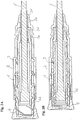
- FIGS. 1A to 1C show an injection device according to the invention with a housing 2 and with a metering device, which has an internal thread 2a with a first pitch of z. B. 49 ° has.
- Coaxial in the Housing rotatably mounted is a rotary sleeve 1 with an external thread 1a with the same pitch as the internal thread 2a of the housing 2, which in the internal thread 2a intervenes.
- the rotary sleeve 1 has an internal thread 1b with a slope of z. B. 34 °, which is smaller than the pitch of the external thread 1a and the internal thread 2a of the housing.
- the difference of the thread pitches is z. In the range of 10 to 15 degrees.
- a feed member 3 is mounted, which has an external thread 3a, which engages in the internal thread 1b of the rotary sleeve 1.
- two lugs or cams 3f attached to elastic arms 3e are mounted, which can engage in the toothing provided on the outside of a toothed rack 5 which is axially displaceable within the advancing link 3.
- the lugs or cams 3f of the feed member 3 are as well as the lugs or cams 2f, which are connected to the housing 2 and in FIG.
- the rotary sleeve 1 is connected to a control knob 4 and rotatably mounted in this by a provided on the inside of the control knob 4 circumferential groove 4a, in which a provided on the outside of the rotary sleeve 1 circumferential ring 1c engages. If the control knob 4 is pulled out of the housing 2 by a user, then the rotary sleeve 1 is entrained by the latter, which is rotated relative to the housing 2 when pulled out due to the external thread 1a engaged in the internal thread 2a of the housing 2.
- This rotation of the rotary sleeve 1 is converted into an axial movement of the feed member 3 due to the external thread 3a engaged with the internal thread 1b of the rotary sleeve 1 of the relative to the housing 2 rotatably mounted feed member 3. Due to the larger pitch of the external thread 1a of the rotary sleeve in comparison to the internal thread 1b of the rotary sleeve is a Ausschubweg D, as in FIG. 1B shown reduced in a smaller Ausschubweg d of the feed member 3, so that small doses can be precisely adjusted.
- FIG. 1B is the injection device with the metering device after pulling out of the control knob 4 by a distance D of z. B. 5 mm, resulting in the reduced axial movement by the distance d of z. B. 0.8119 mm of the feed member 3 leads until the stop 3d of the feed member 3 abuts the distal side of the stop element 2b, whereby the Ausschubterrorism the control knob 4 is limited.
- the rotary sleeve 1 was z. B. rotated by -90 °.
- the toothed rack 5 is held by the lugs 3f engaging in the teeth and displaced together with the feed member 3 in the distal direction, wherein the rack is displaced relative to the connected to the housing 2 lugs 2 f by the path d, which engage after completion of the feed operation in teeth of the rack 5, which axially in the proximal direction in comparison to Figure 1A shown starting position are offset.
- This feed movement of the rack 5 is on the in FIG. 3 shown piston 6 is inserted, which is inserted into the inserted into the injection device ampule 7 and thus a contained in the ampoule 7 substance such. As insulin, displaced, so that the feed movement d of the piston 6 corresponding amount of substance is discharged from the ampoule 7.
- FIGS. 2A and 2B show in cross section a further embodiment of the injection device according to the invention with the metering device, wherein the control knob 4 axially into the housing 2 protruding webs 4b or a cylindrical circumferential in a corresponding recess of the housing 2 insertable element 4b has.
- the control knob 4 When pulling out the control knob 4 is thus not the outside of the rotating sleeve 1 visible, such. In FIG. 1B but the outside of the element 4b, as shown in FIG FIG. 2A shown.
- markings may be appropriate to inform a user information regarding a set due to the ejection from the housing 2 dose z. As indicated by colored markers or rings.
Landscapes
- Health & Medical Sciences (AREA)
- Vascular Medicine (AREA)
- Engineering & Computer Science (AREA)
- Anesthesiology (AREA)
- Biomedical Technology (AREA)
- Heart & Thoracic Surgery (AREA)
- Hematology (AREA)
- Life Sciences & Earth Sciences (AREA)
- Animal Behavior & Ethology (AREA)
- General Health & Medical Sciences (AREA)
- Public Health (AREA)
- Veterinary Medicine (AREA)
- Infusion, Injection, And Reservoir Apparatuses (AREA)
Description
- Die vorliegende Erfindung bezieht sich auf eine Injektionsvorrichtung mit einer Dosiervorrichtung zur Einstellung einer aus der Injektionsvorrichtung abzugebenden Dosis, insbesondere auf eine Injektionsvorrichtung mit einer Dosiervorrichtung zur Einstellung einer oder mehrerer fest vorgegebener Dosiseinheiten oder zur Vorbereitung der Injektionsvorrichtung zur Abgabe einer oder mehrerer fest voreingestellter Dosismengen z. B. aus einer in die Injektionsvorrichtung eingelegten Ampulle.
- Eine Vorrichtung, wie die Erfindung sie betrifft, ist beispielsweise aus der
WO 97/36626 - Die
WO2004078239 beschreibt einen Antriebsmechanismus für ein Injektionsgerät wo eine Einstellbewegung des Einstellelementes auf eine Antriebshülse übertragen wird, wobei eine mit der Antriebshülse im Eingriff stehende Kolbenstange nicht bewegt wird. Bei der Dosisausschüttung wird eine axiale Bewegung der Antriebshülse in eine Schraubbewegung der Kolbenstange umgesetzt. DieWO2004078239 offenbart die Merkmale des einleitenden Teils des Anspruchs 1. - Des Weiteren beschreiben die
EP0937471 ,US5271527 undWO2004030730 Injektionsvorrichtungen für die Verabreichung eines Medikaments sowie diese dem Fachmann aus dem Stand der Technik bekannt sind. - Es ist eine Aufgabe der vorliegenden Erfindung eine Injektionsvorrichtung mit einer Dosiereinrichtung vorzuschlagen, welche das Einstellen einer Dosis und insbesondere das exakte Einstellen und Ausschütten einer kleinen Dosismenge vereinfacht.
- Diese Aufgabe wird durch eine Dosiervorrichtung gemäß Anspruch 1 gelöst. Vorteilhafte Ausführungsformen ergeben sich aus den abhängigen Ansprüchen.
- Eine erfindungsgemäße Injektionsvorrichtung mit einer Dosiervorrichtung weist ein Einstellelement auf, welches mit einer bevorzugt etwa zylinderförmigen Drehhülse drehbar verbunden ist. Die Drehhülse weist ein Innengewinde und ein Außengewinde mit bevorzugt gleichem Drehsinn auf, welche bevorzugt koaxial zueinander angeordnet sind, so dass die Drehhülse in mindestens einem Bereich ein Innengewinde und ein Außengewinde aufweist, welche sich bevorzugt überlappen und z. B. auch etwa über die gesamte Länge der Drehhülse an der Innenseite und der Außenseite des zylinderförmigen Drehhülsenkörpers angeordnet sein können. Die Gewinde sind bevorzugt als Bewegungsgewinde so ausgebildet, dass die Gewinde nicht selbsthemmend sind und können Gewindegänge oder in Gewindegänge eingreifende Elemente oder Nocken oder auch umlaufende Spiralen sein, welche in die Gewinde jeweils gegenüberliegender Gegengewinde eingreifen oder mit diesen zusammenwirken können. Innerhalb und außerhalb der Drehhülse sind Elemente der Injektionsvorrichtung vorgesehen, welche bevorzugt relativ zueinander verdrehgesichert sind oder welche z.B. bezüglich einem Gehäuse der Injektionsvorrichtung verdrehgesichert sind.
- Dabei weist erfindungsgemäß das Innengewinde der Drehhülse eine andere Steigung auf als das Außengewinde der Drehhülse.
- Ist z. B. innerhalb der Drehhülse ein Vorschubglied der Injektionsvorrichtung gelagert, welches sich im Gewindeeingriff mit der Drehhülse befindet, so kann eine definierte Bewegung des Vorschubgliedes um eine vorgegebene Distanz in proximale und distale Richtung der Injektionsvorrichtung durch ein Drehen der Drehhülse bewirkt werden, welche in einem Gewindeeingriff mit einem z. B. an der Außenseite der Drehhülse anliegenden Gehäuseteil der Injektionsvorrichtung ist. Hat das Innengewinde der Drehhülse eine kleinere Steigung als das Außengewinde der Drehhülse, so wird, wenn die Drehhülse z. B. um die axiale Länge D aus dem Gehäuse der Injektionsvorrichtung herausgedreht wird, mit welchem die Drehhülse im Gewindeeingriff steht, das Vorschubglied um eine kleinere Distanz d in die gleiche Richtung bewegt, wodurch eine Untersetzung einer Einstellbewegung durch eine kompakte Bauart realisiert werden kann. Somit kann eine Übersetzung eines kleinen funktionalen Weges d in einen größeren Weg D zum einfachen Einstellen z. B. einer Fixdosis realisiert werden.
- Ist mit dem Vorschubglied ein Mitnehmer, wie z. B. ein Rastelement verbunden, welches z. B. an einem flexiblen Element oder Arm des Vorschubgliedes vorgesehen ist, so kann ein an dem flexiblen Element vorgesehener z. B. radial nach innen vorstehender Nocken oder Nase über die Zahnung einer als Kolbenstange dienenden Zahnstange oder das Gewinde einer Gewindestange geführt werden, wobei je nach der Größe der axialen Bewegung des Vorschubgliedes relativ zur Zahnstange ein oder mehrere Zähne der Zahnstange durch den elastisch gelagerten Nocken oder Nase überfahren werden, wodurch ein oder mehrere "Klick"-Geräusche erzeugt werden und die aus der Injektionsvorrichtung abzugebende Dosis festgelegt wird. Die so eingestellte Dosis wird durch eine durch ein Zurückschieben oder -drehen der Drehhülse bewirkte Bewegung des Vorschubgliedes oder der Vorschubhülse in distale Richtung, welche durch einen Eingriff der Nocken oder Nasen auf die Zahnstange übertragen wird und an einen unmittelbar oder mittelbar an der Zahnstange anliegenden Stopfen weitergegeben wird, welcher in eine Ampulle zur Verdrängung einer darin enthaltenen Substanz eingeschoben wird, ausgeschüttet.
- Bezüglich der prinzipiellen Funktionsweise einer Dosiervorrichtung, welche eine Vorschubhülse oder ein Vorschubglied aufweist, wird auf die deutsche Patentanmeldung mit der Anmeldenummer
10 2004 041 151.4 der Anmelderin verwiesen. - Bei den auf der Innen- und Außenseite der Drehhülse vorgesehenen Gewinde mit unterschiedlicher Steigung ist bevorzugt die Steigung desjenigen Gewindes, welches mit dem Vorschubglied im Eingriff steht, kleiner als die Steigung des gegenüberliegenden Gewindes, welches mit dem Gehäuse der Injektionsvorrichtung im Eingriff steht, bezüglich dessen das Vorschubglied bevorzugt drehsicher gelagert ist, so dass eine bei einem Einstellvorgang durch einen Gewindeeingriff der Drehhülse mit dem Gehäuse erzwungene Drehung der Drehhülse relativ zu dem Gehäuse nicht in eine Drehung des ebenfalls im Gewindeeingriff mit der Drehhülse stehenden Vorschubgliedes, sondern in eine Axialbewegung des Vorschubgliedes relativ zum Gehäuse umgesetzt wird. Dabei kann das Vorschubglied sowohl innerhalb, als auch außerhalb, der Drehhülse mit einem Außen- oder Innengewinde vorgesehen sein. Ebenso ist es möglich, dass die Steigung des Gewindes, mit welchem Drehhülse und Vorschubglied in Eingriff stehen, größer ist als die Steigung des auf der anderen Seite der Drehhülse vorgesehenen Gewindes, wobei in diesem Fall eine kleine Einstellbewegung in eine im Verhältnis dazu größere Axialbewegung des Vorschubgliedes umgesetzt wird.
- An der Drehhülse ist ein Einstellelement, wie z. B. ein Bedienknopf vorgesehen.
- Die Drehhülse ist drehbar mit dem Einstellelement verbunden, so dass der Bedienknopf z. B. ohne Drehbewegung aus dem Gehäuse der Injektionsvorrichtung herausgezogen werden kann und die drehbar im Bedienknopf gelagerte Drehhülse aus dem Gehäuse der Injektionsvorrichtung herausgedreht wird.
- Vorzugsweise sind die an der Drehhülse vorgesehenen Gewinde nicht selbsthemmend, wobei z. B. der Steigungswinkel des Gewindes so gewählt werden kann, dass der Tangens dieses Steigungswinkels größer als der Reibungskoeffizient der aneinander liegenden und im Gewindeeingriff stehenden Materialien ist. Es können auch Schmiermittel, wie z. B. Teflon, verwendet werden, um nicht selbsthemmende Gewindeeingriffe zu realisieren. Ebenso kann z. B. eine Torsionsfeder vorgesehen sein, welche beim Herausziehen oder- drehen der Drehhülse gespannt oder aufgezogen wird und so z. B. mit der Drehhülse verbunden ist, dass beim Einschieben oder -drehen der Drehhülse die Federkraft in Drehrichtung wirkt, so dass auch selbsthemmende Gewinde verwendet werden können, wobei die Hemmung der Gewinde durch die Feder aufgehoben wird.
- Bevorzugt sind die Außen- und Innengewinde der Drehhülse koaxial zueinander angeordnet, d. h. die Gewinde überlappen sich in axialer Richtung, wodurch eine kompakte und die Bauhöhe der Injektionsvorrichtung verringernde Bauweise einer Übersetzung bzw. Untersetzung realisiert werden kann.
- Vorzugsweise sind Radial- und/oder Axialanschläge vorgesehen, welche z. B. die Bewegung des Vorschubgliedes und/oder der Drehhülse in radialer und/oder axialer Richtung z. B. relativ zum Gehäuse der Injektionsvorrichtung begrenzen können. Beispielsweise können auf dem Vorschubglied zwei in axialer Richtung voneinander beabstandete Anschläge vorgesehen sein, welche mit einem Anschlagselement des Gehäuses so zusammenwirken, dass das Vorschubglied in axialer Richtung der Injektionsvorrichtung relativ zum Gehäuse nur um eine vorgegebene Distanz d bewegt werden kann, wodurch z. B. eine der Distanz d entsprechende Dosismenge voreingestellt werden kann, die mit der Injektionsvorrichtung abgegeben werden kann. Ebenso können beispielsweise Radialanschläge an der Drehhülse und/oder an den mit der Drehhülse zusammenwirkenden Elementen, also dem Vorschubglied und einem weiteren Element wie z. B. dem Gehäuse vorgesehen sein, welche eine Drehbewegung der Drehhülse begrenzen und z. B. nur eine maximale Drehung von 180° oder beispielsweise zwei volle Umdrehungen ermöglichen. Insbesondere kann mit solchen Anschlägen eine feste Dosis vorgegeben werden, so dass ein Benutzer das Einstellelement z. B. bis zu einem Anschlag eines Elements herauszieht, wobei die voreingestellte Dosis beim Einschieben des Einstellelements abgegeben wird.
- Bevorzugt ist an der Drehhülse und/oder an dem mit der Drehhülse verbundenen Einstellelement, wie z. B. einem Bedienknopf, eine Markierung vorgesehen, welche bei einem in die Injektionsvorrichtung eingeschobenen Zustand nicht oder durch z. B. eine Öffnung oder transparentes Material ablesbar ist und welche von einem Benutzer abgelesen oder gesehen werden kann, wenn die Drehhülse und/oder ein mit der Drehhülse verbundenes Bedienelement aus der Injektionsvorrichtung oder dem Gehäuse der Injektionsvorrichtung herausgezogen wurden, so dass es einem Benutzer ermöglicht wird, die aufgrund des Ausschubweges festgelegte eingestellte Dosis abzulesen, die beim Zurückschieben der Drehhülse oder des Bedienknopfes durch die auf die Zahnstange und den Stopfen übertragene Einschubbewegung aus der Injektionsvorrichtung abgegeben wird.
- Weiterhin bezieht sich die Erfindung auf eine wie oben beschriebene Injektionsvorrichtung, in welcher eine abzugebende Substanz enthalten ist oder in einer Ampulle eingelegt werden kann und wobei die Dosiervorrichtung mit einem Verdrängungskörper oder Stopfen der Injektionsvorrichtung so gekoppelt werden kann, dass durch die Drehhülse eine abzugebende Dosis eingestellt und ausgeschüttet werden kann.
- Die Erfindung wird nachfolgend anhand bevorzugter Ausführungsbeispiele beschrieben. Es zeigen:
-
Figuren 1A bis 1C eine erfindungsgemäße Injektionsvorrichtung mit einer Dosiervorrichtung in Grundstellung, beim Einstellen und nach dem Ausschütten einer Dosis; -
Figuren 2A und 2B die erfindungsgemäße Injektionsvorrichtung mit einer Dosiervorrichtung im Querschnitt; und -
Figur 3 die erfindungsgemäße Injektionsvorrichtung mit einer Dosiervorrichtung. - Die
Figuren 1A bis 1C zeigen eine erfindungsgemäße Injektionsvorrichtung mit einem Gehäuse 2 und mit einer Dosiervorrichtung, welche ein Innengewinde 2a mit einer ersten Steigung von z. B. 49° hat. Koaxial in dem Gehäuse drehbar gelagert ist eine Drehhülse 1 mit einem Außengewinde 1a mit der gleichen Steigung wie das Innengewinde 2a des Gehäuses 2, welches in das Innengewinde 2a eingreift. Die Drehhülse 1 hat ein Innengewinde 1b mit einer Steigung von z. B. 34°, welche kleiner ist als die Steigung des Außengewindes 1a bzw. des Innengewindes 2a des Gehäuses. Der Unterschied der Gewindesteigungen liegt z. B. im Bereich von 10 bis 15 Grad. Innerhalb der Drehhülse 1 ist verdrehgesichert zum Gehäuse 2 ein Vorschubglied 3 gelagert, welches ein Außengewinde 3a hat, das in das Innengewinde 1b der Drehhülse 1 eingreift. An der inFigur 1A links gezeigten distalen oder Vorderseite des Vorschubgliedes 3 sind einander gegenüberliegend zwei an elastischen Armen 3e befestigte Nasen oder Nocken 3f angebracht, welche in die auf der Außenseite einer Zahnstange 5, welche axial verschiebbar innerhalb des Vorschubgliedes 3 angeordnet ist, vorhandene Zahnung eingreifen können. Die Nasen oder Nocken 3f des Vorschubgliedes 3 sind ebenso wie die Nasen oder Nocken 2f, welche mit dem Gehäuse 2 verbunden und inFigur 3 gezeigt sind, in proximaler Richtung relativ zur Zahnstange bewegbar, wobei die Nasen 2f, 3f entgegen die elastische oder Federkraft der elastischen Arme 2e bzw. 3e nach außen gedrückt werden, um über einen oder mehrere Zähne der Zahnstange 5 hinweg bewegt zu werden. Jedoch werden die Nasen 2f und 3f durch die in Richtung auf die Zahnstange 5 wirkende Vorspannung der elastischen Arme 2e und 3e auf die Zahnstange 5 und so in einen Eingriff mit der Zahnung gedrückt, dass eine Bewegung der Nasen 2f und 3f in distale Richtung der Zahnstange 5 nicht möglich ist bzw. durch den Eingriff der Nasen 2f und 3f in die Zahnung der Zahnstange 5 behindert wird. - Am proximalen Ende ist die Drehhülse 1 mit einem Bedienknopf 4 verbunden und drehbar in diesem durch eine auf der Innenseite des Bedienknopfes 4 vorgesehene umlaufende Nut 4a gelagert, in welche ein auf der Außenseite der Drehhülse 1 vorgesehener umlaufender Ring 1c eingreift. Wird der Bedienknopf 4 von einem Benutzer aus dem Gehäuse 2 herausgezogen, so wird von diesem die Drehhülse 1 mitgenommen, welche aufgrund des in das Innengewinde 2a des Gehäuses 2 eingreifenden Außengewindes 1a relativ zum Gehäuse 2 beim Herausziehen gedreht wird. Diese Drehung der Drehhülse 1 wird aufgrund des sich mit dem Innengewinde 1b der Drehhülse 1 in Eingriff befindlichen Außengewindes 3a des relativ zum Gehäuse 2 verdrehsicher gelagerten Vorschubgliedes 3 in eine Axialbewegung des Vorschubgliedes 3 umgesetzt. Aufgrund der größeren Steigung des Außengewindes 1a der Drehhülse im Vergleich zum Innengewinde 1b der Drehhülse wird ein Ausschubweg D, wie in
Figur 1B gezeigt, in einen kleineren Ausschubweg d des Vorschubgliedes 3 untersetzt, so dass kleine Dosismengen präzise eingestellt werden können. - Auf der Außenseite des Vorschubgliedes 3 sind zwei radial nach außen vorstehende axial beabstandete Anschläge 3c und 3d vorgesehen, zwischen welchen das Anschlagselement 2b, welches mit dem Gehäuse 2 verbunden ist, eingreift. In der in
Figur 1A gezeigten Ausgangsstellung liegt der distale axiale Anschlag 3c des Vorschubgliedes an der distalen Seite des Anschlagselementes 2b an. Der proximale Anschlag 3d des Vorschubgliedes hat einen Abstand d von der distalen Seite des Anschlagselements 2b. - In
Figur 1B ist die Injektionsvorrichtung mit der Dosiervorrichtung nach dem Herausziehen des Bedienknopfes 4 um einen Weg D von z. B. 5 mm gezeigt, was zu der untersetzten Axialbewegung um die Entfernung d von z. B. 0,8119 mm des Vorschubgliedes 3 führt, bis der Anschlag 3d des Vorschubgliedes 3 an der distalen Seite des Anschlagselementes 2b anliegt, wodurch die Ausschubbewegung des Bedienknopfes 4 begrenzt wird. Die Drehhülse 1 wurde dabei z. B. um -90° gedreht. - Beim Herausziehen des Bedienknopfes 4 und der Verschiebung des Vorschubgliedes 3 in proximale Richtung werden die mit dem Vorschubglied 3 verbundenen Nasen oder Nocken 3f in proximale Richtung entlang der durch die mit dem Gehäuse 2 verbundenen Nasen 2f gehaltenen Zahnstange 5 verschoben, so dass die sich einander gegenüberliegenden Nasen 3f z. B. jeweils über einen, zwei oder auch mehr Zähne der Zahnstange 5 nach hinten verschoben werden.
- Drückt ein Benutzer auf den Bedienknopf 4 und schiebt diesen wieder zurück in das Gehäuse 2 ein, wie in
Figur 1C gezeigt, so wird die Einschubbewegung des Bedienknopfes auf die Drehhülse 1 übertragen, welche sich aufgrund des Gewindeeingriffes mit dem Gehäuse 2 relativ zu diesem um z. B. +90° dreht und durch den Gewindeeingriff mit dem Vorschubglied 3 dieses axial nach vorne schiebt, bis wieder der proximale Anschlag 3c an dem Anschlagselement 2b und die Vorderseite der Drehhülse 1 an einem Anschlag 3b des Vorschubgliedes 3 anliegt. Dabei wird die Zahnstange 5 durch die in die Zahnung eingreifenden Nasen 3f gehalten und zusammen mit dem Vorschubglied 3 in distale Richtung verschoben, wobei die Zahnstange relativ zu dem mit dem Gehäuse 2 verbundenen Nasen 2f um den Weg d verschoben wird, welche nach Beendigung des Vorschubvorganges in Zähne der Zahnstange 5 eingreifen, welche axial in proximale Richtung im Vergleich zur inFigur 1A gezeigten Ausgangsstellung versetzt sind. Diese Vorschubbewegung der Zahnstange 5 wird auf den inFigur 3 gezeigten Kolben 6 übertragen, welcher in die in der Injektionsvorrichtung eingesetzte Ampulle 7 eingeschoben wird und so eine in der Ampulle 7 enthaltene Substanz, wie z. B. Insulin, verdrängt, so dass die der Vorschubbewegung d des Kolbens 6 entsprechende Substanzmenge aus der Ampulle 7 abgegeben wird. - Die
Figuren 2A und 2B zeigen im Querschnitt eine weitere Ausführungsform der erfindungsgemäßen Injektionsvorrichtung mit der Dosiervorrichtung, wobei der Bedienknopf 4 axial in das Gehäuse 2 hineinragende Stege 4b oder auch ein zylinderförmig umlaufendes in eine entsprechende Vertiefung des Gehäuses 2 einschiebbares Element 4b aufweist. Beim Herausziehen des Bedienknopfes 4 ist somit nicht die Außenseite der Drehhülse 1 sichtbar, wie z. B. inFigur 1B gezeigt, sondern die Außenseite des Elementes 4b, wie inFigur 2A gezeigt. - Sowohl auf der Außenseite der Drehhülse 1, als auch auf der Außenseite des Elementes 4b können Markierungen angebracht sein, um einem Benutzer Informationen bezüglich einer aufgrund des Ausschubes aus dem Gehäuse 2 eingestellten Dosis z. B. durch farbige Markierungen oder Ringe anzuzeigen.
Claims (14)
- Injektionsvorrichtung mit einer Dosiervorrichtung mit einem Einstellelement (4), einer bevorzugt etwa zylinderförmigen Drehhülse (1), welche mit dem Einstellelement (4) drehbar verbunden ist und ein Außengewinde (1a) und ein Innengewinde (1b) aufweist, welches eine andere Steigung als das Außengewinde (1a) hat, wobei eines der Gewinde (1a, 1b) der Drehhülse (1) mit einem Gewinde (2a) eines Gehäuses der Injektionsvorrichtung im Eingriff steht und das andere der Gewinde (1a, 1b) der Drehhülse (1) mit einem Gewinde (3a) eines Vorschubglieds (3) im Eingriff steht,
dadurch gekennzeichnet dass eine Einstellbewegung des Einstellelementes (4) von der Drehhülse (1) durch die beiden Gewindeeingriffe (1a, 2a; 1b, 3a) in eine Dosierbewegung des Vorschubgliedes (3) übersetzt oder untersetzt werden kann. - Injektionsvorrichtung nach Anspruch 1, wobei die Steigung desjenigen Gewindes (1b) der Drehhülse (1), welches mit dem Vorschubglied (3) im Eingriff steht, kleiner ist als die Steigung des anderen Gewindes (1a) der Drehhülse (1).
- Injektionsvorrichtung nach Anspruch 1, wobei die Steigung desjenigen Gewindes (1b) der Drehhülse (1), welches mit dem Vorschubglied (3) im Eingriff steht, größer ist als die Steigung des anderen Gewindes (1a) der Drehhülse (1).
- Injektionsvorrichtung nach einem der vorhergehenden Ansprüche, wobei der Unterschied der Gewindesteigungen im Bereich von 5 bis 30 oder 10 bis 15 Grad liegt.
- Injektionsvorrichtung nach einem der vorhergehenden Ansprüche, wobei das Vorschubglied (3) relativ zum Gehäuse (2) verdrehgesichert gelagert ist.
- Injektionsvorrichtung nach einem der vorhergehenden Ansprüche, wobei an dem Gehäuse (2) ein Innengewinde (2a) vorgesehen ist, in welches das Außengewinde (1a) der Drehhülse (1) eingreift und das Vorschubglied (3) ein Außengewinde (3a) aufweist, das in das Innengewinde (1b) der Drehhülse eingreift.
- Injektionsvorrichtung nach einem der vorhergehenden Ansprüche, wobei die Gewindesteigungen der Drehhülse (I)5 des Gehäuses (2) und des Vorschubgliedes (3) so gewählt werden, dass die Gewinde nicht selbsthemmend sind.
- Injektionsvorrichtung nach einem der vorhergehenden Ansprüche, wobei ein Federelement, insbesondere eine Torsionsfeder vorgesehen ist, welche in oder gegen die Drehrichtung der Drehhülse wirkt.
- Injektionsvorrichtung nach einem der vorhergehenden Ansprüche, wobei das Außengewinde (1a) der Drehhülse (1) koaxial und in radialer Richtung zumindest zum Teil überlappend relativ zu dem Innengewinde (1b) der Drehhülse (1) angeordnet ist.
- Injektionsvorrichtung nach einem der vorhergehenden Ansprüche, wobei an dem Vorschubglied (3) mindestens eine Rastnase oder Rastnocke (3f) bevorzugt an einem elastischen Element oder Arm (3e) angebracht ist.
- Injektionsvorrichtung nach einem der vorhergehenden Ansprüche mit einer Zahnstange (5), welche axial verschiebbar innerhalb der Dosiervorrichtung und bevorzugt innerhalb des Vorschubgliedes (3) gelagert ist und mindestens eine oder zwei Zahnreihen an der Außenseite aufweist, in welche mindestens eine elastisch gelagerte Rastnase (3f) des Vorschubgliedes (3) und/oder mindestens eine elastisch gelagerte Rastnase (2f), welche mit dem Gehäuse (2) verbunden ist, eingreifen kann.
- Injektionsvorrichtung nach einem der vorhergehenden Ansprüche mit mindestens einem radialen und/oder axialen Anschlag (3c, 3d) am Vorschubglied (3) und/oder an der Drehhülse (1) und/oder am Gehäuse (2), um eine Radial- und/oder Axialbewegung des Vorschubgliedes (3) und/oder der Drehhülse (1) relativ zum Gehäuse (2) zu begrenzen.
- Injektionsvorrichtung nach einem der vorhergehenden Ansprüche, wobei auf einer Außenseite des Einstellelementes (4) und/oder einer Außenseite der Drehhülse (1) Markierungen zur Anzeige einer eingestellten Dosis aufgebracht sind.
- Injektionsvorrichtung nach einem der vorhergehenden Ansprüche, in welcher eine abzugebende Substanz enthalten ist oder in einer Ampulle (7) eingelegt werden kann.
Applications Claiming Priority (2)
| Application Number | Priority Date | Filing Date | Title |
|---|---|---|---|
| DE102005001159A DE102005001159A1 (de) | 2005-01-10 | 2005-01-10 | Dosiervorrichtung für eine Injektionsvorrichtung mit Übersetzung |
| PCT/CH2005/000740 WO2006072188A1 (de) | 2005-01-10 | 2005-12-12 | Dosiervorrichtung für eine injektionsvorrichtung mit übersetzung |
Publications (2)
| Publication Number | Publication Date |
|---|---|
| EP1838368A1 EP1838368A1 (de) | 2007-10-03 |
| EP1838368B1 true EP1838368B1 (de) | 2019-01-16 |
Family
ID=35825379
Family Applications (1)
| Application Number | Title | Priority Date | Filing Date |
|---|---|---|---|
| EP05812740.8A Expired - Lifetime EP1838368B1 (de) | 2005-01-10 | 2005-12-12 | Injektionsvorrichtung mit einer dosiervorrichtung |
Country Status (7)
| Country | Link |
|---|---|
| US (1) | US20070299406A1 (de) |
| EP (1) | EP1838368B1 (de) |
| JP (1) | JP4593632B2 (de) |
| CN (1) | CN101094702B (de) |
| AU (1) | AU2005324262B2 (de) |
| DE (1) | DE102005001159A1 (de) |
| WO (1) | WO2006072188A1 (de) |
Families Citing this family (9)
| Publication number | Priority date | Publication date | Assignee | Title |
|---|---|---|---|---|
| DE102005023824A1 (de) | 2005-05-24 | 2006-12-07 | Tecpharma Licensing Ag | Dosiervorrichtung für eine Injektionsvorrichtung |
| DE102005023823B4 (de) | 2005-05-24 | 2022-11-17 | Tecpharma Licensing Ag | Dosiervorrichtung für eine Injektionsvorrichtung und Injektionsvorrichtung mit einer solchen Dosiervorrichtung |
| DE102007019124A1 (de) | 2007-04-23 | 2008-11-06 | Tecpharma Licensing Ag | Rückdrehbare Dosiervorrichtung für eine Injektionsvorrichtung |
| JP2010540046A (ja) | 2007-09-25 | 2010-12-24 | モラー,クラウス,シュミット | 伝動構造を有する投与量送出装置 |
| EP2234661B1 (de) | 2007-12-20 | 2013-04-17 | Novo Nordisk A/S | Einspritzvorrichtung zur verabreichung einer festgelegten dosis eines flüssigen arzneimittels |
| AU2010254627B2 (en) * | 2009-06-05 | 2012-08-02 | Shl Group Ab | Medicament delivery device |
| US8939438B2 (en) | 2010-01-08 | 2015-01-27 | Lee Spring Company Llc | Plastic spring and method and apparatus for making the same |
| DK2838591T3 (da) | 2012-04-19 | 2023-02-06 | Sanofi Aventis Deutschland | Indretning til en lægemiddeladministrationsanordning og lægemiddeladministrationsanordning |
| US20160038676A1 (en) * | 2013-04-10 | 2016-02-11 | Sanofi | Injection Device |
Family Cites Families (13)
| Publication number | Priority date | Publication date | Assignee | Title |
|---|---|---|---|---|
| US5271527A (en) * | 1992-04-02 | 1993-12-21 | Habley Medical Technology Corporation | Reusable pharmaceutical dispenser with full stroke indicator |
| PT828527E (pt) * | 1996-04-02 | 2002-12-31 | Disetronic Licensing Ag | Dispositivo para injeccao |
| CZ297361B6 (cs) * | 1998-01-30 | 2006-11-15 | Novo Nordisk A/S | Injekcní stríkacka |
| US6221053B1 (en) * | 1998-02-20 | 2001-04-24 | Becton, Dickinson And Company | Multi-featured medication delivery pen |
| US6663602B2 (en) * | 2000-06-16 | 2003-12-16 | Novo Nordisk A/S | Injection device |
| DE10047637A1 (de) * | 2000-09-26 | 2002-04-25 | Disetronic Licensing Ag | Vorrichtung zur Verabreichung eines injizierbaren Produkts |
| US6899699B2 (en) * | 2001-01-05 | 2005-05-31 | Novo Nordisk A/S | Automatic injection device with reset feature |
| EP2275158B1 (de) * | 2001-05-16 | 2013-01-23 | Eli Lilly and Company | Spritzvorrichtung |
| DE10232410B4 (de) * | 2002-07-17 | 2006-12-21 | Tecpharma Licensing Ag | Verabreichungsgerät mit Dosisanzeige |
| EP1545663B1 (de) * | 2002-10-01 | 2006-08-30 | Becton Dickinson and Company | Stiftförmige medikamentenspritze |
| GB0304822D0 (en) * | 2003-03-03 | 2003-04-09 | Dca Internat Ltd | Improvements in and relating to a pen-type injector |
| TR201903984T4 (tr) * | 2003-08-12 | 2019-04-22 | Lilly Co Eli | Mekanik avantaja yönelik üçlü vida dişine sahip ilaç dağıtım aparatı. |
| DE20317377U1 (de) * | 2003-11-03 | 2005-03-17 | B D Medico S A R L | Injektionsgerät |
-
2005
- 2005-01-10 DE DE102005001159A patent/DE102005001159A1/de not_active Withdrawn
- 2005-12-12 CN CN2005800459064A patent/CN101094702B/zh not_active Expired - Fee Related
- 2005-12-12 EP EP05812740.8A patent/EP1838368B1/de not_active Expired - Lifetime
- 2005-12-12 JP JP2007549775A patent/JP4593632B2/ja not_active Expired - Fee Related
- 2005-12-12 AU AU2005324262A patent/AU2005324262B2/en not_active Ceased
- 2005-12-12 WO PCT/CH2005/000740 patent/WO2006072188A1/de not_active Ceased
-
2007
- 2007-07-09 US US11/774,844 patent/US20070299406A1/en not_active Abandoned
Non-Patent Citations (1)
| Title |
|---|
| None * |
Also Published As
| Publication number | Publication date |
|---|---|
| CN101094702A (zh) | 2007-12-26 |
| EP1838368A1 (de) | 2007-10-03 |
| WO2006072188A1 (de) | 2006-07-13 |
| US20070299406A1 (en) | 2007-12-27 |
| CN101094702B (zh) | 2011-12-14 |
| DE102005001159A1 (de) | 2006-07-20 |
| AU2005324262B2 (en) | 2009-09-10 |
| JP4593632B2 (ja) | 2010-12-08 |
| AU2005324262A1 (en) | 2006-07-13 |
| JP2008526325A (ja) | 2008-07-24 |
Similar Documents
| Publication | Publication Date | Title |
|---|---|---|
| EP1833536B1 (de) | Vorrichtung zur dosierten verabreichung eines fluiden produkts mit kupplung | |
| EP2379138B1 (de) | Dosiervorrichtung für eine injektionsvorrichtung | |
| EP1926514B1 (de) | Injektionsvorrichtung mit zweiwege-rutschkupplung | |
| EP2065065B2 (de) | Dosiervorrichtung für eine Injektionsvorrichtung | |
| EP2829292B1 (de) | Antriebs- und Dosiervorrichtung mit einem Begrenzungselement zur Verhinderung der Einstellung einer höheren Dosis als verfügbar | |
| EP2152340B1 (de) | Rückdrehbare dosiervorrichtung für eine injektionsvorrichtung | |
| DE102005060928A1 (de) | Injektionsvorrichtung mit axial überlappendem Dosier- oder Anzeigeglied | |
| EP3795194A1 (de) | Injektionsgerät zur verabreichung oder förderung von fluidem produkt | |
| DE202009019077U1 (de) | Antriebsmechanismus für eine Medikamentenabgabevorrichtung und Medikamentenabgabevorrichtung | |
| EP4159257A1 (de) | Injektionsgerät mit verbessertem förderelement | |
| EP2445551A1 (de) | Injektionsvorrichtung mit einem dosiermechanismus zum begrenzen einer dosiseinstellung | |
| WO2009062686A1 (de) | Injektionsvorrichtung mit betätigungsaktivierter kupplung | |
| EP1890750B1 (de) | Längenausgleich für eine einstellvorrichtung einer injektionsvorrichtung | |
| EP1523356A1 (de) | Verabreichungsgerät mit rückzugsgesperrter kolbenstange | |
| EP2692376B1 (de) | Injektionsvorrichtung mit einer helix- bzw. wendelförmigen Dosisskala | |
| EP1838368A1 (de) | Dosiervorrichtung für eine injektionsvorrichtung mit übersetzung | |
| EP2692379B1 (de) | Injektionsvorrichtung mit einer Kupplung | |
| EP2219713A1 (de) | Injektionsvorrichtung mit betätigungsaktivierter kupplung | |
| WO2011057677A1 (de) | Verabreichungsvorrichtung mit überlastsicherung bei dosiseinstellung | |
| WO2009056345A1 (de) | Dosiersystem für eine injektionsvorrichtung und injektionsvorrichtung |
Legal Events
| Date | Code | Title | Description |
|---|---|---|---|
| PUAI | Public reference made under article 153(3) epc to a published international application that has entered the european phase |
Free format text: ORIGINAL CODE: 0009012 |
|
| 17P | Request for examination filed |
Effective date: 20070810 |
|
| AK | Designated contracting states |
Kind code of ref document: A1 Designated state(s): AT BE BG CH CY CZ DE DK EE ES FI FR GB GR HU IE IS IT LI LT LU LV MC NL PL PT RO SE SI SK TR |
|
| RIN1 | Information on inventor provided before grant (corrected) |
Inventor name: ZURFLUEH, PHILIPPE Inventor name: BURREN, STEFAN Inventor name: SCHRUL, CHRISTIAN Inventor name: SCHOCH, ROLAND Inventor name: MOSER, ULRICH |
|
| DAX | Request for extension of the european patent (deleted) | ||
| 17Q | First examination report despatched |
Effective date: 20160126 |
|
| STAA | Information on the status of an ep patent application or granted ep patent |
Free format text: STATUS: EXAMINATION IS IN PROGRESS |
|
| GRAP | Despatch of communication of intention to grant a patent |
Free format text: ORIGINAL CODE: EPIDOSNIGR1 |
|
| STAA | Information on the status of an ep patent application or granted ep patent |
Free format text: STATUS: GRANT OF PATENT IS INTENDED |
|
| INTG | Intention to grant announced |
Effective date: 20181004 |
|
| GRAS | Grant fee paid |
Free format text: ORIGINAL CODE: EPIDOSNIGR3 |
|
| GRAA | (expected) grant |
Free format text: ORIGINAL CODE: 0009210 |
|
| STAA | Information on the status of an ep patent application or granted ep patent |
Free format text: STATUS: THE PATENT HAS BEEN GRANTED |
|
| AK | Designated contracting states |
Kind code of ref document: B1 Designated state(s): AT BE BG CH CY CZ DE DK EE ES FI FR GB GR HU IE IS IT LI LT LU LV MC NL PL PT RO SE SI SK TR |
|
| REG | Reference to a national code |
Ref country code: GB Ref legal event code: FG4D Free format text: NOT ENGLISH |
|
| REG | Reference to a national code |
Ref country code: CH Ref legal event code: EP |
|
| REG | Reference to a national code |
Ref country code: IE Ref legal event code: FG4D Free format text: LANGUAGE OF EP DOCUMENT: GERMAN |
|
| REG | Reference to a national code |
Ref country code: DE Ref legal event code: R096 Ref document number: 502005015981 Country of ref document: DE |
|
| REG | Reference to a national code |
Ref country code: AT Ref legal event code: REF Ref document number: 1089218 Country of ref document: AT Kind code of ref document: T Effective date: 20190215 |
|
| REG | Reference to a national code |
Ref country code: NL Ref legal event code: MP Effective date: 20190116 |
|
| REG | Reference to a national code |
Ref country code: LT Ref legal event code: MG4D |
|
| PG25 | Lapsed in a contracting state [announced via postgrant information from national office to epo] |
Ref country code: NL Free format text: LAPSE BECAUSE OF FAILURE TO SUBMIT A TRANSLATION OF THE DESCRIPTION OR TO PAY THE FEE WITHIN THE PRESCRIBED TIME-LIMIT Effective date: 20190116 |
|
| PG25 | Lapsed in a contracting state [announced via postgrant information from national office to epo] |
Ref country code: PT Free format text: LAPSE BECAUSE OF FAILURE TO SUBMIT A TRANSLATION OF THE DESCRIPTION OR TO PAY THE FEE WITHIN THE PRESCRIBED TIME-LIMIT Effective date: 20190516 Ref country code: ES Free format text: LAPSE BECAUSE OF FAILURE TO SUBMIT A TRANSLATION OF THE DESCRIPTION OR TO PAY THE FEE WITHIN THE PRESCRIBED TIME-LIMIT Effective date: 20190116 Ref country code: SE Free format text: LAPSE BECAUSE OF FAILURE TO SUBMIT A TRANSLATION OF THE DESCRIPTION OR TO PAY THE FEE WITHIN THE PRESCRIBED TIME-LIMIT Effective date: 20190116 Ref country code: PL Free format text: LAPSE BECAUSE OF FAILURE TO SUBMIT A TRANSLATION OF THE DESCRIPTION OR TO PAY THE FEE WITHIN THE PRESCRIBED TIME-LIMIT Effective date: 20190116 Ref country code: FI Free format text: LAPSE BECAUSE OF FAILURE TO SUBMIT A TRANSLATION OF THE DESCRIPTION OR TO PAY THE FEE WITHIN THE PRESCRIBED TIME-LIMIT Effective date: 20190116 Ref country code: LT Free format text: LAPSE BECAUSE OF FAILURE TO SUBMIT A TRANSLATION OF THE DESCRIPTION OR TO PAY THE FEE WITHIN THE PRESCRIBED TIME-LIMIT Effective date: 20190116 |
|
| PG25 | Lapsed in a contracting state [announced via postgrant information from national office to epo] |
Ref country code: BG Free format text: LAPSE BECAUSE OF FAILURE TO SUBMIT A TRANSLATION OF THE DESCRIPTION OR TO PAY THE FEE WITHIN THE PRESCRIBED TIME-LIMIT Effective date: 20190416 Ref country code: LV Free format text: LAPSE BECAUSE OF FAILURE TO SUBMIT A TRANSLATION OF THE DESCRIPTION OR TO PAY THE FEE WITHIN THE PRESCRIBED TIME-LIMIT Effective date: 20190116 Ref country code: IS Free format text: LAPSE BECAUSE OF FAILURE TO SUBMIT A TRANSLATION OF THE DESCRIPTION OR TO PAY THE FEE WITHIN THE PRESCRIBED TIME-LIMIT Effective date: 20190516 Ref country code: GR Free format text: LAPSE BECAUSE OF FAILURE TO SUBMIT A TRANSLATION OF THE DESCRIPTION OR TO PAY THE FEE WITHIN THE PRESCRIBED TIME-LIMIT Effective date: 20190417 |
|
| REG | Reference to a national code |
Ref country code: DE Ref legal event code: R097 Ref document number: 502005015981 Country of ref document: DE |
|
| PG25 | Lapsed in a contracting state [announced via postgrant information from national office to epo] |
Ref country code: IT Free format text: LAPSE BECAUSE OF FAILURE TO SUBMIT A TRANSLATION OF THE DESCRIPTION OR TO PAY THE FEE WITHIN THE PRESCRIBED TIME-LIMIT Effective date: 20190116 Ref country code: RO Free format text: LAPSE BECAUSE OF FAILURE TO SUBMIT A TRANSLATION OF THE DESCRIPTION OR TO PAY THE FEE WITHIN THE PRESCRIBED TIME-LIMIT Effective date: 20190116 Ref country code: SK Free format text: LAPSE BECAUSE OF FAILURE TO SUBMIT A TRANSLATION OF THE DESCRIPTION OR TO PAY THE FEE WITHIN THE PRESCRIBED TIME-LIMIT Effective date: 20190116 Ref country code: DK Free format text: LAPSE BECAUSE OF FAILURE TO SUBMIT A TRANSLATION OF THE DESCRIPTION OR TO PAY THE FEE WITHIN THE PRESCRIBED TIME-LIMIT Effective date: 20190116 Ref country code: EE Free format text: LAPSE BECAUSE OF FAILURE TO SUBMIT A TRANSLATION OF THE DESCRIPTION OR TO PAY THE FEE WITHIN THE PRESCRIBED TIME-LIMIT Effective date: 20190116 Ref country code: CZ Free format text: LAPSE BECAUSE OF FAILURE TO SUBMIT A TRANSLATION OF THE DESCRIPTION OR TO PAY THE FEE WITHIN THE PRESCRIBED TIME-LIMIT Effective date: 20190116 |
|
| PLBE | No opposition filed within time limit |
Free format text: ORIGINAL CODE: 0009261 |
|
| STAA | Information on the status of an ep patent application or granted ep patent |
Free format text: STATUS: NO OPPOSITION FILED WITHIN TIME LIMIT |
|
| 26N | No opposition filed |
Effective date: 20191017 |
|
| PG25 | Lapsed in a contracting state [announced via postgrant information from national office to epo] |
Ref country code: SI Free format text: LAPSE BECAUSE OF FAILURE TO SUBMIT A TRANSLATION OF THE DESCRIPTION OR TO PAY THE FEE WITHIN THE PRESCRIBED TIME-LIMIT Effective date: 20190116 |
|
| PG25 | Lapsed in a contracting state [announced via postgrant information from national office to epo] |
Ref country code: TR Free format text: LAPSE BECAUSE OF FAILURE TO SUBMIT A TRANSLATION OF THE DESCRIPTION OR TO PAY THE FEE WITHIN THE PRESCRIBED TIME-LIMIT Effective date: 20190116 |
|
| REG | Reference to a national code |
Ref country code: DE Ref legal event code: R119 Ref document number: 502005015981 Country of ref document: DE |
|
| REG | Reference to a national code |
Ref country code: CH Ref legal event code: PL |
|
| REG | Reference to a national code |
Ref country code: BE Ref legal event code: MM Effective date: 20191231 |
|
| PG25 | Lapsed in a contracting state [announced via postgrant information from national office to epo] |
Ref country code: MC Free format text: LAPSE BECAUSE OF FAILURE TO SUBMIT A TRANSLATION OF THE DESCRIPTION OR TO PAY THE FEE WITHIN THE PRESCRIBED TIME-LIMIT Effective date: 20190116 |
|
| GBPC | Gb: european patent ceased through non-payment of renewal fee |
Effective date: 20191212 |
|
| PG25 | Lapsed in a contracting state [announced via postgrant information from national office to epo] |
Ref country code: FR Free format text: LAPSE BECAUSE OF NON-PAYMENT OF DUE FEES Effective date: 20191231 Ref country code: LU Free format text: LAPSE BECAUSE OF NON-PAYMENT OF DUE FEES Effective date: 20191212 Ref country code: IE Free format text: LAPSE BECAUSE OF NON-PAYMENT OF DUE FEES Effective date: 20191212 Ref country code: DE Free format text: LAPSE BECAUSE OF NON-PAYMENT OF DUE FEES Effective date: 20200701 Ref country code: GB Free format text: LAPSE BECAUSE OF NON-PAYMENT OF DUE FEES Effective date: 20191212 |
|
| PG25 | Lapsed in a contracting state [announced via postgrant information from national office to epo] |
Ref country code: CH Free format text: LAPSE BECAUSE OF NON-PAYMENT OF DUE FEES Effective date: 20191231 Ref country code: LI Free format text: LAPSE BECAUSE OF NON-PAYMENT OF DUE FEES Effective date: 20191231 Ref country code: BE Free format text: LAPSE BECAUSE OF NON-PAYMENT OF DUE FEES Effective date: 20191231 |
|
| REG | Reference to a national code |
Ref country code: AT Ref legal event code: MM01 Ref document number: 1089218 Country of ref document: AT Kind code of ref document: T Effective date: 20191212 |
|
| PG25 | Lapsed in a contracting state [announced via postgrant information from national office to epo] |
Ref country code: AT Free format text: LAPSE BECAUSE OF NON-PAYMENT OF DUE FEES Effective date: 20191212 Ref country code: CY Free format text: LAPSE BECAUSE OF FAILURE TO SUBMIT A TRANSLATION OF THE DESCRIPTION OR TO PAY THE FEE WITHIN THE PRESCRIBED TIME-LIMIT Effective date: 20190116 |
|
| PG25 | Lapsed in a contracting state [announced via postgrant information from national office to epo] |
Ref country code: HU Free format text: LAPSE BECAUSE OF FAILURE TO SUBMIT A TRANSLATION OF THE DESCRIPTION OR TO PAY THE FEE WITHIN THE PRESCRIBED TIME-LIMIT; INVALID AB INITIO Effective date: 20051212 |