EP1837954A1 - Flat circuit board electrical connector - Google Patents
Flat circuit board electrical connector Download PDFInfo
- Publication number
- EP1837954A1 EP1837954A1 EP07005928A EP07005928A EP1837954A1 EP 1837954 A1 EP1837954 A1 EP 1837954A1 EP 07005928 A EP07005928 A EP 07005928A EP 07005928 A EP07005928 A EP 07005928A EP 1837954 A1 EP1837954 A1 EP 1837954A1
- Authority
- EP
- European Patent Office
- Prior art keywords
- movable member
- circuit board
- section
- flat circuit
- housing
- Prior art date
- Legal status (The legal status is an assumption and is not a legal conclusion. Google has not performed a legal analysis and makes no representation as to the accuracy of the status listed.)
- Withdrawn
Links
Images



Classifications
-
- H—ELECTRICITY
- H01—ELECTRIC ELEMENTS
- H01R—ELECTRICALLY-CONDUCTIVE CONNECTIONS; STRUCTURAL ASSOCIATIONS OF A PLURALITY OF MUTUALLY-INSULATED ELECTRICAL CONNECTING ELEMENTS; COUPLING DEVICES; CURRENT COLLECTORS
- H01R12/00—Structural associations of a plurality of mutually-insulated electrical connecting elements, specially adapted for printed circuits, e.g. printed circuit boards [PCB], flat or ribbon cables, or like generally planar structures, e.g. terminal strips, terminal blocks; Coupling devices specially adapted for printed circuits, flat or ribbon cables, or like generally planar structures; Terminals specially adapted for contact with, or insertion into, printed circuits, flat or ribbon cables, or like generally planar structures
- H01R12/70—Coupling devices
- H01R12/77—Coupling devices for flexible printed circuits, flat or ribbon cables or like structures
-
- H—ELECTRICITY
- H01—ELECTRIC ELEMENTS
- H01R—ELECTRICALLY-CONDUCTIVE CONNECTIONS; STRUCTURAL ASSOCIATIONS OF A PLURALITY OF MUTUALLY-INSULATED ELECTRICAL CONNECTING ELEMENTS; COUPLING DEVICES; CURRENT COLLECTORS
- H01R12/00—Structural associations of a plurality of mutually-insulated electrical connecting elements, specially adapted for printed circuits, e.g. printed circuit boards [PCB], flat or ribbon cables, or like generally planar structures, e.g. terminal strips, terminal blocks; Coupling devices specially adapted for printed circuits, flat or ribbon cables, or like generally planar structures; Terminals specially adapted for contact with, or insertion into, printed circuits, flat or ribbon cables, or like generally planar structures
- H01R12/70—Coupling devices
- H01R12/82—Coupling devices connected with low or zero insertion force
- H01R12/85—Coupling devices connected with low or zero insertion force contact pressure producing means, contacts activated after insertion of printed circuits or like structures
- H01R12/88—Coupling devices connected with low or zero insertion force contact pressure producing means, contacts activated after insertion of printed circuits or like structures acting manually by rotating or pivoting connector housing parts
-
- H—ELECTRICITY
- H01—ELECTRIC ELEMENTS
- H01R—ELECTRICALLY-CONDUCTIVE CONNECTIONS; STRUCTURAL ASSOCIATIONS OF A PLURALITY OF MUTUALLY-INSULATED ELECTRICAL CONNECTING ELEMENTS; COUPLING DEVICES; CURRENT COLLECTORS
- H01R12/00—Structural associations of a plurality of mutually-insulated electrical connecting elements, specially adapted for printed circuits, e.g. printed circuit boards [PCB], flat or ribbon cables, or like generally planar structures, e.g. terminal strips, terminal blocks; Coupling devices specially adapted for printed circuits, flat or ribbon cables, or like generally planar structures; Terminals specially adapted for contact with, or insertion into, printed circuits, flat or ribbon cables, or like generally planar structures
- H01R12/70—Coupling devices
- H01R12/77—Coupling devices for flexible printed circuits, flat or ribbon cables or like structures
- H01R12/79—Coupling devices for flexible printed circuits, flat or ribbon cables or like structures connecting to rigid printed circuits or like structures
Definitions
- the present invention relates to flat circuit board electrical connectors.
- the conventional flat circuit boards include flexible print circuit (FPC) boards and flat cables.
- JP 11-031561 discloses an electrical connector for connecting such a flat circuit board to another circuit board or the like.
- the electrical connector of the above reference includes a housing 52 and a plurality of flat terminals 51 supported by the housing 52.
- the terminal 51 has a substantially H-shaped form that has upper and lower arms linked at a midpoint such that the upper arm is able to swing at the midpoint.
- the upper arm has a support section 54A on the right side of the midpoint 53 and, on the left side, a contact section 54B with a contact projection 54C.
- the lower arm has a support section 55A on the right side of the midpoint 53 and, on the left side, a fixing section 55D with a projection 55C.
- a channel 56 is provided in the housing 52 to receive the terminal 51 from the right side. All the channels 56 are communicated by left and right side openings 57 and 58 of the housing 52.
- a flat circuit board is inserted into a space between the contact sections 54B and the fixing sections 55D through the left side opening 57.
- a movable member 59 is supported in the right side opening 58 for rotation.
- the movable member 59A is made of an insulative material so as to have an operational section 59A, a shaft section 59B, and a pressure section 59C.
- the operational section 59A projects from the housing 52 through the right side opening 58.
- the shaft section 59B has a semi-circular cross-section and supported by the support section 55A of the lower arm.
- a pair of stud portions 59D extends outward from the opposite sides of the movable member 59 along the center line of the shaft section 59B.
- the stud portions 59D are rotatably supported along with the shaft section 59B.
- a tapered indentation 61 and a stepped indentation 62 are provided in the inside of a side wall 60 of the housing, and a slit 64 is provided in a top wall 63 adjacent to another side wall 60, allowing the side wall 60 to flex outward.
- the movable member 59 is attached to the housing 52 from right side such that the stud portion 59 passes over the tapered indentation 61 and snaps in the stepped indentation 62, providing resistance to accidental separation.
- the stud portions snap in the stepped indentations to prevent separation of the movable member.
- the movable member becomes so wide that it becomes susceptible to warping under external forces, causing separation of the movable member, resulting in contact failure between the terminal and the flat circuit board.
- a housing 20 made of an insulative material supports a flat terminal 10.
- the flat terminal 10 is made by stamping a sheet metal so as to have a substantially H-shaped form that has parallel upper and lower arms 11 and 12 and a linking section 13 for linking them as a unit.
- the upper arm 11 has an upper support section 14 and an upper contact section 15 on right and left sides of the linking section 13.
- the lower arm 12 has a lower support section 16 and a lower contact section 17 on right and left sides of the linking section 13.
- the upper support section 14 has a downward bearing recess 14A near the right side rear end and the upper contact section 15 has a downward contact projection 15A at the left side front end.
- the lower support section 16 has an upward recess 16A from which a connection section 18 extends to the right beyond the housing 20.
- the upward recess 16A has an arc-shaped engaging edge 16B on the right side which is opposed to the bearing recess 14A of the upper support section 14.
- the width of the upward recess 16A is made slightly greater than the distance between the engaging edge 16B and the bearing recess 14A.
- connection section 18 project from the housing 20 and extends downward slightly beyond the bottom surface of the housing 20 so that the lower edge 18A of the connection section 18 comes to contact with the corresponding circuit section of a circuit board for soldering.
- An attaching recess 18B is provided on the connection section 18 to receive the bottom end of the housing 20.
- the lower contact section 17 has an upward contact projection 17A at its front end and an upward fixing projection 17B near the linking section 13.
- a plurality of the terminals 10 are press fitted in terminal slots 21 provided in the housing 20 at regular intervals in the direction perpendicular to the drawing sheet.
- the terminal slots 21 communicate with each other on the left and right sides to form left and right openings 22 and 23.
- the left opening 22 receives a flat circuit board between the upper and lower contact sections 15 and 17 while the right opening 23 receives the upper support section 14 and a portion of the movable member 20.
- a metal-fittings slot 24 is provided in the housing 20 outside the outermost terminal 10 for receiving metal fittings.
- the metal-fittings slot 24 communicates with the left and right openings 22 and 23.
- a cutout portion 24A is provided in the left bottom wall of the housing 20 for allowing metal fittings to enter the housing 20.
- a step-down portion 25 is provided on the bottom wall of the housing 20 at a position corresponding to the right opening 23. The step-down portion 25 is formed in the range including the support recess 16A of the lower support section 16.
- a regular metal fittings 30 is inserted into the metal-fitting slot 24 of the housing 20 from left or in the opposite direction that the terminal 10 is inserted.
- This flat regular metal fittings 30 is made by stamping so as to have a base section 31, a fixing arm 32, and a regulation arm 33.
- the base section 31 extends downward through the cutout portion 24A and project slightly from the housing 20, forming a fixing leg 31A.
- the fixing arm 32 has engaging projections 32A and 32B on its lower edge so that when it is press fitted, the engaging projections 32A and 32B cut into the bottom wall of the housing 20 for preventing the metal fittings 30 to come off.
- the regulation arm 33 is narrower than the fixing arm 32 and extends into the right opening 23 to the position almost the same position of the upper support section 14 of the terminal 10 as viewed in the direction perpendicular to the drawing sheet. Also, the lower edge 33A of the regulation arm 33 is level with the lower edge of the upper support section 14.
- the movable member 40 is made of an insulative material so as to serve as a lever. It has a lower section placed in the right opening 23 of the housing 20 and an upper section or operation section 41 that projects upward from the housing 20 at the open position. Slots 42 and 43 are provided in the lower section of the movable member 40 at positions corresponding to the terminal slots 21 and metal fittings slot 24, respectively, to receive the upper support arm 14 of the terminal 10 and the regulation arm 33 of the regulating metal fittings 30, respectively.
- a cam shaft 44 and a regulated island 45 are provided in the lower right corners of the slots 42 and 43, respectively. Rotation centers 44A and 45A are provided at the same positions in the cam shaft 44 and the regulated island 45, respectively.
- the cam island 44 has an elongated circular cross-section, with the right side arc having a radius substantially equal to that of the engaging edge 16B of the lower support arm 16 and the left side arc having a radius substantially equal to that of the bearing recess 14A of the upper support arm 14. In this embodiment, the radius of these four arcs are substantially equal.
- the height of the cam island 44 is less than the space between the straight lower edge of the upper support arm 14 and the upper edge of the engaging edge 16B of the lower support arm 16 so that the cam island 44 can enter in the space between the upper support arm 14 and the lower support arm 16 in the A direction.
- the width of the cam island 44 is greater than the distance between the bearing recess 14A of the upper support arm 14 and the engaging edge 16B of the lower support arm 16 so that when the movable member is turned into the closed position, the cam island 44 pushes up the upper support arm 14 for warping or flexing.
- the regulated island 45 has a substantially square cross-section with upper left and lower right rounded corners. As shown in Fig. 2(B), the height and width of the regulated island 45 are substantially equal to the distance between the lower edge 33A of the regulation arm 33 and the step-down section 25 of the housing 20 so that when the island 45 is rotated, the upper left rounded corner makes the rotation smooth and, at any rotation angle, the lower edge 33A of the regulation arm 33 is in contact with or adjacent to the regulated island 45.
- the upper right and lower left corners are not rounded so as to work as a stopper to stop the rotation beyond a predetermined angle.
- the connector is assembled and used as follows.
- the regulation arm of a regulation metal fittings may be spaced from the regulated island to such an extent that the cam island does not come off from the engaging edge.
- the cam island may take an eccentric circular cam form.
- the regulation metal fittings may be moved up or down after lateral insertion to fit into a slot of the housing.
- the regulation metal fittings may be bent in part for improving the strength.
- the regulation metal fittings may be provided in the range of arranging terminals.
Landscapes
- Coupling Device And Connection With Printed Circuit (AREA)
- Details Of Connecting Devices For Male And Female Coupling (AREA)
Abstract
A flat circuit board electrical connector includes a housing (20); a plurality of flat terminals supported having a pair of support sections (14, 16), a movable member (40) having a cam shaft (44), wherein when said movable member (40) is at said open position, said cam shaft (44) is inserted into a space between said support sections (14, 16); an engaging edge (16B) is provided at least one of said support sections (16) to engage with said can shaft (44); a regulation metal fittings (30) provided in parallel with said terminals; a regulated island (45) provided on said movable member (40); a regulation arm (33) on said regulation metal fittings (30) to regulate said regulated island (45) of said movable member (40) such that said cam shaft (44) is engaged with said engaging edge (16B).

Description
- The present invention relates to flat circuit board electrical connectors.
- The conventional flat circuit boards include flexible print circuit (FPC) boards and flat cables.
JP 11-031561 - As shown in Figs. 3 and 4, the electrical connector of the above reference includes a
housing 52 and a plurality offlat terminals 51 supported by thehousing 52. Theterminal 51 has a substantially H-shaped form that has upper and lower arms linked at a midpoint such that the upper arm is able to swing at the midpoint. The upper arm has asupport section 54A on the right side of themidpoint 53 and, on the left side, acontact section 54B with acontact projection 54C. The lower arm has asupport section 55A on the right side of themidpoint 53 and, on the left side, afixing section 55D with aprojection 55C. - A
channel 56 is provided in thehousing 52 to receive theterminal 51 from the right side. All thechannels 56 are communicated by left andright side openings housing 52. A flat circuit board is inserted into a space between thecontact sections 54B and thefixing sections 55D through the left side opening 57. Amovable member 59 is supported in the right side opening 58 for rotation. Themovable member 59A is made of an insulative material so as to have anoperational section 59A, ashaft section 59B, and apressure section 59C. Theoperational section 59A projects from thehousing 52 through the right side opening 58. Theshaft section 59B has a semi-circular cross-section and supported by thesupport section 55A of the lower arm. When themovable member 59 is turned clockwise to the closed position, thepressure section 59C pushes up thesupport section 54A of theterminal 51. - A pair of
stud portions 59D extends outward from the opposite sides of themovable member 59 along the center line of theshaft section 59B. When themovable member 59 is rotated, thestud portions 59D are rotatably supported along with theshaft section 59B. Atapered indentation 61 and astepped indentation 62 are provided in the inside of aside wall 60 of the housing, and aslit 64 is provided in atop wall 63 adjacent to anotherside wall 60, allowing theside wall 60 to flex outward. Themovable member 59 is attached to thehousing 52 from right side such that thestud portion 59 passes over thetapered indentation 61 and snaps in thestepped indentation 62, providing resistance to accidental separation. - In the connector of the above Patent reference, the stud portions snap in the stepped indentations to prevent separation of the movable member. When the number of terminals is large, however, the movable member becomes so wide that it becomes susceptible to warping under external forces, causing separation of the movable member, resulting in contact failure between the terminal and the flat circuit board.
- Accordingly, it is an object of the invention to provide a flat circuit board electrical connector capable of preventing separation of the movable member for a large number of terminals.
- The above object of the invention is achieved by the invention as recited in claim 1.
- Embodiments of the invention will now be described with respect to the accompanying drawings, in which
- Fig. 1(A) is a sectional view taken at a terminal position of a connector where no regulation metal fittings is attached and a movable member is being assembled according to an embodiment of the invention;
- Fig. 1(B) is a sectional view of the connector taken at the position where a regulation metal fittings is to be attached;
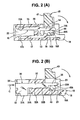
- Fig. 2(A) is a sectional view taken at the terminal position of the connector where a regulation metal fittings has been attached and the movable member is at the open position;
- Fig. 2(B) is a sectional view taken at the regulation metal fittings;
- Fig. 3 is a perspective sectional view of a conventional connector; and
- Fig. 4 is a perspective view of the connector of Fig. 4.
- In Fig. 1(A), a
housing 20 made of an insulative material supports aflat terminal 10. Theflat terminal 10 is made by stamping a sheet metal so as to have a substantially H-shaped form that has parallel upper andlower arms section 13 for linking them as a unit. Theupper arm 11 has anupper support section 14 and anupper contact section 15 on right and left sides of the linkingsection 13. Thelower arm 12 has alower support section 16 and alower contact section 17 on right and left sides of the linkingsection 13. - The
upper support section 14 has a downwardbearing recess 14A near the right side rear end and theupper contact section 15 has adownward contact projection 15A at the left side front end. Thelower support section 16 has anupward recess 16A from which aconnection section 18 extends to the right beyond thehousing 20. Theupward recess 16A has an arc-shapedengaging edge 16B on the right side which is opposed to thebearing recess 14A of theupper support section 14. The width of theupward recess 16A is made slightly greater than the distance between theengaging edge 16B and the bearing recess 14A. Theconnection section 18 project from thehousing 20 and extends downward slightly beyond the bottom surface of thehousing 20 so that thelower edge 18A of theconnection section 18 comes to contact with the corresponding circuit section of a circuit board for soldering. An attachingrecess 18B is provided on theconnection section 18 to receive the bottom end of thehousing 20. Thelower contact section 17 has anupward contact projection 17A at its front end and anupward fixing projection 17B near the linkingsection 13. - A plurality of the
terminals 10 are press fitted interminal slots 21 provided in thehousing 20 at regular intervals in the direction perpendicular to the drawing sheet. Theterminal slots 21 communicate with each other on the left and right sides to form left andright openings left opening 22 receives a flat circuit board between the upper andlower contact sections right opening 23 receives theupper support section 14 and a portion of themovable member 20. - As shown in Fig. 1(B), a metal-
fittings slot 24 is provided in thehousing 20 outside theoutermost terminal 10 for receiving metal fittings. The metal-fittings slot 24 communicates with the left andright openings cutout portion 24A is provided in the left bottom wall of thehousing 20 for allowing metal fittings to enter thehousing 20. A step-downportion 25 is provided on the bottom wall of thehousing 20 at a position corresponding to theright opening 23. The step-downportion 25 is formed in the range including the support recess 16A of thelower support section 16. - As shown in Fig. 2(b), a
regular metal fittings 30 is inserted into the metal-fitting slot 24 of thehousing 20 from left or in the opposite direction that theterminal 10 is inserted. This flatregular metal fittings 30 is made by stamping so as to have abase section 31, afixing arm 32, and aregulation arm 33. Thebase section 31 extends downward through thecutout portion 24A and project slightly from thehousing 20, forming afixing leg 31A. - The
fixing arm 32 has engagingprojections engaging projections housing 20 for preventing themetal fittings 30 to come off. Theregulation arm 33 is narrower than thefixing arm 32 and extends into theright opening 23 to the position almost the same position of theupper support section 14 of theterminal 10 as viewed in the direction perpendicular to the drawing sheet. Also, thelower edge 33A of theregulation arm 33 is level with the lower edge of theupper support section 14. - The
movable member 40 is made of an insulative material so as to serve as a lever. It has a lower section placed in theright opening 23 of thehousing 20 and an upper section oroperation section 41 that projects upward from thehousing 20 at the open position.Slots movable member 40 at positions corresponding to theterminal slots 21 andmetal fittings slot 24, respectively, to receive theupper support arm 14 of theterminal 10 and theregulation arm 33 of the regulatingmetal fittings 30, respectively. Acam shaft 44 and a regulatedisland 45 are provided in the lower right corners of theslots Rotation centers cam shaft 44 and the regulatedisland 45, respectively. - As shown in Fig. 1(A), the
cam island 44 has an elongated circular cross-section, with the right side arc having a radius substantially equal to that of theengaging edge 16B of thelower support arm 16 and the left side arc having a radius substantially equal to that of the bearing recess 14A of theupper support arm 14. In this embodiment, the radius of these four arcs are substantially equal. The height of thecam island 44 is less than the space between the straight lower edge of theupper support arm 14 and the upper edge of theengaging edge 16B of thelower support arm 16 so that thecam island 44 can enter in the space between theupper support arm 14 and thelower support arm 16 in the A direction. The width of thecam island 44 is greater than the distance between the bearing recess 14A of theupper support arm 14 and theengaging edge 16B of thelower support arm 16 so that when the movable member is turned into the closed position, thecam island 44 pushes up theupper support arm 14 for warping or flexing. - The regulated
island 45 has a substantially square cross-section with upper left and lower right rounded corners.
As shown in Fig. 2(B), the height and width of the regulatedisland 45 are substantially equal to the distance between thelower edge 33A of theregulation arm 33 and the step-downsection 25 of thehousing 20 so that when theisland 45 is rotated, the upper left rounded corner makes the rotation smooth and, at any rotation angle, thelower edge 33A of theregulation arm 33 is in contact with or adjacent to the regulatedisland 45. The upper right and lower left corners are not rounded so as to work as a stopper to stop the rotation beyond a predetermined angle. - The connector is assembled and used as follows.
- (1) As shown in Fig. 1(A), a plurality of
terminals 10 are inserted into theterminal slots 21 of thehousing 20 through theright opening 23. The fixingprojection 17B of thelower contact arm 17 cuts into the fixing portion of the housing and the attachingrecess 18B of theconnection section 18 is fitted over the bottom wall of thehousing 20 to keep the terminal 10 in place. - (2) Then, the
movable member 40 is assembled as shown in Fig. 1(A) by moving thecam island 44 into a space between theupper support arm 14 and thelower support arm 16 in theright opening 23 in the A direction. At this point, as shown in Fig. 1(B), the regulatedisland 45 is moved in the A direction. - (3) In Figs. 1(A) and (B), the
cam island 44 and the regulatedisland 45 are at upward positions. Then, thecam island 44 and the regulatedisland 45 are moved downward in the B direction such that thecam island 44 is received by the receivingrecess 16A of the terminal 10, with its lower right portion engaging with theengaging edge 16B, while the regulatedisland 45 abuts on the step-downsection 25 of thehousing 20. Since thecam island 44 engages with theengaging edge 16B, themovable member 40 is preventing from coming off in the right direction. However, if thecam island 44 and the regulatedisland 45 can be lifted up in the B direction, themovable member 40 can be pulled off in the reversed A direction without difficulty. - (4) As shown in Fig. 2(B), after the
cam island 44 and the regulatedisland 45 are moved downward, theregulation metal fittings 30 is inserted into the metalfitting slot 24 through theleft opening 22 in the C direction such that thebase section 31 is situated in theleft opening 22, with the fixingleg 31A projects downward from thehousing 20. The fixingarm 32 is press fitted into a space between the upper and lower walls of thehousing 20 such that the engagingprojections metal fittings 30.
Thelower edge 33A of theregulation arm 33 is in contact with or adjacent to the upper edge of the regulatedisland 45 of themovable member 40, thus preventing the regulatedisland 45 from being lifted up. Consequently, themovable member 40 does not come off from the housing, completing the assembling of the connector. - (5) Then, the connector is attached to a circuit board by soldering the
lower edge 18A of theconnection section 18 and the fixingleg 31A of theregulation metal fittings 30 before a flat circuit board, such as a flexible circuit board, is connected. - (6) Finally, the flat circuit board is inserted into a space between the upper and
lower contact arms left opening 22 and, then, themovable member 40 is turned to the closed position such that thecam island 44 is guided by the engagingedge 16B of the terminal 10 so as to lift up theupper support arm 14 while the regulated island is guided by theregulation arm 33 and the step-downsection 25 of thehousing 20. Consequently, theupper support arm 15 is flexed downward at the linkingsection 13, thus pressing with thecontact portion 15A the flat circuit board against thecontact portion 17A of thelower contact arm 17. As a result, the flat circuit board is brought into contact_with the terminal 10 via at least one of thecontact portions - The present invention is not limited to the embodiment illustrated in Figs. 1 and 2 and a variety of its modifications are possible.
- For example, the regulation arm of a regulation metal fittings may be spaced from the regulated island to such an extent that the cam island does not come off from the engaging edge. The cam island may take an eccentric circular cam form. The regulation metal fittings may be moved up or down after lateral insertion to fit into a slot of the housing. The regulation metal fittings may be bent in part for improving the strength. The regulation metal fittings may be provided in the range of arranging terminals.
Claims (6)
- A flat circuit board electrical connector, comprising:a housing;a plurality of flat terminals supported by said housing at regular intervals in a first direction perpendicular to said flat terminals and having a linking section, a pair of support sections linked by said linking section, and at least one contact section extending from said linking arm in an opposite direction to said support sections,a movable member for increasing a contact pressure between said contact section and a flat circuit board inserted into a contact position;a cam shaft provided on said movable member between said support sections;aid movable member movable between an open position where said movable member permits insertion of said flat circuit board and a closed position where said pressure contact is increased, wherein when said movable member is at said open position, said cam shaft is able to be inserted into a space between said support sections;an engaging edge is provided at least one of said support sections to engage with said cam shaft;a regulation metal fittings provided in parallel with said terminals;a regulated island provided on said movable member at a position corresponding to said regulation metal fittings;a regulation arm provided on said regulation metal fittings to regulate said regulated island of said movable member such that said cam shaft is engaged with said engaging edge.
- The flat circuit board electrical connector according to claim 1, wherein said cam shaft of said movable member is smaller than a distance between said support sections at said open position of said movable member and larger than said distance at said closed position.
- The flat circuit board electrical connector according to claim 1, wherein said engaging edge is formed as an engaging recess in said support section.
- The flat circuit board electrical connector according to claim 1, wherein said regulation arm extends along the other support section of said terminal.
- The flat circuit board electrical connector according to claim 1, wherein said regulation metal fittings has a fixing leg projecting from a bottom of said housing.
- The flat circuit board electrical connector according to claim 4, wherein said regulation metal fittings has a fixing leg projecting from a bottom of said housing.
Applications Claiming Priority (1)
| Application Number | Priority Date | Filing Date | Title |
|---|---|---|---|
| JP2006082432A JP4576349B2 (en) | 2006-03-24 | 2006-03-24 | Flat circuit board electrical connector |
Publications (1)
| Publication Number | Publication Date |
|---|---|
| EP1837954A1 true EP1837954A1 (en) | 2007-09-26 |
Family
ID=38255482
Family Applications (1)
| Application Number | Title | Priority Date | Filing Date |
|---|---|---|---|
| EP07005928A Withdrawn EP1837954A1 (en) | 2006-03-24 | 2007-03-22 | Flat circuit board electrical connector |
Country Status (6)
| Country | Link |
|---|---|
| US (1) | US7300304B1 (en) |
| EP (1) | EP1837954A1 (en) |
| JP (1) | JP4576349B2 (en) |
| KR (1) | KR100973948B1 (en) |
| CN (1) | CN100505428C (en) |
| TW (1) | TW200742185A (en) |
Families Citing this family (19)
| Publication number | Priority date | Publication date | Assignee | Title |
|---|---|---|---|---|
| JP4578931B2 (en) * | 2004-10-18 | 2010-11-10 | 第一電子工業株式会社 | connector |
| JP4858249B2 (en) * | 2007-03-19 | 2012-01-18 | オムロン株式会社 | connector |
| JP4330084B2 (en) * | 2007-06-12 | 2009-09-09 | ヒロセ電機株式会社 | Flat conductor electrical connector |
| JP4992707B2 (en) * | 2007-12-28 | 2012-08-08 | オムロン株式会社 | connector |
| JP5223332B2 (en) * | 2007-12-28 | 2013-06-26 | オムロン株式会社 | Connector connection terminal |
| JP5526522B2 (en) * | 2008-10-01 | 2014-06-18 | オムロン株式会社 | Connector connection terminal and connector using the same |
| JP5320950B2 (en) * | 2008-10-01 | 2013-10-23 | オムロン株式会社 | Connector connection terminal and connector using the same |
| KR101041833B1 (en) * | 2008-12-18 | 2011-06-17 | 한국단자공업 주식회사 | Flexible cable connector and its manufacturing method |
| JP5555143B2 (en) * | 2010-11-29 | 2014-07-23 | パナソニック株式会社 | connector |
| JP5285118B2 (en) * | 2011-05-13 | 2013-09-11 | ヒロセ電機株式会社 | Flat conductor electrical connector |
| JP5914876B2 (en) * | 2012-01-13 | 2016-05-11 | パナソニックIpマネジメント株式会社 | connector |
| JP5054845B1 (en) * | 2012-01-19 | 2012-10-24 | イリソ電子工業株式会社 | connector |
| JP5392929B2 (en) * | 2012-06-11 | 2014-01-22 | 日本航空電子工業株式会社 | connector |
| JP5720904B2 (en) * | 2013-08-08 | 2015-05-20 | 第一精工株式会社 | Wiring terminal connection device |
| JP6208008B2 (en) * | 2013-12-27 | 2017-10-04 | モレックス エルエルシー | connector |
| JP6575898B2 (en) * | 2015-06-26 | 2019-09-18 | パナソニックIpマネジメント株式会社 | connector |
| JP2017152335A (en) * | 2016-02-26 | 2017-08-31 | 第一精工株式会社 | Electrical connector |
| JP7554165B2 (en) * | 2021-07-30 | 2024-09-19 | ヒロセ電機株式会社 | Electrical Connectors |
| JP2024113772A (en) * | 2023-02-10 | 2024-08-23 | ヒロセ電機株式会社 | Electrical connector for flat conductors |
Citations (7)
| Publication number | Priority date | Publication date | Assignee | Title |
|---|---|---|---|---|
| JPH1131561A (en) * | 1997-07-08 | 1999-02-02 | Omron Corp | connector |
| EP1049200A2 (en) * | 1999-04-30 | 2000-11-02 | J.S.T. Mfg. Co., Ltd. | Electrical connector for flexible printed board |
| EP1148590A2 (en) * | 2000-04-17 | 2001-10-24 | Hirose Electric Co., Ltd. | Flexible board electrical connector |
| EP1150398A1 (en) * | 1999-10-26 | 2001-10-31 | J.S.T. Mfg. Co., Ltd. | Connector for flexible board |
| US20020045374A1 (en) * | 2000-06-05 | 2002-04-18 | Shinsuke Kunishi | Electrical connector for flat cables |
| US20020115326A1 (en) * | 2001-02-22 | 2002-08-22 | Hiroshi Yamane | Electrical connector |
| EP1696514A1 (en) * | 2005-02-24 | 2006-08-30 | Hosiden Corporation | Connector for flexible substrate |
Family Cites Families (8)
| Publication number | Priority date | Publication date | Assignee | Title |
|---|---|---|---|---|
| JPH10214662A (en) * | 1997-01-30 | 1998-08-11 | Sumitomo Wiring Syst Ltd | Sheetlike conductive path connector |
| JP4248672B2 (en) * | 1999-04-30 | 2009-04-02 | 日本圧着端子製造株式会社 | Flexible board connector |
| JP3472532B2 (en) * | 2000-07-28 | 2003-12-02 | 日本圧着端子製造株式会社 | Flexible board connector |
| JP3903338B2 (en) * | 2001-11-08 | 2007-04-11 | モレックス インコーポレーテッド | FPC connector |
| JP4109978B2 (en) * | 2002-12-13 | 2008-07-02 | 日本圧着端子製造株式会社 | FPC connector and mobile phone using the same |
| TW566683U (en) * | 2003-05-20 | 2003-12-11 | P Two Ind Inc | Flat flexible circuit board connector |
| JP4479989B2 (en) * | 2003-08-29 | 2010-06-09 | 日本航空電子工業株式会社 | connector |
| JP4054740B2 (en) * | 2003-09-26 | 2008-03-05 | 日本圧着端子製造株式会社 | ZIF connector for FPC |
-
2006
- 2006-03-24 JP JP2006082432A patent/JP4576349B2/en not_active Expired - Lifetime
-
2007
- 2007-02-15 US US11/706,277 patent/US7300304B1/en active Active
- 2007-02-27 KR KR1020070019602A patent/KR100973948B1/en active Active
- 2007-03-05 TW TW096107551A patent/TW200742185A/en unknown
- 2007-03-22 CN CNB2007100896508A patent/CN100505428C/en active Active
- 2007-03-22 EP EP07005928A patent/EP1837954A1/en not_active Withdrawn
Patent Citations (7)
| Publication number | Priority date | Publication date | Assignee | Title |
|---|---|---|---|---|
| JPH1131561A (en) * | 1997-07-08 | 1999-02-02 | Omron Corp | connector |
| EP1049200A2 (en) * | 1999-04-30 | 2000-11-02 | J.S.T. Mfg. Co., Ltd. | Electrical connector for flexible printed board |
| EP1150398A1 (en) * | 1999-10-26 | 2001-10-31 | J.S.T. Mfg. Co., Ltd. | Connector for flexible board |
| EP1148590A2 (en) * | 2000-04-17 | 2001-10-24 | Hirose Electric Co., Ltd. | Flexible board electrical connector |
| US20020045374A1 (en) * | 2000-06-05 | 2002-04-18 | Shinsuke Kunishi | Electrical connector for flat cables |
| US20020115326A1 (en) * | 2001-02-22 | 2002-08-22 | Hiroshi Yamane | Electrical connector |
| EP1696514A1 (en) * | 2005-02-24 | 2006-08-30 | Hosiden Corporation | Connector for flexible substrate |
Also Published As
| Publication number | Publication date |
|---|---|
| US20070224848A1 (en) | 2007-09-27 |
| TWI351793B (en) | 2011-11-01 |
| US7300304B1 (en) | 2007-11-27 |
| CN100505428C (en) | 2009-06-24 |
| JP4576349B2 (en) | 2010-11-04 |
| JP2007258054A (en) | 2007-10-04 |
| TW200742185A (en) | 2007-11-01 |
| KR20070096800A (en) | 2007-10-02 |
| CN101043107A (en) | 2007-09-26 |
| KR100973948B1 (en) | 2010-08-05 |
Similar Documents
| Publication | Publication Date | Title |
|---|---|---|
| US7300304B1 (en) | Flat circuit board electrical connector | |
| EP1760836B1 (en) | Flat cable electrical connector | |
| US7530831B2 (en) | Electrical connector | |
| EP1244179B1 (en) | Electrical connector for a flat cable | |
| EP1378966B1 (en) | Electrical connector for flat type conductor | |
| US9685724B2 (en) | Connector and connector assembly including the same | |
| EP1923959A1 (en) | Electrical connector for flat conductor | |
| US9077318B2 (en) | Locking device for adjusting element | |
| JP5121884B2 (en) | Flat conductor electrical connector | |
| KR20080008250A (en) | Electrical Connectors for Flat Conductors | |
| EP1976067A2 (en) | Cable connector | |
| EP1244180B1 (en) | Electrical connector for flat cable and its manufacturing method | |
| EP1020883A2 (en) | Operating device having operating button adapted to slide in housing while being pushed to effect switching operation | |
| US9799974B2 (en) | Connector and connector assembly including the same | |
| JP2004192825A (en) | Connector for fpc | |
| JP5826482B2 (en) | connector | |
| JP6712388B2 (en) | Housing and connector | |
| JP2009026471A (en) | Flat conductor electrical connector | |
| JP5377739B2 (en) | Flat conductor electrical connector | |
| JP2004095421A (en) | Flat conductor connector |
Legal Events
| Date | Code | Title | Description |
|---|---|---|---|
| PUAI | Public reference made under article 153(3) epc to a published international application that has entered the european phase |
Free format text: ORIGINAL CODE: 0009012 |
|
| AK | Designated contracting states |
Kind code of ref document: A1 Designated state(s): AT BE BG CH CY CZ DE DK EE ES FI FR GB GR HU IE IS IT LI LT LU LV MC MT NL PL PT RO SE SI SK TR |
|
| AX | Request for extension of the european patent |
Extension state: AL BA HR MK YU |
|
| AKX | Designation fees paid | ||
| STAA | Information on the status of an ep patent application or granted ep patent |
Free format text: STATUS: THE APPLICATION IS DEEMED TO BE WITHDRAWN |
|
| 18D | Application deemed to be withdrawn |
Effective date: 20080327 |
|
| REG | Reference to a national code |
Ref country code: DE Ref legal event code: 8566 |