EP1837933A1 - Swing lid structure and electronic apparatus - Google Patents
Swing lid structure and electronic apparatus Download PDFInfo
- Publication number
- EP1837933A1 EP1837933A1 EP07251069A EP07251069A EP1837933A1 EP 1837933 A1 EP1837933 A1 EP 1837933A1 EP 07251069 A EP07251069 A EP 07251069A EP 07251069 A EP07251069 A EP 07251069A EP 1837933 A1 EP1837933 A1 EP 1837933A1
- Authority
- EP
- European Patent Office
- Prior art keywords
- swing lid
- push button
- lid
- button module
- swing
- Prior art date
- Legal status (The legal status is an assumption and is not a legal conclusion. Google has not performed a legal analysis and makes no representation as to the accuracy of the status listed.)
- Withdrawn
Links
Images












Classifications
-
- G—PHYSICS
- G03—PHOTOGRAPHY; CINEMATOGRAPHY; ANALOGOUS TECHNIQUES USING WAVES OTHER THAN OPTICAL WAVES; ELECTROGRAPHY; HOLOGRAPHY
- G03B—APPARATUS OR ARRANGEMENTS FOR TAKING PHOTOGRAPHS OR FOR PROJECTING OR VIEWING THEM; APPARATUS OR ARRANGEMENTS EMPLOYING ANALOGOUS TECHNIQUES USING WAVES OTHER THAN OPTICAL WAVES; ACCESSORIES THEREFOR
- G03B17/00—Details of cameras or camera bodies; Accessories therefor
- G03B17/02—Bodies
-
- E—FIXED CONSTRUCTIONS
- E05—LOCKS; KEYS; WINDOW OR DOOR FITTINGS; SAFES
- E05D—HINGES OR SUSPENSION DEVICES FOR DOORS, WINDOWS OR WINGS
- E05D3/00—Hinges with pins
- E05D3/02—Hinges with pins with one pin
- E05D3/022—Hinges with pins with one pin allowing an additional lateral movement, e.g. for sealing
-
- G—PHYSICS
- G11—INFORMATION STORAGE
- G11B—INFORMATION STORAGE BASED ON RELATIVE MOVEMENT BETWEEN RECORD CARRIER AND TRANSDUCER
- G11B33/00—Constructional parts, details or accessories not provided for in the other groups of this subclass
- G11B33/02—Cabinets; Cases; Stands; Disposition of apparatus therein or thereon
- G11B33/027—Covers
-
- H—ELECTRICITY
- H01—ELECTRIC ELEMENTS
- H01M—PROCESSES OR MEANS, e.g. BATTERIES, FOR THE DIRECT CONVERSION OF CHEMICAL ENERGY INTO ELECTRICAL ENERGY
- H01M50/00—Constructional details or processes of manufacture of the non-active parts of electrochemical cells other than fuel cells, e.g. hybrid cells
- H01M50/20—Mountings; Secondary casings or frames; Racks, modules or packs; Suspension devices; Shock absorbers; Transport or carrying devices; Holders
- H01M50/204—Racks, modules or packs for multiple batteries or multiple cells
- H01M50/207—Racks, modules or packs for multiple batteries or multiple cells characterised by their shape
- H01M50/213—Racks, modules or packs for multiple batteries or multiple cells characterised by their shape adapted for cells having curved cross-section, e.g. round or elliptic
-
- H—ELECTRICITY
- H05—ELECTRIC TECHNIQUES NOT OTHERWISE PROVIDED FOR
- H05K—PRINTED CIRCUITS; CASINGS OR CONSTRUCTIONAL DETAILS OF ELECTRIC APPARATUS; MANUFACTURE OF ASSEMBLAGES OF ELECTRICAL COMPONENTS
- H05K5/00—Casings, cabinets or drawers for electric apparatus
- H05K5/02—Details
- H05K5/0217—Mechanical details of casings
- H05K5/0226—Hinges
-
- E—FIXED CONSTRUCTIONS
- E05—LOCKS; KEYS; WINDOW OR DOOR FITTINGS; SAFES
- E05F—DEVICES FOR MOVING WINGS INTO OPEN OR CLOSED POSITION; CHECKS FOR WINGS; WING FITTINGS NOT OTHERWISE PROVIDED FOR, CONCERNED WITH THE FUNCTIONING OF THE WING
- E05F1/00—Closers or openers for wings, not otherwise provided for in this subclass
- E05F1/08—Closers or openers for wings, not otherwise provided for in this subclass spring-actuated, e.g. for horizontally sliding wings
- E05F1/10—Closers or openers for wings, not otherwise provided for in this subclass spring-actuated, e.g. for horizontally sliding wings for swinging wings, e.g. counterbalance
- E05F1/12—Mechanisms in the shape of hinges or pivots, operated by springs
- E05F1/1207—Mechanisms in the shape of hinges or pivots, operated by springs with a coil spring parallel with the pivot axis
- E05F1/1215—Mechanisms in the shape of hinges or pivots, operated by springs with a coil spring parallel with the pivot axis with a canted-coil torsion spring
-
- E—FIXED CONSTRUCTIONS
- E05—LOCKS; KEYS; WINDOW OR DOOR FITTINGS; SAFES
- E05Y—INDEXING SCHEME ASSOCIATED WITH SUBCLASSES E05D AND E05F, RELATING TO CONSTRUCTION ELEMENTS, ELECTRIC CONTROL, POWER SUPPLY, POWER SIGNAL OR TRANSMISSION, USER INTERFACES, MOUNTING OR COUPLING, DETAILS, ACCESSORIES, AUXILIARY OPERATIONS NOT OTHERWISE PROVIDED FOR, APPLICATION THEREOF
- E05Y2400/00—Electronic control; Electrical power; Power supply; Power or signal transmission; User interfaces
- E05Y2400/61—Power supply
- E05Y2400/612—Batteries
-
- E—FIXED CONSTRUCTIONS
- E05—LOCKS; KEYS; WINDOW OR DOOR FITTINGS; SAFES
- E05Y—INDEXING SCHEME ASSOCIATED WITH SUBCLASSES E05D AND E05F, RELATING TO CONSTRUCTION ELEMENTS, ELECTRIC CONTROL, POWER SUPPLY, POWER SIGNAL OR TRANSMISSION, USER INTERFACES, MOUNTING OR COUPLING, DETAILS, ACCESSORIES, AUXILIARY OPERATIONS NOT OTHERWISE PROVIDED FOR, APPLICATION THEREOF
- E05Y2900/00—Application of doors, windows, wings or fittings thereof
- E05Y2900/20—Application of doors, windows, wings or fittings thereof for furniture, e.g. cabinets
- E05Y2900/208—Application of doors, windows, wings or fittings thereof for furniture, e.g. cabinets for metal cabinets
-
- E—FIXED CONSTRUCTIONS
- E05—LOCKS; KEYS; WINDOW OR DOOR FITTINGS; SAFES
- E05Y—INDEXING SCHEME ASSOCIATED WITH SUBCLASSES E05D AND E05F, RELATING TO CONSTRUCTION ELEMENTS, ELECTRIC CONTROL, POWER SUPPLY, POWER SIGNAL OR TRANSMISSION, USER INTERFACES, MOUNTING OR COUPLING, DETAILS, ACCESSORIES, AUXILIARY OPERATIONS NOT OTHERWISE PROVIDED FOR, APPLICATION THEREOF
- E05Y2999/00—Subject-matter not otherwise provided for in this subclass
-
- H—ELECTRICITY
- H01—ELECTRIC ELEMENTS
- H01M—PROCESSES OR MEANS, e.g. BATTERIES, FOR THE DIRECT CONVERSION OF CHEMICAL ENERGY INTO ELECTRICAL ENERGY
- H01M50/00—Constructional details or processes of manufacture of the non-active parts of electrochemical cells other than fuel cells, e.g. hybrid cells
- H01M50/20—Mountings; Secondary casings or frames; Racks, modules or packs; Suspension devices; Shock absorbers; Transport or carrying devices; Holders
- H01M50/202—Casings or frames around the primary casing of a single cell or a single battery
-
- H—ELECTRICITY
- H01—ELECTRIC ELEMENTS
- H01M—PROCESSES OR MEANS, e.g. BATTERIES, FOR THE DIRECT CONVERSION OF CHEMICAL ENERGY INTO ELECTRICAL ENERGY
- H01M50/00—Constructional details or processes of manufacture of the non-active parts of electrochemical cells other than fuel cells, e.g. hybrid cells
- H01M50/20—Mountings; Secondary casings or frames; Racks, modules or packs; Suspension devices; Shock absorbers; Transport or carrying devices; Holders
- H01M50/247—Mountings; Secondary casings or frames; Racks, modules or packs; Suspension devices; Shock absorbers; Transport or carrying devices; Holders specially adapted for portable devices, e.g. mobile phones, computers, hand tools or pacemakers
-
- Y—GENERAL TAGGING OF NEW TECHNOLOGICAL DEVELOPMENTS; GENERAL TAGGING OF CROSS-SECTIONAL TECHNOLOGIES SPANNING OVER SEVERAL SECTIONS OF THE IPC; TECHNICAL SUBJECTS COVERED BY FORMER USPC CROSS-REFERENCE ART COLLECTIONS [XRACs] AND DIGESTS
- Y02—TECHNOLOGIES OR APPLICATIONS FOR MITIGATION OR ADAPTATION AGAINST CLIMATE CHANGE
- Y02E—REDUCTION OF GREENHOUSE GAS [GHG] EMISSIONS, RELATED TO ENERGY GENERATION, TRANSMISSION OR DISTRIBUTION
- Y02E60/00—Enabling technologies; Technologies with a potential or indirect contribution to GHG emissions mitigation
- Y02E60/10—Energy storage using batteries
Definitions
- the present invention relates to a swing lid structure and an electronic apparatus.
- Electronic apparatuses include, for example, video cameras, still cameras, television receivers, cellular telephones, audio devices and such. Some of those electronic apparatuses have a body provided with a cavity for holding a predetermined part, such as a rechargeable battery.
- a cavity defined in a body included in an electronic apparatus disclosed in, for example, JP-UM-A-2-113895 is covered with a swing lid.
- the swing lid is slid to a predetermined position on the body, and then the swing lid is turned relative to the body to open the space.
- the swing lid of the electronic apparatus mentioned in JP-UM-A-2-113895 has a cover body and a connecting member formed by bending a metal sheet in a predetermined shape.
- the connecting member is supported on the body so as to be turnable, and the cover body is supported slidably on the connecting member. To open the space, first the cover body is slid on the connecting member, and then the cover body is turned together with the connecting member relative to the body.
- the swing lid has the cover body and the connecting member, the connecting member is supported on the body so as to be turnable relative to the body, and the cover body is supported on the connecting member so as to be slidable on the connecting member.
- a mechanism including the swing lid and the body is inevitably complicated.
- a connecting member making process that bends the metal sheet in the predetermined shape is troublesome
- Embodiments of the invention provide a technique for simplifying a swing lid structure including a swing lid rotatably and slidably supported on a body.
- a first embodiment of the present invention is directed to a swing lid structure including: a body having a cavity for holding a predetermined part therein and provided with slots extending in a predetermined direction; a swing lid provided with through holes and capable of covering the cavity of the body; and a support shaft passed through the through holes of the swing lid and slidably fitted in the slots of the body; wherein the swing lid can slide on the body as the support shaft moves in the slots and can turn on the support shaft relative to the body.
- a second embodiment of the present invention is directed to an electronic apparatus including: a body having a cavity for holding a predetermined part therein and provided with slots extending in a predetermined direction; a swing lid provided with through holes and capable of covering the cavity of the body; and a support shaft passed through the through holes of the swing lid and slidably fitted in the slots of the body; wherein the swing lid can slide on the body as the support shaft moves in the slots and can turn on the support shaft relative to the body.
- the swing lid can slide together with the support shaft relative to the body.
- the swing lid structure of the first aspect includes the body defining the cavity for holding a predetermined part therein and provided with the slots extending in a predetermined direction, the swing lid provided with the through holes and capable of covering the cavity of the body, and the support shaft passed through the through holes of the swing lid and slidably fitted in the slots of the body, and the swing lid can slide on the body as the support shaft moves in the slots, and can turn on the support shaft relative to the body.
- the swing lid structure in which the swing lid is supported by the support shaft on the body so as to be slidable and turnable relative to the body is simple.
- the swing lid may be slidable between a first position where the swing lid can turn relative to the body and a second position where the swing lid can not turn relative to the body, a coil spring having a coil and first and second arms extending from the opposite ends of the coiled spring body, respectively, may be put on the support shaft, the swing lid may be provided with a spring retaining part against which the first arm of the coil spring is pressed, and the body may be provided with a stopping projection having a first retaining surface against which the second arm of the coil spring is pressed at least when the swing lid is at the first position, and a second retaining surface against which the second arm of the coil spring is pressed when the swing lid is at the second position so as to push the swing lid toward the first position.
- the operator does not need to perform all the operations necessary for moving the swing lid from the first position where the swing lid is turnable to the second position where the swing lid is unturnable, which facilitates using a device provided with this swing lid structure.
- the stopping projection of the body may have a restraining surface for restraining the swing lid at the second position from turning, and the first and the second retaining surface may be formed on the stopping projection.
- the restraining surface for restraining the swing lid from turning and the retaining surfaces for bearing the second arm of the coil spring do not need to be formed separately, which simplifies the swing lid structure.
- the first and the second retaining surface may be formed so as to extend perpendicularly to each other, and an inclined surface inclined to both the first and the second retaining surface may be extended between the first and the second retaining surface such that the second arm slide along the inclined surface when the swing lid slides relative to the body.
- the swing lid can be moved by a small force to slide the swing lid from the second position toward the first position, and a moving force can be applied at an early stage of sliding the swing lid when the swing lid is slid from the first position toward the second position.
- the electronic apparatus includes: the body provided with the slots extending in a predetermined direction; the swing lid provided with the through holes, and the support shaft passed through the through holes of the swing lid and slidably fitted in the slots of the body, and the swing lid can slide on the body as the support shaft moves in the slots can turn on the support shaft relative to the body.
- the electronic apparatus Since the swing lid is supported by the support shaft on the body so as to be slidable and turnable relative to the body, the electronic apparatus is simple in construction.
- Embodiments of the present invention will be described as applied to a still camera by way of example.
- the present invention is not limited in its practical application to the still camera specifically described herein and is applicable widely to various devices including video cameras.
- vertical directions and transverse directions are those as a user looks when the user uses the still camera for photographing. For example, the user is on the rear side of the still camera and an object is on the front side of the still camera.
- Vertical directions and transverse directions are used for convenience in the following description and do not place any restrictions on the embodiments of the present invention.
- a still camera 1 has a body 2 holding component parts therein.
- the body 2 is formed in a shape substantially resembling a flat, transversely elongate, rectangular solid.
- the body 2 has a front wall 2a, a rear wall 2b, a top wall 2c, a bottom wall 2d, a left side wall 2e and a right side wall 2f.
- the surface of the front wall 2a excluding the surface of a right end section 4
- the respective surfaces of the recess 3 and the right end section 4 are connected by a vertically elongate boundary surface 5 facing obliquely leftward.
- a lens 6, a built-in flash 7 and a self-timer lens 8 are arranged in an upper end part of the recess 3.
- a slide cover 9 is vertically slidably supported on the surface of the recess 3.
- the slide cover 9 has a height lower than that of the body 2, and a width equal to that of the recess 3.
- the slide cover 9 has a forward convex, gently curved front surface 9a, a flat upper surface 9b and a flat lower surface 9c.
- the right end section 4 has a forward convex, gently curved front surface 4a of a curvature equal to that of the front surface 9a of the slide cover 9.
- the front surface 4a of the right end section 4 is smoothly continuous with the front surface 9a of the slide cover 9 as shown in Fig. 4.
- the upper surface 9b of the slide cover 9 is flush with the upper surface 2c of the body 2 when the slide cover 9 is positioned at an upper closed position as shown in Fig. 1 to cover the lens 6, the built-in flash 7 and the self-timer lens 8.
- the lower surface 9c of the slide cover 9 is flush with the lower surface 2d of the body 2 as shown in Fig. 2 when the slide cover 9 is positioned at a lower open position to uncover the lens 6, the built-in flash 7 and the self-timer lens 8.
- An electric circuit included in the still camera 1 is connected to a power source when the slide cover 9 is slid from the closed position to the open position.
- the electric circuit of the still camera 1 is disconnected from the power source when the slide cover 9 is slid from the open position to the closed position.
- An upper part, which serves as a finger support part 5a, of the vertically elongate boundary surface 5 of the body 2 is exposed as shown in Fig. 2 when the slide cover 9 is moved to the open position.
- the user's finger is put to the finger support part 5a when the user holds the still camera 1 for photographing.
- a strap lug 10 protrudes forward from a lower end part of the right end section 4.
- the strap lug 5 has a protrusion 10a protruding forward from a left end part of the right end section 4, a strap peg 10b protruding forward from a right end part of the right end section 4, and a stopper 10c extending between the respective front ends of the protrusion 10a and the strap peg 10b.
- the protrusion 10a, the strap peg 1 0b and the stopper 10c are formed integrally.
- the stopper 10c over hangs the strap lug 1 0b entirely from the front side as shown in Fig. 6.
- One end part 101 of a strap 100 is wound round the strap peg 10b. Since the stopper 10c overhangs the strap peg 10b entirely, the end part 101 wound round the strap lug 10b is held behind the stopper 10c as shown in Fig. 6.
- a display panel 11 such as a liquid crystal display panel, is fitted in a left section of the rear wall 2b of the body 2.
- a zoom button 12 is disposed at a position near the upper end of a right section of the rear wall 2b.
- a first push button module 13 and a second push button module 14 are disposed at a position near the lower end of the right section of the rear wall 2b.
- Operating buttons 15 are arranged around the first push button module 13.
- a right part of the zoom button 12 is pressed for wide-angle photography, and a left part of the zoom button 12 is pressed for telephotography.
- the first push button module 13 has an annular shape.
- the second push button module 14 is fitted in the central opening of the first push button module 13.
- the second push button module 14 is pressed to execute a mode selected by pressing the first push button module 13.
- the push buttons 15 are operated to execute operations for displaying various menus, changing pictures displayed on the display panel 11, deleting photographed images and slide show.
- a shutter button 16 is disposed at a part of the top wall 2c of the body 2 near the right end of the top wall 2c.
- the shutter button 16 is depressed for still photography and motion picture photography.
- the main switch 17 is depressed repeatedly, the power source is alternately connected to and disconnected from the electric circuit of the still camera 1.
- the camera-shake prevention button 18 is depressed, a camera-shake preventing function is actuated.
- the power source is connected to the electric circuit when the slide cover 9 is slid from the closed position to the open position.
- the power source is disconnected from the electric circuit when the slide cover 9 is slid from the open position to the closed position.
- a slide key 19 is disposed on a rear end part of the top wall 2c.
- the slide key 19 is a selector key for selecting a still picture photographing mode, a motion picture photographing mode or an image reproducing mode.
- a tripod connecting hole 20 and a connector 21 are arranged on the bottom wall 2d of the body 2.
- the tripod connecting hole 20 is used for connecting the still camera 1 to a tripod.
- the connector 21 is used for connecting the still camera 1 to an external device, such as a printer.
- the body 2 is provided with a cavity 22 opening in the right side wall 2f of the body 2.
- a rechargeable battery 23 is held in the cavity 22.
- the cavity 22 is covered with a swing lid 24.
- the user holds the still camera 1 in the left hand 200 and the right hand 300 for photographing as shown in Fig. 8.
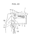
- the still camera 1 can be held only in the right hand 300 for photographing as shown in Figs. 9 and 10.
- a method of holding the still camera 1 with the slide cover 9 held at the open position only in the right hand 300 puts the thumb 301 to the rear wall 2b or the bottom wall 2d, puts the index finger 302 to the shutter button 16, places the middle finger 303 across the finger support part 5a and the upper end 9b of the slide cover 9, puts the third finger 304 on the strap lug 10, and puts the little finger 305 to the front wall 2a or the bottom wall 2d.
- Fig. 9 A method of holding the still camera 1 with the slide cover 9 held at the open position only in the right hand 300 puts the thumb 301 to the rear wall 2b or the bottom wall 2d, puts the index finger 302 to the shutter button 16, places the middle finger 303 across the finger support part 5a and the upper end 9b of the slide cover 9, puts the third finger
- the still camera 1 has the stepped or projecting finger support part 5a, the upper end 9b of the slide cover 9 and the strap lug 10. Therefore, the users fingers put to parts of the body 2 are prevented from slipping, the still camera 1 can be firmly held and the still camera 1 is handy.
- the middle finger 303 of the user holding the still camera 1 is placed across the front surface 4a of the right end section 4 of the body 2 and the front surface 9a of the slide cover 9. Since the front surface 4a of the right end section 4 and the front surface 9a of the slide cover 9 are gently curved continuous surfaces as mentioned above, the user can put the idle finger 303 across the front surface 4a of the right end section 4 of the body 2 and the front surface 9a of the slide cover 9 without feeling any wrong sensation.
- the front surface 4a of the right end section 4 of the body 2 and the front surface 9a of the slide cover 9 are supposed to be gently curved continuous surfaces in the foregoing description, the front surface 4a of the right end section 4 of the body 2 and the front surface 9a of the slide cover 9 may be continuous flat surfaces.
- the user can put the idle finger 303 across the front surface 4a of the right end section 4 of the body 2 and the front surface 9a of the slide cover 9 without feeling any wrong sensation even if the front surface 4a of the right end section 4 of the body 2 and the front surface 9a of the slide cover 9 are continuous flat surfaces.
- the display panel 11 is placed on the rear wall 2b of the body 2, and the shutter button 16 is placed on the top wall 2c. Therefore, an image displayed on the display panel 11 can be easily recognized and the finger can be easily put to the shutter button 16 when the still camera 1 is gripped by hands. Thus the visibility of the images on the display panel 1 l, and the operability and handiness of the still camera 1 are satisfactory.
- the strap lug 10 that serves also as a finger rest when the still camera 1 is held for photographing is formed on the right end section 4 of the front wall 2a of the body 2. Therefore, the strap lug 10 does not move when the slide cover 9 is moved and hence the still camera 1 can be stably gripped.
- the strap lug 10 serves also as a finger rest, the still camera 1 does not need any additional, special finger rest, which is effective in reducing the number of parts of the still camera 1 and in simplifying the construction of the still camera 1.
- the body 2 has a front panel 25, a rear panel 26 joined to the front panel 25, and a holding frame 27 interposed between the front panel 25 and the rear panel 26.
- a right end section of the rear panel 26 serves as a button holding part 26a.
- the button holding part 26a is provided with openings 26b for receiving the buttons.
- a button unit 28 is attached to the front surface of the button holding part 26a with, for example, an adhesive.
- the button unit 28 has an elongate, rectangular frame 29, a connecting member 30 connecting right and left side members of the frame 29, elastic tongues 31 extending obliquely upward from a middle part of the connecting member 30, the zoom button 12 attached to the upper ends of the elastic tongues 31, an upper mounting lug 32 projecting downward from a middle part of the connecting member 30, elastic arms 33 projecting inward from predetermined parts of the frame 29, respectively, the buttons 15 attached to the free ends of the elastic arms 33, respectively, and a lower mounting lug 34 projecting upward from the lower end member of the frame 29.
- the button unit 28 including those members is made by molding a resin.
- the outside surface of the button unit 28 is finished by a plating process.
- the mounting lugs 32 and 34 are provided with holes 32a and 34a, respectively.
- a compound push button built by combining the first push button module 13 and the second push button module 14 is placed in an opening formed in the frame 29 as shown in Figs. 11 and 12.
- the first push button module 13 has an annular operating button 35, four radial projections 36 arranged at equal angular intervals on and projecting from the circumference of the annular operating button 35, flexible parts 37 extending from the outer ends of the radial projections 36 substantially perpendicularly to the radial projections 36, respectively, and mounting parts 38 connected to the free ends of the flexible parts 37, respectively.
- the first push button module 13 having those members is formed by molding a resin.
- the outside surface of the first push button module 13 is finished by a plating process.
- the annular operating button 35 of the first push button module 13 is provided with a central opening 35a.
- the two diametrically opposite radial projections 36 are provided with backward projecting pins 36a, respectively.
- Each of the flexible members 37 has a circular part 37a extending along the circumference of the annular operating button 35, and a straight part 37b vertically extending from the free end of the circular part 37a.
- the straight parts 37b of the adjacent flexible parts 37 extend parallel to each other, and the free ends of the same straight parts 37b are connected to the mounting parts 38.
- the mounting parts 38 are provided with forward projecting pins 38a.
- the second push button module 14 has a central operating button 39, flexible legs 40 extending outward from the circumference of the central operating button 39, and connecting parts 41 connected to the free ends of the flexible legs 40.
- the second push button module 14 having those parts is formed by molding a resin.
- the outside surface of the second push button module 14 is finished by a plating process.
- the central operating button 39 formed in a substantially cylindrical shape has an operating part 39a, and a flange 39b connected to the inner end of the operating part 39a.
- the flexible legs 40 have diametrically opposite base parts 40a projecting radially outward from the flange 39b, substantially circular curved parts 40b extending from the free ends of the base parts 40a, respectively, along the circumference of the flange 39b, and end parts 40c extending from the curved parts 40b in opposite directions, respectively.
- the connecting parts 41 are provided with openings 41 a, respectively.
- the connecting parts 41 project in a circumferential direction from the end parts 40c, respectively.
- the first push button module 13 and the second push button module 14 are combined by a method which will be described below with reference to Figs. 13 to 17.
- the operating part 39a of the second push button module 14 is fitted in the central opening 35a of the annular operating button 35 of the first push button module 13.
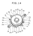
- the second push button module 14 is turned about the axis of the central operating button 39 to move the connecting parts 41 toward the pins 36a as shown in Fig. 14.
- the second push button module 14 is turned further, the flexible legs 40 are bent elastically forward, and the connecting parts 41 are brought into alignment with the pins 36a, respectively as shown in Fig. 15.
- first push button module 13 and the second push button module 14 are combined completely as shown in Figs. 16 and 17.
- the pins 36a of the first push button module 13, and the openings 41a of the legs 41 of the second push button module 14 are first and second connecting parts, respectively.
- the pins 38a of the mounting parts 38 of the first push button module 13 are fitted in the holes 32a and 34a of the mounting lugs 32 and 34 of the button unit 28 from behind the mounting lugs 32 and 34, respectively.
- the compound push button of the first push button module 13 and the second push button module 14 is attached to the button unit 28.
- the button unit 28 is attached to the front surface of the button holding part 26a with an adhesive or the like.
- the mounting parts of the first push button module 13 are held between the mounting lug 32 of the button unit 28 and the front surface of the button holding part 26a and between the mounting lug 34 of the button unit 28 and the front surface of the button holding part 26a, respectively, to hold the compound push button of the first push button module 13 and the second push button module 14 on the button holding part 26a.
- the zoom button 12 When the compound push button of the first push button module 13 and the second push button module 14 is thus held on the button holding part 26a, the zoom button 12, the annular operating button 35 of the first push button module 13, the central operating button 39 of the second push button module 14 and the operating buttons 15 are received in the openings 26b of the button holding part 26a, respectively, so as to protrude rearward from the button holding part 26a.
- a wiring board provided with a switching circuit is disposed at a position in front of the button unit 28 in the body 2.
- the wiring board is provided with switches respectively corresponding to the zoom button 12, the first push button module, the second push button module 14 and the operating buttons 15.
- the zoom switch is operated to actuate a zooming function.
- the annular operating button 35 of the first push button 35 is pressed, the flexible parts 37 are elastically deformed and the switch corresponding to the pressed part of the annular operating button 35 is closed to actuate a desired function, such as a flash photographing function.
- the central operating button 39 of the second push button module 14 is pressed, the flexible legs 40 are elastically deformed and the switch corresponding to the central operating button 39 is closed to actuate a predetermined function assigned to the central operating button 39.
- a predetermined function such as a menu displaying function, assigned to the operating button 15 is actuated.
- the first push button module 13 and the second push button module 14 are combined by elastically warping the flexible legs 40 of the second push button module 14 in a direction in which the central operating button 39 of the second push button module 14 is fitted in the central opening 35a, and fitting the pins 36a of the radial projections 36 of the first push button module 13 in the openings 41a of the connecting parts 41 of the second push button module 14.
- the first push button module 13 and the second push button module 14 do not need to be welded together, can be combined by simple combining work in a short time.
- the first push button module 13 and the second push button module 14 When the first push button module 13 and the second push button module 14 are plated, the first push button module 13 and the second push button module 14 cannot be connected by welding because metal films coating the first push button module 13 and the second push button module 14 do not melt.
- the surfaces of the first push button module 13 and the second push button module 14 can be finished by a plating process when the first push button module 13 and the second push button module 14 are thus combined by fitting the pins 36a of the radial projections 36 of the first push button module 13 in the openings 41 a of the connecting parts 41 of the second push button module 14.
- fine, concentric, circular grooves s can be formed in the rear end surfaces of the annular operating button 35 of the first push button module 13 and the central operating button 39 of the second push button module 14 as shown in Fig. 16 by a spin patterning process to provide the same surfaces with a decorative appearance.
- the pins 36a are first connecting parts, and the connecting parts 41 provided with the openings 41 a are second connecting parts, and the first push button module 13 and the second push button module 14 are combined by fitting the pins 36a in the openings 41a.
- the first push button module 13 and the second push button module 14 can be easily combined.
- the connecting parts 41 are pressed against the projections 36 of the first push button module 13 by the resilience of the flexible legs 40 of the second push button module 14 as shown in Fig. 17 when the first push button module 13 and the second push button module 14 are combined. Therefore, the first push button module 13 and the second push button module 14 do not shake and can be stably combined.
- the first push button module 13 is provided with the pins 36a and the second push button module 14 is provided with the connecting parts 41 provided with the openings 41a.
- the openings may be formed in the first push button module 13 and the pins may be formed in the second push button module 14 to combine the first push button module 13 and the second push button module 14.
- the pins and the connecting parts provided with the openings are used to combine the first push button module 13 and the second push button module 14.
- Projections may be formed in the first push button module 13 (the second push button module) and recesses may be formed in the second push button module 14 (the first push button module 13), and the first push button module 13 and the second push button module 14 may be combined by fitting the projections in the recesses, respectively.
- Hooks may be formed in the first push button module 13 and the second push button module 14, and the hooks may be engaged to combine the first push button module 13 and the second push button module 14.
- the body 2 is provided with a cavity 22 opening in the right side wall 2f of the body 2.
- a battery locking member 42 is supported so as to be turnable on the lower edge of the holding frame 27 of the body 2 at the open end of the cavity 22 as shown in Fig. 7.
- Two locking projections 27a are formed at upper and lower positions, respectively, on each of a front side member and a rear side member of the holding frame 27 at the open end of the cavity 22. Only the locking projections 27a formed on the rear side member of the holding frame 27 are shown in Fig. 7.
- Vertically elongate slots 43 are formed in upper parts of the front and the rear side member of the holding frame 27, respectively, above the open end of the cavity 22 as shown in Fig. 18. The slots 43 penetrate the front and the rear side member in a direction parallel to the optical axis of the still camera 1.
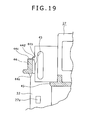
- a vertically elongate stopping projection 44 is formed at an upper position of the right end part of the holding frame 27 as shown in Figs. 18 and 19.
- the stopping projection 44 has a lower end surface serving as a stopping surface 44a, a left side surface serving as a first retaining surface 44b, and an upper end surface serving as a second retaining surface 44c.
- An inclined surface 44d sloping obliquely upward so as to incline to the right extends between the first retaining surface 44b and the second retaining surface 44c of the stopping projection 44.
- a vertical through hole 45 is formed between the open end of the cavity 22 and the stopping projection 44 in the holding frame 27.
- a swing lid 24 for covering the open end of the cavity 22 has an upper end part connected to the body 2 such that the swing lid 24 can turn on the body 2 as shown in Figs 3, 5 and 7.
- the swing lid 24 has a lid body 46 and a projection 47, which are formed integrally in a unitary member.
- Two L-shaped catching parts 46a project forward or rearward from the front side surface of the lid body 46 and are vertically spaced apart.
- Two L-shaped catching parts 46a project forward or rearward from the rear side surface of the lid body 46 and are vertically spaced apart.
- the projection 47 projects upward from a left half part of the upper end surface of the lid body 46.
- the upper end surface 46b of the lid body 46 is a stopping surface.
- the projection 47 has front and rear arms 48.
- the arms 48 are provided with through holes 48a, respectively.
- the through holes 48a extend in a direction parallel to the optical axis of the still camera 1.
- a surface of the projection 47 facing the right side wall 2f of the body 2 is provided with a spring retaining part 47a for retaining a coil spring 49.
- the coil spring 49 is disposed between the tongues 48.
- the coil spring 49 has a coil body 50, a first arm 51 extending from one of the opposite ends of the coil body 50, and a second arm 52 extending from the other end of the coil body 50.
- the respective end parts 51a and 52a of the arms 51 and 52 are bent substantially at right angles.
- the swing lid 24 is supported for turning on the body 2 by a support shaft 53.
- the support shaft 53 is passed forward through a slot 43 formed in a rear part of the holding frame 27, the through hole 48a formed in a rear part of the swing lid 24, the coil body 50 of the coil spring 49, the through hole 48a formed in a front part of the swing lid 24, and a slot 43 formed in a front part of the holding frame 27 in that order.
- the support shaft 53 can move vertically in the slots 43.
- the swing lid 24 can turn on the support shaft 53. When the support shaft 53 is moved vertically in the slots 43, the swing lid 24 moves vertically relative to the body 2 together with the support shaft 53.
- An upper limit position in a moving range of the swing lid 24 on the body 2 is an unturnable position where the swing lid 24 cannot turn, and a lower limit position in the moving range of the swing lid 24 on the body 2 is a turnable position where the swing lid 24 can turn.
- the first arm 51 of the coil spring 49 is elastically pressed against the spring retaining part 47a of the projection 46 from the left side, and the second arm 52 of the coil spring 49 is elastically pressed against the second retaining surface 44c, the inclined surface 44d or the first retaining surface 44b of the stopping projection 44 depending on the position of the swing lid 24 relative to the body 2.
- the second arm 52 slides on the stopping projection 44 between the second retaining surface 44c and the first retaining surface 44b as the position of the swing lid 24 relative to the body changes.
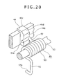
- a front part of the end part 52a of the second arm 52 bent at right angles projects forward from the stopping projection 44 as shown in Fig. 20. Therefore, the tip of the second arm 52 does not touch the stopping projection 44 when the second arm 52 slides on the stopping projection 44 between the second retaining surface 44c and the first retaining surface 44b and hence the stopping projection 44 will not be scratched by the stopping projection 44.
- the second arm 52 of the coil spring 49 slides from the second retaining surface 44c of the stopping projection 44 past the inclined surface 44d onto the first retaining surface 44b.
- the support shaft 53 supporting the swing lid 24 slides down in the slots 43.
- the swing lid 24 reaches the lower limit position, namely, the turnable position.
- the catching parts 46c of the swing lid 24 are disengaged from the locking projections 47a, and the first arm 51 of the coil spring 49 applies a rightward force as indicated by the arrow M in Fig. 22.
- the swing lid 24 is turned relative to the body 2 on the support shaft 53 by the resilience of the coil spring 49 as shown in Fig. 23.
- the swing lid 24 is turned until the projection 47 comes into contact with the stopping surface 44a of the stopping projection 44 as shown in Fig. 24.
- the cavity 22 is opened and the rechargeable battery 23 can be taken out from the cavity 22.
- the rechargeable battery 23 held in the cavity 22 is locked in place by the battery locking member 42.
- the battery locking member 42 is turned to unlock the rechargeable battery 23, and then the rechargeable battery 23 can be taken out from the cavity 22.
- the battery locking member 42 is turned in a direction in which the same is turned to unlock the storage batter 23.
- the battery locking member 42 is turned in the reverse direction after the rechargeable battery 23 has been received in the cavity 22 to lock the rechargeable battery 23 in place in the cavity 22.
- the swing lid 24 is turned in the closing direction to the turnable position as shown in Fig. 25. Then, the swing lid 24 is pushed upward to slide the swing lid 24 upward on the body 2 to a position shown in Fig. 26.
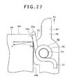
- the arm 52 moves from the first retaining surface 44b to the inclined surface 44d on the stopping projection 44 as shown in Fig. 27 and the second arm 52 is pressed against the inclined surface 44d by the resilience of the coil spring 49.
- the force P acts obliquely downward as indicated by the arrow in Fig. 27.
- the force P can be decomposed into a horizontal component force and a vertical component force P d .
- An upward force F u corresponding to a reaction force equal to the vertical component force P d acts on the second arm 52.
- the second arm 52 is pushed upward by the upward force F u .
- the swing lid 24 is moved upward automatically by the upward force F u after the user's finger has been removed from the swing lid 24.
- the second arm 52 comes into contact with the boundary between the second retaining surface 44c and the inclined surface 44d as shown in Fig. 28.
- the vertical component force P d increases and hence the upward force F u increases.
- the increased upward force F u moves the swing lid 24 to the unturnable position shown in Fig. 21, the second arm 52 of the coil spring 49 is pressed against the second retaining surface 44d of the stopping projection 44, and the upper end surface 46b of the lid body 46 is brought into contact with the stopping surface 44a of the stopping projection 44.
- the swing lid 24 is restrained from turning relative to the body 2.
- the locking projections 27a of the holding frame 27 engage with the catching parts 46a of the swing lid 24 to hold the swing lid 24 at the unturnable position.
- the swing lid structure of the still camera 1 is simple because the swing lid 24 is supported on the body 2 by the support shaft 53 so as to be slidable and turnable relative to the body 2.
- the coil spring 49 exerts the upward force F u on the swing lid 24 to slide the swing lid 24 from the turnable position to the unturnable position.
- the user does not need to move the swing lid 24 from the turnable position to the unturnable position entirely by a manual operation, which improves the handiness of the still camera 1.
- the swing lid structure Since the coil spring 49 exerts the upward force F u to move the swing lid 24 from the turnable position to the unturnable position, the swing lid structure is simple and the mechanism of the still camera 1 is simple, which reduces the manufacturing cost of the still camera 1.
- the stopping projection 44 that restrains the swing lid 24 at the unturnable position from turning has the first retaining surface 44b and the second retaining surface 44c for retaining the first arm 52 of the coil spring 49. Therefore, the swing lid structure does not need to have two separate parts respectively for restraining the swing lid 24 at the unturnable position from turning and retaining the second arm 52 of the coil spring 49, which simplifies the swing lid structure.
- the lid can be slid from the unturnable position to the turnable position by a small force and the upward force F u can be applied to the swing lid 24 at an early stage of sliding the swing lid 24 from the turnable position to the unturnable position.
- the inclined surface 44d is formed on the stopping projection 44 to apply the upward force F u top the swing lid 24 as mentioned above, the upward force F u can be applied to the swing lid 24 even if the stopping member 44 does not have the inclined surface 44d.
- an upward force F u corresponding to a downward component force P d start acting on the swing lid 24 upon the rise of the end part 52a of the second arm 52 of the coil spring 49 past the edge where the first retaining surface 44b and the second retaining surface 44c meet.
Landscapes
- General Physics & Mathematics (AREA)
- Engineering & Computer Science (AREA)
- Physics & Mathematics (AREA)
- General Chemical & Material Sciences (AREA)
- Microelectronics & Electronic Packaging (AREA)
- Chemical & Material Sciences (AREA)
- Chemical Kinetics & Catalysis (AREA)
- Electrochemistry (AREA)
- Mechanical Engineering (AREA)
- Studio Devices (AREA)
- Casings For Electric Apparatus (AREA)
- Blocking Light For Cameras (AREA)
- Camera Bodies And Camera Details Or Accessories (AREA)
- Structure And Mechanism Of Cameras (AREA)
Abstract
Description
- The present invention relates to a swing lid structure and an electronic apparatus.
- Electronic apparatuses include, for example, video cameras, still cameras, television receivers, cellular telephones, audio devices and such. Some of those electronic apparatuses have a body provided with a cavity for holding a predetermined part, such as a rechargeable battery.
- A cavity defined in a body included in an electronic apparatus disclosed in, for example,
JP-UM-A-2-113895 JP-UM-A-2-113895 - In this known electronic apparatus, the swing lid has the cover body and the connecting member, the connecting member is supported on the body so as to be turnable relative to the body, and the cover body is supported on the connecting member so as to be slidable on the connecting member. Thus a mechanism including the swing lid and the body is inevitably complicated. A connecting member making process that bends the metal sheet in the predetermined shape is troublesome
- Accordingly, it is desirable to provide a simple supporting structure, for supporting a swing lid on an electronic apparatus, capable of solving the forgoing problems.
- Various respective aspects and features of the invention are defined in the appended claims. Features from the dependent claims may be combined with features of the independent claims as appropriate and not merely as explicitly set out in the claims.
- Embodiments of the invention provide a technique for simplifying a swing lid structure including a swing lid rotatably and slidably supported on a body.
- To address the foregoing problems, a first embodiment of the present invention is directed to a swing lid structure including: a body having a cavity for holding a predetermined part therein and provided with slots extending in a predetermined direction; a swing lid provided with through holes and capable of covering the cavity of the body; and a support shaft passed through the through holes of the swing lid and slidably fitted in the slots of the body; wherein the swing lid can slide on the body as the support shaft moves in the slots and can turn on the support shaft relative to the body.
- To address the foregoing problems, a second embodiment of the present invention is directed to an electronic apparatus including: a body having a cavity for holding a predetermined part therein and provided with slots extending in a predetermined direction; a swing lid provided with through holes and capable of covering the cavity of the body; and a support shaft passed through the through holes of the swing lid and slidably fitted in the slots of the body; wherein the swing lid can slide on the body as the support shaft moves in the slots and can turn on the support shaft relative to the body.
- In each of the swing lid structure and the electronic apparatus, the swing lid can slide together with the support shaft relative to the body.
- The swing lid structure of the first aspect includes the body defining the cavity for holding a predetermined part therein and provided with the slots extending in a predetermined direction, the swing lid provided with the through holes and capable of covering the cavity of the body, and the support shaft passed through the through holes of the swing lid and slidably fitted in the slots of the body, and the swing lid can slide on the body as the support shaft moves in the slots, and can turn on the support shaft relative to the body.
- The swing lid structure in which the swing lid is supported by the support shaft on the body so as to be slidable and turnable relative to the body is simple.
- In a swing lid structure in the first aspect, the swing lid may be slidable between a first position where the swing lid can turn relative to the body and a second position where the swing lid can not turn relative to the body, a coil spring having a coil and first and second arms extending from the opposite ends of the coiled spring body, respectively, may be put on the support shaft, the swing lid may be provided with a spring retaining part against which the first arm of the coil spring is pressed, and the body may be provided with a stopping projection having a first retaining surface against which the second arm of the coil spring is pressed at least when the swing lid is at the first position, and a second retaining surface against which the second arm of the coil spring is pressed when the swing lid is at the second position so as to push the swing lid toward the first position. Thus the operator does not need to perform all the operations necessary for moving the swing lid from the first position where the swing lid is turnable to the second position where the swing lid is unturnable, which facilitates using a device provided with this swing lid structure.
- In a swing lid structure in the first embodiment, the stopping projection of the body may have a restraining surface for restraining the swing lid at the second position from turning, and the first and the second retaining surface may be formed on the stopping projection. Thus the restraining surface for restraining the swing lid from turning and the retaining surfaces for bearing the second arm of the coil spring do not need to be formed separately, which simplifies the swing lid structure.
- In a swing lid structure in the first embodiment, the first and the second retaining surface may be formed so as to extend perpendicularly to each other, and an inclined surface inclined to both the first and the second retaining surface may be extended between the first and the second retaining surface such that the second arm slide along the inclined surface when the swing lid slides relative to the body. Thus the swing lid can be moved by a small force to slide the swing lid from the second position toward the first position, and a moving force can be applied at an early stage of sliding the swing lid when the swing lid is slid from the first position toward the second position.
- The electronic apparatus according to the second embodiment includes: the body provided with the slots extending in a predetermined direction; the swing lid provided with the through holes, and the support shaft passed through the through holes of the swing lid and slidably fitted in the slots of the body, and the swing lid can slide on the body as the support shaft moves in the slots can turn on the support shaft relative to the body.
- Since the swing lid is supported by the support shaft on the body so as to be slidable and turnable relative to the body, the electronic apparatus is simple in construction.
- The invention will now be described by way of example with reference to the accompanying drawings, throughout which like parts are referred to by like references, and in which:
- Fig. 1 is a perspective view of a still camera in a preferred embodiment with its slide cover at a closed position;
- Fig. 2 is a perspective view of the still camera shown in Fig. 1 with its slide cover at an open position;
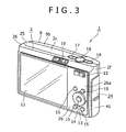
- Fig. 3 is a perspective view of the still camera shown in Fig. 1, showing the back of the still camera;
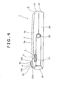
- Fig. 4 is an enlarged bottom view of the still camera shown in Fig. 1;
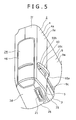
- Fig. 5 is an enlarged perspective view of a part of the still camera shown in Fig. 1;
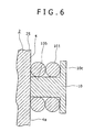
- Fig. 6 is an enlarged sectional view of a strap lug and a strap wound round the strap lug;
- Fig. 7 is a perspective view of the still camera shown in Fig. 1 and a rechargeable battery removed from the still camera;
- Fig. 8 is a perspective view of the still camera shown in Fig. 1 in use;
- Fig. 9 is a front elevation of the still camera shown in Fig. 1 held by hand in a first holding manner;
- Fig. 10 is a front elevation of the still camera shown in Fig. 1 held by hand in a second holding manner;
- Fig. 11 is an enlarged, exploded perspective view of a button holding unit, a first push button module, a second push button module, and a button unit;
- Fig. 12 is an enlarged perspective view of the button holding unit, the first push button module, the second push button module and the button unit;
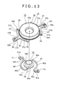
- Fig. 13 is an enlarged perspective view of the fist and the second push button module separated from each other;
- Fig. 14 is an enlarged perspective view of assistance in explaining a method of combining the first and the second push button module;
- Fig. 15 is an enlarged sectional view of the first and the second push button module at a stage before a connecting pin included in the first push button module is inserted into a connecting hole of the second push button module;
- Fig. 16 is an enlarged perspective view of a compound push button built by combining the first and the second push button module;
- Fig. 17 is an enlarged sectional view of the first and the second push button module at a stage after the connecting pin of the first push button module is inserted into the connecting hole of the second push button module;
- Fig. 18 is an enlarged, exploded perspective view of a holding frame, a swing lid, a support shaft and a coil spring;
- Fig. 19 is an enlarged sectional view of the holding frame shown in Fig. 18;
- Fig. 20 is an enlarged perspective view of the coil spring shown in Fig. 18 with its second arm in contact with a restraining part;
- Fig. 21 is an enlarged sectional view of assistance in explaining operations of the swing lid, in which the swing lid is at a second position where the swing lid is unturnable;
- Fig. 22 is an enlarged sectional view of assistance in explaining operations of the swing lid, in which the swing lid has been moved from the second position to a first position where the swing lid is turnable;
- Fig. 23 is an enlarged sectional view of assistance in explaining operations of the swing lid, in which the swing lid placed at the first position is being turned;
- Fig. 24 is an enlarged sectional view of assistance in explaining operations of the swing lid, in which the swing lid has been turned to open a space in a body;
- Fig. 25 is an enlarged sectional view of assistance in explaining operations of the swing lid, in which the swing lid has been completely turned;
- Fig. 26 is an enlarged sectional view of assistance in explaining operations of the swing lid, in which the swing lid is being moved from the first position to the second position;
- Fig. 27 is a typical view of assistance in explaining a force that may be generated while the swing lid is being moved from the first position to the second position;
- Fig. 28 is a typical view of assistance in explaining a force that may be generated while the swing lid is being moved from the first position to the second position; and
- Fig. 29 is a typical view of assistance in explaining a force that may be generated while the swing lid is being moved from the first position to the second position when the retaining part is not provided with a slope.
- Embodiments of the present invention will be described as applied to a still camera by way of example. The present invention is not limited in its practical application to the still camera specifically described herein and is applicable widely to various devices including video cameras. In the following description, vertical directions and transverse directions are those as a user looks when the user uses the still camera for photographing. For example, the user is on the rear side of the still camera and an object is on the front side of the still camera. Vertical directions and transverse directions are used for convenience in the following description and do not place any restrictions on the embodiments of the present invention.
- Referring to Figs. 1 to 3, a
still camera 1 has abody 2 holding component parts therein. Thebody 2 is formed in a shape substantially resembling a flat, transversely elongate, rectangular solid. Thebody 2 has afront wall 2a, arear wall 2b, atop wall 2c, abottom wall 2d, aleft side wall 2e and aright side wall 2f. As shown in Figs. 1 and 2, the surface of thefront wall 2a, excluding the surface of aright end section 4, is depressed to form arecess 3. The respective surfaces of therecess 3 and theright end section 4 are connected by a verticallyelongate boundary surface 5 facing obliquely leftward. Alens 6, a built-inflash 7 and a self-timer lens 8 are arranged in an upper end part of therecess 3. - A
slide cover 9 is vertically slidably supported on the surface of therecess 3. Theslide cover 9 has a height lower than that of thebody 2, and a width equal to that of therecess 3. Theslide cover 9 has a forward convex, gently curvedfront surface 9a, a flatupper surface 9b and a flatlower surface 9c. Theright end section 4 has a forward convex, gently curvedfront surface 4a of a curvature equal to that of thefront surface 9a of theslide cover 9. Thus thefront surface 4a of theright end section 4 is smoothly continuous with thefront surface 9a of theslide cover 9 as shown in Fig. 4. - The
upper surface 9b of theslide cover 9 is flush with theupper surface 2c of thebody 2 when theslide cover 9 is positioned at an upper closed position as shown in Fig. 1 to cover thelens 6, the built-inflash 7 and the self-timer lens 8. Thelower surface 9c of theslide cover 9 is flush with thelower surface 2d of thebody 2 as shown in Fig. 2 when theslide cover 9 is positioned at a lower open position to uncover thelens 6, the built-inflash 7 and the self-timer lens 8. An electric circuit included in the stillcamera 1 is connected to a power source when theslide cover 9 is slid from the closed position to the open position. The electric circuit of thestill camera 1 is disconnected from the power source when theslide cover 9 is slid from the open position to the closed position. An upper part, which serves as afinger support part 5a, of the verticallyelongate boundary surface 5 of thebody 2 is exposed as shown in Fig. 2 when theslide cover 9 is moved to the open position. The user's finger is put to thefinger support part 5a when the user holds the stillcamera 1 for photographing. - A
strap lug 10 protrudes forward from a lower end part of theright end section 4. As shown in Fig. 5, thestrap lug 5 has aprotrusion 10a protruding forward from a left end part of theright end section 4, astrap peg 10b protruding forward from a right end part of theright end section 4, and astopper 10c extending between the respective front ends of theprotrusion 10a and thestrap peg 10b. Theprotrusion 10a, thestrap peg 1 0b and thestopper 10c are formed integrally. Thestopper 10c over hangs thestrap lug 1 0b entirely from the front side as shown in Fig. 6. Oneend part 101 of astrap 100 is wound round thestrap peg 10b. Since thestopper 10c overhangs thestrap peg 10b entirely, theend part 101 wound round thestrap lug 10b is held behind thestopper 10c as shown in Fig. 6. - Referring to Fig. 3, a
display panel 11, such as a liquid crystal display panel, is fitted in a left section of therear wall 2b of thebody 2. Azoom button 12 is disposed at a position near the upper end of a right section of therear wall 2b. A firstpush button module 13 and a secondpush button module 14 are disposed at a position near the lower end of the right section of therear wall 2b.Operating buttons 15 are arranged around the firstpush button module 13. A right part of thezoom button 12 is pressed for wide-angle photography, and a left part of thezoom button 12 is pressed for telephotography. The firstpush button module 13 has an annular shape. An upper part, a lower part, a right part and a left part of the firstpush button module 13 are pressed selectively to select a desired one of various modes including a flash photographing mode, a self-timer photographing mode, a photographed image display mode and a close-up photographing mode (macrophtographing mode). The secondpush button module 14 is fitted in the central opening of the firstpush button module 13. The secondpush button module 14 is pressed to execute a mode selected by pressing the firstpush button module 13. Thepush buttons 15 are operated to execute operations for displaying various menus, changing pictures displayed on thedisplay panel 11, deleting photographed images and slide show. - A
shutter button 16 is disposed at a part of thetop wall 2c of thebody 2 near the right end of thetop wall 2c. Theshutter button 16 is depressed for still photography and motion picture photography. On thetop wall 2c of thebody 2, amain switch button 17 is disposed on the left side of theshutter button 16 and a camera-shake prevention button 18 is disposed on the right side of theshutter button 16. When themain switch 17 is depressed repeatedly, the power source is alternately connected to and disconnected from the electric circuit of thestill camera 1. When the camera-shake prevention button 18 is depressed, a camera-shake preventing function is actuated. - The power source is connected to the electric circuit when the
slide cover 9 is slid from the closed position to the open position. The power source is disconnected from the electric circuit when theslide cover 9 is slid from the open position to the closed position. - A
slide key 19 is disposed on a rear end part of thetop wall 2c. Theslide key 19 is a selector key for selecting a still picture photographing mode, a motion picture photographing mode or an image reproducing mode. - Referring to Fig. 4, a
tripod connecting hole 20 and aconnector 21 are arranged on thebottom wall 2d of thebody 2. Thetripod connecting hole 20 is used for connecting the stillcamera 1 to a tripod. Theconnector 21 is used for connecting the stillcamera 1 to an external device, such as a printer. - Referring to Fig. 7, the
body 2 is provided with acavity 22 opening in theright side wall 2f of thebody 2. Arechargeable battery 23 is held in thecavity 22. Thecavity 22 is covered with aswing lid 24. - The user holds the still
camera 1 in theleft hand 200 and theright hand 300 for photographing as shown in Fig. 8. The stillcamera 1 can be held only in theright hand 300 for photographing as shown in Figs. 9 and 10. As shown in Fig. 9, A method of holding the stillcamera 1 with theslide cover 9 held at the open position only in theright hand 300 puts thethumb 301 to therear wall 2b or thebottom wall 2d, puts theindex finger 302 to theshutter button 16, places themiddle finger 303 across thefinger support part 5a and theupper end 9b of theslide cover 9, puts thethird finger 304 on thestrap lug 10, and puts thelittle finger 305 to thefront wall 2a or thebottom wall 2d. As shown in Fig. 10, another method of holding the stillcamera 1 with theslide cover 9 held at the open position only in theright hand 300 puts thethumb 301 to therear wall 2b or thebottom wall 2d, puts theindex finger 302 to theshutter button 16, places themiddle finger 303 across thefinger support part 5a and theupper end 9b of theslide cover 9, bends thethird finger 304, puts the bentthird finger 304 on thestrap lug 10, bends thelittle finger 305, and puts the bent little finger to thefront wall 2a or thebottom wall 2d. Even if thestrap 100 is attached to thestrap lug 10, the end part of the 101 of thestrap 100 will not interfere with the user's finger and the user can comfortably grip the stillcamera 1 because theend part 101 of thestrap 100 is held behind thestopper 10c. Thus thestrap lug 10 serves also as a finger rest. - The still
camera 1 has the stepped or projectingfinger support part 5a, theupper end 9b of theslide cover 9 and thestrap lug 10. Therefore, the users fingers put to parts of thebody 2 are prevented from slipping, the stillcamera 1 can be firmly held and the stillcamera 1 is handy. - In some cases, the
middle finger 303 of the user holding the stillcamera 1 is placed across thefront surface 4a of theright end section 4 of thebody 2 and thefront surface 9a of theslide cover 9. Since thefront surface 4a of theright end section 4 and thefront surface 9a of theslide cover 9 are gently curved continuous surfaces as mentioned above, the user can put theidle finger 303 across thefront surface 4a of theright end section 4 of thebody 2 and thefront surface 9a of theslide cover 9 without feeling any wrong sensation. - Although the
front surface 4a of theright end section 4 of thebody 2 and thefront surface 9a of theslide cover 9 are supposed to be gently curved continuous surfaces in the foregoing description, thefront surface 4a of theright end section 4 of thebody 2 and thefront surface 9a of theslide cover 9 may be continuous flat surfaces. The user can put theidle finger 303 across thefront surface 4a of theright end section 4 of thebody 2 and thefront surface 9a of theslide cover 9 without feeling any wrong sensation even if thefront surface 4a of theright end section 4 of thebody 2 and thefront surface 9a of theslide cover 9 are continuous flat surfaces. - In the
still camera 1, thedisplay panel 11 is placed on therear wall 2b of thebody 2, and theshutter button 16 is placed on thetop wall 2c. Therefore, an image displayed on thedisplay panel 11 can be easily recognized and the finger can be easily put to theshutter button 16 when the stillcamera 1 is gripped by hands. Thus the visibility of the images on the display panel 1 l, and the operability and handiness of thestill camera 1 are satisfactory. - The
strap lug 10 that serves also as a finger rest when the stillcamera 1 is held for photographing is formed on theright end section 4 of thefront wall 2a of thebody 2. Therefore, thestrap lug 10 does not move when theslide cover 9 is moved and hence the stillcamera 1 can be stably gripped. - Since the
strap lug 10 serves also as a finger rest, the stillcamera 1 does not need any additional, special finger rest, which is effective in reducing the number of parts of thestill camera 1 and in simplifying the construction of thestill camera 1. - Referring to Fig. 3, the
body 2 has afront panel 25, arear panel 26 joined to thefront panel 25, and a holdingframe 27 interposed between thefront panel 25 and therear panel 26. As shown in Fig. 11, a right end section of therear panel 26 serves as abutton holding part 26a. Thebutton holding part 26a is provided withopenings 26b for receiving the buttons. Abutton unit 28 is attached to the front surface of thebutton holding part 26a with, for example, an adhesive. Thebutton unit 28 has an elongate,rectangular frame 29, a connectingmember 30 connecting right and left side members of theframe 29,elastic tongues 31 extending obliquely upward from a middle part of the connectingmember 30, thezoom button 12 attached to the upper ends of theelastic tongues 31, an upper mountinglug 32 projecting downward from a middle part of the connectingmember 30,elastic arms 33 projecting inward from predetermined parts of theframe 29, respectively, thebuttons 15 attached to the free ends of theelastic arms 33, respectively, and a lower mountinglug 34 projecting upward from the lower end member of theframe 29. Thebutton unit 28 including those members is made by molding a resin. The outside surface of thebutton unit 28 is finished by a plating process. The mounting lugs 32 and 34 are provided withholes push button module 13 and the secondpush button module 14 is placed in an opening formed in theframe 29 as shown in Figs. 11 and 12. - Referring to Figs. 13 and 14, the first
push button module 13 has anannular operating button 35, fourradial projections 36 arranged at equal angular intervals on and projecting from the circumference of theannular operating button 35,flexible parts 37 extending from the outer ends of theradial projections 36 substantially perpendicularly to theradial projections 36, respectively, and mountingparts 38 connected to the free ends of theflexible parts 37, respectively. The firstpush button module 13 having those members is formed by molding a resin. The outside surface of the firstpush button module 13 is finished by a plating process. Theannular operating button 35 of the firstpush button module 13 is provided with acentral opening 35a. The two diametrically oppositeradial projections 36 are provided with backward projectingpins 36a, respectively. Each of theflexible members 37 has acircular part 37a extending along the circumference of theannular operating button 35, and astraight part 37b vertically extending from the free end of thecircular part 37a. Thestraight parts 37b of the adjacentflexible parts 37 extend parallel to each other, and the free ends of the samestraight parts 37b are connected to the mountingparts 38. The mountingparts 38 are provided with forward projectingpins 38a. - Referring to Fig. 13, the second
push button module 14 has acentral operating button 39,flexible legs 40 extending outward from the circumference of thecentral operating button 39, and connectingparts 41 connected to the free ends of theflexible legs 40. The secondpush button module 14 having those parts is formed by molding a resin. The outside surface of the secondpush button module 14 is finished by a plating process. Thecentral operating button 39 formed in a substantially cylindrical shape has anoperating part 39a, and aflange 39b connected to the inner end of the operatingpart 39a. Theflexible legs 40 have diametricallyopposite base parts 40a projecting radially outward from theflange 39b, substantially circularcurved parts 40b extending from the free ends of thebase parts 40a, respectively, along the circumference of theflange 39b, and endparts 40c extending from thecurved parts 40b in opposite directions, respectively. The connectingparts 41 are provided withopenings 41 a, respectively. The connectingparts 41 project in a circumferential direction from theend parts 40c, respectively. - The first
push button module 13 and the secondpush button module 14 are combined by a method which will be described below with reference to Figs. 13 to 17. First, the operatingpart 39a of the secondpush button module 14 is fitted in thecentral opening 35a of theannular operating button 35 of the firstpush button module 13. Then, the secondpush button module 14 is turned about the axis of thecentral operating button 39 to move the connectingparts 41 toward thepins 36a as shown in Fig. 14. The secondpush button module 14 is turned further, theflexible legs 40 are bent elastically forward, and the connectingparts 41 are brought into alignment with thepins 36a, respectively as shown in Fig. 15. Then, forces applied to theflexible legs 40 to bend theflexible legs 40 elastically are removed, and, consequently, thepins 36a are received in theopenings 41a of theflexible legs 41, respectively. Thus the firstpush button module 13 and the secondpush button module 14 are combined completely as shown in Figs. 16 and 17. Thepins 36a of the firstpush button module 13, and theopenings 41a of thelegs 41 of the secondpush button module 14 are first and second connecting parts, respectively. - In the compound push button thus built by combining the first
push button module 13 and the secondpush button module 14, the connectingparts 41 of the secondpush button module 14 are pressed against theradial projections 36 of the firstpush button module 13 by the resilience of theflexible legs 40 of the secondpush button module 14 as shown in Fig. 17. - Referring to Fig. 12, after the first
push button module 13 and the secondpush button module 14 have been combined, thepins 38a of the mountingparts 38 of the firstpush button module 13 are fitted in theholes button unit 28 from behind the mounting lugs 32 and 34, respectively. Thus the compound push button of the firstpush button module 13 and the secondpush button module 14 is attached to thebutton unit 28. After the compound push button of the firstpush button module 13 and the secondpush button module 14 has been thus attached to thebutton unit 28, thebutton unit 28 is attached to the front surface of thebutton holding part 26a with an adhesive or the like. After thebutton unit 28 has been thus fixed to the front surface of thebutton holding part 26a, the mounting parts of the firstpush button module 13 are held between the mountinglug 32 of thebutton unit 28 and the front surface of thebutton holding part 26a and between the mountinglug 34 of thebutton unit 28 and the front surface of thebutton holding part 26a, respectively, to hold the compound push button of the firstpush button module 13 and the secondpush button module 14 on thebutton holding part 26a. When the compound push button of the firstpush button module 13 and the secondpush button module 14 is thus held on thebutton holding part 26a, thezoom button 12, theannular operating button 35 of the firstpush button module 13, thecentral operating button 39 of the secondpush button module 14 and the operatingbuttons 15 are received in theopenings 26b of thebutton holding part 26a, respectively, so as to protrude rearward from thebutton holding part 26a. - A wiring board provided with a switching circuit is disposed at a position in front of the
button unit 28 in thebody 2. The wiring board is provided with switches respectively corresponding to thezoom button 12, the first push button module, the secondpush button module 14 and the operatingbuttons 15. - When the
zoom button 12 is pressed, theelastic tongues 31 of thebutton unit 28 are flexed elastically, the zoom switch is operated to actuate a zooming function. When theannular operating button 35 of thefirst push button 35 is pressed, theflexible parts 37 are elastically deformed and the switch corresponding to the pressed part of theannular operating button 35 is closed to actuate a desired function, such as a flash photographing function. When thecentral operating button 39 of the secondpush button module 14 is pressed, theflexible legs 40 are elastically deformed and the switch corresponding to thecentral operating button 39 is closed to actuate a predetermined function assigned to thecentral operating button 39. When each of the operatingbuttons 15 is pressed, a predetermined function, such as a menu displaying function, assigned to theoperating button 15 is actuated. - In the
still camera 1, the firstpush button module 13 and the secondpush button module 14 are combined by elastically warping theflexible legs 40 of the secondpush button module 14 in a direction in which thecentral operating button 39 of the secondpush button module 14 is fitted in thecentral opening 35a, and fitting thepins 36a of theradial projections 36 of the firstpush button module 13 in theopenings 41a of the connectingparts 41 of the secondpush button module 14. Thus the firstpush button module 13 and the secondpush button module 14 do not need to be welded together, can be combined by simple combining work in a short time. When the firstpush button module 13 and the secondpush button module 14 are plated, the firstpush button module 13 and the secondpush button module 14 cannot be connected by welding because metal films coating the firstpush button module 13 and the secondpush button module 14 do not melt. The surfaces of the firstpush button module 13 and the secondpush button module 14 can be finished by a plating process when the firstpush button module 13 and the secondpush button module 14 are thus combined by fitting thepins 36a of theradial projections 36 of the firstpush button module 13 in theopenings 41 a of the connectingparts 41 of the secondpush button module 14. When the firstpush button module 13 and the secondpush button module 14 are plated, fine, concentric, circular grooves s can be formed in the rear end surfaces of theannular operating button 35 of the firstpush button module 13 and thecentral operating button 39 of the secondpush button module 14 as shown in Fig. 16 by a spin patterning process to provide the same surfaces with a decorative appearance. - In the
still camera 1, thepins 36a are first connecting parts, and the connectingparts 41 provided with theopenings 41 a are second connecting parts, and the firstpush button module 13 and the secondpush button module 14 are combined by fitting thepins 36a in theopenings 41a. Thus the firstpush button module 13 and the secondpush button module 14 can be easily combined. - The connecting
parts 41 are pressed against theprojections 36 of the firstpush button module 13 by the resilience of theflexible legs 40 of the secondpush button module 14 as shown in Fig. 17 when the firstpush button module 13 and the secondpush button module 14 are combined. Therefore, the firstpush button module 13 and the secondpush button module 14 do not shake and can be stably combined. - In the foregoing still
camera 1, the firstpush button module 13 is provided with thepins 36a and the secondpush button module 14 is provided with the connectingparts 41 provided with theopenings 41a. The openings may be formed in the firstpush button module 13 and the pins may be formed in the secondpush button module 14 to combine the firstpush button module 13 and the secondpush button module 14. - In the foregoing still
camera 1, the pins and the connecting parts provided with the openings are used to combine the firstpush button module 13 and the secondpush button module 14. Projections may be formed in the first push button module 13 (the second push button module) and recesses may be formed in the second push button module 14 (the first push button module 13), and the firstpush button module 13 and the secondpush button module 14 may be combined by fitting the projections in the recesses, respectively. Hooks may be formed in the firstpush button module 13 and the secondpush button module 14, and the hooks may be engaged to combine the firstpush button module 13 and the secondpush button module 14. - Referring to Figs. 7 and 18, the
body 2 is provided with acavity 22 opening in theright side wall 2f of thebody 2. Abattery locking member 42 is supported so as to be turnable on the lower edge of the holdingframe 27 of thebody 2 at the open end of thecavity 22 as shown in Fig. 7. Two lockingprojections 27a are formed at upper and lower positions, respectively, on each of a front side member and a rear side member of the holdingframe 27 at the open end of thecavity 22. Only thelocking projections 27a formed on the rear side member of the holdingframe 27 are shown in Fig. 7. Verticallyelongate slots 43 are formed in upper parts of the front and the rear side member of the holdingframe 27, respectively, above the open end of thecavity 22 as shown in Fig. 18. Theslots 43 penetrate the front and the rear side member in a direction parallel to the optical axis of thestill camera 1. - A vertically elongate stopping
projection 44 is formed at an upper position of the right end part of the holdingframe 27 as shown in Figs. 18 and 19. The stoppingprojection 44 has a lower end surface serving as a stoppingsurface 44a, a left side surface serving as afirst retaining surface 44b, and an upper end surface serving as asecond retaining surface 44c. Aninclined surface 44d sloping obliquely upward so as to incline to the right extends between thefirst retaining surface 44b and thesecond retaining surface 44c of the stoppingprojection 44. A vertical throughhole 45 is formed between the open end of thecavity 22 and the stoppingprojection 44 in the holdingframe 27. - A
swing lid 24 for covering the open end of thecavity 22 has an upper end part connected to thebody 2 such that theswing lid 24 can turn on thebody 2 as shown in Figs 3, 5 and 7. As shown in Fig. 18, theswing lid 24 has alid body 46 and aprojection 47, which are formed integrally in a unitary member. Two L-shaped catchingparts 46a project forward or rearward from the front side surface of thelid body 46 and are vertically spaced apart. Two L-shaped catchingparts 46a project forward or rearward from the rear side surface of thelid body 46 and are vertically spaced apart. - Suppose that the length of the
swing lid 24 extends vertically as shown in Fig. 18. Theprojection 47 projects upward from a left half part of the upper end surface of thelid body 46. Theupper end surface 46b of thelid body 46 is a stopping surface. Theprojection 47 has front andrear arms 48. Thearms 48 are provided with throughholes 48a, respectively. The throughholes 48a extend in a direction parallel to the optical axis of thestill camera 1. A surface of theprojection 47 facing theright side wall 2f of thebody 2 is provided with aspring retaining part 47a for retaining acoil spring 49. Thecoil spring 49 is disposed between thetongues 48. Thecoil spring 49 has acoil body 50, afirst arm 51 extending from one of the opposite ends of thecoil body 50, and asecond arm 52 extending from the other end of thecoil body 50. Therespective end parts arms - The
swing lid 24 is supported for turning on thebody 2 by asupport shaft 53. As shown in Fig. 18, thesupport shaft 53 is passed forward through aslot 43 formed in a rear part of the holdingframe 27, the throughhole 48a formed in a rear part of theswing lid 24, thecoil body 50 of thecoil spring 49, the throughhole 48a formed in a front part of theswing lid 24, and aslot 43 formed in a front part of the holdingframe 27 in that order. Thesupport shaft 53 can move vertically in theslots 43. Theswing lid 24 can turn on thesupport shaft 53. When thesupport shaft 53 is moved vertically in theslots 43, theswing lid 24 moves vertically relative to thebody 2 together with thesupport shaft 53. An upper limit position in a moving range of theswing lid 24 on thebody 2 is an unturnable position where theswing lid 24 cannot turn, and a lower limit position in the moving range of theswing lid 24 on thebody 2 is a turnable position where theswing lid 24 can turn. - In a state where the
swing lid 24 is supported on thebody 2, thefirst arm 51 of thecoil spring 49 is elastically pressed against thespring retaining part 47a of theprojection 46 from the left side, and thesecond arm 52 of thecoil spring 49 is elastically pressed against thesecond retaining surface 44c, theinclined surface 44d or thefirst retaining surface 44b of the stoppingprojection 44 depending on the position of theswing lid 24 relative to thebody 2. - The
second arm 52 slides on the stoppingprojection 44 between thesecond retaining surface 44c and thefirst retaining surface 44b as the position of theswing lid 24 relative to the body changes. A front part of theend part 52a of thesecond arm 52 bent at right angles projects forward from the stoppingprojection 44 as shown in Fig. 20. Therefore, the tip of thesecond arm 52 does not touch the stoppingprojection 44 when thesecond arm 52 slides on the stoppingprojection 44 between thesecond retaining surface 44c and thefirst retaining surface 44b and hence the stoppingprojection 44 will not be scratched by the stoppingprojection 44. - Motions of the
swing lid 24 will be explained with reference to Figs. 21 to 27. In a state where theswing lid 24 is at the unturnable position, namely, the upper limit position in the moving range of theswing lid 24 as shown in Fig. 21, Theprojection 47 is extended upward into the throughhole 45 of the holdingframe 27, and thesecond arm 52 of the coil s-ring 49 is pressed against the second retaining surface 45c of the stoppingprojection 44. Consequently, thecoil spring 49 exerts an upward force Fu as indicated by the arrow in Fig. 21 on theswing lid 24 and theupper end surface 46b of thelid body 46 is pressed against the stoppingsurface 44a of the stoppingprojection 44 to restrain theswing lid 24 from turning relative to thebody 2. In this state, the lockingprojections 27a formed at the open end of thecavity 22 are engaged with the catchingparts 46a of theswing lid 24 to lock theswing lid 24 in place on thebody 2. - When the user slides the
swing lid 24 down from the unturnable position by hand, thesecond arm 52 of thecoil spring 49 slides from thesecond retaining surface 44c of the stoppingprojection 44 past theinclined surface 44d onto thefirst retaining surface 44b. During this movement of thefirst arm 52 of thecoil spring 49, thesupport shaft 53 supporting theswing lid 24 slides down in theslots 43. Eventually, theswing lid 24 reaches the lower limit position, namely, the turnable position. When theswing lid 24 reaches the turnable position, the catching parts 46c of theswing lid 24 are disengaged from the lockingprojections 47a, and thefirst arm 51 of thecoil spring 49 applies a rightward force as indicated by the arrow M in Fig. 22. Therefore, upon the separation of the user's finger from theswing lid 24, theswing lid 24 is turned relative to thebody 2 on thesupport shaft 53 by the resilience of thecoil spring 49 as shown in Fig. 23. Theswing lid 24 is turned until theprojection 47 comes into contact with the stoppingsurface 44a of the stoppingprojection 44 as shown in Fig. 24. Thus thecavity 22 is opened and therechargeable battery 23 can be taken out from thecavity 22. - The
rechargeable battery 23 held in thecavity 22 is locked in place by thebattery locking member 42. Thebattery locking member 42 is turned to unlock therechargeable battery 23, and then therechargeable battery 23 can be taken out from thecavity 22. To put therechargeable battery 23 into thecavity 22, thebattery locking member 42 in a direction in which the same is turned to unlock thestorage batter 23. Thebattery locking member 42 is turned in the reverse direction after therechargeable battery 23 has been received in thecavity 22 to lock therechargeable battery 23 in place in thecavity 22. Theswing lid 24 is turned in the closing direction to the turnable position as shown in Fig. 25. Then, theswing lid 24 is pushed upward to slide theswing lid 24 upward on thebody 2 to a position shown in Fig. 26. Consequently, thearm 52 moves from thefirst retaining surface 44b to theinclined surface 44d on the stoppingprojection 44 as shown in Fig. 27 and thesecond arm 52 is pressed against theinclined surface 44d by the resilience of thecoil spring 49. Thus thesecond arm 52 applies a force P to the stoppingprojection 44. The force P acts obliquely downward as indicated by the arrow in Fig. 27. The force P can be decomposed into a horizontal component force and a vertical component force Pd. An upward force Fu corresponding to a reaction force equal to the vertical component force Pd acts on thesecond arm 52. Thesecond arm 52 is pushed upward by the upward force Fu. Consequently, theswing lid 24 is moved upward automatically by the upward force Fu after the user's finger has been removed from theswing lid 24. As theswing lid 24 is moved further upward by the upward force Fu, thesecond arm 52 comes into contact with the boundary between thesecond retaining surface 44c and theinclined surface 44d as shown in Fig. 28. Then, the vertical component force Pd increases and hence the upward force Fu increases. The increased upward force Fu moves theswing lid 24 to the unturnable position shown in Fig. 21, thesecond arm 52 of thecoil spring 49 is pressed against thesecond retaining surface 44d of the stoppingprojection 44, and theupper end surface 46b of thelid body 46 is brought into contact with the stoppingsurface 44a of the stoppingprojection 44. Thus theswing lid 24 is restrained from turning relative to thebody 2. In a state where theswing lid 24 has been thus closed, the lockingprojections 27a of the holdingframe 27 engage with the catchingparts 46a of theswing lid 24 to hold theswing lid 24 at the unturnable position. - The swing lid structure of the
still camera 1 is simple because theswing lid 24 is supported on thebody 2 by thesupport shaft 53 so as to be slidable and turnable relative to thebody 2. Thecoil spring 49 exerts the upward force Fu on theswing lid 24 to slide theswing lid 24 from the turnable position to the unturnable position. The user does not need to move theswing lid 24 from the turnable position to the unturnable position entirely by a manual operation, which improves the handiness of thestill camera 1. - Since the
coil spring 49 exerts the upward force Fu to move theswing lid 24 from the turnable position to the unturnable position, the swing lid structure is simple and the mechanism of thestill camera 1 is simple, which reduces the manufacturing cost of thestill camera 1. - In the
still camera 1, the stoppingprojection 44 that restrains theswing lid 24 at the unturnable position from turning has thefirst retaining surface 44b and thesecond retaining surface 44c for retaining thefirst arm 52 of thecoil spring 49. Therefore, the swing lid structure does not need to have two separate parts respectively for restraining theswing lid 24 at the unturnable position from turning and retaining thesecond arm 52 of thecoil spring 49, which simplifies the swing lid structure. - Moreover, since the stopping
projection 44 has theinclined surface 44d along which thesecond arm 52 of thecoil spring 49 slides, the lid can be slid from the unturnable position to the turnable position by a small force and the upward force Fu can be applied to theswing lid 24 at an early stage of sliding theswing lid 24 from the turnable position to the unturnable position. - Although the
inclined surface 44d is formed on the stoppingprojection 44 to apply the upward force Fu top theswing lid 24 as mentioned above, the upward force Fu can be applied to theswing lid 24 even if the stoppingmember 44 does not have theinclined surface 44d. For example, when thefirst retaining surface 44b and thesecond retaining surface 44c meet at an edge as shown in Fig. 29, an upward force Fu corresponding to a downward component force Pd start acting on theswing lid 24 upon the rise of theend part 52a of thesecond arm 52 of thecoil spring 49 past the edge where thefirst retaining surface 44b and thesecond retaining surface 44c meet. - Although the present invention has been described in its preferred embodiment with a certain degree of particularity, obviously many changes and variations are possible therein. It is therefore to be understood that the present invention may be practiced otherwise than as specifically described herein without departing from the scope thereof.
- Whilst the embodiments described above each include explicitly recited combinations of features according to different aspects of the present invention, other embodiments are envisaged according to the general teaching of the invention, which include combinations of features as appropriate, other than those explicitly recited in the embodiments described above. Accordingly, it will be appreciated that different combinations of features of the appended independent and dependent claims form further aspects of the invention other than those, which are explicitly recited in the claims.
Claims (5)
- A swing lid structure comprising:a body having a cavity for holding a predetermined part therein and provided with slots extending in a predetermined direction;a swing lid provided with through holes and capable of covering the cavity of the body; anda support shaft passed through the through holes of the swing lid and slidably fitted in the slots of the body;wherein the swing lid can slide on the body as the support shaft moves in the slots and can turn on the support shaft relative to the body.
- The swing lid structure according to claim 1, further comprising a coil spring having a coil, a first arm extending from one of the opposite ends of the coil, and a second arm extending from the other end of the coil;
wherein the swing lid slide on the body between an unturnable position where the swing lid cannot turn relative to the body and a turnable position where the lid can turn relative to the body,
the swing lid is provided with a spring retaining part against which the first arm of the coil spring is pressed,
the body is provided with a stopping projection having a first retaining surface against which the second arm of the coil spring is pressed at least in a state where the swing lid is at the turnable position, and a second retaining surface against which the second arm of the coil spring is pressed in a direction from the unturnable position toward the turnable position when the swing lid is at the unturnable position. - The swing lid structure according to claim 2, wherein the stopping projection having the first and the second retaining surface has a stopping surface for restraining the swing lid at the unturnable position from turning relative to the body.
- The swing lid structure according to claim 2, wherein the first and the second retaining surface extend perpendicularly to each other, and
the first and the second retaining surface are connected by an inclined surface inclined to the first and the second retaining surface such that the second arm of the coil spring slides along the inclined surface when the swing lid slides on the body. - An electronic apparatus comprising:a body having a cavity for holding a predetermined part therein and provided with slots extending in a predetermined direction;a swing lid provided with through holes and capable of covering the cavity of the body; anda support shaft passed through the through holes of the swing lid and slidably fitted in the slots of the body;wherein the swing lid can slide on the body as the support shaft moves in the slots and can turn on the support shaft relative to the body.
Applications Claiming Priority (1)
| Application Number | Priority Date | Filing Date | Title |
|---|---|---|---|
| JP2006076545A JP2007258198A (en) | 2006-03-20 | 2006-03-20 | Lid member support structure and electronic device |
Publications (1)
| Publication Number | Publication Date |
|---|---|
| EP1837933A1 true EP1837933A1 (en) | 2007-09-26 |
Family
ID=38137512
Family Applications (1)
| Application Number | Title | Priority Date | Filing Date |
|---|---|---|---|
| EP07251069A Withdrawn EP1837933A1 (en) | 2006-03-20 | 2007-03-14 | Swing lid structure and electronic apparatus |
Country Status (6)
| Country | Link |
|---|---|
| US (1) | US20070284373A1 (en) |
| EP (1) | EP1837933A1 (en) |
| JP (1) | JP2007258198A (en) |
| KR (1) | KR20070095232A (en) |
| CN (1) | CN100473117C (en) |
| TW (1) | TWI323147B (en) |
Families Citing this family (10)
| Publication number | Priority date | Publication date | Assignee | Title |
|---|---|---|---|---|
| EP1891882A3 (en) * | 2006-04-05 | 2008-12-31 | Arthrex, Inc. | Deflectable tip videoarthroscope |
| JP2009098415A (en) * | 2007-10-17 | 2009-05-07 | Sony Corp | Electronics |
| JP5094632B2 (en) * | 2008-08-18 | 2012-12-12 | キヤノン株式会社 | Imaging device |
| CN101666955B (en) * | 2008-09-05 | 2012-09-19 | 深圳富泰宏精密工业有限公司 | Lens protection module |
| JP5570286B2 (en) * | 2010-04-22 | 2014-08-13 | キヤノン株式会社 | Electronics |
| JP5631119B2 (en) * | 2010-08-26 | 2014-11-26 | シチズンホールディングス株式会社 | Portable printer |
| JP2013033234A (en) * | 2011-07-01 | 2013-02-14 | Panasonic Corp | Housing structure and image pickup apparatus |
| CN103246127B (en) * | 2013-04-15 | 2016-08-10 | 华为技术有限公司 | Shielding cover slide construction and there is the video device of this shielding cover slide construction |
| KR102661767B1 (en) * | 2022-12-02 | 2024-04-30 | 주식회사 오성전자 | Remote control for electronic products having double locking structure |
| KR102924931B1 (en) * | 2023-12-28 | 2026-02-09 | 주식회사 오성전자 | remote control having a battery cover with a two-stage open structure |
Citations (5)
| Publication number | Priority date | Publication date | Assignee | Title |
|---|---|---|---|---|
| US5150806A (en) * | 1988-05-09 | 1992-09-29 | The Heil Co. | Refuse container with two-position lid |
| WO2001087027A2 (en) * | 2000-05-09 | 2001-11-15 | Sony Computer Entertainment Inc. | Electronic device cabinet and electronic device |
| US6409042B1 (en) * | 1998-12-29 | 2002-06-25 | Sony Corporation | Closure opening/closing apparatus of electronics and electronic apparatus having the same |
| GB2392709A (en) * | 2002-09-04 | 2004-03-10 | Lear Corp | Hinge assembly for monitor of overhead console |
| DE202004009292U1 (en) * | 2004-06-11 | 2004-09-02 | In Win Development, Inc., Gueishan | Removable circuit board housing for insertion into fixed housing has catch member with opening to engage catch and has pivoted lid or stopper covering front opening of movable housing |
Family Cites Families (1)
| Publication number | Priority date | Publication date | Assignee | Title |
|---|---|---|---|---|
| JPH07295081A (en) * | 1994-04-21 | 1995-11-10 | Canon Inc | Film cartridge loading device |
-
2006
- 2006-03-20 JP JP2006076545A patent/JP2007258198A/en active Pending
-
2007
- 2007-03-12 TW TW096108439A patent/TWI323147B/en not_active IP Right Cessation
- 2007-03-14 EP EP07251069A patent/EP1837933A1/en not_active Withdrawn
- 2007-03-19 US US11/725,600 patent/US20070284373A1/en not_active Abandoned
- 2007-03-20 CN CNB2007100881822A patent/CN100473117C/en not_active Expired - Fee Related
- 2007-03-20 KR KR1020070026988A patent/KR20070095232A/en not_active Withdrawn
Patent Citations (5)
| Publication number | Priority date | Publication date | Assignee | Title |
|---|---|---|---|---|
| US5150806A (en) * | 1988-05-09 | 1992-09-29 | The Heil Co. | Refuse container with two-position lid |
| US6409042B1 (en) * | 1998-12-29 | 2002-06-25 | Sony Corporation | Closure opening/closing apparatus of electronics and electronic apparatus having the same |
| WO2001087027A2 (en) * | 2000-05-09 | 2001-11-15 | Sony Computer Entertainment Inc. | Electronic device cabinet and electronic device |
| GB2392709A (en) * | 2002-09-04 | 2004-03-10 | Lear Corp | Hinge assembly for monitor of overhead console |
| DE202004009292U1 (en) * | 2004-06-11 | 2004-09-02 | In Win Development, Inc., Gueishan | Removable circuit board housing for insertion into fixed housing has catch member with opening to engage catch and has pivoted lid or stopper covering front opening of movable housing |
Also Published As
| Publication number | Publication date |
|---|---|
| TW200746977A (en) | 2007-12-16 |
| CN101043584A (en) | 2007-09-26 |
| TWI323147B (en) | 2010-04-01 |
| KR20070095232A (en) | 2007-09-28 |
| JP2007258198A (en) | 2007-10-04 |
| CN100473117C (en) | 2009-03-25 |
| US20070284373A1 (en) | 2007-12-13 |
Similar Documents
| Publication | Publication Date | Title |
|---|---|---|
| EP1837933A1 (en) | Swing lid structure and electronic apparatus | |
| US7613386B2 (en) | Waterproof case for portable device | |
| US7551220B2 (en) | Image recording/reproducing device with dual-operated switch depending upon orientation of the device | |
| CN103905701B (en) | Picture pick-up device | |
| JP4488088B2 (en) | Still camera | |
| JPH0581967A (en) | Operation part mechanism | |
| JP2008198806A (en) | Electronics | |
| US7868945B2 (en) | Function key assembly and portable device having the same | |
| JP7059143B2 (en) | Accessories and imaging devices | |
| US20120147222A1 (en) | Image pickup apparatus having zoom function | |
| JPH11305293A (en) | Camera | |
| JP6296894B2 (en) | Electronics | |
| JP2014045314A (en) | Imaging device | |
| JP4640027B2 (en) | Portable information terminal device | |
| JP2007257844A (en) | Push-button structure | |
| KR101179602B1 (en) | Digital imaging apparatus capable of sliding | |
| JP2002287204A (en) | camera | |
| JP2007256302A (en) | Imaging device | |
| JP3204898B2 (en) | Zoom operation device | |
| JP2000152053A (en) | Grip structure | |
| JP2017103166A (en) | Rotating and swinging operation dial and electronic equipment | |
| JP2012043707A (en) | Electronic apparatus | |
| JP2006030979A (en) | IMAGING DEVICE AND IMAGING DEVICE CONTROL METHOD | |
| JP2006133450A (en) | Mobile electronic equipment with camera | |
| JP2007041290A (en) | Portable information terminal device |
Legal Events
| Date | Code | Title | Description |
|---|---|---|---|
| PUAI | Public reference made under article 153(3) epc to a published international application that has entered the european phase |
Free format text: ORIGINAL CODE: 0009012 |
|
| AK | Designated contracting states |
Kind code of ref document: A1 Designated state(s): AT BE BG CH CY CZ DE DK EE ES FI FR GB GR HU IE IS IT LI LT LU LV MC MT NL PL PT RO SE SI SK TR |
|
| AX | Request for extension of the european patent |
Extension state: AL BA HR MK YU |
|
| 17P | Request for examination filed |
Effective date: 20080307 |
|
| 17Q | First examination report despatched |
Effective date: 20080418 |
|
| AKX | Designation fees paid |
Designated state(s): DE FR GB |
|
| STAA | Information on the status of an ep patent application or granted ep patent |
Free format text: STATUS: THE APPLICATION IS DEEMED TO BE WITHDRAWN |
|
| 18D | Application deemed to be withdrawn |
Effective date: 20111001 |