EP1837897A1 - Laser plasma euv light source, target member, production method for target member, target supplying method, and euv exposure system - Google Patents
Laser plasma euv light source, target member, production method for target member, target supplying method, and euv exposure system Download PDFInfo
- Publication number
- EP1837897A1 EP1837897A1 EP05822789A EP05822789A EP1837897A1 EP 1837897 A1 EP1837897 A1 EP 1837897A1 EP 05822789 A EP05822789 A EP 05822789A EP 05822789 A EP05822789 A EP 05822789A EP 1837897 A1 EP1837897 A1 EP 1837897A1
- Authority
- EP
- European Patent Office
- Prior art keywords
- tape
- target
- shaped
- light source
- plate
- Prior art date
- Legal status (The legal status is an assumption and is not a legal conclusion. Google has not performed a legal analysis and makes no representation as to the accuracy of the status listed.)
- Withdrawn
Links
Images




Classifications
-
- G—PHYSICS
- G03—PHOTOGRAPHY; CINEMATOGRAPHY; ANALOGOUS TECHNIQUES USING WAVES OTHER THAN OPTICAL WAVES; ELECTROGRAPHY; HOLOGRAPHY
- G03F—PHOTOMECHANICAL PRODUCTION OF TEXTURED OR PATTERNED SURFACES, e.g. FOR PRINTING, FOR PROCESSING OF SEMICONDUCTOR DEVICES; MATERIALS THEREFOR; ORIGINALS THEREFOR; APPARATUS SPECIALLY ADAPTED THEREFOR
- G03F7/00—Photomechanical, e.g. photolithographic, production of textured or patterned surfaces, e.g. printing surfaces; Materials therefor, e.g. comprising photoresists; Apparatus specially adapted therefor
- G03F7/70—Microphotolithographic exposure; Apparatus therefor
- G03F7/708—Construction of apparatus, e.g. environment aspects, hygiene aspects or materials
- G03F7/70908—Hygiene, e.g. preventing apparatus pollution, mitigating effect of pollution or removing pollutants from apparatus
- G03F7/70916—Pollution mitigation, i.e. mitigating effect of contamination or debris, e.g. foil traps
-
- B—PERFORMING OPERATIONS; TRANSPORTING
- B82—NANOTECHNOLOGY
- B82Y—SPECIFIC USES OR APPLICATIONS OF NANOSTRUCTURES; MEASUREMENT OR ANALYSIS OF NANOSTRUCTURES; MANUFACTURE OR TREATMENT OF NANOSTRUCTURES
- B82Y10/00—Nanotechnology for information processing, storage or transmission, e.g. quantum computing or single electron logic
-
- G—PHYSICS
- G03—PHOTOGRAPHY; CINEMATOGRAPHY; ANALOGOUS TECHNIQUES USING WAVES OTHER THAN OPTICAL WAVES; ELECTROGRAPHY; HOLOGRAPHY
- G03F—PHOTOMECHANICAL PRODUCTION OF TEXTURED OR PATTERNED SURFACES, e.g. FOR PRINTING, FOR PROCESSING OF SEMICONDUCTOR DEVICES; MATERIALS THEREFOR; ORIGINALS THEREFOR; APPARATUS SPECIALLY ADAPTED THEREFOR
- G03F7/00—Photomechanical, e.g. photolithographic, production of textured or patterned surfaces, e.g. printing surfaces; Materials therefor, e.g. comprising photoresists; Apparatus specially adapted therefor
- G03F7/70—Microphotolithographic exposure; Apparatus therefor
- G03F7/70008—Production of exposure light, i.e. light sources
- G03F7/70033—Production of exposure light, i.e. light sources by plasma extreme ultraviolet [EUV] sources
-
- G—PHYSICS
- G03—PHOTOGRAPHY; CINEMATOGRAPHY; ANALOGOUS TECHNIQUES USING WAVES OTHER THAN OPTICAL WAVES; ELECTROGRAPHY; HOLOGRAPHY
- G03F—PHOTOMECHANICAL PRODUCTION OF TEXTURED OR PATTERNED SURFACES, e.g. FOR PRINTING, FOR PROCESSING OF SEMICONDUCTOR DEVICES; MATERIALS THEREFOR; ORIGINALS THEREFOR; APPARATUS SPECIALLY ADAPTED THEREFOR
- G03F7/00—Photomechanical, e.g. photolithographic, production of textured or patterned surfaces, e.g. printing surfaces; Materials therefor, e.g. comprising photoresists; Apparatus specially adapted therefor
- G03F7/70—Microphotolithographic exposure; Apparatus therefor
- G03F7/708—Construction of apparatus, e.g. environment aspects, hygiene aspects or materials
- G03F7/7095—Materials, e.g. materials for housing, stage or other support having particular properties, e.g. weight, strength, conductivity, thermal expansion coefficient
-
- H—ELECTRICITY
- H05—ELECTRIC TECHNIQUES NOT OTHERWISE PROVIDED FOR
- H05G—X-RAY TECHNIQUE
- H05G2/00—Apparatus or processes specially adapted for producing X-rays, not involving X-ray tubes, e.g. involving generation of a plasma
- H05G2/001—Production of X-ray radiation generated from plasma
Definitions
- the present invention concerns a laser plasma EUV light source, target material ideal for use in an EUV exposure apparatus (also known as an extreme ultraviolet exposure apparatus, and it refers to an exposure apparatus using ultraviolet light of wavelength under 150 nm in the specification and claims), tape material, a method of producing target material, a method of providing targets, and an EUV exposure apparatus.
- EUV exposure apparatus also known as an extreme ultraviolet exposure apparatus, and it refers to an exposure apparatus using ultraviolet light of wavelength under 150 nm in the specification and claims
- tape material a method of producing target material, a method of providing targets, and an EUV exposure apparatus.
- EUV Extreme Ultraviolet
- Imaginary part k in this refractive index represents extreme ultraviolet absorption. Since ⁇ is far smaller than 1, the real part of the refractive index in this range is very close to 1. Furthermore, since k has a finite value in all substances, absorption must take place. Accordingly, an optical system that uses reflection is used since a transparent refractive optical component like a conventional lens cannot be used.
- FIG 11 presents an outline of the EUV exposure apparatus.
- EUV light 32 discharged from EUV light source 31 is incident to illumination optical system 33. It forms a virtually parallel luminous flux via concave mirror 34 that acts as a collimator mirror. It is then incident to optical integrator 35 comprising a pair of fly-eye mirrors 35a and 35b.
- optical integrator 35 comprising a pair of fly-eye mirrors 35a and 35b.
- the fly-eye mirror disclosed in the gazette of Japanese Kokai Publication Hei-11-312638 for example, can be used as the pair of fly-eye mirrors 35a and 35b.
- the detailed structure and function of the fly-eye mirror are explained in further detail in the gazette of Japanese Kokai Publication Hei-11-312638 , and their explanation is omitted here since it is unrelated directly to the present invention.
- a surface illuminant having a predetermined shape is formed near the reflecting surface of second fly-eye mirror 35b, specifically, near the emission surface of optical integrator 35.
- Light from the surface illuminant is polarized by plate mirror 36, followed by formation of an elongated, arc shaped illumination region on mask M (a depiction of the perforated plate used to form the arc shaped illumination region is omitted).
- Light from the pattern on mask M forms an image of the mask pattern on wafer W via projection optical system PL comprising a plurality of mirrors (six mirrors Ml to M6 shown in Figure 11).
- the optical system using such mirrors has a ring-shaped projection exposure field in which only aberration at a specific image height is compensated since it cannot compensate for overall aberration in the broad exposure field.
- the mask and wafer are scanned in synchronization and exposed since a 30 mm square chip cannot be exposed at once in a projection exposure field having such a ring shape.
- a multi-layer film reflecting mirror is generally used as the reflecting mirror in such an EUV exposure apparatus.
- a multi-layer film is formed on a substrate, and the phase of very weak reflecting light at the interface is aligned and multiply overlapped to obtain high reflectance.
- Reflectance of 67.5% at perpendicular incidence can be attained by using an Mo/Si multi-layer film in which a molybdenum (Mo) layer and a silicon (Si) layer are alternately laminated in the wavelength region near 13.4 nm while reflectance of 70.2% at perpendicular incidence can be attained by using an Mo/Be multi-layer film in which an Mo layer and a beryllium (Be) layer are alternately laminated in the wavelength region near 11.3 nm.
- Mo molybdenum
- Si silicon
- EUV light source which is commonly used as EUV light source 31
- laser light is irradiated on target material as excitation light to convert the target material into plasma.
- the EUV light (exposure light) generated at that time is then used.
- Such an EUV light source is discussed in the gazette of Japanese Kokai Publication 2000-56099 .
- the laser spot diameter must be increased to elevate the EUV light output while retaining the ideal light irradiation intensity.
- the size of the EUV light source is limited by the etendue (product of the cross-sectional area of a luminous flux and the solid angle).
- Etendue is the quantity retained in an optical system.
- the product of the size (area) of the light source and the capture solid angle of a convergence optical system exceeds the etendue of a convergence optical system, the excess portion of EUV light cannot be captured in the optical system and is wasted. Consequently, a maximum allowable level of the size of the light source exists.
- NA numerical aperture
- the maximum allowable diameter of the light source would be 1.4 mm.
- debris is a serious problem in an EUV light source using plasma.
- the reflectance falls markedly when debris adheres to the surface of a condenser mirror.
- Typical debris includes fragments of target material, large particles that solidify after once dissolution, ions generated in plasma, and neutral particles of atomic shape that have lost their charge due to the charge exchange collision of ions, and debris is found in various sizes.
- the so-called limited mass target is an effective method of inhibiting debris comprising fragments of target material and large particles that solidify after once dissolution. This is a method that uses minimum material required for generating plasma. If all target material could be converted into plasma (ionized), the debris that was finely decomposed into atomic shape, including the neutral particles of atomic shape that have lost their charge due to the charge exchange collision of ions as well as ions generated in plasma, could be removed from the optical path by such aspects as a gas curtain, while debris of atomic shape that has a charge could be removed from the optical path by an electromagnetic field.
- the jet target method and the droplet target method are the methods of providing targets considered to be effective in inhibiting debris.
- the jet target method is a aspect in which liquid target material is continuously sprayed in a vacuum from a nozzle to continuously provide an elongated columnar target that is solidified instantly due to adiabatic expansion.
- the droplet target method is a aspect in which target material is continuously sprayed from a nozzle to continuously provide target material that is spherical due to surface tension.
- the target dimensions of these did not differ between the irradiation direction of laser light and the perpendicular direction in either target method, and the extremely flat ideal target shape was not obtained. Accordingly, the entire target could not be converted into plasma and the problems of residue generation due to debris could not be avoided.
- the present invention was devised in view of these circumstances.
- the objective is to provide a laser plasma EUV light source that can output EUV light of adequate magnitude, target material that can be used in such a laser plasma EUV light source, a method of producing target material, a method of providing targets, and an EUV exposure apparatus that uses such an EUV light source.
- the first aspect for resolving the issues is a laser plasma EUV light source that captures as output the EUV light that is generated through plasma conversion following irradiation of a target with laser light, wherein the target is a plate-shaped target having dimensions that are virtually equal with the convergent beam diameter of the laser light.
- the power of the convergent light is effectively utilized, the conversion efficiency is elevated, and debris generation can be reduced in this aspect since a plate-shaped target having dimensions that are virtually equal with the convergent beam diameter of laser light is used as the target.
- Virtually equal means that the size such that the debris generated poses no problems and it refers to the size in the range of 0.5 to 1.5-times the convergent beam diameter of the laser light. If the target is not round, the size of the circumscribed circle should be within this range. If laser light is incident to the target plane at an angle, the dimensions of the target projected onto a plane perpendicular to the optical axis of the laser light should be within the range.
- the second aspect for resolving the issues is the light source of the first aspect in which the thickness of the plate-shaped target is not more than 1000 nm.
- Virtually the entire target can be converted into plasma with little residue as a result of setting the target thickness at no more than 1000 nm, which thereby reduces the amount of debris generated.
- the third aspect for resolving the issues is the light source of the second aspect in which the thickness of the plate-shaped target is not more than 100 nm.
- Virtually the entire target can be converted into plasma with virtually no residue as a result of setting the target thickness at no more than 100 nm, which further reduces the amount of debris generated.
- the fourth aspect for resolving the issues is the light source of any of the first to third aspects in which the shape of the plate-shaped target is circular viewed from the direction of EUV light output.
- EUV light can be regarded as being generated from a circular light source since the shape of the plate-shaped target is circular when viewed from the direction of EUV light output in this aspect, and it can easily be handled in optical systems subsequently.
- the fifth aspect for resolving the issues is the light source of any of the first to third aspects in which the material of the plate-shaped target is Sn or material containing compounds thereof.
- Sn is ideal material because of its good conversion efficiency of EUV light having short wavelength of approximately 13.5 nm, and while it has a low melting point and is not very hard, it can easily be used to form very thin plate-shaped targets.
- the sixth aspect for resolving the issues is the target used in the laser plasma EUV light source of any of the first to fifth aspects in which the plate-shaped target is held against tape by a support member in a hole of the tape.
- the plate-shaped target can be easily provided and a very thin plate-shaped target can be provided at a stable position since the plate-shaped target is fixed in place against tape by a support member in a hole of the tape.
- the seventh aspect for resolving the issues is tape material in which the plate-shaped material is held against tape by a support member in a hole of the tape.
- This aspect can be used as the sixth aspect.
- the eighth aspect for resolving the issues is the target used in any of the laser plasma EUV light sources of the first to fifth aspects in which the plate-shaped target that is connected by narrow material identical with that of the plate-shaped target is adhered to tape having a ladder shape.
- the plate-shaped target is located between the rungs of the ladder-shaped tape and the narrow material is located in the rung sections of the ladder-shaped tape.
- the plate-shaped target can be easily provided and a very thin plate-shaped target can be provided at a stable position in this aspect as well.
- the ninth aspect for resolving the issues is the tape material in which plate-shaped material that is connected by narrow material identical with that of the plate-shaped material is adhered to tape having a ladder shape.
- the plate-shaped material is located between the rungs of the ladder-shaped tape and the narrow material is located in the rung sections of the ladder-shaped tape.
- This aspect can be used as the eighth aspect.
- the tenth aspect for resolving the issues is the target used in any of the laser plasma EUV light sources of the first to fifth aspects in which target material is adhered to tape, wherein holes are opened at fixed intervals in the tape, tape from the opened sections remains removed, and the target material at the sections comprises the plate-shaped target.
- the plate-shaped target can be easily provided and a very thin plate-shaped target can be provided at a stable position in this aspect as well.
- the eleventh aspect for resolving the issues is the tape material to which material is adhered. Holes opened at fixed intervals therein and tape from the opened sections remain removed.
- This aspect can be used as the tenth aspect.
- the twelfth aspect for resolving the issues is the target or tape material of any of the sixth to eleventh aspects in which the tape is polyimide resin.
- Polyimide resin does not suffer damage even if molten Sn should adhere since polymide resin has a comparatively high glass transition point. Therefore, tape rupture and tearing can be prevented.
- the thirteenth aspect for resolving the issues is a method of producing the target of the sixth aspect in which a hole is formed in tape, a support member is formed in the hole so as to be supported by the tape, molten target material is dropped onto the support member and solidified, followed by pressing the solidified target material to a predetermined thickness.
- the target material becomes virtually spherical due to surface tension when molten target material is dropped onto the support member and solidified in this aspect.
- a very thin disc-shaped target can be completed by pressing.
- the disc-shaped target can be supported by a support member and fixed to the tape.
- the fourteenth aspect for resolving the issues is the method of producing target of the eighth aspect in which tape with depressions established at fixed intervals is prepared and target material that comprises a film is deposited on the side of the tape without depressions, after which the target material that is connected by narrow material identical with that of the plate-shaped target is shaped by etching, followed by reducing the thickness of the tape by etching and opening a hole in the depression of the tape.
- the fifteenth aspect for resolving the issues is a method of producing target of the tenth aspect in which tape with depressions established at fixed intervals is prepared and target material is deposited on the side of the tape without depressions, after which the thickness of the tape is reduced by etching and a hole is opened in the depression of the tape.
- the sixteenth aspect for resolving the issues is the method of providing the target in the laser plasma EUV light source of any of the first to fifth aspects in which individual plate-shaped targets are each conveyed on a carrier gas and sprayed from a nozzle.
- the plate-shaped target can be provided at the convergence point of laser light while in a stable position by this aspect.
- the seventeenth aspect for resolving the issues is the method of providing the target in the laser plasma EUV light source of any of the first to fifth aspects in which a nozzle is vibrated and each of the plate-shaped targets is sprayed from the nozzle by the vibrating force.
- the plate-shaped target can be provided at the convergence point of laser light while in a stable position by this aspect.
- the eighteenth aspect for resolving the issues is the method of providing the target in the laser plasma EUV light source of any of the first to fifth aspects that uses the target of the sixth aspect, eighth aspect, or tenth aspect in which the tape is wound from a tape rewind apparatus about which the tape is wound to a tape winding apparatus that winds the tape, and the plate-shaped target is provided to the convergence point of laser light that is positioned between the rewind apparatus and the winding apparatus by winding the tape.
- the plate-shaped target can be provided at the convergence point of laser light while in a stable position by this aspect.
- the nineteenth aspect for resolving the issues is an EUV exposure apparatus that uses any of the laser plasma EUV light sources of the first to fifth aspects as the light source.
- the throughput of exposure is enhanced in this aspect since high EUV output is obtained and contamination of the optical system by debris is reduced, thereby prolonging the maintenance cycle of the apparatus and reducing the maintenance costs.
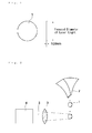
- Figure 1 is a drawing that shows an example of the target used in the laser plasma EUV light source in the first embodiment of the present invention.
- Target 1 is a disc-shaped target of 1 mm diameter and 100 nm thickness made of Sn. The mechanical strength falls if the thickness is under 100 nm, the target is easy to break and it is difficult to handle the target. The thickness may be increased to impart adequate mechanical strength but holding the thickness under 1000 nm is ideal from a viewpoint of debris removal.
- Figure 2 is a drawing that shows the method of providing disc-shaped target 1 in the laser plasma EUV light source in the first embodiment of the present invention.
- Disc-shaped target 1 is sprayed from nozzle 2 that has a slit-shaped aperture and is arranged in the disc direction.
- Disc-shaped target 1 is conveyed on a gas stream. He gas is used in this example.
- Nozzle 2 may be vibrated by a piezo apparatus to spray disc-shaped target 1.
- Target 1 that is sprayed from nozzle 2 reaches the irradiation position of laser light with its direction unchanged since the exterior of nozzle 2 is maintained in a high vacuum.
- pulse laser light 5 of 1.06 ⁇ m wavelength from Nd:YAG light source 4 is focused by lens 3 and irradiated onto target 1.
- the spot diameter of the laser is the same 1 mm diameter as that of target 1.
- the irradiation intensity is adjusted so as to be virtually 1 x 10 11 W/cm 2 . Consequently, the pulse intensity of the light is 80 J/pulse, and the pulse amplitude is 10 ns.
- the irradiation intensity of laser light is 10 2 J/mm 2 /pulse, and the area of a 1 mm diameter disc is 0.785 mm 2 , which results in 78.5 J/pulse.
- the light source operates at 100 Hz repeating frequency with a mean output of 8 kW. EUV output exceeding 16 W (output at the emission point) can be attained with this light source since the Sn target attains conversion efficiency exceeding 2%. EUV output exceeding 160 W would be realized if the excitation light is intensified further with the mean output raised to 80 kW and the repeating frequency raised to 1 kHz.
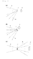
- Figure 3 is a drawing that shows the method of capturing EUV light.
- Figure 3 (a) shows an example in which pulse laser light 5 is irradiated from the normal direction of target 1 and EUV light 6 is captured at the oblique direction relative to the normal line of the disc.
- the convergence spot of pulse laser light 5 with target 1 may adopt an axially-elongated oval shape so that the light source is round when viewed from the capturing direction of EUV light 6.
- Figure 3 (b) shows an example in which pulse laser light 5 is irradiated from the oblique direction relative to the normal line of target 1 and EUV light 6 is captured in the normal direction of target 1.
- the convergence spot of pulse laser light 5 may adopt an axially-elongated oval shape so that the light source is round when viewed from the capturing direction of EUV light 6.
- target 1 would preferably be round.
- Figure 3 (c) shows the method of capturing EUV light 6 from the reverse side of target 1 relative to the irradiation direction of laser light 5.
- An obliquely incident oval mirror or a Schwarzschild optical system are often used in the convergence optical system of EUV light 6, but both are optical systems with central shielding of the pupil, and EUV light near the center of the optical axis cannot be focused.
- beam stop 7 of laser light is arranged in this section to reduce laser light discharged from the EUV light source.
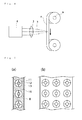
- Figure 4 shows the method of providing disc-shaped targets in a laser plasma EUV light source in the second embodiment of the present invention.
- Tape target 8 in tape form is continuously provided by target drive mechanism 9 in this embodiment.
- Laser light 5 generated by laser light source 4 is focused by lens 3 and irradiated onto tape target 8.
- So-called tape target 8 itself has long been known, but tape target 8 having a different structure from the conventional structure is used in this embodiment.
- Figure 5 (a) shows the structure of such a tape target 8.
- Polyimide resin is used in tape substrate 10.
- Each hole 13 is opened in tape substrate 10 and each disc-shaped target 11 is installed via supporting structures 12 in the center of each hole 13.
- Disc-shaped target 11 is made of Sn and is 100 nm thick.
- the diameter of disc-shaped target 11 is set at 1 mm so as to be virtually equal to the convergent beam diameter of laser light.
- the diameter of hole 13 is sufficiently larger than the convergent beam diameter of laser light and virtually no damage from laser light irradiation reaches tape substrate 10.
- the diameter here is 5 mm.
- the width of tape substrate 10 is 10 mm.
- pulse laser light 5 of 1.06 ⁇ m wavelength from Nd:YAG light source 4 is focused by lens 3 and irradiated onto disc-shaped target 11.
- the spot diameter of the laser is the same 1 mm diameter as that of target 1.
- the irradiation intensity is adjusted so as to be virtually 1 x 10 11 W/cm 2 . Consequently, the pulse intensity of the light is 80 J/pulse, and the pulse amplitude is 10 ns. Therefore, the output is similar to that obtained in the first embodiment.
- a series of disc-shaped targets 11 is arranged in Figure 5 (a), but a plurality of rows may be arranged, as shown in Figure 5 (b), and one tape target may be used a plurality of times.
- FIG. 6 is a drawing that shows one example of the method of producing such tape targets.
- Hole 13 and supporting structure 12 are preformed in polyimide resin tape substrate 10, followed by adhesion of target material 14 of predetermined mass to the center of supporting structure 12. Sn is used in target material 14 here.
- a predetermined mass only of Sn that has been liquified by heating to melt can be dropped in place since Sn is metal with a comparatively low melting point (231.9°C).
- Polyimide resin is not damaged even if molten Sn is adhered since it is resin with a comparatively high glass transition point.
- Sn that had been dropped in the center of supporting structure 12 congeals into a sphere through surface tension and solidifies.
- a tape target provided with disc-shaped target 11 in the center of supporting structure 12 can be constructed in this manner.
- the thickness of disc-shaped target 11 can be adjusted by the pressure in pressing.
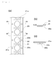
- Figure 7 is a drawing that shows another example of the structure of such a tape target 8.
- Figure 7 (a) is a planar figure, (b) is an A-A cutaway drawing, (c) is a B-B cutaway drawing.
- tape substrate 21 Polyimide resin is used in tape substrate 21.
- Tape substrate 21 has a ladder shape as shown in Figure 7 (a).
- target 22 has a structure in which disc-shaped targets 22a are connected by narrow sections 22b.
- Narrow section 22b is affixed to section 21a corresponding to the rungs of the ladder of tape substrate 21, by means of which target 22 is supported on tape substrate 21.
- Disc-shaped target 22a is positioned in the center of section 21a corresponding to the rungs of the ladder of tape substrate 21 so as to lie in section 21b which is devoid of tape substrate 21. Therefore, even if disc-shaped target 22a is irradiated with laser light, any damage caused by laser light irradiation would not affect tape substrate 21.
- Reference numeral 23 denotes a hole that is opened in tape substrate 21. The timing of laser light irradiation is determined by detecting the position of this hole.
- Figure 8 is a drawing that shows the step of producing the tape targets shown in Figure 7. It shows the section corresponding to A-A profile in Figure 7.
- Film of target 22 material is formed by sputtering on the side without depression 21c of tape substrate 21 upon which is formed section 21c that excludes section 21a corresponding to the rungs (a).
- Material of target 22 is etched in the shape shown in Figure 7. Subsequently, the entire thickness is reduced by etching tape substrate 21 to form hole 21b. in part of depression 21c (c). Finally, hole 23 is formed in the tape substrate (d).
- Figure 9 is a drawing that shows another example of the production of tape target 8.
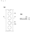
- Figure 9 (a) is a planar figure
- Figure 9 (b) is a cutaway drawing along C-C in Figure 9 (a).
- Polyimide resin is used for tape substrate 24.
- Film of target material 25 is formed on tape substrate 24.
- holes 24a are formed at fixed intervals in tape substrate 24.
- Target material is exposed in part of tape substrate 24 and it plays the role of a plate-shaped target following irradiation by laser light of this section.
- Figure 10 is a drawing that shows the step of producing of the tape targets shown in Figure 9. It shows the portion corresponding to profile C-C in Figure 9.
- Film of target 25 material is formed by sputtering on the side without depression 24b of tape substrate 24 upon which is formed depression 24b at fixed intervals (a). Subsequently, the entire thickness is reduced by etching tape substrate 24 to form hole 24a in part of depression 24b (b).
- Sn metal is used as target material in the embodiment, but the same effects would be realized even if material containing elemental Sn were used.
- materials such as tin oxide (SnO 2 ) may be used, as well as plastic resin in which fine Sn particles are dispersed.
- the EUV exposure apparatus in the embodiment of the present invention has the basic structure of a conventional apparatus shown in Figure 11, with the sole difference lying in the use of the laser plasma EUV light source pursuant to the present invention. Consequently, an explanation of the apparatus is omitted.
Landscapes
- Engineering & Computer Science (AREA)
- Physics & Mathematics (AREA)
- Health & Medical Sciences (AREA)
- Epidemiology (AREA)
- General Physics & Mathematics (AREA)
- Public Health (AREA)
- Atmospheric Sciences (AREA)
- Chemical & Material Sciences (AREA)
- Nanotechnology (AREA)
- Life Sciences & Earth Sciences (AREA)
- Plasma & Fusion (AREA)
- Environmental & Geological Engineering (AREA)
- Crystallography & Structural Chemistry (AREA)
- Optics & Photonics (AREA)
- Theoretical Computer Science (AREA)
- Mathematical Physics (AREA)
- X-Ray Techniques (AREA)
- Exposure And Positioning Against Photoresist Photosensitive Materials (AREA)
- Exposure Of Semiconductors, Excluding Electron Or Ion Beam Exposure (AREA)
Abstract
Description
- The present invention concerns a laser plasma EUV light source, target material ideal for use in an EUV exposure apparatus (also known as an extreme ultraviolet exposure apparatus, and it refers to an exposure apparatus using ultraviolet light of wavelength under 150 nm in the specification and claims), tape material, a method of producing target material, a method of providing targets, and an EUV exposure apparatus.
- In recent years, projection lithographic technology using EUV light having a shorter wavelength (11 to 14 nm) than that of conventional ultraviolet light has been developed to enhance the resolution of optical systems that are limited by the diffraction limit of light accompanying miniaturization of semiconductor integrated circuits. This technology in recent years has been called EUV (Extreme Ultraviolet) lithography. It is expected to be technology capable of providing resolution under 70 nm that had been impossible with conventional optical lithography using a light source of 190 nm wavelength.
- The complex refractive index n of substance in the wavelength range of EUV light is represented by n = 1-δ-ik (i is the complex notation). Imaginary part k in this refractive index represents extreme ultraviolet absorption. Since δ is far smaller than 1, the real part of the refractive index in this range is very close to 1. Furthermore, since k has a finite value in all substances, absorption must take place. Accordingly, an optical system that uses reflection is used since a transparent refractive optical component like a conventional lens cannot be used.
- Figure 11 presents an outline of the EUV exposure apparatus.
EUV light 32 discharged fromEUV light source 31 is incident to illuminationoptical system 33. It forms a virtually parallel luminous flux viaconcave mirror 34 that acts as a collimator mirror. It is then incident tooptical integrator 35 comprising a pair of fly-eye mirrors Japanese Kokai Publication Hei-11-312638 eye mirrors Japanese Kokai Publication Hei-11-312638 - A surface illuminant having a predetermined shape is formed near the reflecting surface of second fly-
eye mirror 35b, specifically, near the emission surface ofoptical integrator 35. Light from the surface illuminant is polarized byplate mirror 36, followed by formation of an elongated, arc shaped illumination region on mask M (a depiction of the perforated plate used to form the arc shaped illumination region is omitted). Light from the pattern on mask M forms an image of the mask pattern on wafer W via projection optical system PL comprising a plurality of mirrors (six mirrors Ml to M6 shown in Figure 11). - The optical system using such mirrors has a ring-shaped projection exposure field in which only aberration at a specific image height is compensated since it cannot compensate for overall aberration in the broad exposure field. The mask and wafer are scanned in synchronization and exposed since a 30 mm square chip cannot be exposed at once in a projection exposure field having such a ring shape.
- A multi-layer film reflecting mirror is generally used as the reflecting mirror in such an EUV exposure apparatus. A multi-layer film is formed on a substrate, and the phase of very weak reflecting light at the interface is aligned and multiply overlapped to obtain high reflectance.
- Reflectance of 67.5% at perpendicular incidence can be attained by using an Mo/Si multi-layer film in which a molybdenum (Mo) layer and a silicon (Si) layer are alternately laminated in the wavelength region near 13.4 nm while reflectance of 70.2% at perpendicular incidence can be attained by using an Mo/Be multi-layer film in which an Mo layer and a beryllium (Be) layer are alternately laminated in the wavelength region near 11.3 nm.
- In light source which is commonly used as EUV
light source 31, laser light is irradiated on target material as excitation light to convert the target material into plasma. The EUV light (exposure light) generated at that time is then used. Such an EUV light source is discussed in the gazette ofJapanese Kokai Publication 2000-56099 - The use of Xe plasma (as both the laser plasma light source and the discharge plasma light source) has been extensively researched and developed as the EUV light source of 13.5 nm wavelength used in an EUV exposure apparatus. The reasons are that a comparatively high conversion efficiency (proportion of EUV light intensity attained relative to input energy) can be attained and that no problems arise associated with debris since the material is gaseous at ambient temperature. However, there are limits to how high a conversion efficiency can be realized because Xe is a gas, and the use of Sn as target material is known to be effective in attaining a higher conversion efficiency.
- There is an electron temperature of ideal plasma for efficient generation of EUV light, and 50 eV is ideal. The electron temperature rises with increase in the irradiation intensity of laser light when the light source is laser plasma. The electron temperature rises excessively and X-rays of short wavelength are generated when the irradiation intensity is too high, thereby lowering the conversion efficiency from laser light to EUV light. Accordingly, there is an ideal laser irradiation intensity, which is about 1011W/cm2.
- The laser spot diameter must be increased to elevate the EUV light output while retaining the ideal light irradiation intensity.
- The size of the EUV light source is limited by the etendue (product of the cross-sectional area of a luminous flux and the solid angle). Etendue is the quantity retained in an optical system. When the product of the size (area) of the light source and the capture solid angle of a convergence optical system exceeds the etendue of a convergence optical system, the excess portion of EUV light cannot be captured in the optical system and is wasted. Consequently, a maximum allowable level of the size of the light source exists.
- Accordingly, setting the light spot diameter to the maximum allowable level would be effective in maximumizing the output of an effective EUV light. For example, if the numerical aperture (NA) of a projection optical system were 0.25 (sin θ = 0.25, or 0.2 sr when converted to a solid angle), the exposure field size were 2 mm x 25 mm, and the δ value of illumination were 0.5, the etendue of this optical system would be 2 x 25 x 0.2 x 0.5 = 5 mm2sr.
- Assuming the capture solid angle of the convergence optical system to be π and the allowable light source size to be 5/π = 1.6 mm2, then the maximum allowable diameter of the light source would be 1.4 mm.
- On the other hand, debris is a serious problem in an EUV light source using plasma. The reflectance falls markedly when debris adheres to the surface of a condenser mirror. Typical debris includes fragments of target material, large particles that solidify after once dissolution, ions generated in plasma, and neutral particles of atomic shape that have lost their charge due to the charge exchange collision of ions, and debris is found in various sizes.
- The so-called limited mass target is an effective method of inhibiting debris comprising fragments of target material and large particles that solidify after once dissolution. This is a method that uses minimum material required for generating plasma. If all target material could be converted into plasma (ionized), the debris that was finely decomposed into atomic shape, including the neutral particles of atomic shape that have lost their charge due to the charge exchange collision of ions as well as ions generated in plasma, could be removed from the optical path by such aspects as a gas curtain, while debris of atomic shape that has a charge could be removed from the optical path by an electromagnetic field.
- Examination of the thickness of target material required to form plasma following irradiation of laser light on a target confirmed a thickness under 100 nm to be adequate. Consequently, the providing of extremely flat target material of 100 nm thickness with a diameter of 1 mm (a value smaller than the 1.4 mm maximum diameter of the allowable light source) that is perpendicular to the incident direction of laser light would be effective in maximizing the EUV output while holding down the amount of debris generation in a laser plasma light source.
- However, nothing that satisfies these requirements has been available in target providing methods considered to date. At present, the jet target method and the droplet target method are the methods of providing targets considered to be effective in inhibiting debris.
- The jet target method is a aspect in which liquid target material is continuously sprayed in a vacuum from a nozzle to continuously provide an elongated columnar target that is solidified instantly due to adiabatic expansion. The droplet target method is a aspect in which target material is continuously sprayed from a nozzle to continuously provide target material that is spherical due to surface tension.
- The target dimensions of these did not differ between the irradiation direction of laser light and the perpendicular direction in either target method, and the extremely flat ideal target shape was not obtained. Accordingly, the entire target could not be converted into plasma and the problems of residue generation due to debris could not be avoided.
- The present invention was devised in view of these circumstances. The objective is to provide a laser plasma EUV light source that can output EUV light of adequate magnitude, target material that can be used in such a laser plasma EUV light source, a method of producing target material, a method of providing targets, and an EUV exposure apparatus that uses such an EUV light source.
- The first aspect for resolving the issues is a laser plasma EUV light source that captures as output the EUV light that is generated through plasma conversion following irradiation of a target with laser light, wherein the target is a plate-shaped target having dimensions that are virtually equal with the convergent beam diameter of the laser light.
- The power of the convergent light is effectively utilized, the conversion efficiency is elevated, and debris generation can be reduced in this aspect since a plate-shaped target having dimensions that are virtually equal with the convergent beam diameter of laser light is used as the target.
- Virtually equal means that the size such that the debris generated poses no problems and it refers to the size in the range of 0.5 to 1.5-times the convergent beam diameter of the laser light. If the target is not round, the size of the circumscribed circle should be within this range. If laser light is incident to the target plane at an angle, the dimensions of the target projected onto a plane perpendicular to the optical axis of the laser light should be within the range.
- The second aspect for resolving the issues is the light source of the first aspect in which the thickness of the plate-shaped target is not more than 1000 nm.
- Virtually the entire target can be converted into plasma with little residue as a result of setting the target thickness at no more than 1000 nm, which thereby reduces the amount of debris generated.
- The third aspect for resolving the issues is the light source of the second aspect in which the thickness of the plate-shaped target is not more than 100 nm.
- Virtually the entire target can be converted into plasma with virtually no residue as a result of setting the target thickness at no more than 100 nm, which further reduces the amount of debris generated.
- The fourth aspect for resolving the issues is the light source of any of the first to third aspects in which the shape of the plate-shaped target is circular viewed from the direction of EUV light output.
- EUV light can be regarded as being generated from a circular light source since the shape of the plate-shaped target is circular when viewed from the direction of EUV light output in this aspect, and it can easily be handled in optical systems subsequently.
- The fifth aspect for resolving the issues is the light source of any of the first to third aspects in which the material of the plate-shaped target is Sn or material containing compounds thereof.
- Sn is ideal material because of its good conversion efficiency of EUV light having short wavelength of approximately 13.5 nm, and while it has a low melting point and is not very hard, it can easily be used to form very thin plate-shaped targets.
- The sixth aspect for resolving the issues is the target used in the laser plasma EUV light source of any of the first to fifth aspects in which the plate-shaped target is held against tape by a support member in a hole of the tape.
- The plate-shaped target can be easily provided and a very thin plate-shaped target can be provided at a stable position since the plate-shaped target is fixed in place against tape by a support member in a hole of the tape.
- The seventh aspect for resolving the issues is tape material in which the plate-shaped material is held against tape by a support member in a hole of the tape.
- This aspect can be used as the sixth aspect.
- The eighth aspect for resolving the issues is the target used in any of the laser plasma EUV light sources of the first to fifth aspects in which the plate-shaped target that is connected by narrow material identical with that of the plate-shaped target is adhered to tape having a ladder shape. The plate-shaped target is located between the rungs of the ladder-shaped tape and the narrow material is located in the rung sections of the ladder-shaped tape.
- The plate-shaped target can be easily provided and a very thin plate-shaped target can be provided at a stable position in this aspect as well.
- The ninth aspect for resolving the issues is the tape material in which plate-shaped material that is connected by narrow material identical with that of the plate-shaped material is adhered to tape having a ladder shape. The plate-shaped material is located between the rungs of the ladder-shaped tape and the narrow material is located in the rung sections of the ladder-shaped tape.
- This aspect can be used as the eighth aspect.
- The tenth aspect for resolving the issues is the target used in any of the laser plasma EUV light sources of the first to fifth aspects in which target material is adhered to tape, wherein holes are opened at fixed intervals in the tape, tape from the opened sections remains removed, and the target material at the sections comprises the plate-shaped target.
- The plate-shaped target can be easily provided and a very thin plate-shaped target can be provided at a stable position in this aspect as well.
- The eleventh aspect for resolving the issues is the tape material to which material is adhered. Holes opened at fixed intervals therein and tape from the opened sections remain removed.
- This aspect can be used as the tenth aspect.
- The twelfth aspect for resolving the issues is the target or tape material of any of the sixth to eleventh aspects in which the tape is polyimide resin.
- Polyimide resin does not suffer damage even if molten Sn should adhere since polymide resin has a comparatively high glass transition point. Therefore, tape rupture and tearing can be prevented.
- The thirteenth aspect for resolving the issues is a method of producing the target of the sixth aspect in which a hole is formed in tape, a support member is formed in the hole so as to be supported by the tape, molten target material is dropped onto the support member and solidified, followed by pressing the solidified target material to a predetermined thickness.
- The target material becomes virtually spherical due to surface tension when molten target material is dropped onto the support member and solidified in this aspect. A very thin disc-shaped target can be completed by pressing. Moreover, the disc-shaped target can be supported by a support member and fixed to the tape.
- The fourteenth aspect for resolving the issues is the method of producing target of the eighth aspect in which tape with depressions established at fixed intervals is prepared and target material that comprises a film is deposited on the side of the tape without depressions, after which the target material that is connected by narrow material identical with that of the plate-shaped target is shaped by etching, followed by reducing the thickness of the tape by etching and opening a hole in the depression of the tape.
- The fifteenth aspect for resolving the issues is a method of producing target of the tenth aspect in which tape with depressions established at fixed intervals is prepared and target material is deposited on the side of the tape without depressions, after which the thickness of the tape is reduced by etching and a hole is opened in the depression of the tape.
- The sixteenth aspect for resolving the issues is the method of providing the target in the laser plasma EUV light source of any of the first to fifth aspects in which individual plate-shaped targets are each conveyed on a carrier gas and sprayed from a nozzle.
- The plate-shaped target can be provided at the convergence point of laser light while in a stable position by this aspect.
- The seventeenth aspect for resolving the issues is the method of providing the target in the laser plasma EUV light source of any of the first to fifth aspects in which a nozzle is vibrated and each of the plate-shaped targets is sprayed from the nozzle by the vibrating force.
- The plate-shaped target can be provided at the convergence point of laser light while in a stable position by this aspect.
- The eighteenth aspect for resolving the issues is the method of providing the target in the laser plasma EUV light source of any of the first to fifth aspects that uses the target of the sixth aspect, eighth aspect, or tenth aspect in which the tape is wound from a tape rewind apparatus about which the tape is wound to a tape winding apparatus that winds the tape, and the plate-shaped target is provided to the convergence point of laser light that is positioned between the rewind apparatus and the winding apparatus by winding the tape.
- The plate-shaped target can be provided at the convergence point of laser light while in a stable position by this aspect.
- The nineteenth aspect for resolving the issues is an EUV exposure apparatus that uses any of the laser plasma EUV light sources of the first to fifth aspects as the light source.
- The throughput of exposure is enhanced in this aspect since high EUV output is obtained and contamination of the optical system by debris is reduced, thereby prolonging the maintenance cycle of the apparatus and reducing the maintenance costs.
-
- Figure 1 is a drawing that shows a disc-shaped target used in the laser plasma EUV light source in one example of the embodiment of the present invention.
- Figure 2 is a drawing that shows the method of providing disc-shaped
target 1 to the laser plasma EUV light source in the first embodiment of the present invention. - Figure 3 is a drawing that shows the method of capturing EUV light.
- Figure 4 is a drawing that shows the method of providing disc-shaped targets in a laser plasma EUV light source in the second embodiment of the present invention.
- Figure 5 is a drawing that shows the tape target used in the laser plasma EUV light source in the second embodiment of the present invention.
- Figure 6 is a drawing that shows one example of the method of producing tape targets shown in Figure 5.
- Figure 7 is a drawing that shows the tape target used in the laser plasma EUV light source in the second embodiment of the present invention.
- Figure 8 is a drawing that shows one example of the method of producing tape targets shown in Figure 7.
- Figure 9 is a drawing that shows the tape target used in the laser plasma EUV light source in the second embodiment of the present invention.
- Figure 10 is a drawing that shows one example of the method of producing tape targets shown in Figure 9.
- Figure 11 is a drawing that shows an outline of the EUV exposure apparatus.
- The embodiment of the present invention is explained below using the drawings. Figure 1 is a drawing that shows an example of the target used in the laser plasma EUV light source in the first embodiment of the present invention.
Target 1 is a disc-shaped target of 1 mm diameter and 100 nm thickness made of Sn. The mechanical strength falls if the thickness is under 100 nm, the target is easy to break and it is difficult to handle the target. The thickness may be increased to impart adequate mechanical strength but holding the thickness under 1000 nm is ideal from a viewpoint of debris removal. - Figure 2 is a drawing that shows the method of providing disc-shaped
target 1 in the laser plasma EUV light source in the first embodiment of the present invention. Disc-shapedtarget 1 is sprayed fromnozzle 2 that has a slit-shaped aperture and is arranged in the disc direction. Disc-shapedtarget 1 is conveyed on a gas stream. He gas is used in this example.Nozzle 2 may be vibrated by a piezo apparatus to spray disc-shapedtarget 1. -
Target 1 that is sprayed fromnozzle 2 reaches the irradiation position of laser light with its direction unchanged since the exterior ofnozzle 2 is maintained in a high vacuum. - Synchronized with delivery of
target 1,pulse laser light 5 of 1.06 µm wavelength from Nd:YAGlight source 4 is focused by lens 3 and irradiated ontotarget 1. The spot diameter of the laser is the same 1 mm diameter as that oftarget 1. The irradiation intensity is adjusted so as to be virtually 1 x 10¹¹W/cm2. Consequently, the pulse intensity of the light is 80 J/pulse, and the pulse amplitude is 10 ns. Specifically, the irradiation intensity of laser light is 102 J/mm2/pulse, and the area of a 1 mm diameter disc is 0.785 mm2, which results in 78.5 J/pulse. - The light source operates at 100 Hz repeating frequency with a mean output of 8 kW. EUV output exceeding 16 W (output at the emission point) can be attained with this light source since the Sn target attains conversion efficiency exceeding 2%. EUV output exceeding 160 W would be realized if the excitation light is intensified further with the mean output raised to 80 kW and the repeating frequency raised to 1 kHz.
- Figure 3 is a drawing that shows the method of capturing EUV light. Figure 3 (a) shows an example in which pulse
laser light 5 is irradiated from the normal direction oftarget 1 andEUV light 6 is captured at the oblique direction relative to the normal line of the disc. In this case, the convergence spot ofpulse laser light 5 withtarget 1 may adopt an axially-elongated oval shape so that the light source is round when viewed from the capturing direction ofEUV light 6. - Figure 3 (b) shows an example in which pulse
laser light 5 is irradiated from the oblique direction relative to the normal line oftarget 1 andEUV light 6 is captured in the normal direction oftarget 1. In this case, the convergence spot ofpulse laser light 5 may adopt an axially-elongated oval shape so that the light source is round when viewed from the capturing direction ofEUV light 6. However,target 1 would preferably be round. - Figure 3 (c) shows the method of capturing EUV light 6 from the reverse side of
target 1 relative to the irradiation direction oflaser light 5. An obliquely incident oval mirror or a Schwarzschild optical system are often used in the convergence optical system ofEUV light 6, but both are optical systems with central shielding of the pupil, and EUV light near the center of the optical axis cannot be focused. Thus,beam stop 7 of laser light is arranged in this section to reduce laser light discharged from the EUV light source. An advantage of this method is that the light source is easily arranged on the EUV exposure apparatus since the optical axis ofpulse laser light 5 is equal to the optical axis ofEUV light 6. - Figure 4 shows the method of providing disc-shaped targets in a laser plasma EUV light source in the second embodiment of the present invention.
Tape target 8 in tape form is continuously provided by target drive mechanism 9 in this embodiment.Laser light 5 generated bylaser light source 4 is focused by lens 3 and irradiated ontotape target 8. So-calledtape target 8 itself has long been known, buttape target 8 having a different structure from the conventional structure is used in this embodiment. - Figure 5 (a) shows the structure of such a
tape target 8. Polyimide resin is used intape substrate 10. Eachhole 13 is opened intape substrate 10 and each disc-shapedtarget 11 is installed via supportingstructures 12 in the center of eachhole 13. - Disc-shaped
target 11 is made of Sn and is 100 nm thick. The diameter of disc-shapedtarget 11 is set at 1 mm so as to be virtually equal to the convergent beam diameter of laser light. The diameter ofhole 13 is sufficiently larger than the convergent beam diameter of laser light and virtually no damage from laser light irradiation reachestape substrate 10. The diameter here is 5 mm. The width oftape substrate 10 is 10 mm. - Virtually no thermal contact is made between disc-shaped
target 11 andtape substrate 10 since supportingstructure 12 is sufficiently thin, and disc-shapedtarget 11 virtually floats in a space. There are four supportingstructures 12 in this drawing, but any number of three or more is permissible. - Synchronized with delivery of
tape target 8 in Figure 4,pulse laser light 5 of 1.06 µm wavelength from Nd:YAGlight source 4 is focused by lens 3 and irradiated onto disc-shapedtarget 11. The spot diameter of the laser is the same 1 mm diameter as that oftarget 1. The irradiation intensity is adjusted so as to be virtually 1 x 10¹¹W/cm2. Consequently, the pulse intensity of the light is 80 J/pulse, and the pulse amplitude is 10 ns. Therefore, the output is similar to that obtained in the first embodiment. - A series of disc-shaped
targets 11 is arranged in Figure 5 (a), but a plurality of rows may be arranged, as shown in Figure 5 (b), and one tape target may be used a plurality of times. - Figure 6 is a drawing that shows one example of the method of producing such tape targets.
Hole 13 and supportingstructure 12 are preformed in polyimideresin tape substrate 10, followed by adhesion oftarget material 14 of predetermined mass to the center of supportingstructure 12. Sn is used intarget material 14 here. - A predetermined mass only of Sn that has been liquified by heating to melt can be dropped in place since Sn is metal with a comparatively low melting point (231.9°C). Polyimide resin is not damaged even if molten Sn is adhered since it is resin with a comparatively high glass transition point. Sn that had been dropped in the center of supporting
structure 12 congeals into a sphere through surface tension and solidifies. - Next, pressure is applied from both sides of tape to complete pressing of
target material 14 adhered to supportingstructure 12. A tape target provided with disc-shapedtarget 11 in the center of supportingstructure 12 can be constructed in this manner. The thickness of disc-shapedtarget 11 can be adjusted by the pressure in pressing. - Figure 7 is a drawing that shows another example of the structure of such a
tape target 8. Figure 7 (a) is a planar figure, (b) is an A-A cutaway drawing, (c) is a B-B cutaway drawing. - Polyimide resin is used in
tape substrate 21.Tape substrate 21 has a ladder shape as shown in Figure 7 (a). On the other hand,target 22 has a structure in which disc-shapedtargets 22a are connected bynarrow sections 22b.Narrow section 22b is affixed tosection 21a corresponding to the rungs of the ladder oftape substrate 21, by means of which target 22 is supported ontape substrate 21. - Disc-shaped
target 22a is positioned in the center ofsection 21a corresponding to the rungs of the ladder oftape substrate 21 so as to lie insection 21b which is devoid oftape substrate 21. Therefore, even if disc-shapedtarget 22a is irradiated with laser light, any damage caused by laser light irradiation would not affecttape substrate 21.Reference numeral 23 denotes a hole that is opened intape substrate 21. The timing of laser light irradiation is determined by detecting the position of this hole. - Figure 8 is a drawing that shows the step of producing the tape targets shown in Figure 7. It shows the section corresponding to A-A profile in Figure 7. Film of
target 22 material is formed by sputtering on the side withoutdepression 21c oftape substrate 21 upon which is formedsection 21c that excludessection 21a corresponding to the rungs (a). Material oftarget 22 is etched in the shape shown in Figure 7. Subsequently, the entire thickness is reduced by etchingtape substrate 21 to form hole 21b. in part ofdepression 21c (c). Finally,hole 23 is formed in the tape substrate (d). - Figure 9 is a drawing that shows another example of the production of
tape target 8. Figure 9 (a) is a planar figure, and Figure 9 (b) is a cutaway drawing along C-C in Figure 9 (a). - Polyimide resin is used for
tape substrate 24. Film oftarget material 25 is formed ontape substrate 24. Furthermore, holes 24a are formed at fixed intervals intape substrate 24. Target material is exposed in part oftape substrate 24 and it plays the role of a plate-shaped target following irradiation by laser light of this section. - Figure 10 is a drawing that shows the step of producing of the tape targets shown in Figure 9. It shows the portion corresponding to profile C-C in Figure 9. Film of
target 25 material is formed by sputtering on the side withoutdepression 24b oftape substrate 24 upon which is formeddepression 24b at fixed intervals (a). Subsequently, the entire thickness is reduced by etchingtape substrate 24 to formhole 24a in part ofdepression 24b (b). - Sn metal is used as target material in the embodiment, but the same effects would be realized even if material containing elemental Sn were used. For example, compounds such as tin oxide (SnO2) may be used, as well as plastic resin in which fine Sn particles are dispersed.
- The EUV exposure apparatus in the embodiment of the present invention has the basic structure of a conventional apparatus shown in Figure 11, with the sole difference lying in the use of the laser plasma EUV light source pursuant to the present invention. Consequently, an explanation of the apparatus is omitted.
Claims (26)
- A laser plasma EUV light source that captures as output the EUV light that is generated through plasma conversion following irradiation of a target with laser light, wherein the target is a plate-shaped target having dimensions that are virtually equal with the convergent beam diameter of the laser light.
- The laser plasma EUV light source of Claim 1 in which the thickness of the plate-shaped target is not more than 1000 nm.
- The laser plasma EUV light source of Claim 2 in which the thickness of the plate-shaped target is not more than 100 nm.
- The laser plasma EUV light source of Claim 1 in which the shape of the plate-shaped target is circular viewed from the direction of EUV light output.
- The laser plasma EUV light source of Claim 1 in which the material of the plate-shaped target is Sn or material containing compounds thereof.
- The target used in the laser plasma EUV light source of Claim 1 in which the plate-shaped target is held against tape by a support member in a hole of the tape.
- The target of Claim 6 in which the tape is polyimide resin.
- Tape material in which plate-shaped material is held against tape by a support member in a hole of the tape.
- The tape material of Claim 8 in which the tape is polyimide resin.
- The target used in the laser plasma EUV light source of Claim 1 in which the plate-shaped target that is connected by narrow material identical with that of the plate-shaped target is adhered to tape having a ladder shape, wherein the plate-shaped target is located between the rungs of the ladder-shaped tape and the narrow material is located in the rung sections of the ladder-shaped tape.
- The target of Claim 10 in which the tape is polyimide resin.
- Tape material in which plate-shaped material that is connected by narrow material identical with that of the plate-shaped material is adhered to tape having a ladder shape, wherein the plate-shaped material is located between the rungs of the ladder-shaped tape and the narrow material is located in the rung sections of the ladder-shaped tape.
- The tape material of Claim 12 in which the tape is polyimide resin.
- The target used in the laser plasma EUV light source of Claim 1 in which target material is adhered to tape, wherein holes are opened at fixed intervals, in the tape, tape from the opened sections remains removed, and the target material at the sections comprises the plate-shaped target.
- The target of Claim 14 in which the tape is polyimide resin.
- Tape material to which material is adhered, wherein holes opened at fixed intervals therein and tape from the opened sections remaining removed.
- The tape material of Claim 16 in which the tape is polyimide resin.
- A method of producing the target of Claim 6 in which a hole is formed in tape, a support member is formed in the hole so as to be supported by the tape, molten target material is dropped onto the support member and solidified, followed by pressing of the solidified target material to a predetermined thickness.
- A method of producing the target of Claim 10 in which tape with depressions established at fixed intervals is prepared and target material is deposited on the side of the tape without depressions, after which the target material that is connected by narrow material identical with that of the plate-shaped target is shaped by etching, followed by reducing the thickness of the tape by etching and opening a hole in the depression of the tape.
- A method of producing the target of Claim 14 in which tape with depressions established at fixed intervals is prepared and target material is deposited on the side of the tape without depressions, after which the thickness of the tape is reduced by etching and a hole is opened in the depression of the tape.
- A method of providing the target in the laser plasma EUV light source of Claim 1 in which individual plate-shaped targets are each conveyed on a carrier gas and sprayed from a nozzle.
- A method of providing the target in the laser plasma EUV light source of Claim 1 in which a nozzle is vibrated and each of the plate-shaped targets is sprayed from the nozzle by the vibrating force.
- A method of providing the target in the laser plasma EUV light source of Claim 1 that uses the target of Claim 6 in which the tape is wound from a tape rewind apparatus about which the tape is wound to a tape winding apparatus that winds the tape, and the plate-shaped target is provided to the convergence point of laser light that is positioned between the rewind apparatus and the winding apparatus by winding the tape.
- A method of providing the target in the laser plasma EUV light source of Claim 1 that uses the target of Claim 10 in which the tape is wound from a tape rewind apparatus about which the tape is wound to a tape winding apparatus that winds the tape, and the plate-shaped target is provided to the convergence point of laser light that is positioned between the rewind apparatus and the winding apparatus by winding the tape.
- A method of providing the target in the laser plasma EUV light source of Claim 1 that uses the target of Claim 14 in which tape is wound from a tape rewind apparatus about which the tape is wound to a tape winding apparatus that winds the tape, and the plate-shaped target is provided to the convergence point of laser light that is positioned between the rewind apparatus and the winding apparatus by winding the tape.
- An EUV exposure apparatus that uses the laser plasma EUV light source of Claim 1 as the light source.
Applications Claiming Priority (2)
| Application Number | Priority Date | Filing Date | Title |
|---|---|---|---|
| JP2005005425 | 2005-01-12 | ||
| PCT/JP2005/024221 WO2006075535A1 (en) | 2005-01-12 | 2005-12-27 | Laser plasma euv light source, target member, production method for target member, target supplying method, and euv exposure system |
Publications (2)
| Publication Number | Publication Date |
|---|---|
| EP1837897A1 true EP1837897A1 (en) | 2007-09-26 |
| EP1837897A4 EP1837897A4 (en) | 2008-04-16 |
Family
ID=36677562
Family Applications (1)
| Application Number | Title | Priority Date | Filing Date |
|---|---|---|---|
| EP05822789A Withdrawn EP1837897A4 (en) | 2005-01-12 | 2005-12-27 | EXTREME PLASMA LASER UV LIGHT SOURCE, TARGET MEMBER, METHOD FOR MANUFACTURING THE TARGET MEMBER, TARGET MEMBER DELIVERY METHOD, AND EXTREME UV EXPOSURE SYSTEM |
Country Status (8)
| Country | Link |
|---|---|
| US (1) | US7456417B2 (en) |
| EP (1) | EP1837897A4 (en) |
| JP (1) | JPWO2006075535A1 (en) |
| KR (1) | KR20070100868A (en) |
| CN (1) | CN101002305A (en) |
| IL (1) | IL182197A0 (en) |
| TW (1) | TW200627544A (en) |
| WO (1) | WO2006075535A1 (en) |
Families Citing this family (26)
| Publication number | Priority date | Publication date | Assignee | Title |
|---|---|---|---|---|
| US7843632B2 (en) * | 2006-08-16 | 2010-11-30 | Cymer, Inc. | EUV optics |
| WO2006075535A1 (en) * | 2005-01-12 | 2006-07-20 | Nikon Corporation | Laser plasma euv light source, target member, production method for target member, target supplying method, and euv exposure system |
| US8525138B2 (en) | 2006-03-31 | 2013-09-03 | Energetiq Technology, Inc. | Laser-driven light source |
| WO2009105546A2 (en) * | 2008-02-19 | 2009-08-27 | Board Of Regents Of The Nevada System Of Higher Education, On Behalf Of The University Of Nevada, Reno | Target and process for fabricating same |
| US8019046B1 (en) * | 2009-04-15 | 2011-09-13 | Eran & Jan, Inc | Apparatus for generating shortwave radiation |
| US9113540B2 (en) * | 2010-02-19 | 2015-08-18 | Gigaphoton Inc. | System and method for generating extreme ultraviolet light |
| US9265136B2 (en) | 2010-02-19 | 2016-02-16 | Gigaphoton Inc. | System and method for generating extreme ultraviolet light |
| US9072153B2 (en) | 2010-03-29 | 2015-06-30 | Gigaphoton Inc. | Extreme ultraviolet light generation system utilizing a pre-pulse to create a diffused dome shaped target |
| JP5802410B2 (en) * | 2010-03-29 | 2015-10-28 | ギガフォトン株式会社 | Extreme ultraviolet light generator |
| US9072152B2 (en) | 2010-03-29 | 2015-06-30 | Gigaphoton Inc. | Extreme ultraviolet light generation system utilizing a variation value formula for the intensity |
| JP5952399B2 (en) * | 2011-08-05 | 2016-07-13 | エーエスエムエル ネザーランズ ビー.ブイ. | Radiation source, method for lithographic apparatus and device manufacturing method |
| US9366967B2 (en) | 2011-09-02 | 2016-06-14 | Asml Netherlands B.V. | Radiation source |
| JP6047573B2 (en) | 2011-09-02 | 2016-12-21 | エーエスエムエル ネザーランズ ビー.ブイ. | Radiation source |
| US9268031B2 (en) * | 2012-04-09 | 2016-02-23 | Kla-Tencor Corporation | Advanced debris mitigation of EUV light source |
| US9357625B2 (en) * | 2014-07-07 | 2016-05-31 | Asml Netherlands B.V. | Extreme ultraviolet light source |
| US20170311429A1 (en) | 2016-04-25 | 2017-10-26 | Asml Netherlands B.V. | Reducing the effect of plasma on an object in an extreme ultraviolet light source |
| US10969690B2 (en) | 2017-09-29 | 2021-04-06 | Taiwan Semiconductor Manufacturing Co., Ltd. | Extreme ultraviolet control system for adjusting droplet illumination parameters |
| US11340531B2 (en) | 2020-07-10 | 2022-05-24 | Taiwan Semiconductor Manufacturing Company, Ltd. | Target control in extreme ultraviolet lithography systems using aberration of reflection image |
| JP7697779B2 (en) * | 2020-10-01 | 2025-06-24 | ギガフォトン株式会社 | Extreme ultraviolet light generation system and method for manufacturing electronic device |
| EP4281824A4 (en) | 2021-01-21 | 2025-01-01 | Hamamatsu Photonics K.K. | Spectrally shaped light source |
| US11587781B2 (en) | 2021-05-24 | 2023-02-21 | Hamamatsu Photonics K.K. | Laser-driven light source with electrodeless ignition |
| US12165856B2 (en) | 2022-02-21 | 2024-12-10 | Hamamatsu Photonics K.K. | Inductively coupled plasma light source |
| US12144072B2 (en) | 2022-03-29 | 2024-11-12 | Hamamatsu Photonics K.K. | All-optical laser-driven light source with electrodeless ignition |
| US12156322B2 (en) | 2022-12-08 | 2024-11-26 | Hamamatsu Photonics K.K. | Inductively coupled plasma light source with switched power supply |
| JP7503159B1 (en) * | 2023-02-03 | 2024-06-19 | レーザーテック株式会社 | Light source |
| US12578076B2 (en) | 2023-06-05 | 2026-03-17 | Hamamatsu Photonics K.K. | Dual-output laser-driven light source |
Family Cites Families (34)
| Publication number | Priority date | Publication date | Assignee | Title |
|---|---|---|---|---|
| JPS62117246A (en) * | 1985-11-15 | 1987-05-28 | Agency Of Ind Science & Technol | Target for high-luminance x-ray generation |
| US4835120A (en) * | 1987-01-12 | 1989-05-30 | Debendra Mallik | Method of making a multilayer molded plastic IC package |
| US4980219A (en) * | 1988-04-06 | 1990-12-25 | Casio Computer Co., Ltd. | Carrier tape for bonding IC devices and method of using the same |
| JPH02100297A (en) * | 1988-10-07 | 1990-04-12 | Mitsubishi Electric Corp | Generation method for x-ray of laser excitation type |
| JPH07167998A (en) * | 1993-12-15 | 1995-07-04 | Nikon Corp | Target for laser plasma X-ray source |
| US5577092A (en) * | 1995-01-25 | 1996-11-19 | Kublak; Glenn D. | Cluster beam targets for laser plasma extreme ultraviolet and soft x-ray sources |
| JPH10221499A (en) | 1997-02-07 | 1998-08-21 | Hitachi Ltd | Laser plasma X-ray source, semiconductor exposure apparatus and semiconductor exposure method using the same |
| JP4238390B2 (en) * | 1998-02-27 | 2009-03-18 | 株式会社ニコン | LIGHTING APPARATUS, EXPOSURE APPARATUS PROVIDED WITH THE ILLUMINATION APPARATUS, AND METHOD FOR MANUFACTURING SEMICONDUCTOR DEVICE USING THE EXPOSURE APPARATUS |
| US6324255B1 (en) * | 1998-08-13 | 2001-11-27 | Nikon Technologies, Inc. | X-ray irradiation apparatus and x-ray exposure apparatus |
| JP2000056099A (en) | 1998-08-13 | 2000-02-25 | Nikon Corp | X-ray irradiation device and X-ray generation position detector |
| US6727980B2 (en) * | 1998-09-17 | 2004-04-27 | Nikon Corporation | Apparatus and method for pattern exposure and method for adjusting the apparatus |
| JP2001023795A (en) * | 1999-07-05 | 2001-01-26 | Toyota Macs Inc | X-ray generator |
| US6831963B2 (en) * | 2000-10-20 | 2004-12-14 | University Of Central Florida | EUV, XUV, and X-Ray wavelength sources created from laser plasma produced from liquid metal solutions |
| FR2801113B1 (en) * | 1999-11-15 | 2003-05-09 | Commissariat Energie Atomique | METHOD OF OBTAINING AND EXTREME ULTRA VIOLET RADIATION SOURCE, LITHOGRAPHIC APPLICATION |
| US6538257B2 (en) * | 1999-12-23 | 2003-03-25 | Koninklijke Philips Electronics N.V. | Method of generating extremely short-wave radiation, and extremely short-wave radiation source unit |
| JP2002214400A (en) * | 2001-01-12 | 2002-07-31 | Toyota Macs Inc | Laser plasma EUV light source device and target used therefor |
| US7405416B2 (en) * | 2005-02-25 | 2008-07-29 | Cymer, Inc. | Method and apparatus for EUV plasma source target delivery |
| US7372056B2 (en) * | 2005-06-29 | 2008-05-13 | Cymer, Inc. | LPP EUV plasma source material target delivery system |
| US7598509B2 (en) * | 2004-11-01 | 2009-10-06 | Cymer, Inc. | Laser produced plasma EUV light source |
| JP3790814B2 (en) * | 2001-10-25 | 2006-06-28 | 独立行政法人産業技術総合研究所 | Method and apparatus for removing scattered matter in X-ray irradiation apparatus |
| US6744851B2 (en) * | 2002-05-31 | 2004-06-01 | Northrop Grumman Corporation | Linear filament array sheet for EUV production |
| AU2003303542A1 (en) * | 2003-01-02 | 2004-07-29 | Jmar Research Inc. | Method and apparatus for generating a membrane target for laser produced plasma |
| DE10306668B4 (en) * | 2003-02-13 | 2009-12-10 | Xtreme Technologies Gmbh | Arrangement for generating intense short-wave radiation based on a plasma |
| JP4052155B2 (en) * | 2003-03-17 | 2008-02-27 | ウシオ電機株式会社 | Extreme ultraviolet radiation source and semiconductor exposure apparatus |
| JP4792705B2 (en) * | 2003-04-03 | 2011-10-12 | 旭硝子株式会社 | Silica glass containing TiO2 and method for producing the same |
| US6973164B2 (en) * | 2003-06-26 | 2005-12-06 | University Of Central Florida Research Foundation, Inc. | Laser-produced plasma EUV light source with pre-pulse enhancement |
| US7087914B2 (en) * | 2004-03-17 | 2006-08-08 | Cymer, Inc | High repetition rate laser produced plasma EUV light source |
| US7164144B2 (en) * | 2004-03-10 | 2007-01-16 | Cymer Inc. | EUV light source |
| US7196342B2 (en) * | 2004-03-10 | 2007-03-27 | Cymer, Inc. | Systems and methods for reducing the influence of plasma-generated debris on the internal components of an EUV light source |
| JP2005276673A (en) * | 2004-03-25 | 2005-10-06 | Komatsu Ltd | LPP type EUV light source device |
| JP4617127B2 (en) * | 2004-09-14 | 2011-01-19 | 財団法人レーザー技術総合研究所 | X-ray generation method and X-ray generator |
| US7355191B2 (en) * | 2004-11-01 | 2008-04-08 | Cymer, Inc. | Systems and methods for cleaning a chamber window of an EUV light source |
| WO2006075535A1 (en) * | 2005-01-12 | 2006-07-20 | Nikon Corporation | Laser plasma euv light source, target member, production method for target member, target supplying method, and euv exposure system |
| JP5156192B2 (en) * | 2006-01-24 | 2013-03-06 | ギガフォトン株式会社 | Extreme ultraviolet light source device |
-
2005
- 2005-12-27 WO PCT/JP2005/024221 patent/WO2006075535A1/en not_active Ceased
- 2005-12-27 KR KR1020077004948A patent/KR20070100868A/en not_active Ceased
- 2005-12-27 CN CNA200580027402XA patent/CN101002305A/en active Pending
- 2005-12-27 EP EP05822789A patent/EP1837897A4/en not_active Withdrawn
- 2005-12-27 JP JP2006552888A patent/JPWO2006075535A1/en active Pending
-
2006
- 2006-01-10 TW TW095100855A patent/TW200627544A/en unknown
- 2006-01-11 US US11/329,116 patent/US7456417B2/en not_active Expired - Lifetime
-
2007
- 2007-03-26 IL IL182197A patent/IL182197A0/en unknown
Also Published As
| Publication number | Publication date |
|---|---|
| WO2006075535A1 (en) | 2006-07-20 |
| EP1837897A4 (en) | 2008-04-16 |
| US7456417B2 (en) | 2008-11-25 |
| JPWO2006075535A1 (en) | 2008-06-12 |
| CN101002305A (en) | 2007-07-18 |
| KR20070100868A (en) | 2007-10-12 |
| TW200627544A (en) | 2006-08-01 |
| US20070007469A1 (en) | 2007-01-11 |
| IL182197A0 (en) | 2007-07-24 |
Similar Documents
| Publication | Publication Date | Title |
|---|---|---|
| US7456417B2 (en) | Laser plasma EUV light source, target material, tape material, a method of producing target material, a method of providing targets, and an EUV exposure device | |
| US11723141B2 (en) | EUV radiation generation methods and systems | |
| US11086224B2 (en) | Fabrication system of semiconductor device and method of fabricating a semiconductor device using the same | |
| US12167525B2 (en) | EUV light source and apparatus for lithography | |
| TWI810289B (en) | Pellicle assembly, method of preparing a pellicle, pellicle for a lithographic apparatus, and use of a pellicle | |
| JP2013251100A (en) | Extreme ultraviolet light generating apparatus and extreme ultraviolet light generating method | |
| JP3919599B2 (en) | Optical element, light source device having the optical element, and exposure apparatus | |
| KR20140060554A (en) | Radiation source | |
| TWI736651B (en) | Lithographic method and apparatus | |
| CN104345570A (en) | Extreme ultraviolet lithography machine light source system and extreme ultraviolet exposure method | |
| CN100485864C (en) | EUV light source, EUV exposure apparatus, and method for manufacturing semiconductor device | |
| HK1105128A (en) | Laser plasma euv light source, target member, production method for target member, target supplying method, and euv exposure system | |
| JP2005191497A (en) | Light source unit, exposure apparatus, and device manufacturing method | |
| US7141806B1 (en) | EUV light source collector erosion mitigation | |
| US11119421B2 (en) | Extreme ultraviolet light condensation mirror, extreme ultraviolet light generation apparatus, and electronic device manufacturing method | |
| JP2005268359A (en) | Mirror and illumination optical device | |
| US12001143B2 (en) | Lithography exposure system with debris removing mechanism | |
| JPH10208998A (en) | Laser plasma X-ray generator and fine pattern transfer method and apparatus using the same | |
| US10859918B2 (en) | Semiconductor apparatus and method of operating the same | |
| US20250021005A1 (en) | System and method for reducing extreme ultraviolet (euv) vessel tin deposition | |
| US20230259020A1 (en) | Euv pellicle with structured ventilation frame | |
| WO2026052392A1 (en) | System and methods for debris reduction | |
| TW202244630A (en) | Pattern formation method | |
| JPS62150749A (en) | Formation of bump electrode | |
| HK1097653A (en) | Euv light source, euv exposure equipment and semiconductor device manufacturing method |
Legal Events
| Date | Code | Title | Description |
|---|---|---|---|
| PUAI | Public reference made under article 153(3) epc to a published international application that has entered the european phase |
Free format text: ORIGINAL CODE: 0009012 |
|
| 17P | Request for examination filed |
Effective date: 20070615 |
|
| AK | Designated contracting states |
Kind code of ref document: A1 Designated state(s): AT BE BG CH CY CZ DE DK EE ES FI FR GB GR HU IE IS IT LI LT LU LV MC NL PL PT RO SE SI SK TR |
|
| REG | Reference to a national code |
Ref country code: HK Ref legal event code: DE Ref document number: 1105128 Country of ref document: HK |
|
| RIC1 | Information provided on ipc code assigned before grant |
Ipc: H05G 2/00 20060101ALI20080306BHEP Ipc: G03F 7/20 20060101AFI20080306BHEP |
|
| A4 | Supplementary search report drawn up and despatched |
Effective date: 20080317 |
|
| DAX | Request for extension of the european patent (deleted) | ||
| 17Q | First examination report despatched |
Effective date: 20080814 |
|
| RAP1 | Party data changed (applicant data changed or rights of an application transferred) |
Owner name: NIKON CORPORATION |
|
| STAA | Information on the status of an ep patent application or granted ep patent |
Free format text: STATUS: THE APPLICATION IS DEEMED TO BE WITHDRAWN |
|
| 18D | Application deemed to be withdrawn |
Effective date: 20120522 |
|
| REG | Reference to a national code |
Ref country code: HK Ref legal event code: WD Ref document number: 1105128 Country of ref document: HK |