EP1837831A2 - Case for portable device - Google Patents
Case for portable device Download PDFInfo
- Publication number
- EP1837831A2 EP1837831A2 EP07104572A EP07104572A EP1837831A2 EP 1837831 A2 EP1837831 A2 EP 1837831A2 EP 07104572 A EP07104572 A EP 07104572A EP 07104572 A EP07104572 A EP 07104572A EP 1837831 A2 EP1837831 A2 EP 1837831A2
- Authority
- EP
- European Patent Office
- Prior art keywords
- case part
- case
- transparent portion
- transparent
- portable device
- Prior art date
- Legal status (The legal status is an assumption and is not a legal conclusion. Google has not performed a legal analysis and makes no representation as to the accuracy of the status listed.)
- Withdrawn
Links
Images


Classifications
-
- G—PHYSICS
- G07—CHECKING-DEVICES
- G07C—TIME OR ATTENDANCE REGISTERS; REGISTERING OR INDICATING THE WORKING OF MACHINES; GENERATING RANDOM NUMBERS; VOTING OR LOTTERY APPARATUS; ARRANGEMENTS, SYSTEMS OR APPARATUS FOR CHECKING NOT PROVIDED FOR ELSEWHERE
- G07C9/00—Individual registration on entry or exit
- G07C9/00174—Electronically operated locks; Circuits therefor; Nonmechanical keys therefor, e.g. passive or active electrical keys or other data carriers without mechanical keys
- G07C9/00944—Details of construction or manufacture
-
- B—PERFORMING OPERATIONS; TRANSPORTING
- B29—WORKING OF PLASTICS; WORKING OF SUBSTANCES IN A PLASTIC STATE IN GENERAL
- B29C—SHAPING OR JOINING OF PLASTICS; SHAPING OF MATERIAL IN A PLASTIC STATE, NOT OTHERWISE PROVIDED FOR; AFTER-TREATMENT OF THE SHAPED PRODUCTS, e.g. REPAIRING
- B29C65/00—Joining or sealing of preformed parts, e.g. welding of plastics materials; Apparatus therefor
- B29C65/02—Joining or sealing of preformed parts, e.g. welding of plastics materials; Apparatus therefor by heating, with or without pressure
- B29C65/14—Joining or sealing of preformed parts, e.g. welding of plastics materials; Apparatus therefor by heating, with or without pressure using wave energy, i.e. electromagnetic radiation, or particle radiation
- B29C65/16—Laser beams
- B29C65/1629—Laser beams characterised by the way of heating the interface
- B29C65/1635—Laser beams characterised by the way of heating the interface at least passing through one of the parts to be joined, i.e. laser transmission welding
-
- B—PERFORMING OPERATIONS; TRANSPORTING
- B29—WORKING OF PLASTICS; WORKING OF SUBSTANCES IN A PLASTIC STATE IN GENERAL
- B29C—SHAPING OR JOINING OF PLASTICS; SHAPING OF MATERIAL IN A PLASTIC STATE, NOT OTHERWISE PROVIDED FOR; AFTER-TREATMENT OF THE SHAPED PRODUCTS, e.g. REPAIRING
- B29C65/00—Joining or sealing of preformed parts, e.g. welding of plastics materials; Apparatus therefor
- B29C65/02—Joining or sealing of preformed parts, e.g. welding of plastics materials; Apparatus therefor by heating, with or without pressure
- B29C65/14—Joining or sealing of preformed parts, e.g. welding of plastics materials; Apparatus therefor by heating, with or without pressure using wave energy, i.e. electromagnetic radiation, or particle radiation
- B29C65/16—Laser beams
- B29C65/1629—Laser beams characterised by the way of heating the interface
- B29C65/1654—Laser beams characterised by the way of heating the interface scanning at least one of the parts to be joined
-
- B—PERFORMING OPERATIONS; TRANSPORTING
- B29—WORKING OF PLASTICS; WORKING OF SUBSTANCES IN A PLASTIC STATE IN GENERAL
- B29C—SHAPING OR JOINING OF PLASTICS; SHAPING OF MATERIAL IN A PLASTIC STATE, NOT OTHERWISE PROVIDED FOR; AFTER-TREATMENT OF THE SHAPED PRODUCTS, e.g. REPAIRING
- B29C66/00—General aspects of processes or apparatus for joining preformed parts
- B29C66/01—General aspects dealing with the joint area or with the area to be joined
- B29C66/342—Preventing air-inclusions
-
- B—PERFORMING OPERATIONS; TRANSPORTING
- B29—WORKING OF PLASTICS; WORKING OF SUBSTANCES IN A PLASTIC STATE IN GENERAL
- B29C—SHAPING OR JOINING OF PLASTICS; SHAPING OF MATERIAL IN A PLASTIC STATE, NOT OTHERWISE PROVIDED FOR; AFTER-TREATMENT OF THE SHAPED PRODUCTS, e.g. REPAIRING
- B29C66/00—General aspects of processes or apparatus for joining preformed parts
- B29C66/50—General aspects of joining tubular articles; General aspects of joining long products, i.e. bars or profiled elements; General aspects of joining single elements to tubular articles, hollow articles or bars; General aspects of joining several hollow-preforms to form hollow or tubular articles
- B29C66/51—Joining tubular articles, profiled elements or bars; Joining single elements to tubular articles, hollow articles or bars; Joining several hollow-preforms to form hollow or tubular articles
- B29C66/54—Joining several hollow-preforms, e.g. half-shells, to form hollow articles, e.g. for making balls, containers; Joining several hollow-preforms, e.g. half-cylinders, to form tubular articles
-
- B—PERFORMING OPERATIONS; TRANSPORTING
- B29—WORKING OF PLASTICS; WORKING OF SUBSTANCES IN A PLASTIC STATE IN GENERAL
- B29C—SHAPING OR JOINING OF PLASTICS; SHAPING OF MATERIAL IN A PLASTIC STATE, NOT OTHERWISE PROVIDED FOR; AFTER-TREATMENT OF THE SHAPED PRODUCTS, e.g. REPAIRING
- B29C66/00—General aspects of processes or apparatus for joining preformed parts
- B29C66/50—General aspects of joining tubular articles; General aspects of joining long products, i.e. bars or profiled elements; General aspects of joining single elements to tubular articles, hollow articles or bars; General aspects of joining several hollow-preforms to form hollow or tubular articles
- B29C66/51—Joining tubular articles, profiled elements or bars; Joining single elements to tubular articles, hollow articles or bars; Joining several hollow-preforms to form hollow or tubular articles
- B29C66/54—Joining several hollow-preforms, e.g. half-shells, to form hollow articles, e.g. for making balls, containers; Joining several hollow-preforms, e.g. half-cylinders, to form tubular articles
- B29C66/542—Joining several hollow-preforms, e.g. half-shells, to form hollow articles, e.g. for making balls, containers; Joining several hollow-preforms, e.g. half-cylinders, to form tubular articles joining hollow covers or hollow bottoms to open ends of container bodies
-
- B—PERFORMING OPERATIONS; TRANSPORTING
- B29—WORKING OF PLASTICS; WORKING OF SUBSTANCES IN A PLASTIC STATE IN GENERAL
- B29C—SHAPING OR JOINING OF PLASTICS; SHAPING OF MATERIAL IN A PLASTIC STATE, NOT OTHERWISE PROVIDED FOR; AFTER-TREATMENT OF THE SHAPED PRODUCTS, e.g. REPAIRING
- B29C66/00—General aspects of processes or apparatus for joining preformed parts
- B29C66/50—General aspects of joining tubular articles; General aspects of joining long products, i.e. bars or profiled elements; General aspects of joining single elements to tubular articles, hollow articles or bars; General aspects of joining several hollow-preforms to form hollow or tubular articles
- B29C66/51—Joining tubular articles, profiled elements or bars; Joining single elements to tubular articles, hollow articles or bars; Joining several hollow-preforms to form hollow or tubular articles
- B29C66/54—Joining several hollow-preforms, e.g. half-shells, to form hollow articles, e.g. for making balls, containers; Joining several hollow-preforms, e.g. half-cylinders, to form tubular articles
- B29C66/543—Joining several hollow-preforms, e.g. half-shells, to form hollow articles, e.g. for making balls, containers; Joining several hollow-preforms, e.g. half-cylinders, to form tubular articles joining more than two hollow-preforms to form said hollow articles
-
- B—PERFORMING OPERATIONS; TRANSPORTING
- B29—WORKING OF PLASTICS; WORKING OF SUBSTANCES IN A PLASTIC STATE IN GENERAL
- B29C—SHAPING OR JOINING OF PLASTICS; SHAPING OF MATERIAL IN A PLASTIC STATE, NOT OTHERWISE PROVIDED FOR; AFTER-TREATMENT OF THE SHAPED PRODUCTS, e.g. REPAIRING
- B29C66/00—General aspects of processes or apparatus for joining preformed parts
- B29C66/50—General aspects of joining tubular articles; General aspects of joining long products, i.e. bars or profiled elements; General aspects of joining single elements to tubular articles, hollow articles or bars; General aspects of joining several hollow-preforms to form hollow or tubular articles
- B29C66/65—General aspects of joining tubular articles; General aspects of joining long products, i.e. bars or profiled elements; General aspects of joining single elements to tubular articles, hollow articles or bars; General aspects of joining several hollow-preforms to form hollow or tubular articles with a relative motion between the article and the welding tool
-
- B—PERFORMING OPERATIONS; TRANSPORTING
- B29—WORKING OF PLASTICS; WORKING OF SUBSTANCES IN A PLASTIC STATE IN GENERAL
- B29C—SHAPING OR JOINING OF PLASTICS; SHAPING OF MATERIAL IN A PLASTIC STATE, NOT OTHERWISE PROVIDED FOR; AFTER-TREATMENT OF THE SHAPED PRODUCTS, e.g. REPAIRING
- B29C66/00—General aspects of processes or apparatus for joining preformed parts
- B29C66/50—General aspects of joining tubular articles; General aspects of joining long products, i.e. bars or profiled elements; General aspects of joining single elements to tubular articles, hollow articles or bars; General aspects of joining several hollow-preforms to form hollow or tubular articles
- B29C66/65—General aspects of joining tubular articles; General aspects of joining long products, i.e. bars or profiled elements; General aspects of joining single elements to tubular articles, hollow articles or bars; General aspects of joining several hollow-preforms to form hollow or tubular articles with a relative motion between the article and the welding tool
- B29C66/652—General aspects of joining tubular articles; General aspects of joining long products, i.e. bars or profiled elements; General aspects of joining single elements to tubular articles, hollow articles or bars; General aspects of joining several hollow-preforms to form hollow or tubular articles with a relative motion between the article and the welding tool moving the welding tool around the fixed article
-
- B—PERFORMING OPERATIONS; TRANSPORTING
- B29—WORKING OF PLASTICS; WORKING OF SUBSTANCES IN A PLASTIC STATE IN GENERAL
- B29C—SHAPING OR JOINING OF PLASTICS; SHAPING OF MATERIAL IN A PLASTIC STATE, NOT OTHERWISE PROVIDED FOR; AFTER-TREATMENT OF THE SHAPED PRODUCTS, e.g. REPAIRING
- B29C66/00—General aspects of processes or apparatus for joining preformed parts
- B29C66/70—General aspects of processes or apparatus for joining preformed parts characterised by the composition, physical properties or the structure of the material of the parts to be joined; Joining with non-plastics material
- B29C66/73—General aspects of processes or apparatus for joining preformed parts characterised by the composition, physical properties or the structure of the material of the parts to be joined; Joining with non-plastics material characterised by the intensive physical properties of the material of the parts to be joined, by the optical properties of the material of the parts to be joined, by the extensive physical properties of the parts to be joined, by the state of the material of the parts to be joined or by the material of the parts to be joined being a thermoplastic or a thermoset
- B29C66/733—General aspects of processes or apparatus for joining preformed parts characterised by the composition, physical properties or the structure of the material of the parts to be joined; Joining with non-plastics material characterised by the intensive physical properties of the material of the parts to be joined, by the optical properties of the material of the parts to be joined, by the extensive physical properties of the parts to be joined, by the state of the material of the parts to be joined or by the material of the parts to be joined being a thermoplastic or a thermoset characterised by the optical properties of the material of the parts to be joined, e.g. fluorescence, phosphorescence
- B29C66/7336—General aspects of processes or apparatus for joining preformed parts characterised by the composition, physical properties or the structure of the material of the parts to be joined; Joining with non-plastics material characterised by the intensive physical properties of the material of the parts to be joined, by the optical properties of the material of the parts to be joined, by the extensive physical properties of the parts to be joined, by the state of the material of the parts to be joined or by the material of the parts to be joined being a thermoplastic or a thermoset characterised by the optical properties of the material of the parts to be joined, e.g. fluorescence, phosphorescence at least one of the parts to be joined being opaque, transparent or translucent to visible light
- B29C66/73365—General aspects of processes or apparatus for joining preformed parts characterised by the composition, physical properties or the structure of the material of the parts to be joined; Joining with non-plastics material characterised by the intensive physical properties of the material of the parts to be joined, by the optical properties of the material of the parts to be joined, by the extensive physical properties of the parts to be joined, by the state of the material of the parts to be joined or by the material of the parts to be joined being a thermoplastic or a thermoset characterised by the optical properties of the material of the parts to be joined, e.g. fluorescence, phosphorescence at least one of the parts to be joined being opaque, transparent or translucent to visible light at least one of the parts to be joined being transparent or translucent to visible light
-
- B—PERFORMING OPERATIONS; TRANSPORTING
- B29—WORKING OF PLASTICS; WORKING OF SUBSTANCES IN A PLASTIC STATE IN GENERAL
- B29C—SHAPING OR JOINING OF PLASTICS; SHAPING OF MATERIAL IN A PLASTIC STATE, NOT OTHERWISE PROVIDED FOR; AFTER-TREATMENT OF THE SHAPED PRODUCTS, e.g. REPAIRING
- B29C66/00—General aspects of processes or apparatus for joining preformed parts
- B29C66/80—General aspects of machine operations or constructions and parts thereof
- B29C66/83—General aspects of machine operations or constructions and parts thereof characterised by the movement of the joining or pressing tools
- B29C66/836—Moving relative to and tangentially to the parts to be joined, e.g. transversely to the displacement of the parts to be joined, e.g. using a X-Y table
-
- B—PERFORMING OPERATIONS; TRANSPORTING
- B29—WORKING OF PLASTICS; WORKING OF SUBSTANCES IN A PLASTIC STATE IN GENERAL
- B29C—SHAPING OR JOINING OF PLASTICS; SHAPING OF MATERIAL IN A PLASTIC STATE, NOT OTHERWISE PROVIDED FOR; AFTER-TREATMENT OF THE SHAPED PRODUCTS, e.g. REPAIRING
- B29C65/00—Joining or sealing of preformed parts, e.g. welding of plastics materials; Apparatus therefor
- B29C65/02—Joining or sealing of preformed parts, e.g. welding of plastics materials; Apparatus therefor by heating, with or without pressure
- B29C65/06—Joining or sealing of preformed parts, e.g. welding of plastics materials; Apparatus therefor by heating, with or without pressure using friction, e.g. spin welding
-
- B—PERFORMING OPERATIONS; TRANSPORTING
- B29—WORKING OF PLASTICS; WORKING OF SUBSTANCES IN A PLASTIC STATE IN GENERAL
- B29C—SHAPING OR JOINING OF PLASTICS; SHAPING OF MATERIAL IN A PLASTIC STATE, NOT OTHERWISE PROVIDED FOR; AFTER-TREATMENT OF THE SHAPED PRODUCTS, e.g. REPAIRING
- B29C65/00—Joining or sealing of preformed parts, e.g. welding of plastics materials; Apparatus therefor
- B29C65/02—Joining or sealing of preformed parts, e.g. welding of plastics materials; Apparatus therefor by heating, with or without pressure
- B29C65/08—Joining or sealing of preformed parts, e.g. welding of plastics materials; Apparatus therefor by heating, with or without pressure using ultrasonic vibrations
-
- B—PERFORMING OPERATIONS; TRANSPORTING
- B29—WORKING OF PLASTICS; WORKING OF SUBSTANCES IN A PLASTIC STATE IN GENERAL
- B29C—SHAPING OR JOINING OF PLASTICS; SHAPING OF MATERIAL IN A PLASTIC STATE, NOT OTHERWISE PROVIDED FOR; AFTER-TREATMENT OF THE SHAPED PRODUCTS, e.g. REPAIRING
- B29C65/00—Joining or sealing of preformed parts, e.g. welding of plastics materials; Apparatus therefor
- B29C65/02—Joining or sealing of preformed parts, e.g. welding of plastics materials; Apparatus therefor by heating, with or without pressure
- B29C65/14—Joining or sealing of preformed parts, e.g. welding of plastics materials; Apparatus therefor by heating, with or without pressure using wave energy, i.e. electromagnetic radiation, or particle radiation
- B29C65/16—Laser beams
- B29C65/1677—Laser beams making use of an absorber or impact modifier
-
- B—PERFORMING OPERATIONS; TRANSPORTING
- B29—WORKING OF PLASTICS; WORKING OF SUBSTANCES IN A PLASTIC STATE IN GENERAL
- B29C—SHAPING OR JOINING OF PLASTICS; SHAPING OF MATERIAL IN A PLASTIC STATE, NOT OTHERWISE PROVIDED FOR; AFTER-TREATMENT OF THE SHAPED PRODUCTS, e.g. REPAIRING
- B29C65/00—Joining or sealing of preformed parts, e.g. welding of plastics materials; Apparatus therefor
- B29C65/02—Joining or sealing of preformed parts, e.g. welding of plastics materials; Apparatus therefor by heating, with or without pressure
- B29C65/14—Joining or sealing of preformed parts, e.g. welding of plastics materials; Apparatus therefor by heating, with or without pressure using wave energy, i.e. electromagnetic radiation, or particle radiation
- B29C65/16—Laser beams
- B29C65/1687—Laser beams making use of light guides
-
- B—PERFORMING OPERATIONS; TRANSPORTING
- B29—WORKING OF PLASTICS; WORKING OF SUBSTANCES IN A PLASTIC STATE IN GENERAL
- B29C—SHAPING OR JOINING OF PLASTICS; SHAPING OF MATERIAL IN A PLASTIC STATE, NOT OTHERWISE PROVIDED FOR; AFTER-TREATMENT OF THE SHAPED PRODUCTS, e.g. REPAIRING
- B29C65/00—Joining or sealing of preformed parts, e.g. welding of plastics materials; Apparatus therefor
- B29C65/02—Joining or sealing of preformed parts, e.g. welding of plastics materials; Apparatus therefor by heating, with or without pressure
- B29C65/14—Joining or sealing of preformed parts, e.g. welding of plastics materials; Apparatus therefor by heating, with or without pressure using wave energy, i.e. electromagnetic radiation, or particle radiation
- B29C65/16—Laser beams
- B29C65/1696—Laser beams making use of masks
-
- B—PERFORMING OPERATIONS; TRANSPORTING
- B29—WORKING OF PLASTICS; WORKING OF SUBSTANCES IN A PLASTIC STATE IN GENERAL
- B29C—SHAPING OR JOINING OF PLASTICS; SHAPING OF MATERIAL IN A PLASTIC STATE, NOT OTHERWISE PROVIDED FOR; AFTER-TREATMENT OF THE SHAPED PRODUCTS, e.g. REPAIRING
- B29C65/00—Joining or sealing of preformed parts, e.g. welding of plastics materials; Apparatus therefor
- B29C65/02—Joining or sealing of preformed parts, e.g. welding of plastics materials; Apparatus therefor by heating, with or without pressure
- B29C65/18—Joining or sealing of preformed parts, e.g. welding of plastics materials; Apparatus therefor by heating, with or without pressure using heated tools
- B29C65/20—Joining or sealing of preformed parts, e.g. welding of plastics materials; Apparatus therefor by heating, with or without pressure using heated tools with direct contact, e.g. using "mirror"
-
- B—PERFORMING OPERATIONS; TRANSPORTING
- B29—WORKING OF PLASTICS; WORKING OF SUBSTANCES IN A PLASTIC STATE IN GENERAL
- B29C—SHAPING OR JOINING OF PLASTICS; SHAPING OF MATERIAL IN A PLASTIC STATE, NOT OTHERWISE PROVIDED FOR; AFTER-TREATMENT OF THE SHAPED PRODUCTS, e.g. REPAIRING
- B29C65/00—Joining or sealing of preformed parts, e.g. welding of plastics materials; Apparatus therefor
- B29C65/82—Testing the joint
- B29C65/8253—Testing the joint by the use of waves or particle radiation, e.g. visual examination, scanning electron microscopy, or X-rays
-
- B—PERFORMING OPERATIONS; TRANSPORTING
- B29—WORKING OF PLASTICS; WORKING OF SUBSTANCES IN A PLASTIC STATE IN GENERAL
- B29C—SHAPING OR JOINING OF PLASTICS; SHAPING OF MATERIAL IN A PLASTIC STATE, NOT OTHERWISE PROVIDED FOR; AFTER-TREATMENT OF THE SHAPED PRODUCTS, e.g. REPAIRING
- B29C66/00—General aspects of processes or apparatus for joining preformed parts
- B29C66/01—General aspects dealing with the joint area or with the area to be joined
- B29C66/03—After-treatments in the joint area
- B29C66/032—Mechanical after-treatments
- B29C66/0322—Post-pressing without reshaping, i.e. keeping the joint under pressure after joining
-
- B—PERFORMING OPERATIONS; TRANSPORTING
- B29—WORKING OF PLASTICS; WORKING OF SUBSTANCES IN A PLASTIC STATE IN GENERAL
- B29C—SHAPING OR JOINING OF PLASTICS; SHAPING OF MATERIAL IN A PLASTIC STATE, NOT OTHERWISE PROVIDED FOR; AFTER-TREATMENT OF THE SHAPED PRODUCTS, e.g. REPAIRING
- B29C66/00—General aspects of processes or apparatus for joining preformed parts
- B29C66/01—General aspects dealing with the joint area or with the area to be joined
- B29C66/05—Particular design of joint configurations
- B29C66/20—Particular design of joint configurations particular design of the joint lines, e.g. of the weld lines
- B29C66/21—Particular design of joint configurations particular design of the joint lines, e.g. of the weld lines said joint lines being formed by a single dot or dash or by several dots or dashes, i.e. spot joining or spot welding
-
- B—PERFORMING OPERATIONS; TRANSPORTING
- B29—WORKING OF PLASTICS; WORKING OF SUBSTANCES IN A PLASTIC STATE IN GENERAL
- B29C—SHAPING OR JOINING OF PLASTICS; SHAPING OF MATERIAL IN A PLASTIC STATE, NOT OTHERWISE PROVIDED FOR; AFTER-TREATMENT OF THE SHAPED PRODUCTS, e.g. REPAIRING
- B29C66/00—General aspects of processes or apparatus for joining preformed parts
- B29C66/70—General aspects of processes or apparatus for joining preformed parts characterised by the composition, physical properties or the structure of the material of the parts to be joined; Joining with non-plastics material
- B29C66/71—General aspects of processes or apparatus for joining preformed parts characterised by the composition, physical properties or the structure of the material of the parts to be joined; Joining with non-plastics material characterised by the composition of the plastics material of the parts to be joined
-
- B—PERFORMING OPERATIONS; TRANSPORTING
- B29—WORKING OF PLASTICS; WORKING OF SUBSTANCES IN A PLASTIC STATE IN GENERAL
- B29C—SHAPING OR JOINING OF PLASTICS; SHAPING OF MATERIAL IN A PLASTIC STATE, NOT OTHERWISE PROVIDED FOR; AFTER-TREATMENT OF THE SHAPED PRODUCTS, e.g. REPAIRING
- B29C66/00—General aspects of processes or apparatus for joining preformed parts
- B29C66/70—General aspects of processes or apparatus for joining preformed parts characterised by the composition, physical properties or the structure of the material of the parts to be joined; Joining with non-plastics material
- B29C66/73—General aspects of processes or apparatus for joining preformed parts characterised by the composition, physical properties or the structure of the material of the parts to be joined; Joining with non-plastics material characterised by the intensive physical properties of the material of the parts to be joined, by the optical properties of the material of the parts to be joined, by the extensive physical properties of the parts to be joined, by the state of the material of the parts to be joined or by the material of the parts to be joined being a thermoplastic or a thermoset
- B29C66/737—General aspects of processes or apparatus for joining preformed parts characterised by the composition, physical properties or the structure of the material of the parts to be joined; Joining with non-plastics material characterised by the intensive physical properties of the material of the parts to be joined, by the optical properties of the material of the parts to be joined, by the extensive physical properties of the parts to be joined, by the state of the material of the parts to be joined or by the material of the parts to be joined being a thermoplastic or a thermoset characterised by the state of the material of the parts to be joined
- B29C66/7377—General aspects of processes or apparatus for joining preformed parts characterised by the composition, physical properties or the structure of the material of the parts to be joined; Joining with non-plastics material characterised by the intensive physical properties of the material of the parts to be joined, by the optical properties of the material of the parts to be joined, by the extensive physical properties of the parts to be joined, by the state of the material of the parts to be joined or by the material of the parts to be joined being a thermoplastic or a thermoset characterised by the state of the material of the parts to be joined amorphous, semi-crystalline or crystalline
- B29C66/73771—General aspects of processes or apparatus for joining preformed parts characterised by the composition, physical properties or the structure of the material of the parts to be joined; Joining with non-plastics material characterised by the intensive physical properties of the material of the parts to be joined, by the optical properties of the material of the parts to be joined, by the extensive physical properties of the parts to be joined, by the state of the material of the parts to be joined or by the material of the parts to be joined being a thermoplastic or a thermoset characterised by the state of the material of the parts to be joined amorphous, semi-crystalline or crystalline the to-be-joined area of at least one of the parts to be joined being amorphous
- B29C66/73772—General aspects of processes or apparatus for joining preformed parts characterised by the composition, physical properties or the structure of the material of the parts to be joined; Joining with non-plastics material characterised by the intensive physical properties of the material of the parts to be joined, by the optical properties of the material of the parts to be joined, by the extensive physical properties of the parts to be joined, by the state of the material of the parts to be joined or by the material of the parts to be joined being a thermoplastic or a thermoset characterised by the state of the material of the parts to be joined amorphous, semi-crystalline or crystalline the to-be-joined area of at least one of the parts to be joined being amorphous the to-be-joined areas of both parts to be joined being amorphous
-
- B—PERFORMING OPERATIONS; TRANSPORTING
- B29—WORKING OF PLASTICS; WORKING OF SUBSTANCES IN A PLASTIC STATE IN GENERAL
- B29C—SHAPING OR JOINING OF PLASTICS; SHAPING OF MATERIAL IN A PLASTIC STATE, NOT OTHERWISE PROVIDED FOR; AFTER-TREATMENT OF THE SHAPED PRODUCTS, e.g. REPAIRING
- B29C66/00—General aspects of processes or apparatus for joining preformed parts
- B29C66/70—General aspects of processes or apparatus for joining preformed parts characterised by the composition, physical properties or the structure of the material of the parts to be joined; Joining with non-plastics material
- B29C66/73—General aspects of processes or apparatus for joining preformed parts characterised by the composition, physical properties or the structure of the material of the parts to be joined; Joining with non-plastics material characterised by the intensive physical properties of the material of the parts to be joined, by the optical properties of the material of the parts to be joined, by the extensive physical properties of the parts to be joined, by the state of the material of the parts to be joined or by the material of the parts to be joined being a thermoplastic or a thermoset
- B29C66/737—General aspects of processes or apparatus for joining preformed parts characterised by the composition, physical properties or the structure of the material of the parts to be joined; Joining with non-plastics material characterised by the intensive physical properties of the material of the parts to be joined, by the optical properties of the material of the parts to be joined, by the extensive physical properties of the parts to be joined, by the state of the material of the parts to be joined or by the material of the parts to be joined being a thermoplastic or a thermoset characterised by the state of the material of the parts to be joined
- B29C66/7377—General aspects of processes or apparatus for joining preformed parts characterised by the composition, physical properties or the structure of the material of the parts to be joined; Joining with non-plastics material characterised by the intensive physical properties of the material of the parts to be joined, by the optical properties of the material of the parts to be joined, by the extensive physical properties of the parts to be joined, by the state of the material of the parts to be joined or by the material of the parts to be joined being a thermoplastic or a thermoset characterised by the state of the material of the parts to be joined amorphous, semi-crystalline or crystalline
- B29C66/73775—General aspects of processes or apparatus for joining preformed parts characterised by the composition, physical properties or the structure of the material of the parts to be joined; Joining with non-plastics material characterised by the intensive physical properties of the material of the parts to be joined, by the optical properties of the material of the parts to be joined, by the extensive physical properties of the parts to be joined, by the state of the material of the parts to be joined or by the material of the parts to be joined being a thermoplastic or a thermoset characterised by the state of the material of the parts to be joined amorphous, semi-crystalline or crystalline the to-be-joined area of at least one of the parts to be joined being crystalline
- B29C66/73776—General aspects of processes or apparatus for joining preformed parts characterised by the composition, physical properties or the structure of the material of the parts to be joined; Joining with non-plastics material characterised by the intensive physical properties of the material of the parts to be joined, by the optical properties of the material of the parts to be joined, by the extensive physical properties of the parts to be joined, by the state of the material of the parts to be joined or by the material of the parts to be joined being a thermoplastic or a thermoset characterised by the state of the material of the parts to be joined amorphous, semi-crystalline or crystalline the to-be-joined area of at least one of the parts to be joined being crystalline the to-be-joined areas of both parts to be joined being crystalline
-
- B—PERFORMING OPERATIONS; TRANSPORTING
- B29—WORKING OF PLASTICS; WORKING OF SUBSTANCES IN A PLASTIC STATE IN GENERAL
- B29C—SHAPING OR JOINING OF PLASTICS; SHAPING OF MATERIAL IN A PLASTIC STATE, NOT OTHERWISE PROVIDED FOR; AFTER-TREATMENT OF THE SHAPED PRODUCTS, e.g. REPAIRING
- B29C66/00—General aspects of processes or apparatus for joining preformed parts
- B29C66/70—General aspects of processes or apparatus for joining preformed parts characterised by the composition, physical properties or the structure of the material of the parts to be joined; Joining with non-plastics material
- B29C66/73—General aspects of processes or apparatus for joining preformed parts characterised by the composition, physical properties or the structure of the material of the parts to be joined; Joining with non-plastics material characterised by the intensive physical properties of the material of the parts to be joined, by the optical properties of the material of the parts to be joined, by the extensive physical properties of the parts to be joined, by the state of the material of the parts to be joined or by the material of the parts to be joined being a thermoplastic or a thermoset
- B29C66/739—General aspects of processes or apparatus for joining preformed parts characterised by the composition, physical properties or the structure of the material of the parts to be joined; Joining with non-plastics material characterised by the intensive physical properties of the material of the parts to be joined, by the optical properties of the material of the parts to be joined, by the extensive physical properties of the parts to be joined, by the state of the material of the parts to be joined or by the material of the parts to be joined being a thermoplastic or a thermoset characterised by the material of the parts to be joined being a thermoplastic or a thermoset
- B29C66/7392—General aspects of processes or apparatus for joining preformed parts characterised by the composition, physical properties or the structure of the material of the parts to be joined; Joining with non-plastics material characterised by the intensive physical properties of the material of the parts to be joined, by the optical properties of the material of the parts to be joined, by the extensive physical properties of the parts to be joined, by the state of the material of the parts to be joined or by the material of the parts to be joined being a thermoplastic or a thermoset characterised by the material of the parts to be joined being a thermoplastic or a thermoset characterised by the material of at least one of the parts being a thermoplastic
- B29C66/73921—General aspects of processes or apparatus for joining preformed parts characterised by the composition, physical properties or the structure of the material of the parts to be joined; Joining with non-plastics material characterised by the intensive physical properties of the material of the parts to be joined, by the optical properties of the material of the parts to be joined, by the extensive physical properties of the parts to be joined, by the state of the material of the parts to be joined or by the material of the parts to be joined being a thermoplastic or a thermoset characterised by the material of the parts to be joined being a thermoplastic or a thermoset characterised by the material of at least one of the parts being a thermoplastic characterised by the materials of both parts being thermoplastics
-
- B—PERFORMING OPERATIONS; TRANSPORTING
- B29—WORKING OF PLASTICS; WORKING OF SUBSTANCES IN A PLASTIC STATE IN GENERAL
- B29C—SHAPING OR JOINING OF PLASTICS; SHAPING OF MATERIAL IN A PLASTIC STATE, NOT OTHERWISE PROVIDED FOR; AFTER-TREATMENT OF THE SHAPED PRODUCTS, e.g. REPAIRING
- B29C66/00—General aspects of processes or apparatus for joining preformed parts
- B29C66/80—General aspects of machine operations or constructions and parts thereof
- B29C66/84—Specific machine types or machines suitable for specific applications
- B29C66/863—Robotised, e.g. mounted on a robot arm
-
- B—PERFORMING OPERATIONS; TRANSPORTING
- B29—WORKING OF PLASTICS; WORKING OF SUBSTANCES IN A PLASTIC STATE IN GENERAL
- B29K—INDEXING SCHEME ASSOCIATED WITH SUBCLASSES B29B, B29C OR B29D, RELATING TO MOULDING MATERIALS OR TO MATERIALS FOR MOULDS, REINFORCEMENTS, FILLERS OR PREFORMED PARTS, e.g. INSERTS
- B29K2023/00—Use of polyalkenes or derivatives thereof as moulding material
- B29K2023/04—Polymers of ethylene
- B29K2023/06—PE, i.e. polyethylene
-
- B—PERFORMING OPERATIONS; TRANSPORTING
- B29—WORKING OF PLASTICS; WORKING OF SUBSTANCES IN A PLASTIC STATE IN GENERAL
- B29K—INDEXING SCHEME ASSOCIATED WITH SUBCLASSES B29B, B29C OR B29D, RELATING TO MOULDING MATERIALS OR TO MATERIALS FOR MOULDS, REINFORCEMENTS, FILLERS OR PREFORMED PARTS, e.g. INSERTS
- B29K2023/00—Use of polyalkenes or derivatives thereof as moulding material
- B29K2023/10—Polymers of propylene
- B29K2023/12—PP, i.e. polypropylene
-
- B—PERFORMING OPERATIONS; TRANSPORTING
- B29—WORKING OF PLASTICS; WORKING OF SUBSTANCES IN A PLASTIC STATE IN GENERAL
- B29K—INDEXING SCHEME ASSOCIATED WITH SUBCLASSES B29B, B29C OR B29D, RELATING TO MOULDING MATERIALS OR TO MATERIALS FOR MOULDS, REINFORCEMENTS, FILLERS OR PREFORMED PARTS, e.g. INSERTS
- B29K2025/00—Use of polymers of vinyl-aromatic compounds or derivatives thereof as moulding material
-
- B—PERFORMING OPERATIONS; TRANSPORTING
- B29—WORKING OF PLASTICS; WORKING OF SUBSTANCES IN A PLASTIC STATE IN GENERAL
- B29K—INDEXING SCHEME ASSOCIATED WITH SUBCLASSES B29B, B29C OR B29D, RELATING TO MOULDING MATERIALS OR TO MATERIALS FOR MOULDS, REINFORCEMENTS, FILLERS OR PREFORMED PARTS, e.g. INSERTS
- B29K2059/00—Use of polyacetals, e.g. POM, i.e. polyoxymethylene or derivatives thereof, as moulding material
-
- B—PERFORMING OPERATIONS; TRANSPORTING
- B29—WORKING OF PLASTICS; WORKING OF SUBSTANCES IN A PLASTIC STATE IN GENERAL
- B29K—INDEXING SCHEME ASSOCIATED WITH SUBCLASSES B29B, B29C OR B29D, RELATING TO MOULDING MATERIALS OR TO MATERIALS FOR MOULDS, REINFORCEMENTS, FILLERS OR PREFORMED PARTS, e.g. INSERTS
- B29K2067/00—Use of polyesters or derivatives thereof, as moulding material
-
- B—PERFORMING OPERATIONS; TRANSPORTING
- B29—WORKING OF PLASTICS; WORKING OF SUBSTANCES IN A PLASTIC STATE IN GENERAL
- B29K—INDEXING SCHEME ASSOCIATED WITH SUBCLASSES B29B, B29C OR B29D, RELATING TO MOULDING MATERIALS OR TO MATERIALS FOR MOULDS, REINFORCEMENTS, FILLERS OR PREFORMED PARTS, e.g. INSERTS
- B29K2067/00—Use of polyesters or derivatives thereof, as moulding material
- B29K2067/006—PBT, i.e. polybutylene terephthalate
-
- B—PERFORMING OPERATIONS; TRANSPORTING
- B29—WORKING OF PLASTICS; WORKING OF SUBSTANCES IN A PLASTIC STATE IN GENERAL
- B29K—INDEXING SCHEME ASSOCIATED WITH SUBCLASSES B29B, B29C OR B29D, RELATING TO MOULDING MATERIALS OR TO MATERIALS FOR MOULDS, REINFORCEMENTS, FILLERS OR PREFORMED PARTS, e.g. INSERTS
- B29K2069/00—Use of PC, i.e. polycarbonates or derivatives thereof, as moulding material
-
- B—PERFORMING OPERATIONS; TRANSPORTING
- B29—WORKING OF PLASTICS; WORKING OF SUBSTANCES IN A PLASTIC STATE IN GENERAL
- B29K—INDEXING SCHEME ASSOCIATED WITH SUBCLASSES B29B, B29C OR B29D, RELATING TO MOULDING MATERIALS OR TO MATERIALS FOR MOULDS, REINFORCEMENTS, FILLERS OR PREFORMED PARTS, e.g. INSERTS
- B29K2077/00—Use of PA, i.e. polyamides, e.g. polyesteramides or derivatives thereof, as moulding material
-
- B—PERFORMING OPERATIONS; TRANSPORTING
- B29—WORKING OF PLASTICS; WORKING OF SUBSTANCES IN A PLASTIC STATE IN GENERAL
- B29K—INDEXING SCHEME ASSOCIATED WITH SUBCLASSES B29B, B29C OR B29D, RELATING TO MOULDING MATERIALS OR TO MATERIALS FOR MOULDS, REINFORCEMENTS, FILLERS OR PREFORMED PARTS, e.g. INSERTS
- B29K2995/00—Properties of moulding materials, reinforcements, fillers, preformed parts or moulds
- B29K2995/0018—Properties of moulding materials, reinforcements, fillers, preformed parts or moulds having particular optical properties, e.g. fluorescent or phosphorescent
- B29K2995/002—Coloured
-
- B—PERFORMING OPERATIONS; TRANSPORTING
- B29—WORKING OF PLASTICS; WORKING OF SUBSTANCES IN A PLASTIC STATE IN GENERAL
- B29K—INDEXING SCHEME ASSOCIATED WITH SUBCLASSES B29B, B29C OR B29D, RELATING TO MOULDING MATERIALS OR TO MATERIALS FOR MOULDS, REINFORCEMENTS, FILLERS OR PREFORMED PARTS, e.g. INSERTS
- B29K2995/00—Properties of moulding materials, reinforcements, fillers, preformed parts or moulds
- B29K2995/0018—Properties of moulding materials, reinforcements, fillers, preformed parts or moulds having particular optical properties, e.g. fluorescent or phosphorescent
- B29K2995/0026—Transparent
-
- B—PERFORMING OPERATIONS; TRANSPORTING
- B29—WORKING OF PLASTICS; WORKING OF SUBSTANCES IN A PLASTIC STATE IN GENERAL
- B29K—INDEXING SCHEME ASSOCIATED WITH SUBCLASSES B29B, B29C OR B29D, RELATING TO MOULDING MATERIALS OR TO MATERIALS FOR MOULDS, REINFORCEMENTS, FILLERS OR PREFORMED PARTS, e.g. INSERTS
- B29K2995/00—Properties of moulding materials, reinforcements, fillers, preformed parts or moulds
- B29K2995/0037—Other properties
- B29K2995/0039—Amorphous
-
- B—PERFORMING OPERATIONS; TRANSPORTING
- B29—WORKING OF PLASTICS; WORKING OF SUBSTANCES IN A PLASTIC STATE IN GENERAL
- B29K—INDEXING SCHEME ASSOCIATED WITH SUBCLASSES B29B, B29C OR B29D, RELATING TO MOULDING MATERIALS OR TO MATERIALS FOR MOULDS, REINFORCEMENTS, FILLERS OR PREFORMED PARTS, e.g. INSERTS
- B29K2995/00—Properties of moulding materials, reinforcements, fillers, preformed parts or moulds
- B29K2995/0037—Other properties
- B29K2995/0041—Crystalline
-
- B—PERFORMING OPERATIONS; TRANSPORTING
- B29—WORKING OF PLASTICS; WORKING OF SUBSTANCES IN A PLASTIC STATE IN GENERAL
- B29L—INDEXING SCHEME ASSOCIATED WITH SUBCLASS B29C, RELATING TO PARTICULAR ARTICLES
- B29L2031/00—Other particular articles
- B29L2031/34—Electrical apparatus, e.g. sparking plugs or parts thereof
- B29L2031/3425—Printed circuits
-
- B—PERFORMING OPERATIONS; TRANSPORTING
- B29—WORKING OF PLASTICS; WORKING OF SUBSTANCES IN A PLASTIC STATE IN GENERAL
- B29L—INDEXING SCHEME ASSOCIATED WITH SUBCLASS B29C, RELATING TO PARTICULAR ARTICLES
- B29L2031/00—Other particular articles
- B29L2031/34—Electrical apparatus, e.g. sparking plugs or parts thereof
- B29L2031/3481—Housings or casings incorporating or embedding electric or electronic elements
-
- E—FIXED CONSTRUCTIONS
- E05—LOCKS; KEYS; WINDOW OR DOOR FITTINGS; SAFES
- E05B—LOCKS; ACCESSORIES THEREFOR; HANDCUFFS
- E05B19/00—Keys; Accessories therefor
- E05B19/0082—Keys or shanks being removably stored in a larger object, e.g. a remote control or a key fob
-
- G—PHYSICS
- G07—CHECKING-DEVICES
- G07C—TIME OR ATTENDANCE REGISTERS; REGISTERING OR INDICATING THE WORKING OF MACHINES; GENERATING RANDOM NUMBERS; VOTING OR LOTTERY APPARATUS; ARRANGEMENTS, SYSTEMS OR APPARATUS FOR CHECKING NOT PROVIDED FOR ELSEWHERE
- G07C9/00—Individual registration on entry or exit
- G07C9/00174—Electronically operated locks; Circuits therefor; Nonmechanical keys therefor, e.g. passive or active electrical keys or other data carriers without mechanical keys
- G07C9/00944—Details of construction or manufacture
- G07C2009/00952—Electronic keys comprising a mechanical key within their housing, e.g. extractable or retractable emergency key
Definitions
- the present invention relates to a portable device for performing wireless communication with a predetermined communication subject.
- Vehicles such as automobiles, nowadays often incorporate electronic key systems to improve vehicle operation convenience.
- Such an electronic key system locks and unlocks doors and enables the starting of the engine when a unique ID code transmitted from a portable device, which is carried by a user, is identical to an ID code registered in the vehicle.
- the portable device has a case for accommodating a circuit board on which various electronic components are mounted and a battery for supplying power to the electronic components on the circuit board.
- Japanese Laid-Open Patent Publication No. 2005-235837 describes an example of a case for a portable device.
- the case of the portable device is formed by a first case part and a second case part, which are fastened to each other. More specifically, the first case part has an open end. A plurality of projections are formed at predetermined intervals along the rim of the first case part at the open end.
- the second case part also has an open end. A plurality of recesses are formed in the rim of the second case part at the open end in correspondence with the projections of the first case part. The projections are engaged with the recesses to fasten the first and second case parts to each other.
- the first case part and the second case part are fastened to each other only by the engagement between the projections and the recesses.
- a person other than the user may be able to disassemble the case of the portable device in a relatively simple manner.
- Such a person may disassemble the case by the projections of the first case part from the recesses of the second case part in order to remove the circuit board from the case. If the first and second case parts are fastened again to each other after the circuit board is removed, the user would not be aware for a while of tampering with the circuit board.
- the present invention provides a case and portable device enabling tampering of the circuit board to be visually recognizable.
- the case includes a first case part formed from a synthetic resin.
- the first case part includes a non-transparent portion that is non-transparent to visible light and a transparent portion that is transparent to visible light, arranged adjacent to and outward from the non-transparent portion, and transmissible to laser light.
- a second case part (14) that is transparent to visible light is formed from a synthetic resin. The second case part absorbs laser light and is superimposed with the first case part in a state joined with the transparent portion.
- the portable device includes a circuit board, on which an electronic component used to perform wireless communication is mounted, and a case for accommodating the circuit board.
- the case includes a first case part formed from a synthetic resin.
- the first case part includes a non-transparent portion that is non-transparent to visible light and a transparent portion that is transparent to visible light, arranged adjacent to and outward from the non-transparent portion, and transmissible to laser light.
- a second case part is transparent to visible light and formed from a synthetic resin. The second case part absorbs laser light and is superimposed with the first case part in a state joined with the transparent portion.
- a portable device 11 which performs wireless communication with a predetermined communication subject, according to a preferred embodiment of the present invention will now be discussed.
- the portable device is used in an electronic, key system together with a lock controller, which is installed in a vehicle.
- a lock controller which is installed in a vehicle.
- the portable device 11 receives a request signal transmitted from the lock controller.
- the portable device 11 transmits an ID signal, which contains an ID code of the portable device 11.
- the lock controller receives the ID signal the portable device 11 and compares the ID code contained in the ID signal with an ID code of the vehicle that is stored in the lock controller. When the ID codes are identical, the lock controller unlocks the vehicle doors.
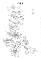
- the portable device 11 includes a case 12, which is formed by a first case part 13, a second case part 14, and a cover 81.
- the first case part 13 has an upper portion, which is open, and a lower portion.
- the second case part 14 has a lower portion, which is open and fixed to the first case part 13 so as to cover the open upper portion of the first case part 13.
- the cover 81 covers the lower portion of the first case part 13.
- the first case part 13, the second case part 14, and the cover 81 form a box as shown in Fig. 1B.
- the upper direction and lower direction of the portable device 11 will be based on the view in Fig. 1B throughout the drawings.
- the first case part 13 which is integrally injection molded from a synthetic resin, is box-shaped.
- a board compartment 21 is defined in the first case part 13.
- a square battery lid seat 22 is defined in a portion of the lower surface of the first case part 13.
- Bushing sockets 23 are formed in the four corners of the battery lid seat 22.
- a cylindrical bushing 24 is fitted into each bushing socket 23.
- a threaded hole 24a extends through the bushing 24.
- a circular and hollow battery compartment 25 is defined in the central portion of the battery lid seat 22.
- An annular groove 26 is formed between the battery compartment 25 and the four bushing sockets 23. The groove 26 receives a rubber O-ring 27.
- a through hole 25a extends through the bottom wall of the battery compartment 25.
- An opening 25b is formed in the side wall of the battery compartment 25.
- An arcuate stopper 28 is formed along the rim of the battery compartment 25 at the open end. The stopper 28 faces toward the inner side of the battery compartment 25.
- Board supports 29 are formed on the inner surfaces of the two opposing long walls of the first case part 13.
- the board supports 29 extend in a direction orthogonal to the bottom surface of the first case part 13,
- Each board support 29 has an upper end located at the same level as the upper surface of the battery compartment 25.
- a rectangular flange 30 extends along the peripheral surface of the first case part 13 at the middle of the first case part 13 in the heightwise direction.
- a plate-shaped tongue 31 extends from the portion of the flange 30 extending along the short wall of the first case part 13 located next to the battery compartment 25. The upper and lower surfaces of the tongue 31 are flush with the upper and lower surfaces of the flange 30 as viewed in Fig. 1A.
- a groove 32 having a square cross-section and functioning as a brittle portion, extends entirely across the tongue 31. Further, an engaging portion, or projection 33, extends across the lower surface of the tongue 31, as viewed in Fig. 3.
- Rails 34 having a predetermined length extend parallel to and below the flange 30 along the two opposite long walls of the first case part 13, as viewed in Fig. 3.
- a guide groove 35 is defined between the flange 30 and each rail 34.
- Recesses 36 are formed in the outer side of the two long walls and one short wall of the first case part 13 near the battery compartment 25. The recesses 36 are formed so that they are located at a level that differs from the level of the rails 34 in the vertical direction.
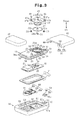
- the board compartment 21 of the first case part 13 accommodates a circuit board 42.
- the circuit board 42 is rectangular and shaped in correspondence with the board compartment 21.
- Push switches (micro switches) 43 are arranged in parallel in the longitudinal direction on the upper surface of the circuit board 42.
- Each push switch 43 has a housing 43a, which is fixed to the circuit board 42, and an actuator 43b, which is exposed from the housing 43a. The actuator 43b is pushed to close a contact (not shown) arranged in the housing 43a.
- the push switch 43 sends a detection signal indicating that the contact has closed to the microcomputer arranged in the circuit board 42.
- the microcomputer externally transmits control information for locking or unlocking the vehicle doors and an ID signal, which contains an ID code of the microcomputer, from a communication circuit arranged on the circuit board 42.
- a negative contact 44 and a positive contact 45 are arranged on the lower surface of the circuit board 42 as viewed in Fig. 1A.
- the negative contact 44 is exposed to the battery compartment 25 through the through hole 25a.
- the positive contact 45 is exposed to the battery compartment 25 through the opening 25b.
- the circuit board 42 is fitted into the board compartment 21 from above with the two push switches 43 facing an upward direction. Movement of the circuit board 42 into the board compartment 21 is restricted when the circuit board 42 abuts against the four board supports 29 and the upper surface of the battery compartment 25. The upper ends of the four board supports 29 and the upper surface of the battery compartment 25 are located at the same height from the bottom surface of the first case part 13. Thus, the circuit board 42 is held in a state parallel to the bottom surface of the first case part 13.
- a battery 46 which supplies the electronic components 41 on the circuit board 42 with operational power, is retained in the battery compartment 25.
- the battery 46 is a coin-type battery.
- a battery lid 47 is attached to the battery lid seat 22. More specifically, as shown in Fig. 3, the battery lid 47 is a square plate shaped in correspondence with the battery lid seat 22. Insertion holes 47a extend through the four corners of the battery lid 47. When attaching the battery lid 47 to the battery lid seat 22, the insertion holes 47a are aligned with the threaded holes 24a of the corresponding bushings 24.
- Screws 48 are inserted into the insertion holes 47a and mated with the threaded holes 24a of the bushings 24 to fix the battery lid 47 to the battery lid seat 22.
- Each screw 48 has a head, and each insertion, hole 47a includes a counterbore 47b for receiving the head of the corresponding screw 48 such that the head does not project out of the surface of the battery lid 47.
- the upper surface of the battery 46 functions as a negative electrode 46a and the peripheral surface of the battery 46 functions as a positive electrode 46b.
- the negative electrode 46a of the battery 46 is forced against the negative contact 44, which is exposed to the battery compartment 25 through the through hole 25a. This ensures that the negative electrode 46a of the battery 46 contacts the negative contact 44 under pressure.
- the positive electrode 46b of the battery 46 resiliently contacts the positive contact 45, which is exposed to the battery compartment 25 through the opening 25b.
- the second case part 14 which is integrally injection molded from a synthetic resin, is box-shaped.
- the opening of the second case part 14 defines a fitting portion 51 for receiving the first case part 13.
- the portion of the first case part 13 above the upper surface of the flange 30, as viewed in Fig. 1A, can be fitted into the fitting portion 51 in a state in which the circuit board 42 is attached to the first case part 13.
- a step 52 extends along the inner surface of the fitting portion 51.
- Two semicircular button receptacles 53 extend through the second case part 14 into the fitting portion 51. The two button receptacles 53 are spaced apart in the longitudinal direction of the second case part 14 facing opposite directions.
- the second case part 14 has two opposite long walls and two opposite short walls.
- One of the short walls and one of the long walls are thicker than the other one of the short walls and the other one of the long walls.
- An L-shaped cutaway portion 55 is formed in the corner formed by the thicker long and short walls.
- the cutaway portion 55 continuously extends from the thick long side for about two thirds of the short wall.
- an elongated groove 56 extends along the thick long wall.
- the elongated groove 56 has an end that opens to the cutaway portion 55.
- a hollow first lock member holder 57 is formed in the thick short wall.
- the first lock member holder 57 has an open portion 57a facing toward the cutaway portion 55.
- the first lock member holder 57 is in communication with the cutaway portion 55 through the open portion 57a.
- a positioning projection 57b is formed in the first lock member holder 57.
- the first lock member holder 57 of the second case part 14 retains a plate-like first lock member 58, or first lock member.
- the first lock member 58 is formed integrally from a metal material and includes a main portion 58a and an engagement portion 58b extending from the main portion 58a.
- the main portion 58a includes an insertion hole 58c for insertion of the positioning projection 57b formed in the first lock member holder 57.
- the first lock member 58 is arranged so that the positioning projection 57b is inserted into the insertion hole 58c, and the engagement portion 58b extends into the L-shaped cutaway portion 55 of the second case part 14 through the open portion 57a. Referring to Fig.
- the tongue 31 of the first case part 13 closes the opening of the first lock member holder 57 in the second case part 14.
- the first lock member 58 is retained in the first lock member holder 57.
- two semicircular push buttons 61 are respectively inserted into the two button receptacles 53 from the inner side of the second case part 14.
- the two push buttons 61 are connected to each other by a U-shaped connection member 62, which is arranged in the connection groove 54 of the second case part 14.
- the push buttons 61 and the connection member 62 are integrally injection molded from a synthetic resin.
- the push buttons 61 and the connection member 62 are flush with the inner surface of the second case part 14.
- Fig. 1 when arranged in the button receptacles 53 and connection groove 54 of the second case part 14, the push buttons 61 and the connection member 62 are flush with the inner surface of the second case part 14.
- connection member 62 includes two arms 62a, which are respectively connected to the two push buttons 61, and a link 62b connected to the arms 62a.
- the arms 62a are flexibly connected to the arms 62a so that the two push buttons 61 can be pushed independently from each other.
- a box-shaped packing 71 having an open lower portion as viewed in Fig. 1A is arranged between the first case part 13 and the second case part 14.
- the packing 71 is formed integrally from a rubber material, such as nitrite rubber, urethane rubber, or silicon rubber.
- the packing 71 includes a main body 71a, which has an open lower portion, and a lip 71b, which extends along the periphery of open end of the main body 71a.
- the main body 71a is shaped in correspondence with the inner side of the step 52 in the second case part 14, and the lip 71b is arranged on the step 52.
- the lip 71b is arranged between the open end surface of the first case part 13 and the open end surface of the fitting portion 51 in a state slightly compressed in the vertical direction. This seals the first case part 13 and the second case part 14 in a manner impervious to liquids.
- the packing 71 When the packing 71 is arranged between the first case part 13 and the second case part 14, the upper surface of the main body 71a is held in contact with the opposing inner surface of the second case part 14.
- the two push buttons 61 and the connection member 62 are held in a state accommodated in the two button receptacles 53 and the connection groove 54.
- Contact of the two push buttons 61 and the connection member 62 with the main body 71a restricts the downward movement of the two push buttons 61 and the connection member 62.
- the main body 71a resiliently deforms in an inward direction. This pushes the actuators 43b of the corresponding push switches 43 on the circuit board 42 with the main body 71a of the packing 71.
- the main body 71a separates the two button receptacles 53 and the two push buttons 61 from the inner side of the second case part 14, which accommodates the circuit board 42 in the board compartment 21.
- liquid such as water
- the main body 71a is formed integrally with the lip 71b, which is held between the open end surface of the first case part 13 and the open end surface of the fitting portion 51 in a slightly compressed state, liquid entering the button receptacles 53 through gaps formed around the push buttons 61 does not enter the inner side of the packing 71.
- the cover 81 includes a fixed cover piece 82 and a movable cover piece 83.
- the movable cover piece 83 covers the battery compartment 25 and the fixed cover piece 82 covers the remaining portion of the first case part 13.
- the fixed cover piece 82 and the movable cover piece 83 form a box having an open upper portion.
- the fixed cover piece 82 is integrally injection molded from a synthetic resin.
- the fixed cover piece 82 includes a bottom wall 82a and a U-shaped side wall 82b extending along the periphery of the bottom wall 82a.
- the fixed cover piece 82 has an open lateral side.
- a U-shaped step 84 extends along the inner surface of the side wall 82b.
- Three projections 85 are formed on the inner surfaces of the side wall 83b. The projections 85 are arranged in correspondence with the three recesses 36 of the first case part 13.
- One of the two opposing short walls of the fixed cover piece 82 is thicker than the other one.
- An elongated groove 86 is formed in the thicker short wall.
- the elongated groove 86 has an open end at the open lateral side of the fixed cover piece 82. Further, the elongated groove 86 has a width that is the same as that of the elongated groove 56 in the second case part 14.
- the fixed cover piece 82 is joined with the first case part 13, and the three projections 85 are engaged with the three recesses 36 to fasten the fixed cover piece 82 to the first case part 13.
- the movable cover piece 83 is integrally injection molded from a synthetic resin.
- the movable cover piece 83 includes a bottom wall 83a and a U-shaped side wall 83b extending along the periphery of the bottom wall 82a.
- the movable cover piece 83 has an open lateral, side.
- One of the two opposing long walls of the movable cover piece 83 is thicker than the other one.
- the movable cover piece 83 has an L-shaped cutaway portion 87 at a corner formed by the thicker long wall and the adjacent short wall. When the movable cover piece 83 is attached to the first case part 13, the cutaway portion 87 is arranged in correspondence with the cutaway portion 55 of the second case part 14.
- An elongated groove 88 extends along the thicker long wall of the movable cover piece 83. One end of the elongated groove 88 opens into the cutaway portion 87.
- a first step 89 extends along the inner side of the thicker long wall on the bottom surface of the movable cover piece 83.
- a second step 90 extends along the inner sides of the thinner long wall and the short wall on the bottom surface of the movable cover piece 83.
- a rail 91 extends parallel to the long walls along each of the steps 89 and 90. The two rails 91 are inserted into and guided by the two guide grooves 35 of the first case part 13.
- An engaged portion, or recess 92 which is engageable with the projection 33, is formed in the second step 90 in a portion corresponding to the short wall.
- the movable cover piece 83 is attached to the first case part 13 in a detachable manner by inserting the two rails 91 into the two guide grooves 35 of the first case part 13 and sliding the movable cover piece 83 toward the fixed cover piece 82.
- the movement of the movable cover piece 83 in the attaching direction is restricted by the abutment of the movable cover piece 83 against the fixed cover piece 82.
- the engagement of the rails 91 of the movable cover piece 83 with the corresponding rails 34 of the first case part 13 prevents the movable cover piece 83 from falling off the first case part 13.
- the projection 33 of the first case part 13 is engaged with the recess 92 of the movable cover piece 83. This restricts movement of the movable cover piece 83 in a detaching direction of the movable cover piece 83 and prevents the movable cover piece 83 from falling off the first case part 13.
- a key plate holder 93 is defined by the elongated groove 56 of the second case part 1.4, the side surface of the flange 30 of the first case part 13 that is flush with the inner surface of the elongated groove 56, the elongated groove 86 of the fixed cover piece 82, and the elongated groove 88 of the movable cover piece 83. As shown in Figs.
- the L-shaped cutaway portion 55 of the second case part 14 and the L-shaped cutaway portion 87 of the movable cover piece 83 define a key inlet 94.
- the inner surfaces of the second case part 14, the first case part 13, and the movable cover piece 83 that are exposed in the key inlet 94 define a grip holder 95.
- the grip holder 95 and the key plate holder 93 define a mechanical key holder 96 for accommodating a mechanical key 101.
- the mechanical key 101 is an emergency key used when the battery is drained or when the portable device 11 is not functioning properly.
- the mechanical key 101 is used to mechanically lock and unlock a vehicle door,
- the mechanical key 101 is L-shaped and includes a key plate 102 and a grip 103 fixed to one end of the key plate 102.
- the key plate 102 has a width and length set so that it can be accommodated in the key plate holder 93 of the case 12.
- the grip 103 extends orthogonal to the key plate 102 and is accommodated in the grip holder 95 of the case 12.
- the outer surface of the grip 103 extends continuously from the outer surface of the case 12, as shown in Fig. 1B.
- the outer surface of the grip 103 serves as part of an ornamental surface of the case 12.
- the end of the grip 103 opposite the end connected to the key plate 102 includes a second lock member holder 104.
- the second lock member holder 104 is arranged to correspond with the open portion 57a of the first lock member holder 57.
- the second lock member holder 104 accommodates a second lock member 105, which is movable in the direction the grip 103 extends.
- a coil spring 106 is arranged between the second lock member 105 and the surface of the second lock member holder 104 opposed to second lock member 105. The force of the coil spring 106 constantly urges the second lock member 105 outward from the second lock member holder 104.
- a lever slot 107 which is in communication with the second lock member holder 104, is formed in the surface of the grip 103.
- a slide lever 108 extends through the lever slot 107.
- the slide lever 108 has one end fixed to the second lock member 105 and another end exposed from the grip 103.
- the slide lever 108 moves integrally with the second lock member 105.
- the movement of the second lock member 105 and the slide lever 108 in the extending direction of the grip 103 is restricted by the abutment of the slide lever 108 against the wall of the lever slot 107.
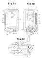
- the slide lever 108 moves the second lock member 105 between a lock position shown by the broken lines in Fig. 7C and an unlock position shown by the solid lines in Fig. 7C.
- the force of the coil spring 106 projects the second lock member 105 out of the grip 103.
- the second lock member 105 extends into the first lock member holder 57 through the open portion 57a of the case 12 and engages the engagement portion 58b of the first lock member 58.
- the second lock member 105 is located at the lock position.
- the engagement of the second lock member 105 with the engagement portion 58b of the first lock member 58 restricts the removal of the mechanical key 101 from the mechanical key holder 96.
- the second lock member 105 is moved inward into the second lock member holder 104 against the force of the coil spring 106 to disengage the second lock member 105 from the first lock member 58.
- the mechanical key 101 is removable from the mechanical key holder 96.
- the second case part 14 is first arranged on a table with the fitting portion 51 facing upwards.
- the two push buttons 61 and the connection member 62 are arranged in the two button receptacles 53 and the connection groove 54 of the second case part 14. In this state, the push buttons 61 are flush with the inner surface of the second case part 14.
- the packing 71 With its opening facing upwards, the packing 71 is arranged in the fitting portion 51. In this state, the lip 71b of the packing 71 is held on the step 52 of the second case part 14.
- the circuit board 42 is fitted into the board compartment 21 of the first case part 13.
- the two push switches 43 are exposed, and the negative contact 44 and positive contact 45 are arranged to correspond to the battery compartment 25.
- the first case part 13 is fitted into the fitting portion 51 of the second case part 14 with the circuit board 42 held in the board compartment 21.
- the movement of the first case part 13 into the second case part 14 is restricted when the flange 30 of the first case part 13 abuts against the open end surface of the second case part 14.
- thermal welding is performed to join the flange 30 of the first case part 13 with the open end surface of the second case part 14.
- laser welding is performed with a laser welding device to join the first case part 13 and the second case part 14.
- the battery 46 is arranged in the battery compartment 25, and the O-ring 27 is attached to the groove 26 of the battery lid seat 22. Further, the battery lid 47 is fixed to the battery lid seat 22 by fastening the screws 48 to the threaded holes 24a of the bushings 24. This holds the battery 46 in the battery compartment 25, and fixes the battery lid 47 to the first case part 13.
- the fixed cover piece 82 is placed on the first case part 13, and the three projections 85 are engaged with the three recesses 36. This fastens the fixed cover piece 82 to the first case part 13.
- the movable cover piece 83 is arranged beside the first case part 13 for attachment.
- the two rails 91 formed in the movable cover piece 83 are inserted into the two guide grooves 35 of the first case part 13.
- the movement of the movable cover piece 83 toward the fixed cover piece 82 is restricted when the side wall 83b and bottom wall 83a of the movable cover piece 83 abut against the side wall 82b and bottom wall 82a of the fixed cover piece 82.
- the recess 92 of the movable cover piece 83 is engaged with the projection 33 of the first case part 13. This restricts removal of the movable cover piece 83 and prevents the movable cover piece 83 from moving away from the fixed cover piece 82.
- the attachment of the movable cover piece 83 to the first case part 13 forms the key plate holder 93, the grip holder 95, and the key inlet 94.
- the slide lever 108 is operated to hold the second lock member 105 at the unlock position.
- the mechanical key 101 is inserted into the key inlet 94 from the key plate 102.
- the movement of the mechanical key 101 into the mechanical key holder 96 is restricted by the abutment of the grip 103 against the outer wall of the fitting portion 51, the edge of the elongated groove 56 in the second case part 14, the flange 30 of the first case part 13, and the edge of the elongated groove 88 in the movable cover piece 83.
- the second lock member 105 is located at a position corresponding to the space between the open portion 57a of the first lock member holder 57 and the engagement portion 58b of the first lock member 58. Then, the slide lever 108 is released, and the force of the coil spring 106 moves the second lock member 105 to the lock position so that the distal end of the second lock member 105 engages the engagement portion 58b of the first lock member 58. As a result, the mechanical key 101 is prevented from falling out of the mechanical key holder 96.
- a laser welding device 111 is used to thermally weld and join the first case part 13 and the second case part. 14 to each other in a superimposed state
- the laser welding device 111 will first be briefly described. Referring to Fig. 8, the laser welding device 111 generates a laser beam L with a laser beam generator 112. The laser beam L travels through an optical fiber 113 and a converging lens 114. Then, the laser beam L is directed toward welded portions of two resin parts that are joined with each other.
- the laser beam source used for such laser welding may be an yttrium aluminum garnet (YAG) laser, a glass laser, a ruby laser, a helium-neon gas laser, an argon laser, a fiber laser, or a semiconductor laser. Further, the laser beam generator 112 is fixed to a housing (not shown) of the laser welding device 111.
- the converging lens 114 is driven by a drive device (not shown) and is movable in an XYZ coordinate system in the directions of the X, Y, and Z axes.
- Two parts in the preferred embodiment, the first case part 13 and the second case part 14
- the drive device is driven to move the converging lens 114 relative to the parts in order to direct the laser beam L toward the joining portions of the parts.
- the parts holder may be moved.
- the synthetic resin used to form the first case part 13 and second case part 14 may be a non-crystalline resin, such as polystyrene, polyethylene, and polycarbonate, or a crystalline resin, such as polypropylene, polybutylene terephthalate, polyethylene terephthalate, polyamide, and polyacetal. In the preferred embodiment, polycarbonate is used.
- the first case part 13 transmits the laser beam L, or has a transmittance with respect to the spectrum of the laser beam L.
- the second case part 14 absorbs the spectrum of the laser beam L, or has an absorbance with respect to the spectrum of the laser beam L.
- the transmittance and absorbance of the first case part 13 and second case part 14 are dependent on the amount and dispersion of an additive (colorant), such as dye and pigment, in the synthetic resin forming the first case part 13 and second case part 14.
- pigment of a predetermined color e.g., carbon black
- the amount and dispersion of the absorption colorant for the synthetic resin is determined so that the second case part 14 has the required laser beam absorbance for generating the necessary heat.
- the laser light absorption colorant may be a pigment colorant or a dye colorant. Such pigment colorant and dye colorant may be combined to generate the necessary heat. This would enable the welding conditions to be flexible.
- Carbon black which is described above, is generally used as a pigment colorant.
- the cover 81 (i.e., the fixed cover piece 82 and the movable cover piece 83) is formed with the same synthetic resin as the second case part 14 and has the same color as the second case part 14.
- the second case part 14 and the cover 81 have the same color to improve the aesthetic appeal of the portable device 11.
- the type, amount, and dispersion of the pigment for the second case part 14 and cover 81 are determined so that the second case part 14 and cover 81 are non-transparent to visible light, that is, so that the second case part 14 and cover 81 have a visible light transmittance of less than 10%.
- the first case part 13 includes a first resin portion 13a and a second resin portion 13b.
- the first and second resin portions 13a and 13b are integrally molded by performing two-color molding or insert molding,
- the first resin portion 13a is box-shaped and includes the board compartment 21. Dye having the same color as the pigment added to the second case part 14 is added as a colorant to the synthetic resin forming the first resin portion 13a.
- the first resin portion 13a is non-transparent to visible light. More specifically, the type, amount, and dispersion of the pigment and dye for the synthetic resin of the first resin portion 13a are determined so that the transmittance of visible light is less than 10%.
- the first resin portion 13a may have any color as long as it is non-transparent to visible light.
- the first, resin portion 13a substantially does not undergo laser welding. Thus, there are no requirements with regard to the transmittance and absorbance of the laser beam L for the first resin portion 13a. This eliminates the need for adjustment of parameters related with the transmittance and absorbance of the laser beam L. Further, the first resin portion 13a does not have to transmit the laser beam L.
- the second resin portion 13b is box-shaped and surrounds the first resin portion 13a. Part of the second resin portion 13b forms the flange 30. Further, the second resin second 13b is colorless and transparent to visible light.
- Dye having a predetermined color may be added to the synthetic resin of the second resin portion 13b.
- the type, amount, and dispersion of the dye for the synthetic resin of the second resin portion 13b are determined so that the second resin portion 13b is colored and transparent. In any case, the type, amount, and dispersion of the dye for the synthetic resin of the second resin portion 13b are determined so that the transmittance of visible light is 10% or greater.
- the range for the transmittance of visible light for the second resin portion 13b is 10% to 100%.
- the visible light transmittance is 10% or less, it becomes difficult to visually inspect welded portions (welded state) of the second resin portion 13b and the open end surface of the second case part 14.
- the type, amount, and dispersion of the dye for the synthetic resin of the second resin portion 13b are determined to ensure the required transmittance with respect to the laser beam L so that the second resin portion 13b sufficiently transmits the laser beam L,
- the second resin portion 13b differs from the second case part 14 in that a dye is added to the synthetic resin forming the second resin portion 13b.
- a dye is added to the synthetic resin forming the second resin portion 13b. This is for the following reasons.
- a pigment does not dissolve in a synthetic resin and is dispersed as grains (coagulations). Thus, the pigment absorbs and diffuses (reflects) the laser beam L and renders the transmission of the laser beam L difficult.
- a dye is dissolved in the synthetic resin at a molecular level. This enables uniform coloring and stabilizes the color phase.
- a dye has a high light transmission property although this is affected by the synthetic resin to which the dye is added.
- pigment is added to the synthetic resin of the second case part 14, and dye is added to the synthetic resin of the second resin portion 13b in the first case part 13.
- the first resin portion 13a of the first case part 13 substantially does not undergo laser welding.
- dye or pigment of a predetermined color may be added to the synthetic resin of the first resin portion 13a.
- first case part 13 and the second case part 14 With the laser welding device 111 will now be described.
- the first case part 13 In a state in which the circuit board 42 is facing toward the second case part 14, the first case part 13 is fitted into the fitting portion 51 of the second case part 14.
- the flange 30 of the first case part 13 In a state in which the flange 30 of the first case part 13 is engaged with the open end surface of the second case part 14, the first case part 13 and second case part 14 are supported by and fixed to the parts holder of the laser welding device 111.
- a laser beam L is emitted and directed via the converging lens 114 toward the flange 30 from the first case part 13. More specifically, as shown by arrow ⁇ in Fig. 10, the laser beam L is directed toward the flange 30 while continuously moving the converging lens 114 along the flange 30 of the first case part 13.
- the laser beam L emitted through the converging lens 114 and transmitted through the flange 30 reaches the open end surface of the second case part 14.
- the energy of the laser beam L is absorbed at the portion of the open end surface of the joined with the flange 30.
- the absorption of the laser energy generates heat, which fuses the joined portions (joined surfaces) of the flange 30 and the second case part 14.
- the fused portions, or the joined portions of the flange 30 and the second case part 14 are cooled and solidified.
- the flange 30 of the first case part 13 with the open end surface of the second case part 14 may be partially joined with each other at a number of locations.
- the flange 30 functions as the joined portion of the first case part 13, and the open end surface of the second case part 14 as the joined portion of the second case part 14.
- the second resin portion 13b (i.e., the flange 30) of the first case part 13 is colorless and transparent. This enables visual inspection of the welded portion between the flange 30 and the second case part 14 through the first case part 13. Accordingly, the joining of the first case part 13 and the second case part 14 may be checked during the manufacturing of the portable device 11.
- the flange 30 of the first case part 13 and the open end surface of the second case part 14 may be partially joined with each other at a number of locations.
- the flange 30 functions as the joined portion of the first case part 13, and the open end surface of the second case part 14 as the joined portion of the second case part 14.
- thermally welding synthetic resin material include ultrasonic welding, vibration welding, and hot plate welding.
- Ultrasonic welding, vibration welding, and hot plate welding may be performed to join the first case part 13 and the second case part 14. However, it is preferred that laser welding be performed to join the first case part 13 and the second case part 14.
- Ultrasonic welding is performed by simultaneously applying pressure and fine vibrations to the contacting surfaces of the two resin members that are welded together. This generates high friction heat and fuses the resin. However, the heating produces fine resin particles. Further, the fine vibrations may generate vibration stress that afflicts damages to the first case part 13, the second case part 14, and the circuit board 42. Vibration welding is performed by applying pressure and friction to one of two members that are welded with each other. This generates high friction heat that fuses the resin. Although the vibration stress that is generated is less as compared with ultrasonic welding, the heating produces fine particles. Hot plate welding is performed to apply heat to the entire product with a heater plate or the like in order to cause fusion. Hot plate welding does not produce resin particles. However, heat cannot be generated locally. Thus, the application of hot plate heating to a product containing the circuit board 42 is difficult. Laser welding does not cause such problems and does not affect the first case part 13, the second case part 14, and the circuit board 42 with heat or vibrations in such a manner.
- first case part 13 may be pressed toward the second case part 14 with a pressing means, such as a roller (not shown).
- the pressing means follows the movement of the converging lens 114. Further, the pressing means continues to apply pressure until the joined portions of the first case part 13 and the second case part 14 are cooled. This prevents the generation of voids (bubbles) in the joined portions of the first case part 13 and the second case part 14.
- the first embodiment has the advantages described below.
- the second embodiment differs from the first embodiment in that the first case part is formed by joining two separate members.
- first case part is formed by joining two separate members.
- like or same reference numerals are given to those components that are the same as the corresponding components of the first embodiment. Such components will not be described in detail.
- the first case part 13 includes a first resin member 121 and a second resin member 122, which are joined with each other.
- the first resin member 121 is box-shaped and includes the board compartment 21 and part of the flange 30.
- a rectangular frame-like first flange portion 123 which is shown in Fig. 12A, is formed around the first resin member 121.
- the first flange portion 123 which includes an upper surface defining an inclined surface 123a, has a thickness that decreases toward the outer side.
- a dye having the same color as the pigment added to the second case part 14 is added as a colorant to the synthetic resin forming the first resin merger 121.
- the type, amount, and dispersion of the pigment and dye for the synthetic resin of the first resin member 121 are determined so that the first resin member 121 is non-transparent to visible light, that is, the transmittance of visible light in the first resin member 121 is less than 10%.
- the first resin member 121 may have any color as long as it is non-transparent to visible light.
- the first resin member 121 substantially does not undergo laser welding. Thus, there are no requirements with regard to the transmittance and absorbance of the laser beam L for the first resin member 121. This eliminates the need for adjustment of parameters related to the and absorbance of the laser beam L. Further, the first resin member 121 does not have to transmit the laser beam L.
- the second resin member 122 is frame-shaped and serves as a second, flange portion that includes the tongue 31.
- a step 124 is formed on one side of the second resin member 122 in correspondence with the first flange portion 123 of the first resin member 121.
- the step 124 which defines an inclined surface 124a at one side, has a thickness that decreases toward the inner side.
- the second resin member 122 is attached to the first resin member 121 so that the inclined surface 124a faces toward the inclined surface 123a of the first resin member 121. In this state, the inclined surface 124a comes into contact with the inclined surface 123a of the first flange portion 123.
- the first flange portion 123 of the first resin member 121 forms the flange 30 with the second resin member 122 (second flange portion).
- the second resin member 122 is colorless and transparent to visible light.
- Dye having a predetermined color may be added to the synthetic resin of the second resin member 122.
- the type, amount, and dispersion or the dye for the synthetic resin of the second resin member 122 are determined so that the second resin member 122 is colored and transparent.
- the type, amount, and dispersion of the dye for the synthetic resin of the second resin member 122 are determined so that the transmittance of visible light is 10% or greater. That is, the range for the transmittance of visible light for the second resin member 122 is 10% to 100%.
- the visible light transmittance is 10% or less, it becomes difficult to visually inspect welded portions (welded state) of the second resin member 122 and the open end surface of the second case part 14.
- the type, amount, and dispersion of the dye for the synthetic resin of the second resin member 122 are determined to ensure the required transmittance with respect to the laser beam L.
- the first and second resin members 121 and 122 are welded to each other with the laser welding device 111. More specifically, in a state in which the first resin member 121 and the second resin member 122 are joined with each other, a laser beam L is emitted and transmitted through the second resin member 122. The laser beam L is directed toward the flange 30 while continuously moving the converging lens 114 along the second resin member 122. This joins the inclined surface 123a of the first resin member 121 entirely with the inclined surface 124a of the second resin member 122.
- the second resin member 122 is colorless and transparent. This enables visual inspection of the welded portions of the second resin member 122 and the first resin member 121 from the side of the second resin member 122.
- the first case part 13 which is formed by joining the first resin member 121 and the second resin member 122, is laser welded and joined with the second case part 14 in the same manner as the first embodiment.
- the joining of the first resin member 121 and the second resin member may be welded together by performing ultrasonic welding, vibration welding, or hot plate welding.
- the second embodiment also hides the circuit board 42 and ensures quality related with the joining (welding) of the first case part 13 and the second case part 14. Further, the first resin member 121 and the second resin member 122 are joined with each other through thermal welding. Thus, fasteners such as bolts or screws are not necessary to join the first resin member 121 and the second resin, member 122. Further, space for such fasteners does not have to be provided by the first resin member 121 and the second resin member 122. This enables the size of the case 12 to be reduced and minimizes the number of components.
- the present invention is embodied in a case of a portable device.
- the present invention may be embodied in a case, which incorporates electronic components, for other devices.
Landscapes
- Engineering & Computer Science (AREA)
- Mechanical Engineering (AREA)
- Physics & Mathematics (AREA)
- Optics & Photonics (AREA)
- Health & Medical Sciences (AREA)
- Electromagnetism (AREA)
- Toxicology (AREA)
- Manufacturing & Machinery (AREA)
- General Physics & Mathematics (AREA)
- Casings For Electric Apparatus (AREA)
- Lock And Its Accessories (AREA)
Abstract
Description
- The present invention relates to a portable device for performing wireless communication with a predetermined communication subject.
- Vehicles, such as automobiles, nowadays often incorporate electronic key systems to improve vehicle operation convenience. Such an electronic key system locks and unlocks doors and enables the starting of the engine when a unique ID code transmitted from a portable device, which is carried by a user, is identical to an ID code registered in the vehicle. The portable device has a case for accommodating a circuit board on which various electronic components are mounted and a battery for supplying power to the electronic components on the circuit board.
-
Japanese Laid-Open Patent Publication No. 2005-235837 - The first case part and the second case part are fastened to each other only by the engagement between the projections and the recesses. Thus, a person other than the user may be able to disassemble the case of the portable device in a relatively simple manner. Such a person may disassemble the case by the projections of the first case part from the recesses of the second case part in order to remove the circuit board from the case. If the first and second case parts are fastened again to each other after the circuit board is removed, the user would not be aware for a while of tampering with the circuit board.
- The present invention provides a case and portable device enabling tampering of the circuit board to be visually recognizable.
- One aspect of the present invention is a case for accommodating a predetermined component. The case includes a first case part formed from a synthetic resin. The first case part includes a non-transparent portion that is non-transparent to visible light and a transparent portion that is transparent to visible light, arranged adjacent to and outward from the non-transparent portion, and transmissible to laser light. A second case part (14) that is transparent to visible light is formed from a synthetic resin. The second case part absorbs laser light and is superimposed with the first case part in a state joined with the transparent portion.
- Another aspect of the present invention is a portable device for performing wireless communication with a predetermined communication subject. The portable device includes a circuit board, on which an electronic component used to perform wireless communication is mounted, and a case for accommodating the circuit board. The case includes a first case part formed from a synthetic resin. The first case part includes a non-transparent portion that is non-transparent to visible light and a transparent portion that is transparent to visible light, arranged adjacent to and outward from the non-transparent portion, and transmissible to laser light. A second case part is transparent to visible light and formed from a synthetic resin. The second case part absorbs laser light and is superimposed with the first case part in a state joined with the transparent portion.
- The invention, together with objects and advantages thereof, may best be understood by reference to the following description of the presently preferred embodiments together with the accompanying drawings in which:
- Fig. 1A is a cross-sectional view or a portable device according to a preferred embodiment of the present invention;
- Fig. 1B is a schematic perspective view showing the portable device;
- Fig. 2 is an exploded perspective view showing the portable device;
- Fig. 3 is an exploded perspective view showing the portable device reversed from the state of Fig. 2;
- Fig. 4 is a cross-sectional view taken along line IV-IV in Fig. 1A;
- Fig. 5 is a side view showing the portable device when viewed in the direction of arrow V in Fig. 1B;
- Fig. 6A is a side view showing the portable device in a state in which a mechanical key is removed therefrom when viewed in the direction of arrow VI in Fig. 1B;
- Fig. 6B is a schematic perspective view showing the portable device in a state in which the mechanical key is removed therefrom;
- Fig. 7A is a plan view showing the portable device in a state in which a second case part is removed therefrom;
- Fig. 7B is a lower view showing the second case part and the mechanical key;
- Fig. 7C is an enlarged view of Fig. 7B showing an engagement structure for second case part and the mechanical key;
- Fig. 8 is a schematic diagram showing a laser welding device;
- Fig. 9 is a cross-sectional view taken along line IX-IX in Fig. 1 and shows a first resin portion and a second resin portion of the first case part;
- Fig. 10 is a lower view showing a laser beam emission route along the case in a state in which a cover is removed therefrom;
- Fig. 11 is a cross-sectional view taken along line IX-IX in Fig. 1 and shows first and second resin members in a joined state according to a second embodiment of the present invention;
- Fig. 12A is an exploded perspective view showing the first and second resin members; and
- Fig. 12B is a schematic perspective view showing the second resin member from the opposite side of Fig. 12A.
- A
portable device 11, which performs wireless communication with a predetermined communication subject, according to a preferred embodiment of the present invention will now be discussed. The portable device is used in an electronic, key system together with a lock controller, which is installed in a vehicle. When a user, who is carrying theportable device 11, enters within a predetermined range set for the vehicle, theportable device 11 receives a request signal transmitted from the lock controller. In response, theportable device 11 transmits an ID signal, which contains an ID code of theportable device 11. The lock controller receives the ID signal theportable device 11 and compares the ID code contained in the ID signal with an ID code of the vehicle that is stored in the lock controller. When the ID codes are identical, the lock controller unlocks the vehicle doors. - Referring to Fig. 1A, the
portable device 11 includes acase 12, which is formed by afirst case part 13, asecond case part 14, and acover 81. As viewed in Fig. 1A, thefirst case part 13 has an upper portion, which is open, and a lower portion. Thesecond case part 14 has a lower portion, which is open and fixed to thefirst case part 13 so as to cover the open upper portion of thefirst case part 13. Thecover 81 covers the lower portion of thefirst case part 13. When assembled together, thefirst case part 13, thesecond case part 14, and thecover 81 form a box as shown in Fig. 1B. Hereafter, the upper direction and lower direction of theportable device 11 will be based on the view in Fig. 1B throughout the drawings. - Referring to Fig. 2, the
first case part 13, which is integrally injection molded from a synthetic resin, is box-shaped. Aboard compartment 21 is defined in thefirst case part 13. As shown in Fig. 3, a squarebattery lid seat 22 is defined in a portion of the lower surface of thefirst case part 13.Bushing sockets 23 are formed in the four corners of thebattery lid seat 22. Acylindrical bushing 24 is fitted into eachbushing socket 23. A threadedhole 24a extends through thebushing 24. - A circular and
hollow battery compartment 25 is defined in the central portion of thebattery lid seat 22. Anannular groove 26 is formed between thebattery compartment 25 and the fourbushing sockets 23. Thegroove 26 receives a rubber O-ring 27. As shown in Fig. 2, a throughhole 25a extends through the bottom wall of thebattery compartment 25. Anopening 25b is formed in the side wall of thebattery compartment 25. Anarcuate stopper 28 is formed along the rim of thebattery compartment 25 at the open end. Thestopper 28 faces toward the inner side of thebattery compartment 25. - Board supports 29 are formed on the inner surfaces of the two opposing long walls of the
first case part 13. The board supports 29 extend in a direction orthogonal to the bottom surface of thefirst case part 13, Eachboard support 29 has an upper end located at the same level as the upper surface of thebattery compartment 25. - A
rectangular flange 30 extends along the peripheral surface of thefirst case part 13 at the middle of thefirst case part 13 in the heightwise direction. A plate-shapedtongue 31 extends from the portion of theflange 30 extending along the short wall of thefirst case part 13 located next to thebattery compartment 25. The upper and lower surfaces of thetongue 31 are flush with the upper and lower surfaces of theflange 30 as viewed in Fig. 1A. Agroove 32 having a square cross-section and functioning as a brittle portion, extends entirely across thetongue 31. Further, an engaging portion, orprojection 33, extends across the lower surface of thetongue 31, as viewed in Fig. 3. -
Rails 34 having a predetermined length extend parallel to and below theflange 30 along the two opposite long walls of thefirst case part 13, as viewed in Fig. 3. Aguide groove 35 is defined between theflange 30 and eachrail 34.Recesses 36 are formed in the outer side of the two long walls and one short wall of thefirst case part 13 near thebattery compartment 25. Therecesses 36 are formed so that they are located at a level that differs from the level of therails 34 in the vertical direction. - Referring to Fig. 1, the
board compartment 21 of thefirst case part 13 accommodates acircuit board 42. A microcomputer (now shown) and variouselectronic components 41, such as electronic devices that form a communication circuit, are connected to thecircuit board 42. Thecircuit board 42 is rectangular and shaped in correspondence with theboard compartment 21. Push switches (micro switches) 43 are arranged in parallel in the longitudinal direction on the upper surface of thecircuit board 42. Eachpush switch 43 has ahousing 43a, which is fixed to thecircuit board 42, and anactuator 43b, which is exposed from thehousing 43a. Theactuator 43b is pushed to close a contact (not shown) arranged in thehousing 43a. As a result, thepush switch 43 sends a detection signal indicating that the contact has closed to the microcomputer arranged in thecircuit board 42. In response to the detection signal from thepush switch 43, the microcomputer externally transmits control information for locking or unlocking the vehicle doors and an ID signal, which contains an ID code of the microcomputer, from a communication circuit arranged on thecircuit board 42. - A
negative contact 44 and apositive contact 45 are arranged on the lower surface of thecircuit board 42 as viewed in Fig. 1A. When thecircuit board 42 is retained in theboard compartment 21, thenegative contact 44 is exposed to thebattery compartment 25 through the throughhole 25a. Further, when thecircuit board 42 is retained in theboard compartment 21, thepositive contact 45 is exposed to thebattery compartment 25 through theopening 25b. - The
circuit board 42 is fitted into theboard compartment 21 from above with the twopush switches 43 facing an upward direction. Movement of thecircuit board 42 into theboard compartment 21 is restricted when thecircuit board 42 abuts against the four board supports 29 and the upper surface of thebattery compartment 25. The upper ends of the four board supports 29 and the upper surface of thebattery compartment 25 are located at the same height from the bottom surface of thefirst case part 13. Thus, thecircuit board 42 is held in a state parallel to the bottom surface of thefirst case part 13. - A
battery 46, which supplies theelectronic components 41 on thecircuit board 42 with operational power, is retained in thebattery compartment 25. In the preferred embodiment, thebattery 46 is a coin-type battery. When thebattery 46 is retained in thebattery compartment 25, abattery lid 47 is attached to thebattery lid seat 22. More specifically, as shown in Fig. 3, thebattery lid 47 is a square plate shaped in correspondence with thebattery lid seat 22.Insertion holes 47a extend through the four corners of thebattery lid 47. When attaching thebattery lid 47 to thebattery lid seat 22, theinsertion holes 47a are aligned with the threadedholes 24a of the correspondingbushings 24. -
Screws 48 are inserted into theinsertion holes 47a and mated with the threadedholes 24a of thebushings 24 to fix thebattery lid 47 to thebattery lid seat 22. Eachscrew 48 has a head, and each insertion,hole 47a includes acounterbore 47b for receiving the head of thecorresponding screw 48 such that the head does not project out of the surface of thebattery lid 47. The upper surface of thebattery 46 functions as a negative electrode 46a and the peripheral surface of thebattery 46 functions as apositive electrode 46b. When thebattery lid 47 is fixed to thebattery lid seat 22, the negative electrode 46a of thebattery 46 is forced against thenegative contact 44, which is exposed to thebattery compartment 25 through the throughhole 25a. This ensures that the negative electrode 46a of thebattery 46 contacts thenegative contact 44 under pressure. Further, thepositive electrode 46b of thebattery 46 resiliently contacts thepositive contact 45, which is exposed to thebattery compartment 25 through theopening 25b. - Referring to Fig. 3, the
second case part 14, which is integrally injection molded from a synthetic resin, is box-shaped. The opening of thesecond case part 14 defines afitting portion 51 for receiving thefirst case part 13. The portion of thefirst case part 13 above the upper surface of theflange 30, as viewed in Fig. 1A, can be fitted into thefitting portion 51 in a state in which thecircuit board 42 is attached to thefirst case part 13. Astep 52 extends along the inner surface of thefitting portion 51. Twosemicircular button receptacles 53 extend through thesecond case part 14 into thefitting portion 51. The twobutton receptacles 53 are spaced apart in the longitudinal direction of thesecond case part 14 facing opposite directions. When thefirst case part 13 having thecircuit board 42 attached thereto is fitted into thefitting portion 51 of the second case part 1.4, the twobutton receptacles 53 are aligned with theactuators 43b of the push switches 43 on thecircuit board 42. AU-shaped connection groove 54 is formed in the inner surface of thesecond case part 14 so as to connect the twobutton receptacles 53. - The
second case part 14 has two opposite long walls and two opposite short walls. One of the short walls and one of the long walls are thicker than the other one of the short walls and the other one of the long walls. An L-shapedcutaway portion 55 is formed in the corner formed by the thicker long and short walls. Thecutaway portion 55 continuously extends from the thick long side for about two thirds of the short wall. Further, anelongated groove 56 extends along the thick long wall. Theelongated groove 56 has an end that opens to thecutaway portion 55. A hollow firstlock member holder 57 is formed in the thick short wall. The firstlock member holder 57 has anopen portion 57a facing toward thecutaway portion 55. The firstlock member holder 57 is in communication with thecutaway portion 55 through theopen portion 57a. A positioning projection 57b is formed in the firstlock member holder 57. - In a state in which the portion of the
first case part 13 above theflange 30 is fitted into thefitting portion 51 of thesecond case part 14 so that thesecond case part 14 comes into contact with theflange 30, thefirst case part 13 and the second,case part 14 are fastened together. In the preferred embodiment, the upper surface of theflange 30 and the lower surface of thesecond case part 14 are thermally welded together. In a state in which thefirst case part 13 and thesecond case part 14 are fastened to each other, theactuators 43b of the two push switches 43 on thecircuit board 42 aligned with the twobutton receptacles 53 of thesecond case part 14. - The first
lock member holder 57 of thesecond case part 14 retains a plate-likefirst lock member 58, or first lock member. Thefirst lock member 58 is formed integrally from a metal material and includes amain portion 58a and anengagement portion 58b extending from themain portion 58a. Themain portion 58a includes aninsertion hole 58c for insertion of the positioning projection 57b formed in the firstlock member holder 57. Thefirst lock member 58 is arranged so that the positioning projection 57b is inserted into theinsertion hole 58c, and theengagement portion 58b extends into the L-shapedcutaway portion 55 of thesecond case part 14 through theopen portion 57a. Referring to Fig. 4, when thefirst case part 13 and thesecond case part 14 are fastened to each other, thetongue 31 of thefirst case part 13 closes the opening of the firstlock member holder 57 in thesecond case part 14. Thus, in a state held between thetongue 31 and the opposing surface of the firstlock member holder 57, thefirst lock member 58 is retained in the firstlock member holder 57. - Referring to Fig. 2, two
semicircular push buttons 61 are respectively inserted into the twobutton receptacles 53 from the inner side of thesecond case part 14. The twopush buttons 61 are connected to each other by aU-shaped connection member 62, which is arranged in theconnection groove 54 of thesecond case part 14. Thepush buttons 61 and theconnection member 62 are integrally injection molded from a synthetic resin. As shown in Fig. 1, when arranged in thebutton receptacles 53 andconnection groove 54 of thesecond case part 14, thepush buttons 61 and theconnection member 62 are flush with the inner surface of thesecond case part 14. As shown in Fig. 2, theconnection member 62 includes twoarms 62a, which are respectively connected to the twopush buttons 61, and alink 62b connected to thearms 62a. Thearms 62a are flexibly connected to thearms 62a so that the twopush buttons 61 can be pushed independently from each other. - A box-shaped
packing 71 having an open lower portion as viewed in Fig. 1A is arranged between thefirst case part 13 and thesecond case part 14. The packing 71 is formed integrally from a rubber material, such as nitrite rubber, urethane rubber, or silicon rubber. The packing 71 includes amain body 71a, which has an open lower portion, and alip 71b, which extends along the periphery of open end of themain body 71a. Themain body 71a is shaped in correspondence with the inner side of thestep 52 in thesecond case part 14, and thelip 71b is arranged on thestep 52. - As shown in Fig. 1A, when the packing 71 is arranged between the
first case part 13 and thesecond case part 14, thelip 71b is arranged between the open end surface of thefirst case part 13 and the open end surface of thefitting portion 51 in a state slightly compressed in the vertical direction. This seals thefirst case part 13 and thesecond case part 14 in a manner impervious to liquids. - When the packing 71 is arranged between the
first case part 13 and thesecond case part 14, the upper surface of themain body 71a is held in contact with the opposing inner surface of thesecond case part 14. Thus, the twopush buttons 61 and theconnection member 62 are held in a state accommodated in the twobutton receptacles 53 and theconnection groove 54. Contact of the twopush buttons 61 and theconnection member 62 with themain body 71a restricts the downward movement of the twopush buttons 61 and theconnection member 62. When any of the twopush buttons 61 are pushed, themain body 71a resiliently deforms in an inward direction. This pushes theactuators 43b of the corresponding push switches 43 on thecircuit board 42 with themain body 71a of the packing 71. - In a state in which the packing 71 is arranged between the
first case part 13 and thesecond case part 14, themain body 71a separates the twobutton receptacles 53 and the twopush buttons 61 from the inner side of thesecond case part 14, which accommodates thecircuit board 42 in theboard compartment 21. Thus, even when liquid, such as water, enters thebutton receptacles 53 through gaps formed around the correspondingpush buttons 61, the liquid does not reach thecircuit board 42. Since themain body 71a is formed integrally with thelip 71b, which is held between the open end surface of thefirst case part 13 and the open end surface of thefitting portion 51 in a slightly compressed state, liquid entering thebutton receptacles 53 through gaps formed around thepush buttons 61 does not enter the inner side of the packing 71. - As shown in Fig. 1A, the
cover 81 includes a fixedcover piece 82 and amovable cover piece 83. Themovable cover piece 83 covers thebattery compartment 25 and the fixedcover piece 82 covers the remaining portion of thefirst case part 13. When joined with each other, the fixedcover piece 82 and themovable cover piece 83 form a box having an open upper portion. - Referring to Fig. 2, the fixed
cover piece 82 is integrally injection molded from a synthetic resin. The fixedcover piece 82 includes abottom wall 82a and aU-shaped side wall 82b extending along the periphery of thebottom wall 82a. The fixedcover piece 82 has an open lateral side. A U-shaped step 84 extends along the inner surface of theside wall 82b. Threeprojections 85 are formed on the inner surfaces of theside wall 83b. Theprojections 85 are arranged in correspondence with the threerecesses 36 of thefirst case part 13. - One of the two opposing short walls of the fixed
cover piece 82 is thicker than the other one. Anelongated groove 86 is formed in the thicker short wall. Theelongated groove 86 has an open end at the open lateral side of the fixedcover piece 82. Further, theelongated groove 86 has a width that is the same as that of theelongated groove 56 in thesecond case part 14. - The fixed
cover piece 82 is joined with thefirst case part 13, and the threeprojections 85 are engaged with the threerecesses 36 to fasten the fixedcover piece 82 to thefirst case part 13. - The
movable cover piece 83 is integrally injection molded from a synthetic resin. Themovable cover piece 83 includes abottom wall 83a and aU-shaped side wall 83b extending along the periphery of thebottom wall 82a. Themovable cover piece 83 has an open lateral, side. One of the two opposing long walls of themovable cover piece 83 is thicker than the other one. Themovable cover piece 83 has an L-shapedcutaway portion 87 at a corner formed by the thicker long wall and the adjacent short wall. When themovable cover piece 83 is attached to thefirst case part 13, thecutaway portion 87 is arranged in correspondence with thecutaway portion 55 of thesecond case part 14. - An
elongated groove 88 extends along the thicker long wall of themovable cover piece 83. One end of theelongated groove 88 opens into thecutaway portion 87. Afirst step 89 extends along the inner side of the thicker long wall on the bottom surface of themovable cover piece 83. Asecond step 90 extends along the inner sides of the thinner long wall and the short wall on the bottom surface of themovable cover piece 83. Arail 91 extends parallel to the long walls along each of thesteps rails 91 are inserted into and guided by the twoguide grooves 35 of thefirst case part 13. An engaged portion, orrecess 92, which is engageable with theprojection 33, is formed in thesecond step 90 in a portion corresponding to the short wall. - The
movable cover piece 83 is attached to thefirst case part 13 in a detachable manner by inserting the tworails 91 into the twoguide grooves 35 of thefirst case part 13 and sliding themovable cover piece 83 toward the fixedcover piece 82. The movement of themovable cover piece 83 in the attaching direction is restricted by the abutment of themovable cover piece 83 against the fixedcover piece 82. Further, the engagement of therails 91 of themovable cover piece 83 with thecorresponding rails 34 of thefirst case part 13 prevents themovable cover piece 83 from falling off thefirst case part 13. Additionally, theprojection 33 of thefirst case part 13 is engaged with therecess 92 of themovable cover piece 83. This restricts movement of themovable cover piece 83 in a detaching direction of themovable cover piece 83 and prevents themovable cover piece 83 from falling off thefirst case part 13. - Referring to Fig. 5, in a state in which the fixed
cover piece 82 and themovable cover piece 83 are attached to thefirst case part 13, akey plate holder 93 is defined by theelongated groove 56 of the second case part 1.4, the side surface of theflange 30 of thefirst case part 13 that is flush with the inner surface of theelongated groove 56, theelongated groove 86 of the fixedcover piece 82, and theelongated groove 88 of themovable cover piece 83. As shown in Figs. 6A and 6B, in a state in which the fixedcover piece 82 and themovable cover piece 83 are attached to thefirst case part 13, the L-shapedcutaway portion 55 of thesecond case part 14 and the L-shapedcutaway portion 87 of themovable cover piece 83 define akey inlet 94. As shown by the broken lines in Fig. 6B, the inner surfaces of thesecond case part 14, thefirst case part 13, and themovable cover piece 83 that are exposed in thekey inlet 94 define agrip holder 95. Thegrip holder 95 and thekey plate holder 93 define a mechanicalkey holder 96 for accommodating amechanical key 101. - The
mechanical key 101 is an emergency key used when the battery is drained or when theportable device 11 is not functioning properly. Themechanical key 101 is used to mechanically lock and unlock a vehicle door, - As shown in Fig. 2, the
mechanical key 101 is L-shaped and includes akey plate 102 and agrip 103 fixed to one end of thekey plate 102. Thekey plate 102 has a width and length set so that it can be accommodated in thekey plate holder 93 of thecase 12. Thegrip 103 extends orthogonal to thekey plate 102 and is accommodated in thegrip holder 95 of thecase 12. - When the
key plate 102 is accommodated in thekey plate holder 93 and thegrip 103 is accommodated in thegrip holder 95, that is, when themechanical key 101 is accommodated in the mechanicalkey holder 96, the outer surface of thegrip 103 extends continuously from the outer surface of thecase 12, as shown in Fig. 1B. Thus, the outer surface of thegrip 103 serves as part of an ornamental surface of thecase 12. - Referring to Figs. 78 and 7C, the end of the
grip 103 opposite the end connected to thekey plate 102 includes a secondlock member holder 104. When themechanical key 101 is accommodated in the mechanicalkey holder 96, the secondlock member holder 104 is arranged to correspond with theopen portion 57a of the firstlock member holder 57. The secondlock member holder 104 accommodates asecond lock member 105, which is movable in the direction thegrip 103 extends. Acoil spring 106 is arranged between thesecond lock member 105 and the surface of the secondlock member holder 104 opposed tosecond lock member 105. The force of thecoil spring 106 constantly urges thesecond lock member 105 outward from the secondlock member holder 104. - A
lever slot 107, which is in communication with the secondlock member holder 104, is formed in the surface of thegrip 103. Aslide lever 108 extends through thelever slot 107. Theslide lever 108 has one end fixed to thesecond lock member 105 and another end exposed from thegrip 103. Thus, theslide lever 108 moves integrally with thesecond lock member 105. The movement of thesecond lock member 105 and theslide lever 108 in the extending direction of thegrip 103 is restricted by the abutment of theslide lever 108 against the wall of thelever slot 107. Theslide lever 108 moves thesecond lock member 105 between a lock position shown by the broken lines in Fig. 7C and an unlock position shown by the solid lines in Fig. 7C. - When the
mechanical key 101 is held in the mechanicalkey holder 96 of thecase 12, the force of thecoil spring 106 projects thesecond lock member 105 out of thegrip 103. As a result, thesecond lock member 105 extends into the firstlock member holder 57 through theopen portion 57a of thecase 12 and engages theengagement portion 58b of thefirst lock member 58. In this state, thesecond lock member 105 is located at the lock position. When located at the lock position, the engagement of thesecond lock member 105 with theengagement portion 58b of thefirst lock member 58 restricts the removal of the mechanical key 101 from the mechanicalkey holder 96. To arrange thesecond lock member 105 at the unlock position, thesecond lock member 105 is moved inward into the secondlock member holder 104 against the force of thecoil spring 106 to disengage thesecond lock member 105 from thefirst lock member 58. When thesecond lock member 105 is located at the unlock position, themechanical key 101 is removable from the mechanicalkey holder 96. - The procedures for assembling the
portable device 11 will now be discussed. - The
second case part 14 is first arranged on a table with thefitting portion 51 facing upwards. The twopush buttons 61 and theconnection member 62 are arranged in the twobutton receptacles 53 and theconnection groove 54 of thesecond case part 14. In this state, thepush buttons 61 are flush with the inner surface of thesecond case part 14. - With its opening facing upwards, the packing 71 is arranged in the
fitting portion 51. In this state, thelip 71b of the packing 71 is held on thestep 52 of thesecond case part 14. - Next, the
circuit board 42 is fitted into theboard compartment 21 of thefirst case part 13. In this state, the twopush switches 43 are exposed, and thenegative contact 44 andpositive contact 45 are arranged to correspond to thebattery compartment 25. Then, thefirst case part 13 is fitted into thefitting portion 51 of thesecond case part 14 with thecircuit board 42 held in theboard compartment 21. The movement of thefirst case part 13 into thesecond case part 14 is restricted when theflange 30 of thefirst case part 13 abuts against the open end surface of thesecond case part 14. - Then, thermal welding is performed to join the
flange 30 of thefirst case part 13 with the open end surface of thesecond case part 14. In the preferred embodiment, laser welding is performed with a laser welding device to join thefirst case part 13 and thesecond case part 14. - Subsequently, the
battery 46 is arranged in thebattery compartment 25, and the O-ring 27 is attached to thegroove 26 of thebattery lid seat 22. Further, thebattery lid 47 is fixed to thebattery lid seat 22 by fastening thescrews 48 to the threadedholes 24a of thebushings 24. This holds thebattery 46 in thebattery compartment 25, and fixes thebattery lid 47 to thefirst case part 13. - Afterwards, the fixed
cover piece 82 is placed on thefirst case part 13, and the threeprojections 85 are engaged with the threerecesses 36. This fastens the fixedcover piece 82 to thefirst case part 13. - Then, the
movable cover piece 83 is arranged beside thefirst case part 13 for attachment. The tworails 91 formed in themovable cover piece 83 are inserted into the twoguide grooves 35 of thefirst case part 13. The movement of themovable cover piece 83 toward the fixedcover piece 82 is restricted when theside wall 83b andbottom wall 83a of themovable cover piece 83 abut against theside wall 82b andbottom wall 82a of the fixedcover piece 82. In this state, therecess 92 of themovable cover piece 83 is engaged with theprojection 33 of thefirst case part 13. This restricts removal of themovable cover piece 83 and prevents themovable cover piece 83 from moving away from the fixedcover piece 82. - The attachment of the
movable cover piece 83 to thefirst case part 13 forms thekey plate holder 93, thegrip holder 95, and thekey inlet 94. Theslide lever 108 is operated to hold thesecond lock member 105 at the unlock position. Then, themechanical key 101 is inserted into thekey inlet 94 from thekey plate 102. Referring to Figs. 7A and 7B, the movement of themechanical key 101 into the mechanicalkey holder 96 is restricted by the abutment of thegrip 103 against the outer wall of thefitting portion 51, the edge of theelongated groove 56 in thesecond case part 14, theflange 30 of thefirst case part 13, and the edge of theelongated groove 88 in themovable cover piece 83. - In this state, the
second lock member 105 is located at a position corresponding to the space between theopen portion 57a of the firstlock member holder 57 and theengagement portion 58b of thefirst lock member 58. Then, theslide lever 108 is released, and the force of thecoil spring 106 moves thesecond lock member 105 to the lock position so that the distal end of thesecond lock member 105 engages theengagement portion 58b of thefirst lock member 58. As a result, themechanical key 101 is prevented from falling out of the mechanicalkey holder 96. - This completes the assembly of the
portable device 11. In this manner, thepush buttons 61, the packing 71, and thefirst case part 13 are stacked on thesecond case part 14. In the stacked state, laser welding is performed to join thefirst case part 13 and thesecond case part 14 to each other in a superimposed state. This is advantageous in that thesecond case part 14 does not have to be flipped over during the assembly of theportable device 11. After thefirst case part 13 is joined with thesecond case part 14, the fixedcover piece 82, themovable cover piece 83, and themechanical key 101 are attached to complete the assembly of theportable device 11. This improves the assembling efficiency of theportable device 11. - The procedures for joining the
first case part 13 and thesecond case part 14 will now be discussed. In the preferred embodiment, a laser welding device 111 is used to thermally weld and join thefirst case part 13 and the second case part. 14 to each other in a superimposed state, - The laser welding device 111 will first be briefly described. Referring to Fig. 8, the laser welding device 111 generates a laser beam L with a
laser beam generator 112. The laser beam L travels through anoptical fiber 113 and a converginglens 114. Then, the laser beam L is directed toward welded portions of two resin parts that are joined with each other. The laser beam source used for such laser welding may be an yttrium aluminum garnet (YAG) laser, a glass laser, a ruby laser, a helium-neon gas laser, an argon laser, a fiber laser, or a semiconductor laser. Further, thelaser beam generator 112 is fixed to a housing (not shown) of the laser welding device 111. The converginglens 114 is driven by a drive device (not shown) and is movable in an XYZ coordinate system in the directions of the X, Y, and Z axes. Two parts (in the preferred embodiment, thefirst case part 13 and the second case part 14) are joined with each other and supported by a parts holder. In this state, the drive device is driven to move the converginglens 114 relative to the parts in order to direct the laser beam L toward the joining portions of the parts. Instead of the converginglens 114 being moved, the parts holder may be moved. - The material of the
first case part 13 andsecond case part 14 that are laser welded and joined with each other will now be described. The synthetic resin used to form thefirst case part 13 andsecond case part 14 may be a non-crystalline resin, such as polystyrene, polyethylene, and polycarbonate, or a crystalline resin, such as polypropylene, polybutylene terephthalate, polyethylene terephthalate, polyamide, and polyacetal. In the preferred embodiment, polycarbonate is used. Thefirst case part 13 transmits the laser beam L, or has a transmittance with respect to the spectrum of the laser beam L. Thesecond case part 14 absorbs the spectrum of the laser beam L, or has an absorbance with respect to the spectrum of the laser beam L. The transmittance and absorbance of thefirst case part 13 andsecond case part 14 are dependent on the amount and dispersion of an additive (colorant), such as dye and pigment, in the synthetic resin forming thefirst case part 13 andsecond case part 14. - In this embodiment, pigment of a predetermined color (e.g.., carbon black) is added as a laser beam absorption colorant to the synthetic resin forming the
second case part 14. The amount and dispersion of the absorption colorant for the synthetic resin is determined so that thesecond case part 14 has the required laser beam absorbance for generating the necessary heat. The laser light absorption colorant may be a pigment colorant or a dye colorant. Such pigment colorant and dye colorant may be combined to generate the necessary heat. This would enable the welding conditions to be flexible. Carbon black, which is described above, is generally used as a pigment colorant. The cover 81 (i.e., the fixedcover piece 82 and the movable cover piece 83) is formed with the same synthetic resin as thesecond case part 14 and has the same color as thesecond case part 14. Thesecond case part 14 and thecover 81 have the same color to improve the aesthetic appeal of theportable device 11. The type, amount, and dispersion of the pigment for thesecond case part 14 and cover 81 are determined so that thesecond case part 14 and cover 81 are non-transparent to visible light, that is, so that thesecond case part 14 and cover 81 have a visible light transmittance of less than 10%. - Referring to Fig. 9, the
first case part 13 includes afirst resin portion 13a and asecond resin portion 13b. The first andsecond resin portions - The
first resin portion 13a is box-shaped and includes theboard compartment 21. Dye having the same color as the pigment added to thesecond case part 14 is added as a colorant to the synthetic resin forming thefirst resin portion 13a. Thefirst resin portion 13a is non-transparent to visible light. More specifically, the type, amount, and dispersion of the pigment and dye for the synthetic resin of thefirst resin portion 13a are determined so that the transmittance of visible light is less than 10%. Thefirst resin portion 13a may have any color as long as it is non-transparent to visible light. The first,resin portion 13a substantially does not undergo laser welding. Thus, there are no requirements with regard to the transmittance and absorbance of the laser beam L for thefirst resin portion 13a. This eliminates the need for adjustment of parameters related with the transmittance and absorbance of the laser beam L. Further, thefirst resin portion 13a does not have to transmit the laser beam L. - The
second resin portion 13b is box-shaped and surrounds thefirst resin portion 13a. Part of thesecond resin portion 13b forms theflange 30. Further, the second resin second 13b is colorless and transparent to visible light. - Dye having a predetermined color may be added to the synthetic resin of the
second resin portion 13b. The type, amount, and dispersion of the dye for the synthetic resin of thesecond resin portion 13b are determined so that thesecond resin portion 13b is colored and transparent. In any case, the type, amount, and dispersion of the dye for the synthetic resin of thesecond resin portion 13b are determined so that the transmittance of visible light is 10% or greater. - More specifically, the range for the transmittance of visible light for the
second resin portion 13b is 10% to 100%. When the visible light transmittance is 10% or less, it becomes difficult to visually inspect welded portions (welded state) of thesecond resin portion 13b and the open end surface of thesecond case part 14. However, the type, amount, and dispersion of the dye for the synthetic resin of thesecond resin portion 13b are determined to ensure the required transmittance with respect to the laser beam L so that thesecond resin portion 13b sufficiently transmits the laser beam L, - The
second resin portion 13b differs from thesecond case part 14 in that a dye is added to the synthetic resin forming thesecond resin portion 13b. This is for the following reasons. A pigment does not dissolve in a synthetic resin and is dispersed as grains (coagulations). Thus, the pigment absorbs and diffuses (reflects) the laser beam L and renders the transmission of the laser beam L difficult. In comparison, a dye is dissolved in the synthetic resin at a molecular level. This enables uniform coloring and stabilizes the color phase. A dye has a high light transmission property although this is affected by the synthetic resin to which the dye is added. - Thus, in the first embodiment, pigment is added to the synthetic resin of the
second case part 14, and dye is added to the synthetic resin of thesecond resin portion 13b in thefirst case part 13. Thefirst resin portion 13a of thefirst case part 13 substantially does not undergo laser welding. Thus, there are no requirements with regard to the transmittance and absorbance of the laser beam L for thefirst resin portion 13a. Accordingly, as long as thefirst resin portion 13a is non-transparent to visible light, dye or pigment of a predetermined color may be added to the synthetic resin of thefirst resin portion 13a. - The joining of the
first case part 13 and thesecond case part 14 with the laser welding device 111 will now be described. In a state in which thecircuit board 42 is facing toward thesecond case part 14, thefirst case part 13 is fitted into thefitting portion 51 of thesecond case part 14. In a state in which theflange 30 of thefirst case part 13 is engaged with the open end surface of thesecond case part 14, thefirst case part 13 andsecond case part 14 are supported by and fixed to the parts holder of the laser welding device 111. - Then, a laser beam L is emitted and directed via the converging
lens 114 toward theflange 30 from thefirst case part 13. More specifically, as shown by arrow α in Fig. 10, the laser beam L is directed toward theflange 30 while continuously moving the converginglens 114 along theflange 30 of thefirst case part 13. The laser beam L emitted through the converginglens 114 and transmitted through theflange 30 reaches the open end surface of thesecond case part 14. The energy of the laser beam L is absorbed at the portion of the open end surface of the joined with theflange 30. The absorption of the laser energy generates heat, which fuses the joined portions (joined surfaces) of theflange 30 and thesecond case part 14. Afterwards, the fused portions, or the joined portions of theflange 30 and thesecond case part 14, are cooled and solidified. This joins theflange 30 of thefirst case part 13 with the open end surface of thesecond case part 14. Theflange 30 of thefirst case part 13 with the open end surface of thesecond case part 14 may be partially joined with each other at a number of locations. In the preferred embodiment, theflange 30 functions as the joined portion of thefirst case part 13, and the open end surface of thesecond case part 14 as the joined portion of thesecond case part 14. Thesecond resin portion 13b (i.e., the flange 30) of thefirst case part 13 is colorless and transparent. This enables visual inspection of the welded portion between theflange 30 and thesecond case part 14 through thefirst case part 13. Accordingly, the joining of thefirst case part 13 and thesecond case part 14 may be checked during the manufacturing of theportable device 11. - The
flange 30 of thefirst case part 13 and the open end surface of thesecond case part 14 may be partially joined with each other at a number of locations. In the preferred embodiment, theflange 30 functions as the joined portion of thefirst case part 13, and the open end surface of thesecond case part 14 as the joined portion of thesecond case part 14. - In addition to the above-described laser fusing, known methods for thermally welding synthetic resin material include ultrasonic welding, vibration welding, and hot plate welding. Ultrasonic welding, vibration welding, and hot plate welding may be performed to join the
first case part 13 and thesecond case part 14. However, it is preferred that laser welding be performed to join thefirst case part 13 and thesecond case part 14. - Ultrasonic welding is performed by simultaneously applying pressure and fine vibrations to the contacting surfaces of the two resin members that are welded together. This generates high friction heat and fuses the resin. However, the heating produces fine resin particles. Further, the fine vibrations may generate vibration stress that afflicts damages to the
first case part 13, thesecond case part 14, and thecircuit board 42. Vibration welding is performed by applying pressure and friction to one of two members that are welded with each other. This generates high friction heat that fuses the resin. Although the vibration stress that is generated is less as compared with ultrasonic welding, the heating produces fine particles. Hot plate welding is performed to apply heat to the entire product with a heater plate or the like in order to cause fusion. Hot plate welding does not produce resin particles. However, heat cannot be generated locally. Thus, the application of hot plate heating to a product containing thecircuit board 42 is difficult. Laser welding does not cause such problems and does not affect thefirst case part 13, thesecond case part 14, and thecircuit board 42 with heat or vibrations in such a manner. - When or after heating and fusing joined portions with the laser beam L, pressure may be applied to the joined portions to further ensure the joining of the
first case part 13 and thesecond case part 14. For example, thefirst case part 13 may be pressed toward thesecond case part 14 with a pressing means, such as a roller (not shown). In this case, the pressing means follows the movement of the converginglens 114. Further, the pressing means continues to apply pressure until the joined portions of thefirst case part 13 and thesecond case part 14 are cooled. This prevents the generation of voids (bubbles) in the joined portions of thefirst case part 13 and thesecond case part 14. - The first embodiment has the advantages described below.
- (1) The
flange 30 of thefirst case part 13 that transfers the laser beam L is superimposed on the open end surface of thesecond case part 14 that absorbs the laser beam. In this state, the laser beam L is emitted through thefirst case part 13 and toward theflange 30. This welds theflange 30 and the open end surface of thesecond case part 14 to each other.
As a result, thefirst case part 13 and thesecond case part 14 cannot be disassembled. For someone to remove thecircuit board 42 from thecase 12, the joining of thefirst case part 13 and thesecond case part 14 must be broken. However, when breaking the joining of thefirst case part 13 and thesecond case part 14, it would become difficult to join thefirst case part 13 and thesecond case part 14 again. Accordingly, a third person would not be able to join thefirst case part 13 and thesecond case part 14 again after removing thecircuit board 42. This enables easy user recognition of removal of thecircuit board 42. - (2) The
second case part 14 and thefirst case part 13, excluding theflange 30, are non-transparent to visible light. Only theflange 30, which is the portion of thefirst case part 13 joined with thesecond case part 14, is transparent to visible light.
Since thesecond case part 14 and most of thefirst case part 13 are non-transparent to visible light, thecircuit board 42 is hidden and cannot be viewed from the outer side. Further, theflange 30 is transparent to visible light. This enables visible inspection of the welded portion. Thus, during manufacturing of thecase 12, the joined state of thefirst case part 13 and thesecond case part 14 may easily be checked. Accordingly, thecircuit board 42 is hidden, and the quality related with the joining (welding) of thefirst case part 13 and thesecond case part 14 is ensured. - (3) The
first case part 13 is formed by integrally molding thefirst resin portion 13a, which is box-shaped and includes theboard compartment 21, and thesecond resin portion 13b, which is box-shaped and surrounds theflange 30 and thefirst resin portion 13a.
Therefore, without increasing the number of components, thecircuit board 42 is hidden while enabling visual inspection of the welded portions of thefirst case part 13 and thesecond case part 14. - (4) The transmittance of visible light is less than 10% in the
first case part 13 and thesecond case part 14. This makes it difficult to see thecircuit board 42 accommodated in thecase 12, which is formed by thefirst case part 13 and thesecond case part 14. Further, the transmittance of visible light is 10% or greater in thesecond resin portion 13b, which includes theflange 30 of thefirst case part 13. This enables visible inspection of the joined portions (welded portions) of theflange 30 and thesecond case part 14. Accordingly, thecircuit board 42, which is accommodated in thecase 12, is hidden, and the quality related with the joining (welding) of thefirst case part 13 and thesecond case part 14 is ensured. - A second embodiment of the present invention will now be described. The second embodiment differs from the first embodiment in that the first case part is formed by joining two separate members. To avoid redundancy, like or same reference numerals are given to those components that are the same as the corresponding components of the first embodiment. Such components will not be described in detail.
- Referring to Fig. 11, the
first case part 13 includes afirst resin member 121 and asecond resin member 122, which are joined with each other. - The
first resin member 121 is box-shaped and includes theboard compartment 21 and part of theflange 30. A rectangular frame-likefirst flange portion 123, which is shown in Fig. 12A, is formed around thefirst resin member 121. Thefirst flange portion 123, which includes an upper surface defining aninclined surface 123a, has a thickness that decreases toward the outer side. - A dye having the same color as the pigment added to the
second case part 14 is added as a colorant to the synthetic resin forming thefirst resin merger 121. The type, amount, and dispersion of the pigment and dye for the synthetic resin of thefirst resin member 121 are determined so that thefirst resin member 121 is non-transparent to visible light, that is, the transmittance of visible light in thefirst resin member 121 is less than 10%. Thefirst resin member 121 may have any color as long as it is non-transparent to visible light. Thefirst resin member 121 substantially does not undergo laser welding. Thus, there are no requirements with regard to the transmittance and absorbance of the laser beam L for thefirst resin member 121. This eliminates the need for adjustment of parameters related to the and absorbance of the laser beam L. Further, thefirst resin member 121 does not have to transmit the laser beam L. - As shown in Fig. 11 and 12A, the
second resin member 122 is frame-shaped and serves as a second, flange portion that includes thetongue 31. As shown in Fig. 12B, astep 124 is formed on one side of thesecond resin member 122 in correspondence with thefirst flange portion 123 of thefirst resin member 121. Thestep 124, which defines aninclined surface 124a at one side, has a thickness that decreases toward the inner side. - The
second resin member 122 is attached to thefirst resin member 121 so that theinclined surface 124a faces toward theinclined surface 123a of thefirst resin member 121. In this state, theinclined surface 124a comes into contact with theinclined surface 123a of thefirst flange portion 123. When thefirst resin member 121 and thesecond resin member 122 are joined with each other, thefirst flange portion 123 of thefirst resin member 121 forms theflange 30 with the second resin member 122 (second flange portion). - The
second resin member 122 is colorless and transparent to visible light. Dye having a predetermined color may be added to the synthetic resin of thesecond resin member 122. The type, amount, and dispersion or the dye for the synthetic resin of thesecond resin member 122 are determined so that thesecond resin member 122 is colored and transparent. In any case, the type, amount, and dispersion of the dye for the synthetic resin of thesecond resin member 122 are determined so that the transmittance of visible light is 10% or greater. That is, the range for the transmittance of visible light for thesecond resin member 122 is 10% to 100%. When the visible light transmittance is 10% or less, it becomes difficult to visually inspect welded portions (welded state) of thesecond resin member 122 and the open end surface of thesecond case part 14. However, the type, amount, and dispersion of the dye for the synthetic resin of thesecond resin member 122 are determined to ensure the required transmittance with respect to the laser beam L. - When manufacturing the
portable device 11, the first andsecond resin members first resin member 121 and thesecond resin member 122 are joined with each other, a laser beam L is emitted and transmitted through thesecond resin member 122. The laser beam L is directed toward theflange 30 while continuously moving the converginglens 114 along thesecond resin member 122. This joins theinclined surface 123a of thefirst resin member 121 entirely with theinclined surface 124a of thesecond resin member 122. Thesecond resin member 122 is colorless and transparent. This enables visual inspection of the welded portions of thesecond resin member 122 and thefirst resin member 121 from the side of thesecond resin member 122. - Afterwards, the
first case part 13, which is formed by joining thefirst resin member 121 and thesecond resin member 122, is laser welded and joined with thesecond case part 14 in the same manner as the first embodiment. Unlike the joining of thefirst case part 13 and thesecond case part 14 performed in a state in which thecircuit board 42 is accommodated in thefirst case part 13, the joining of thefirst resin member 121 and the second resin member may be welded together by performing ultrasonic welding, vibration welding, or hot plate welding. - Accordingly, the second embodiment also hides the
circuit board 42 and ensures quality related with the joining (welding) of thefirst case part 13 and thesecond case part 14. Further, thefirst resin member 121 and thesecond resin member 122 are joined with each other through thermal welding. Thus, fasteners such as bolts or screws are not necessary to join thefirst resin member 121 and the second resin,member 122. Further, space for such fasteners does not have to be provided by thefirst resin member 121 and thesecond resin member 122. This enables the size of thecase 12 to be reduced and minimizes the number of components. - In the above embodiments, the present invention is embodied in a case of a portable device. However, the present invention may be embodied in a case, which incorporates electronic components, for other devices.
Claims (13)
- A case (12) for accommodating a predetermined component, the case being characterized by:a first case part (13) formed from a synthetic resin, the first case part including a non-transparent portion (13a; 121) that is non-transparent to visible light and a transparent portion (13b; 122) that is transparent to visible light, arranged adjacent to and outward from the non-transparent portion, and transmissible to laser light; anda second case part (14) that is transparent to visible light and formed from a synthetic resin, wherein the second case part absorbs laser light and is superimposed with the first case part in a state joined with the transparent portion.
- The case according to claim 1, characterized in that:the non-transparent portion and the transparent portion of the first case part are integrally molded,
- The case according to claim 1, characterized in that:the non-transparent portion and the transparent portion of the first case part are separate components and integrally joined with each other.
- The case according to claim 3, characterized in that:the non-transparent portion and the transparent portion of the first case part are joined with each other in a thermally welded state.
- The case according to any one of claims 2 to 4,
characterized in that:the transparent portion surrounds the non-transparent portion. - The case according to any one of claims 1 to 5,
characterized in that:the second case part and the non-transparent portion of the first case part each have a visible light transmittance of less than 10%. - The case according to any one of claims 1 to 6,
characterized in that:the transparent portion of the first case part has a visible light transmittance of 10% or greater. - A portable device for performing wireless communication with a predetermined communication subject, the portable device including a circuit board, on which an electronic component used to perform wireless communication is mounted, and a case for accommodating the circuit board, the portable device being characterized in that the case includes:a first case part (13) formed from a synthetic resin, the first case part including a non-transparent portion (13a; 121) that is non-transparent to visible light and a transparent portion (13b; 122) that is transparent to visible light, arranged adjacent to and outward from the non-transparent portion, and transmissible to laser light; anda second case part (14) that is transparent to visible light and formed from a synthetic resin, wherein the second case part absorbs laser light and is superimposed with the first case part in a state joined with the transparent portion.
- The portable device according to claim 8,
characterized in that:the non-transparent portion and the transparent portion of the first case part are integrally molded. - The portable device according to claim 8,
characterized in that:the non-transparent portion and the transparent portion of the first case part are separate components that are integrally joined with each other. - The portable device according to claim 10,
characterized in that:the non-transparent portion and the transparent portion of the first case part are joined with each other in a thermally welded state. - The portable device according to any one of claims 8 to 11, characterized in that:the transparent portion surrounds the non-transparent portion.
- The portable device according to any one of claims 8 to 12, characterized in that:the second case part and the non-transparent portion of the first case part each have a visible light transmittance of less than 10%, and the transparent portion of the first case part has a visible light transmittance of 10% or greater.
Applications Claiming Priority (1)
| Application Number | Priority Date | Filing Date | Title |
|---|---|---|---|
| JP2006078328A JP4733542B2 (en) | 2006-03-22 | 2006-03-22 | Case and portable device |
Publications (2)
| Publication Number | Publication Date |
|---|---|
| EP1837831A2 true EP1837831A2 (en) | 2007-09-26 |
| EP1837831A3 EP1837831A3 (en) | 2009-07-15 |
Family
ID=38134784
Family Applications (1)
| Application Number | Title | Priority Date | Filing Date |
|---|---|---|---|
| EP07104572A Withdrawn EP1837831A3 (en) | 2006-03-22 | 2007-03-21 | Case for portable device |
Country Status (3)
| Country | Link |
|---|---|
| EP (1) | EP1837831A3 (en) |
| JP (1) | JP4733542B2 (en) |
| AU (1) | AU2007201252B2 (en) |
Cited By (11)
| Publication number | Priority date | Publication date | Assignee | Title |
|---|---|---|---|---|
| WO2009124572A1 (en) * | 2008-04-10 | 2009-10-15 | Huf Hülsbeck & Fürst Gmbh & Co. Kg | Electronic key for the remote control of vehicles |
| EP2315182A3 (en) * | 2009-10-21 | 2011-08-31 | Huf Hülsbeck & Fürst GmbH & Co. KG | Battery compartment for a motor vehicle key |
| WO2013143837A1 (en) * | 2012-03-27 | 2013-10-03 | Huf Hülsbeck & Fürst Gmbh & Co. Kg | Method for producing an id transmitter for motor vehicles |
| EP2671705A1 (en) * | 2012-06-07 | 2013-12-11 | Omron Corporation | Resin part, photoelectric sensor, and method of manufacturing resin part |
| CN103459738A (en) * | 2011-03-30 | 2013-12-18 | 松下电器产业株式会社 | Electronic key |
| WO2014154542A1 (en) * | 2013-03-28 | 2014-10-02 | Continental Automotive Gmbh | Electronic key |
| US20150280767A1 (en) * | 2014-03-31 | 2015-10-01 | Apple Inc. | Laser welding of transparent and opaque materials |
| EP3156566A1 (en) * | 2015-10-16 | 2017-04-19 | Huf Hülsbeck & Fürst GmbH & Co. KG | Motor vehicle key |
| CN107405835A (en) * | 2015-04-07 | 2017-11-28 | 大丰工业株式会社 | Synthetic resin fusion body and its manufacture method |
| US10200516B2 (en) | 2014-08-28 | 2019-02-05 | Apple Inc. | Interlocking ceramic and optical members |
| EP4707917A1 (en) * | 2024-09-05 | 2026-03-11 | OWL Sentry Sp. z o.o. | An enclosure and a sensor assembly for a monitoring station |
Families Citing this family (2)
| Publication number | Priority date | Publication date | Assignee | Title |
|---|---|---|---|---|
| US8171764B2 (en) | 2009-03-26 | 2012-05-08 | Panasonic Corporation | Electronic lock |
| CN108510628A (en) * | 2018-03-28 | 2018-09-07 | 湖南电灯泡信息技术服务有限公司 | A kind of IDC cabinet access control system based on recognition of face |
Family Cites Families (7)
| Publication number | Priority date | Publication date | Assignee | Title |
|---|---|---|---|---|
| US5893959A (en) * | 1994-03-31 | 1999-04-13 | Marquardt Gmbh | Workpiece of plastic and production process for such a workpiece |
| JP2003320585A (en) * | 2002-05-07 | 2003-11-11 | Tokai Rika Co Ltd | Resin molding |
| JP2004184848A (en) * | 2002-12-05 | 2004-07-02 | Fuji Photo Film Co Ltd | Lens-fitted photographic film unit |
| JP4464053B2 (en) * | 2003-02-04 | 2010-05-19 | 株式会社東海理化電機製作所 | Portable machine |
| JP2005013722A (en) * | 2003-06-03 | 2005-01-20 | Toto Ltd | Toilet seat device |
| JP2005014401A (en) * | 2003-06-26 | 2005-01-20 | Tokai Rika Co Ltd | Resin joining method and resin joining object |
| JP2005085567A (en) * | 2003-09-08 | 2005-03-31 | Koito Mfg Co Ltd | Vehicle lighting |
-
2006
- 2006-03-22 JP JP2006078328A patent/JP4733542B2/en not_active Expired - Fee Related
-
2007
- 2007-03-21 EP EP07104572A patent/EP1837831A3/en not_active Withdrawn
- 2007-03-22 AU AU2007201252A patent/AU2007201252B2/en not_active Ceased
Cited By (21)
| Publication number | Priority date | Publication date | Assignee | Title |
|---|---|---|---|---|
| WO2009124572A1 (en) * | 2008-04-10 | 2009-10-15 | Huf Hülsbeck & Fürst Gmbh & Co. Kg | Electronic key for the remote control of vehicles |
| EP2315182A3 (en) * | 2009-10-21 | 2011-08-31 | Huf Hülsbeck & Fürst GmbH & Co. KG | Battery compartment for a motor vehicle key |
| US9041512B2 (en) | 2011-03-30 | 2015-05-26 | Panasonic Intellectual Property Management Co., Ltd. | Electronic key |
| CN103459738B (en) * | 2011-03-30 | 2015-10-14 | 松下电器产业株式会社 | Electron key |
| CN103459738A (en) * | 2011-03-30 | 2013-12-18 | 松下电器产业株式会社 | Electronic key |
| EP2692971A4 (en) * | 2011-03-30 | 2014-03-19 | Panasonic Corp | KEY WITH CHIP |
| WO2013143837A1 (en) * | 2012-03-27 | 2013-10-03 | Huf Hülsbeck & Fürst Gmbh & Co. Kg | Method for producing an id transmitter for motor vehicles |
| CN103481512A (en) * | 2012-06-07 | 2014-01-01 | 欧姆龙株式会社 | Resin part, photoelectric sensor, and method of manufacturing resin part |
| EP2671705A1 (en) * | 2012-06-07 | 2013-12-11 | Omron Corporation | Resin part, photoelectric sensor, and method of manufacturing resin part |
| CN103481512B (en) * | 2012-06-07 | 2016-05-04 | 欧姆龙株式会社 | Photoelectric sensor and manufacture method thereof |
| WO2014154542A1 (en) * | 2013-03-28 | 2014-10-02 | Continental Automotive Gmbh | Electronic key |
| US9830761B2 (en) | 2013-03-28 | 2017-11-28 | Continental Automotive Gmbh | Electronic key |
| US9787345B2 (en) * | 2014-03-31 | 2017-10-10 | Apple Inc. | Laser welding of transparent and opaque materials |
| US20150280767A1 (en) * | 2014-03-31 | 2015-10-01 | Apple Inc. | Laser welding of transparent and opaque materials |
| US10200516B2 (en) | 2014-08-28 | 2019-02-05 | Apple Inc. | Interlocking ceramic and optical members |
| CN107405835A (en) * | 2015-04-07 | 2017-11-28 | 大丰工业株式会社 | Synthetic resin fusion body and its manufacture method |
| EP3281774A4 (en) * | 2015-04-07 | 2018-11-07 | Taiho Kogyo Co., Ltd | Synthetic resin welded body and manufacturing method therefor |
| CN107013093A (en) * | 2015-10-16 | 2017-08-04 | 胡夫·许尔斯贝克和福斯特有限及两合公司 | Motor vehicle key |
| EP3156566A1 (en) * | 2015-10-16 | 2017-04-19 | Huf Hülsbeck & Fürst GmbH & Co. KG | Motor vehicle key |
| CN107013093B (en) * | 2015-10-16 | 2020-08-04 | 胡夫·许尔斯贝克和福斯特有限及两合公司 | Motor vehicle key |
| EP4707917A1 (en) * | 2024-09-05 | 2026-03-11 | OWL Sentry Sp. z o.o. | An enclosure and a sensor assembly for a monitoring station |
Also Published As
| Publication number | Publication date |
|---|---|
| AU2007201252B2 (en) | 2011-01-27 |
| JP2007258315A (en) | 2007-10-04 |
| AU2007201252A1 (en) | 2007-10-11 |
| EP1837831A3 (en) | 2009-07-15 |
| JP4733542B2 (en) | 2011-07-27 |
Similar Documents
| Publication | Publication Date | Title |
|---|---|---|
| US7923647B2 (en) | Portable device | |
| AU2007201252B2 (en) | Case for portable device | |
| EP1837832A2 (en) | Portable device | |
| EP1820624A2 (en) | Case, portable device, and method for laser welding resin parts | |
| EP1262304B1 (en) | Process for transmission laser welding of plastic parts | |
| US20180016820A1 (en) | Vehicle door lock apparatus | |
| JP2005290905A (en) | Portable machine case structure | |
| US8262266B2 (en) | Illuminating lamp | |
| US20190016261A1 (en) | Attachment structure for lighting device | |
| CN109429504A (en) | Backlight module and its manufacturing method | |
| US20040182937A1 (en) | Method for manufacturing a type plate for identifying an article, especially a vehicle | |
| KR100726538B1 (en) | Easy to disassemble and assembly card-shaped electronic device | |
| WO2021019797A1 (en) | Door latch device | |
| CN102236948A (en) | Housing used for fire alarm and fire alarm provided with the housing | |
| JP2011111785A (en) | Electronic component unit and portable transmitter having the same | |
| CN101624074B (en) | Alignment and affixment system for trim parts | |
| JP2014220384A (en) | Electronic circuit device and method of manufacturing the same | |
| JP2007276305A (en) | Jig for laser welding and resin molding | |
| EP4528150A1 (en) | Automotive lighting device and relative production method | |
| JP2007299803A (en) | Shell of electric equipment | |
| CN116699155B (en) | Molecular diagnosis equipment and detection card conveying seat for molecular diagnosis equipment | |
| TW201600346A (en) | Liquid-accommodating body, liquid-consuming device, and electrical connection body | |
| CN103988235B (en) | Mobile identification transmitter with a metal-coated actuation element | |
| TWM455651U (en) | Motorcycle traveling data recorder | |
| JP2022035844A (en) | Portable device |
Legal Events
| Date | Code | Title | Description |
|---|---|---|---|
| PUAI | Public reference made under article 153(3) epc to a published international application that has entered the european phase |
Free format text: ORIGINAL CODE: 0009012 |
|
| AK | Designated contracting states |
Kind code of ref document: A2 Designated state(s): AT BE BG CH CY CZ DE DK EE ES FI FR GB GR HU IE IS IT LI LT LU LV MC MT NL PL PT RO SE SI SK TR |
|
| AX | Request for extension of the european patent |
Extension state: AL BA HR MK YU |
|
| PUAL | Search report despatched |
Free format text: ORIGINAL CODE: 0009013 |
|
| AK | Designated contracting states |
Kind code of ref document: A3 Designated state(s): AT BE BG CH CY CZ DE DK EE ES FI FR GB GR HU IE IS IT LI LT LU LV MC MT NL PL PT RO SE SI SK TR |
|
| AX | Request for extension of the european patent |
Extension state: AL BA HR MK RS |
|
| RIC1 | Information provided on ipc code assigned before grant |
Ipc: H01H 9/02 20060101ALI20090608BHEP Ipc: H05K 5/06 20060101ALI20090608BHEP Ipc: B29C 65/16 20060101ALI20090608BHEP Ipc: G07C 9/00 20060101AFI20070621BHEP |
|
| 17P | Request for examination filed |
Effective date: 20091217 |
|
| AKX | Designation fees paid |
Designated state(s): DE FR GB SE |
|
| 17Q | First examination report despatched |
Effective date: 20120316 |
|
| STAA | Information on the status of an ep patent application or granted ep patent |
Free format text: STATUS: THE APPLICATION IS DEEMED TO BE WITHDRAWN |
|
| 18D | Application deemed to be withdrawn |
Effective date: 20120727 |