EP1837727A1 - Self-synchronous AC servo system for high-speed serial communication - Google Patents
Self-synchronous AC servo system for high-speed serial communication Download PDFInfo
- Publication number
- EP1837727A1 EP1837727A1 EP06005635A EP06005635A EP1837727A1 EP 1837727 A1 EP1837727 A1 EP 1837727A1 EP 06005635 A EP06005635 A EP 06005635A EP 06005635 A EP06005635 A EP 06005635A EP 1837727 A1 EP1837727 A1 EP 1837727A1
- Authority
- EP
- European Patent Office
- Prior art keywords
- data
- drive
- computer
- axis drive
- command
- Prior art date
- Legal status (The legal status is an assumption and is not a legal conclusion. Google has not performed a legal analysis and makes no representation as to the accuracy of the status listed.)
- Granted
Links
Images


Classifications
-
- G—PHYSICS
- G05—CONTROLLING; REGULATING
- G05B—CONTROL OR REGULATING SYSTEMS IN GENERAL; FUNCTIONAL ELEMENTS OF SUCH SYSTEMS; MONITORING OR TESTING ARRANGEMENTS FOR SUCH SYSTEMS OR ELEMENTS
- G05B19/00—Program-control systems
- G05B19/02—Program-control systems electric
- G05B19/04—Program control other than numerical control, i.e. in sequence controllers or logic controllers
- G05B19/042—Program control other than numerical control, i.e. in sequence controllers or logic controllers using digital processors
- G05B19/0421—Multiprocessor system
-
- G—PHYSICS
- G05—CONTROLLING; REGULATING
- G05B—CONTROL OR REGULATING SYSTEMS IN GENERAL; FUNCTIONAL ELEMENTS OF SUCH SYSTEMS; MONITORING OR TESTING ARRANGEMENTS FOR SUCH SYSTEMS OR ELEMENTS
- G05B19/00—Program-control systems
- G05B19/02—Program-control systems electric
- G05B19/18—Numerical control [NC], i.e. automatically operating machines, in particular machine tools, e.g. in a manufacturing environment, so as to execute positioning, movement or co-ordinated operations by means of program data in numerical form
- G05B19/414—Structure of the control system, e.g. common controller or multiprocessor systems, interface to servo, programmable interface controller
- G05B19/4141—Structure of the control system, e.g. common controller or multiprocessor systems, interface to servo, programmable interface controller characterised by a controller or microprocessor per axis
-
- G—PHYSICS
- G05—CONTROLLING; REGULATING
- G05B—CONTROL OR REGULATING SYSTEMS IN GENERAL; FUNCTIONAL ELEMENTS OF SUCH SYSTEMS; MONITORING OR TESTING ARRANGEMENTS FOR SUCH SYSTEMS OR ELEMENTS
- G05B19/00—Program-control systems
- G05B19/02—Program-control systems electric
- G05B19/418—Total factory control, i.e. centrally controlling a plurality of machines, e.g. direct or distributed numerical control [DNC], flexible manufacturing systems [FMS], integrated manufacturing systems [IMS] or computer integrated manufacturing [CIM]
- G05B19/41815—Total factory control, i.e. centrally controlling a plurality of machines, e.g. direct or distributed numerical control [DNC], flexible manufacturing systems [FMS], integrated manufacturing systems [IMS] or computer integrated manufacturing [CIM] characterised by the cooperation between machine tools, manipulators and conveyor or other workpiece supply system, workcell
- G05B19/4182—Total factory control, i.e. centrally controlling a plurality of machines, e.g. direct or distributed numerical control [DNC], flexible manufacturing systems [FMS], integrated manufacturing systems [IMS] or computer integrated manufacturing [CIM] characterised by the cooperation between machine tools, manipulators and conveyor or other workpiece supply system, workcell manipulators and conveyor only
-
- G—PHYSICS
- G05—CONTROLLING; REGULATING
- G05B—CONTROL OR REGULATING SYSTEMS IN GENERAL; FUNCTIONAL ELEMENTS OF SUCH SYSTEMS; MONITORING OR TESTING ARRANGEMENTS FOR SUCH SYSTEMS OR ELEMENTS
- G05B2219/00—Program-control systems
- G05B2219/20—Pc systems
- G05B2219/25—Pc structure of the system
- G05B2219/25478—Synchronize several controllers using syncline
-
- G—PHYSICS
- G05—CONTROLLING; REGULATING
- G05B—CONTROL OR REGULATING SYSTEMS IN GENERAL; FUNCTIONAL ELEMENTS OF SUCH SYSTEMS; MONITORING OR TESTING ARRANGEMENTS FOR SUCH SYSTEMS OR ELEMENTS
- G05B2219/00—Program-control systems
- G05B2219/30—Nc systems
- G05B2219/33—Director till display
- G05B2219/33213—Communication cpu to synchronize axis between different machines
-
- G—PHYSICS
- G05—CONTROLLING; REGULATING
- G05B—CONTROL OR REGULATING SYSTEMS IN GENERAL; FUNCTIONAL ELEMENTS OF SUCH SYSTEMS; MONITORING OR TESTING ARRANGEMENTS FOR SUCH SYSTEMS OR ELEMENTS
- G05B2219/00—Program-control systems
- G05B2219/30—Nc systems
- G05B2219/33—Director till display
- G05B2219/33215—Synchronization pulses on bus for axis controllers
-
- Y—GENERAL TAGGING OF NEW TECHNOLOGICAL DEVELOPMENTS; GENERAL TAGGING OF CROSS-SECTIONAL TECHNOLOGIES SPANNING OVER SEVERAL SECTIONS OF THE IPC; TECHNICAL SUBJECTS COVERED BY FORMER USPC CROSS-REFERENCE ART COLLECTIONS [XRACs] AND DIGESTS
- Y02—TECHNOLOGIES OR APPLICATIONS FOR MITIGATION OR ADAPTATION AGAINST CLIMATE CHANGE
- Y02P—CLIMATE CHANGE MITIGATION TECHNOLOGIES IN THE PRODUCTION OR PROCESSING OF GOODS
- Y02P90/00—Enabling technologies with a potential contribution to greenhouse gas [GHG] emissions mitigation
- Y02P90/02—Total factory control, e.g. smart factories, flexible manufacturing systems [FMS] or integrated manufacturing systems [IMS]
Definitions
- the present invention relates to an AC servo system, especially to a self-synchronous AC servo system for high-speed serial communication,
- the current multiple axes control architecture is centralized control.
- the multiple axes control architecture with centralized control includes an upper controller to control servo drive for linear/circular multiple axes interpolation by following wiring or high-speed communication.
- Fig. 1 shows a schematic diagram of a prior art centralized control system for multiple axes control.
- the command and I/O 14 control of the multiple axes interpolation for the servo drive 12 is dealt by the upper controller 16.
- the signal from each axis is connected to the servo drive 12 through conventional wiring.
- the above scheme has following advantages:
- Fig. 2 shows the schematic diagram of a prior art control system for multiple axes control with high speed communication, where the wire between the upper controller 16 and servo drive 12 in Fig. 1 is replaced by a high speed communication network 18.
- the high speed communication network 18 has simple wiring and can prevent interference and enhance resolution.
- the servo drive 12 does not have interpolation ability for path commands such that the upper controller 16 needs to send intense interpolation commands (more than 1KHz) to each axis to achieve path denseness.
- the network is also used for sending feedback position, current and I/O status besides position and speed commands.
- the data throughput is high when the axes number is high and the status of each axis needs monitoring.
- the bandwidth of the high speed communication network 18 needs at least 10MHz, which induces following results.
- the present invention is intended to provide self-synchronous AC servo system for high-speed serial communication, such that the high-speed serial communication does not need synchronization protocol.
- the wiring and the cost can be saved.
- the present invention provides a self-synchronous AC servo system for high-speed serial communication, the system used for multiple axes control and comprising: a transmission line; a computer coupled to the transmission line; a master axis drive coupled to the transmission line; a master axis motor coupled to the master axis drive; a plurality of slave axis drives coupled to the transmission line; and a plurality of slave axis motor coupled to the slave axis drives; wherein the computer sends command to the master axis drive and the slave axis drives through the transmission line, the master axis drive and the slave axis drives sending interrupt request to the computer after receiving command from the computer; wherein each drive judging whether or not the command is for itself; the drives storing a plurality of commands from the computer in queue; the drives driving the master axis drive and the slave axis drives in synchronism by the commands stored in queue according to a synchronous timing clock.
- the present invention provides a method for operating a self-synchronous AC servo system for high-speed serial communication, the method comprising: a computer sending command to a master axis drive and a plurality of slave axis drives through a transmission line; the master axis drive and the slave axis drives sending interrupt requests to the computer through the transmission line after receiving command; the drive judging whether the command is for itself by the interrupt request; the drive stores a plurality of commands of computer in queue; and the drive controls the master axis drive and the slave axis drives by the commands stored in queue and according to a synchronous timing clock.
- Fig 3 shows a block diagram of the self-synchronous AC servo system for high-speed serial communication of the present invention.
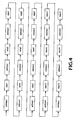
- Fig. 4 shows a serial of commands according to the present invention.
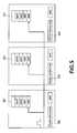
- Fig. 5 is schematic diagram showing queued data in axis drive.
- the self-synchronous AC servo system 30 adopts multiple axes control.
- the self-synchronous AC servo system 30 comprises a transmission line 32, a computer 34 coupled to the transmission line 32, a master axis drive 36 coupled to the transmission line 32, a master axis motor 38 coupled to the master axis drive 36, a plurality of slave axis drives 42 coupled to the transmission line 32, and a plurality of slave axis motors 40 coupled to the slave axis drives 42.
- the number of the master axis motor 38 and the slave axis motors 40 is not limited to that shown in Fig. 3.
- the master axis motor 38 and the slave axis motors 40 are AC servo motors.
- the computer 34 issues command to the master axis drive 36 and the slave axis drives 42 through the transmission line 32.
- the first command includes address 1 and data 1; the second command includes address 2 and data 2; the third command includes address 3 and data 3; the forth command includes address 1 and data 4; the fifth command includes address 2 and data 5; the sixth command includes address 3 and data 6 ...etc, where the addresses 1, 2 and 3 are corresponding to the master axis drive 36 and the slave axis drives 42, 42.
- the master axis drive 36 and the slave axis drives 42 send interrupt requests to the computer 34 through the transmission line 32 after receiving commands.
- the master axis drive 36 and the slave axis drives 42 will judge whether the command is for itself by corresponding interrupt request.
- the master axis drive 36 and the slave axis drives 42 store command of the computer 32 in queues. According to the synchronous timing clocks for the master axis drive 36 and the slave axis drives 42, the master axis drive 36 and the slave axis drives 42 send commands stored in queues to drive the master axis motor 38 and the slave axis motors 40 synchronously.
- the master axis drive 36 includes a buffer 361 receiving command (in the form shown in Fig. 4) of the computer 34 through the transmission line 32.
- the command includes address information.
- address 1 indicates the master axis drive 36 and the data after the address 1 is the data to be sent to the master axis drive 36 (namely the data 1, data 4 etc. in Fig. 4).
- An error detector 362 detects whether the data in the command received by the buffer is correct and complete.
- a queue storage unit 363 stores the data in queue, wherein the data is judged to be correct and complete by the error detector 362.
- a reading and transmitting unit 364 reads the stored data of the queue storage unit 363 and sends the data to a position command area 365.
- the reading and transmitting unit 364 reads data in the queue storage unit 363 and sends data to the position command area 365 according to synchronous clocks of the synchronous operation timing device 366, which is synchronous with the reading and transmitting unit 424 of the slave axis drive 42.
- the reading and transmitting unit 364 of the master axis drive 36 reads data 1 in the queue storage unit 363 and sends the data 1 to the position command area 365.
- the reading and transmitting unit 424, 424 of the first and the second slave axis drive 42 read data 2 and data 3 in the queue storage unit 423 and then send the data 2 and data 3 to the position command area 425, 425 of the second slave axis drive 42.
- the master axis motor 38 is driven according to the data received by the position command area 365.
- the slave axis drive 42 includes a buffer 421 to receive command sent from the computer 34 and having format shown in Fig. 4 through the transmission line 32.
- the command includes address information.
- the addresses 2 and 3 indicate the first and the second slave axis drives 42 and 42.
- the data after the addresses 2 and 3 indicate the data to be sent to the first and the second slave axis drives 42 and 42 (namely, the data 2, data 3, data 4, data 5, data 6 ... in Fig. 4).
- An error detector 422 detects whether the data in the command received by the buffer is correct and complete.
- the error detector 422 detects data in synchronism with the timing clock provided by the synchronous reception timing unit 427 and in synchronism with the slave axis drive 42.
- the reading and transmitting unit 424 works according to the timing clock of the synchronous operation timing device 366 of the master axis drive 36 and in synchronism with the reading and transmitting unit 364 of the master axis drive 36.
- the reading and transmitting unit 424 read the data stored in the queue storage unit 423 and then send the data to the position command area 425.
- the reading and transmitting unit 424, 424 of the first and the second slave axis drive 42, 42 read the data 2 and data 3 in the queue storage unit 423, 423 and then send the data 2 and data 3 to the position command area 425, 425.
- the reading and transmitting unit 364 of the master axis drive 36 reads the data 1 in the queue storage unit 363 and then sends the data 1 to the position command area 365.
- the slave axis motor 42 is driven according to the data received by the position command area 425.
- each axis drive can be automatically synchronized without using the synchronous command of the computer.
- the error tolerance for high-speed serial communication is enhanced by queued data and the automatic synchronism.
- the computer 34 sends a series of commands such that each axis drive 36, 42 will inform the computer 34 to stop sending command when the data in the queue storage unit 363, 423 is full.
- the axis drive 36, 42 will automatically operate the data sent from the queue storage unit 363, 423 according to the timing clock sent from the synchronous operation timing unit 366.
- the axis drive 36, 42 will ask the computer 34 to send command until the queue storage unit 363, 423 has full data.
- the frequency of the timing clock of the synchronous operation timing unit 366 is reduced if the remaining data in the queue storage unit 363, 423 reaches a predetermined amount. Therefore, the reading speed and the sending speed of the reading and transmitting unit 364, 424 is reduced.
- the axis motor has slow trace, but the path is not changed. Therefore, the problem of stop operation of the axis motor 38, 40 due to over low data rate in the queue storage unit 363, 423 can be solved when the error rate of the high speed serial communicating is high.
- the present invention has the advantage of error tolerance for high speed serial communication.
- Each axis drive has individual synchronism such that the high speed serial communication does not need synchronization protocol.
- the wiring and the cost can be saved.
Landscapes
- Engineering & Computer Science (AREA)
- Physics & Mathematics (AREA)
- General Physics & Mathematics (AREA)
- Automation & Control Theory (AREA)
- Manufacturing & Machinery (AREA)
- Computer Hardware Design (AREA)
- Microelectronics & Electronic Packaging (AREA)
- Human Computer Interaction (AREA)
- General Engineering & Computer Science (AREA)
- Quality & Reliability (AREA)
- Numerical Control (AREA)
Abstract
Description
- The present invention relates to an AC servo system, especially to a self-synchronous AC servo system for high-speed serial communication,
- The current multiple axes control architecture is centralized control. The multiple axes control architecture with centralized control includes an upper controller to control servo drive for linear/circular multiple axes interpolation by following wiring or high-speed communication.
- Fig. 1 shows a schematic diagram of a prior art centralized control system for multiple axes control. The command and I/
O 14 control of the multiple axes interpolation for theservo drive 12 is dealt by theupper controller 16. The signal from each axis is connected to theservo drive 12 through conventional wiring. However, the above scheme has following advantages: - 1. High cost: The performance of the
upper controller 16 is demanding for more axes. The CPU (now shown) of theupper controller 16 is also requested with higher grade. - 2. Limited axes number: The axes number of the
servo drive 12 is limited by CPU grade and hardware channel number. - 3. Complicated wiring: There are complicated wiring of A/D, D/A, command pulse, feedback pulse, digital I/O signals between
upper controller 16 andservo drive 12. - 4. Insufficient resolution: The command signal is limited by physical signals such as A/D conversion resolution and pulse frequency.
- 5. Environment interference: The analog signal tends to be interfered in factory environment.
- 6. Maintenance problem: The wires are more complicated when the axes number of the
servo drive 12 is large. The inspection and maintenance are troublesome. - Fig. 2 shows the schematic diagram of a prior art control system for multiple axes control with high speed communication, where the wire between the
upper controller 16 andservo drive 12 in Fig. 1 is replaced by a highspeed communication network 18. The highspeed communication network 18 has simple wiring and can prevent interference and enhance resolution. Theservo drive 12 does not have interpolation ability for path commands such that theupper controller 16 needs to send intense interpolation commands (more than 1KHz) to each axis to achieve path denseness. However, the network is also used for sending feedback position, current and I/O status besides position and speed commands. The data throughput is high when the axes number is high and the status of each axis needs monitoring. The bandwidth of the highspeed communication network 18 needs at least 10MHz, which induces following results. - 1. Interference prone: High speed communication is more sensitive to noise and high-standard communication hardware such as optical fiber is needed in factory environment.
- 2. Insufficient synchronism: The serial command is difficult to transit to each axis in synchronism.
- The present invention is intended to provide self-synchronous AC servo system for high-speed serial communication, such that the high-speed serial communication does not need synchronization protocol. The wiring and the cost can be saved.
- Accordingly, the present invention provides a self-synchronous AC servo system for high-speed serial communication, the system used for multiple axes control and comprising: a transmission line; a computer coupled to the transmission line; a master axis drive coupled to the transmission line; a master axis motor coupled to the master axis drive; a plurality of slave axis drives coupled to the transmission line; and a plurality of slave axis motor coupled to the slave axis drives; wherein the computer sends command to the master axis drive and the slave axis drives through the transmission line, the master axis drive and the slave axis drives sending interrupt request to the computer after receiving command from the computer; wherein each drive judging whether or not the command is for itself; the drives storing a plurality of commands from the computer in queue; the drives driving the master axis drive and the slave axis drives in synchronism by the commands stored in queue according to a synchronous timing clock.
- Accordingly, the present invention provides a method for operating a self-synchronous AC servo system for high-speed serial communication, the method comprising: a computer sending command to a master axis drive and a plurality of slave axis drives through a transmission line; the master axis drive and the slave axis drives sending interrupt requests to the computer through the transmission line after receiving command; the drive judging whether the command is for itself by the interrupt request;
the drive stores a plurality of commands of computer in queue; and the drive controls the master axis drive and the slave axis drives by the commands stored in queue and according to a synchronous timing clock. - The features of the invention believed to be novel are set forth with particularity in the appended claims. The invention itself however may be best understood by reference to the following detailed description of the invention, which describes certain exemplary embodiments of the invention, taken in conjunction with the accompanying drawings in which:
- Fig. 1 shows a schematic diagram of a prior art centralized control system for multiple axes control.
- Fig. 2 shows the schematic diagram of a prior art control system for multiple axes control with high speed communication.
- Fig 3 shows a block diagram of the self-synchronous AC servo system for high-speed serial communication of the present invention.
- Fig. 4 shows a serial of commands according to the present invention.
- Fig. 5 is schematic diagram showing queued data in axis drive.
- Fig 3 shows a block diagram of the self-synchronous AC servo system for high-speed serial communication of the present invention. Fig. 4 shows a serial of commands according to the present invention. Fig. 5 is schematic diagram showing queued data in axis drive.
- As shown in Fig. 3, the self-synchronous
AC servo system 30 adopts multiple axes control. The self-synchronousAC servo system 30 comprises atransmission line 32, acomputer 34 coupled to thetransmission line 32, amaster axis drive 36 coupled to thetransmission line 32, amaster axis motor 38 coupled to themaster axis drive 36, a plurality ofslave axis drives 42 coupled to thetransmission line 32, and a plurality ofslave axis motors 40 coupled to theslave axis drives 42. It should be noted that the number of themaster axis motor 38 and theslave axis motors 40 is not limited to that shown in Fig. 3. Themaster axis motor 38 and theslave axis motors 40 are AC servo motors. - The
computer 34 issues command to themaster axis drive 36 and the slave axis drives 42 through thetransmission line 32. As shown in Fig. 4, the first command includes address 1 and data 1; the second command includes address 2 and data 2; the third command includes address 3 and data 3; the forth command includes address 1 and data 4; the fifth command includes address 2 and data 5; the sixth command includes address 3 and data 6 ...etc, where the addresses 1, 2 and 3 are corresponding to themaster axis drive 36 and theslave axis drives master axis drive 36 and the slave axis drives 42 send interrupt requests to thecomputer 34 through thetransmission line 32 after receiving commands. Themaster axis drive 36 and theslave axis drives 42 will judge whether the command is for itself by corresponding interrupt request. Themaster axis drive 36 and the slave axis drives 42 store command of thecomputer 32 in queues. According to the synchronous timing clocks for themaster axis drive 36 and theslave axis drives 42, themaster axis drive 36 and theslave axis drives 42 send commands stored in queues to drive themaster axis motor 38 and theslave axis motors 40 synchronously. - In Fig. 3, the
master axis drive 36 includes abuffer 361 receiving command (in the form shown in Fig. 4) of thecomputer 34 through thetransmission line 32. The command includes address information. In the preferred embodiment, address 1 indicates themaster axis drive 36 and the data after the address 1 is the data to be sent to the master axis drive 36 (namely the data 1, data 4 etc. in Fig. 4). Anerror detector 362 detects whether the data in the command received by the buffer is correct and complete. Aqueue storage unit 363 stores the data in queue, wherein the data is judged to be correct and complete by theerror detector 362. A reading and transmittingunit 364 reads the stored data of thequeue storage unit 363 and sends the data to aposition command area 365. The reading and transmittingunit 364 reads data in thequeue storage unit 363 and sends data to theposition command area 365 according to synchronous clocks of the synchronousoperation timing device 366, which is synchronous with the reading and transmittingunit 424 of theslave axis drive 42. - As shown in Fig. 5, according to the first period of the synchronous
operation timing device 366, the reading and transmittingunit 364 of themaster axis drive 36 reads data 1 in thequeue storage unit 363 and sends the data 1 to theposition command area 365. In the same cycle, the reading and transmittingunit slave axis drive 42 read data 2 and data 3 in thequeue storage unit 423 and then send the data 2 and data 3 to theposition command area slave axis drive 42. Themaster axis motor 38 is driven according to the data received by theposition command area 365. - The
slave axis drive 42 includes abuffer 421 to receive command sent from thecomputer 34 and having format shown in Fig. 4 through thetransmission line 32. The command includes address information. In this preferred embodiment, the addresses 2 and 3 indicate the first and the second slave axis drives 42 and 42. The data after the addresses 2 and 3 indicate the data to be sent to the first and the second slave axis drives 42 and 42 (namely, the data 2, data 3, data 4, data 5, data 6 ... in Fig. 4). Anerror detector 422 detects whether the data in the command received by the buffer is correct and complete. Theerror detector 422 detects data in synchronism with the timing clock provided by the synchronousreception timing unit 427 and in synchronism with theslave axis drive 42. - As shown in Fig. 5, the reading and transmitting
unit 424 works according to the timing clock of the synchronousoperation timing device 366 of themaster axis drive 36 and in synchronism with the reading and transmittingunit 364 of themaster axis drive 36. The reading and transmittingunit 424 read the data stored in thequeue storage unit 423 and then send the data to theposition command area 425. As shown in Fig. 5, according to the first clock of the synchronousoperation timing unit 366, the reading and transmittingunit slave axis drive queue storage unit position command area unit 364 of themaster axis drive 36 reads the data 1 in thequeue storage unit 363 and then sends the data 1 to theposition command area 365. Theslave axis motor 42 is driven according to the data received by theposition command area 425. - As can be seen from above description, the data in the queue storage unit of each axis drive is triggered according to the timing clock of the synchronous timing unit of the master axis drive to send to each position command area. Therefore, each axis drive can be automatically synchronized without using the synchronous command of the computer. The error tolerance for high-speed serial communication is enhanced by queued data and the automatic synchronism.
- The
computer 34 sends a series of commands such that eachaxis drive computer 34 to stop sending command when the data in thequeue storage unit axis drive queue storage unit operation timing unit 366. When the remaining data in thequeue storage unit axis drive computer 34 to send command until thequeue storage unit computer 34 sends command and thequeue storage unit operation timing unit 366 is reduced if the remaining data in thequeue storage unit unit axis motor queue storage unit - To sum up, the present invention has the advantage of error tolerance for high speed serial communication. Each axis drive has individual synchronism such that the high speed serial communication does not need synchronization protocol. The wiring and the cost can be saved.
- Although the present invention has been described with reference to the preferred embodiment thereof, it will be understood that the invention is not limited to the details thereof. Various substitutions and modifications have suggested in the foregoing description, and other will occur to those of ordinary skill in the art. Therefore, all such substitutions and modifications are intended to be embraced within the scope of the invention as defined in the appended claims.
Claims (8)
- A self-synchronous AC servo system for high-speed serial communication, the system used for multiple axes control and comprising:a transmission line (32);a computer (34) coupled to the transmission line (32);a master axis drive (36) coupled to the transmission line (32);a master axis motor (38) coupled to the master axis drive (36);a plurality of slave axis drives (42) coupled to the transmission line (32); anda plurality of slave axis motor (40) coupled to the slave axis drives (42);wherein the computer (34) sends command to the master axis drive (36) and the slave axis drives (42) through the transmission line (42), the master axis drive (36) and the slave axis drives (42) sending interrupt request to the computer (34) after receiving command from the computer (34),wherein each drive judging whether or not the command is for itself;the drives storing a plurality of commands from the computer (34) in queue;the drives driving the master axis motor (38) and the slave axis motors (40) in synchronism by the commands stored in queue according to a synchronous timing clock.
- The system as in claim 1, wherein
the master axis drive (36) comprises
a buffer (361) receiving command from the computer (34) through the transmission line (32);
means for detecting error (362), which detects whether the data received by the buffer (361) is correct and complete;
means for queuing (363), which stores the data judged to be correct and complete by the means for detecting error (362) in queue;
means for reading and transmitting (364), which reads the data stored in queue by the means for queuing (363) and then transmitting the data;
means for synchronous operation timing clock (366), which generates a synchronous operation timing clock, wherein the means for reading and transmitting (364) transmits the data according to the synchronous operation timing clock; and
a position command area (365), wherein the means for reading and transmitting (364) transmits data to the position command area (365) and the position command area (365) drives the master axis motor (38) according to the data of the position command area (365);
the slave axis drive (42) comprising:a buffer (421) receiving command from the computer (34) through the transmission line (32);means for detecting error (422), which detects whether the data received by the buffer (421) is correct and complete;means for synchronous reception timing clock (427), which generates a synchronous reception timing clock, wherein the means for detecting error (422) detects the data according to the synchronous reception timing clock;means for queuing (423), which stores the data judged to be correct and complete by the means for detecting error (422) in queue;means for reading and transmitting (424), which reads the data stored in queue by the means for queuing according to the synchronous operation timing clock and then transmitting the data;a position command area (425), wherein the means for reading and transmitting (424) transmits data to the position command area (425) and the position command area (425) drives the slave axis motor (40) according to the data of the position command area. - The system as in claim 1, wherein the computer (34) sends a serial of command to fill the means for queuing (363, 423); the drive (36, 42) informing the computer to stop sending command when the means for queuing (363, 423) is full; the drive (36, 42) asks the computer (34) to resend command when a remaining data amount in the means for queuing (363, 423) reaches a predetermined amount; the means for synchronous operation timing clock (366) slows the synchronous operation timing clock when a remaining data amount in the means for queuing (363) reaches a predetermined minimum, whereby operation speed of the means for reading and transmitting (364) is slower.
- The system as in claim 1, wherein the master axis motor (38) and the slave axis motor (40) are AC servo motors.
- A method for operating a self-synchronous AC servo system for high-speed serial communication, comprising:a computer (34) sending command to a master axis drive (36) and a plurality of slave axis drives (42) through a transmission line (32);the master axis drive (36) and the slave axis drives (42) sending interrupt requests to the computer (34) through the transmission line (32) after receiving command;the drive (36, 42) judging whether the command is for itself by the interrupt request;the drive (36, 42) storing a plurality of commands of computer in queue; andthe drive (36, 42) controls the master axis drive (36) and the slave axis drives (42) by the commands stored in queue and according to a synchronous operation timing clock.
- The method as in claim 5, further comprising:a buffer (361) of the master axis drive (36) and a buffer (421) of the slave axis drive (42) receiving command of the computer (34) through the transmission line (32);using means for detecting error (362) of the master axis drive (36) to detect whether the data received by the buffer (361) is correct and complete;according to a synchronous reception clock, using means for detecting error (422) of the slave axis drive (42) to detect whether the data received by the buffer (421) of the slave axis drive (42) is correct and complete;using means for queuing (363, 423) of the master axis drive (36) and the slave axis drive (42) to store the data judged to be correct and complete by the means for detecting error (362, 422) in queueaccording to the synchronous reception clock, using means for reading and transmitting (364, 424) of the master axis drive (36) and the slave axis drive (42) to read the data stored in queue by the means for queuing (363, 423) and then transmit the data to position command area (365, 425) of the master axis drive (36) and the slave axis drive (42); anddriving the master axis motor (38) and the slave axis motor (40) according to the data sent to the position command area (365, 425) of the master axis drive (36) and the slave axis drive (42).
- The method as in claim 5, further comprising
the computer (34) sending a serial of command to fill the means for queuing (363, 423); the drive (36 ,42) informing the computer (34) to stop sending command when the means for queuing (363, 423) is full;
the drive (36 ,42) asking the computer (34) to resend command when a remaining data amount in the means for queuing (363, 423) reaches a predetermined amount;
the means for synchronous operation timing clock (366) slowing the synchronous operation timing clock when a remaining data amount in the means for queuing (363) reaches a predetermined minimum. - The method as in claim 5, wherein the master axis motor (38) and the slave axis motor (40) are AC servo motors.
Priority Applications (2)
| Application Number | Priority Date | Filing Date | Title |
|---|---|---|---|
| DE602006000461T DE602006000461T2 (en) | 2006-03-20 | 2006-03-20 | Autosynchronous AC servo system for high-speed serial communication |
| EP06005635A EP1837727B1 (en) | 2006-03-20 | 2006-03-20 | Self-synchronous AC servo system for high-speed serial communication |
Applications Claiming Priority (1)
| Application Number | Priority Date | Filing Date | Title |
|---|---|---|---|
| EP06005635A EP1837727B1 (en) | 2006-03-20 | 2006-03-20 | Self-synchronous AC servo system for high-speed serial communication |
Publications (2)
| Publication Number | Publication Date |
|---|---|
| EP1837727A1 true EP1837727A1 (en) | 2007-09-26 |
| EP1837727B1 EP1837727B1 (en) | 2008-01-16 |
Family
ID=36283931
Family Applications (1)
| Application Number | Title | Priority Date | Filing Date |
|---|---|---|---|
| EP06005635A Expired - Lifetime EP1837727B1 (en) | 2006-03-20 | 2006-03-20 | Self-synchronous AC servo system for high-speed serial communication |
Country Status (2)
| Country | Link |
|---|---|
| EP (1) | EP1837727B1 (en) |
| DE (1) | DE602006000461T2 (en) |
Cited By (3)
| Publication number | Priority date | Publication date | Assignee | Title |
|---|---|---|---|---|
| JP2018525754A (en) * | 2015-08-31 | 2018-09-06 | マーポス、ソチエタ、ペル、アツィオーニMarposs S.P.A. | Data processing and transmission system and method |
| US11300946B2 (en) | 2018-04-26 | 2022-04-12 | Siemens Aktiengesellschaft | Control component and method for determining an adapted master value of a master axis |
| WO2025062474A1 (en) * | 2023-09-19 | 2025-03-27 | ファナック株式会社 | Numerical control device and computer-readable storage medium |
Families Citing this family (1)
| Publication number | Priority date | Publication date | Assignee | Title |
|---|---|---|---|---|
| CN109960220A (en) * | 2017-12-26 | 2019-07-02 | 宁波菲仕电机技术有限公司 | For building the servo-control system and its control method of brick making machine vibration table |
Citations (4)
| Publication number | Priority date | Publication date | Assignee | Title |
|---|---|---|---|---|
| EP0371143A1 (en) * | 1988-05-31 | 1990-06-06 | Fanuc Ltd. | Method of numerical control |
| DE19539519A1 (en) * | 1994-10-25 | 1996-05-02 | Mitsubishi Electric Corp | Drive control command unit for industrial machines |
| DE10312379A1 (en) * | 2002-04-04 | 2003-10-16 | Heidelberger Druckmasch Ag | Master-slave drive combinations synchronizing method for printing presses, involves prescribing master-synchronous operating values determined using synchronization function to each operating time of respective slave drive |
| DE10345231A1 (en) * | 2002-10-07 | 2004-06-24 | Siemens Ag | Coordination of at least one slave control unit with master control unit for drive control system involves synchronizing control units to bus system working clock independently of each other |
-
2006
- 2006-03-20 EP EP06005635A patent/EP1837727B1/en not_active Expired - Lifetime
- 2006-03-20 DE DE602006000461T patent/DE602006000461T2/en not_active Expired - Lifetime
Patent Citations (4)
| Publication number | Priority date | Publication date | Assignee | Title |
|---|---|---|---|---|
| EP0371143A1 (en) * | 1988-05-31 | 1990-06-06 | Fanuc Ltd. | Method of numerical control |
| DE19539519A1 (en) * | 1994-10-25 | 1996-05-02 | Mitsubishi Electric Corp | Drive control command unit for industrial machines |
| DE10312379A1 (en) * | 2002-04-04 | 2003-10-16 | Heidelberger Druckmasch Ag | Master-slave drive combinations synchronizing method for printing presses, involves prescribing master-synchronous operating values determined using synchronization function to each operating time of respective slave drive |
| DE10345231A1 (en) * | 2002-10-07 | 2004-06-24 | Siemens Ag | Coordination of at least one slave control unit with master control unit for drive control system involves synchronizing control units to bus system working clock independently of each other |
Cited By (5)
| Publication number | Priority date | Publication date | Assignee | Title |
|---|---|---|---|---|
| JP2018525754A (en) * | 2015-08-31 | 2018-09-06 | マーポス、ソチエタ、ペル、アツィオーニMarposs S.P.A. | Data processing and transmission system and method |
| US10942505B2 (en) | 2015-08-31 | 2021-03-09 | Marposs Societa' Per Azioni | Data processing and transmission system and method |
| US11300946B2 (en) | 2018-04-26 | 2022-04-12 | Siemens Aktiengesellschaft | Control component and method for determining an adapted master value of a master axis |
| EP3561621B1 (en) * | 2018-04-26 | 2023-01-04 | Siemens Aktiengesellschaft | Determination of an adapted leading value |
| WO2025062474A1 (en) * | 2023-09-19 | 2025-03-27 | ファナック株式会社 | Numerical control device and computer-readable storage medium |
Also Published As
| Publication number | Publication date |
|---|---|
| DE602006000461D1 (en) | 2008-03-06 |
| DE602006000461T2 (en) | 2009-01-15 |
| EP1837727B1 (en) | 2008-01-16 |
Similar Documents
| Publication | Publication Date | Title |
|---|---|---|
| JP3566304B2 (en) | Bus control device and bus control system | |
| US5553095A (en) | Method and apparatus for exchanging different classes of data during different time intervals | |
| EP0622712B1 (en) | Communication network with time coordinated station activity | |
| EP0622711B1 (en) | Digital communication network data transmission method and apparatus | |
| JPWO1998035296A1 (en) | Bus control device and bus control system | |
| EP3264685B1 (en) | Data transmitting and receiving method, data transmitting and receiving system, master device, and slave device | |
| JP2012142007A (en) | Method and device for performing serial data transmission between position measurement system and processing unit | |
| US7180261B1 (en) | Self-synchronous AC servo system for high-speed serial communication | |
| JP2001069159A (en) | Method for applying backup link active schedule and system for controlling communication while using link active schedule | |
| CN103765760B (en) | The control method of one-piece type servo-drive system, electric motor system and motor | |
| CN105144131A (en) | Power stack control systems | |
| CN112910593A (en) | Synchronous control system and method applied to servo motor driver | |
| EP1837727B1 (en) | Self-synchronous AC servo system for high-speed serial communication | |
| CN103107862B (en) | Logical device and MDIO data transmission method for uplink thereof | |
| JP2006520118A (en) | Method, interface, and network for periodically transmitting Ethernet messages | |
| US7177280B2 (en) | Data transfer processing apparatus, data transfer method, and data transfer program | |
| JP4942545B2 (en) | Synchronization method for bidirectional transmission of data and system using the same | |
| JP4642683B2 (en) | Automatic synchronous AC servo system for high-speed serial communication and its operating method | |
| CN117681229A (en) | Robot control system and robot | |
| CN117560756A (en) | Data transmission synchronization method and device, chip, electronic equipment and storage medium | |
| CN100501618C (en) | Self-synchronizing AC servo system matched with high-speed serial communication | |
| JP2000099155A (en) | Servo driver control method | |
| JP2017085831A (en) | Motor controller | |
| EP2929646A1 (en) | Motion control system using asynchronous communication and controller and method thereof | |
| JPH10233792A (en) | Polling system/method |
Legal Events
| Date | Code | Title | Description |
|---|---|---|---|
| GRAC | Information related to communication of intention to grant a patent modified |
Free format text: ORIGINAL CODE: EPIDOSCIGR1 |
|
| GRAP | Despatch of communication of intention to grant a patent |
Free format text: ORIGINAL CODE: EPIDOSNIGR1 |
|
| PUAI | Public reference made under article 153(3) epc to a published international application that has entered the european phase |
Free format text: ORIGINAL CODE: 0009012 |
|
| 17P | Request for examination filed |
Effective date: 20070122 |
|
| AK | Designated contracting states |
Kind code of ref document: A1 Designated state(s): AT BE BG CH CY CZ DE DK EE ES FI FR GB GR HU IE IS IT LI LT LU LV MC NL PL PT RO SE SI SK TR |
|
| AX | Request for extension of the european patent |
Extension state: AL BA HR MK YU |
|
| GRAS | Grant fee paid |
Free format text: ORIGINAL CODE: EPIDOSNIGR3 |
|
| GRAA | (expected) grant |
Free format text: ORIGINAL CODE: 0009210 |
|
| AK | Designated contracting states |
Kind code of ref document: B1 Designated state(s): DE |
|
| REF | Corresponds to: |
Ref document number: 602006000461 Country of ref document: DE Date of ref document: 20080306 Kind code of ref document: P |
|
| AKX | Designation fees paid |
Designated state(s): DE |
|
| PLBE | No opposition filed within time limit |
Free format text: ORIGINAL CODE: 0009261 |
|
| STAA | Information on the status of an ep patent application or granted ep patent |
Free format text: STATUS: NO OPPOSITION FILED WITHIN TIME LIMIT |
|
| 26N | No opposition filed |
Effective date: 20081017 |
|
| PGFP | Annual fee paid to national office [announced via postgrant information from national office to epo] |
Ref country code: DE Payment date: 20250327 Year of fee payment: 20 |
|
| REG | Reference to a national code |
Ref country code: DE Ref legal event code: R071 Ref document number: 602006000461 Country of ref document: DE |