EP1837691A1 - Fisheye converter for a telephoto zoom lens - Google Patents
Fisheye converter for a telephoto zoom lens Download PDFInfo
- Publication number
- EP1837691A1 EP1837691A1 EP07103945A EP07103945A EP1837691A1 EP 1837691 A1 EP1837691 A1 EP 1837691A1 EP 07103945 A EP07103945 A EP 07103945A EP 07103945 A EP07103945 A EP 07103945A EP 1837691 A1 EP1837691 A1 EP 1837691A1
- Authority
- EP
- European Patent Office
- Prior art keywords
- lens
- aspherical
- image
- fisheye
- optical
- Prior art date
- Legal status (The legal status is an assumption and is not a legal conclusion. Google has not performed a legal analysis and makes no representation as to the accuracy of the status listed.)
- Granted
Links
- 230000003287 optical effect Effects 0.000 claims description 47
- 230000002093 peripheral effect Effects 0.000 claims description 3
- 230000007423 decrease Effects 0.000 claims 1
- 230000000694 effects Effects 0.000 abstract description 17
- 239000003638 chemical reducing agent Substances 0.000 abstract 1
- 239000003623 enhancer Substances 0.000 abstract 1
- 230000004075 alteration Effects 0.000 description 18
- 201000009310 astigmatism Diseases 0.000 description 14
- 238000003384 imaging method Methods 0.000 description 2
- 102220414581 c.33A>G Human genes 0.000 description 1
- 102220388537 c.42C>T Human genes 0.000 description 1
- 238000006243 chemical reaction Methods 0.000 description 1
- 239000000470 constituent Substances 0.000 description 1
- 230000003247 decreasing effect Effects 0.000 description 1
- 230000006866 deterioration Effects 0.000 description 1
- 238000010586 diagram Methods 0.000 description 1
- 239000011521 glass Substances 0.000 description 1
- 238000012986 modification Methods 0.000 description 1
- 230000004048 modification Effects 0.000 description 1
- 102220305863 rs1015663503 Human genes 0.000 description 1
- 102220205468 rs1057523833 Human genes 0.000 description 1
- 102220214374 rs1060504419 Human genes 0.000 description 1
- 102220228145 rs1064794513 Human genes 0.000 description 1
- 102220184965 rs117987946 Human genes 0.000 description 1
- 102220274895 rs1260697914 Human genes 0.000 description 1
- 102220297462 rs1264640823 Human genes 0.000 description 1
- 102220279556 rs1305090923 Human genes 0.000 description 1
- 102220264750 rs1305455942 Human genes 0.000 description 1
- 102220053926 rs137962152 Human genes 0.000 description 1
- 102220123988 rs138203039 Human genes 0.000 description 1
- 102220132826 rs139286202 Human genes 0.000 description 1
- 102220286063 rs1405786437 Human genes 0.000 description 1
- 102220114365 rs141538225 Human genes 0.000 description 1
- 102220208315 rs141965142 Human genes 0.000 description 1
- 102220265263 rs1449870708 Human genes 0.000 description 1
- 102220131033 rs145667920 Human genes 0.000 description 1
- 102220264498 rs1457262106 Human genes 0.000 description 1
- 102220017114 rs150867836 Human genes 0.000 description 1
- 102220067506 rs150937126 Human genes 0.000 description 1
- 102220280436 rs1555280114 Human genes 0.000 description 1
- 102220281519 rs1555462089 Human genes 0.000 description 1
- 102220270437 rs1555462102 Human genes 0.000 description 1
- 102220272282 rs1555570413 Human genes 0.000 description 1
- 102220172465 rs1893316 Human genes 0.000 description 1
- 102220008663 rs193922450 Human genes 0.000 description 1
- 102220126604 rs199625892 Human genes 0.000 description 1
- 102220053946 rs199631710 Human genes 0.000 description 1
- 102220101549 rs199890548 Human genes 0.000 description 1
- 102220076495 rs200649587 Human genes 0.000 description 1
- 102220148773 rs201411330 Human genes 0.000 description 1
- 102220033625 rs281865531 Human genes 0.000 description 1
- 102220290654 rs34058684 Human genes 0.000 description 1
- 102220204968 rs371017342 Human genes 0.000 description 1
- 102220112179 rs3743602 Human genes 0.000 description 1
- 102220205150 rs376527838 Human genes 0.000 description 1
- 102220024172 rs397515479 Human genes 0.000 description 1
- 102220012898 rs397516346 Human genes 0.000 description 1
- 102220014026 rs397517292 Human genes 0.000 description 1
- 102220029525 rs398123572 Human genes 0.000 description 1
- 102220207304 rs45572434 Human genes 0.000 description 1
- 102220118806 rs4876870 Human genes 0.000 description 1
- 102220095228 rs540871544 Human genes 0.000 description 1
- 102220060030 rs55861249 Human genes 0.000 description 1
- 102220042631 rs587780925 Human genes 0.000 description 1
- 102220032634 rs63750742 Human genes 0.000 description 1
- 102220039198 rs7243081 Human genes 0.000 description 1
- 102220201386 rs752794296 Human genes 0.000 description 1
- 102220037375 rs75383960 Human genes 0.000 description 1
- 102220263040 rs756923555 Human genes 0.000 description 1
- 102220176144 rs759794906 Human genes 0.000 description 1
- 102220201111 rs761498953 Human genes 0.000 description 1
- 102220249016 rs767770776 Human genes 0.000 description 1
- 102220218156 rs769282604 Human genes 0.000 description 1
- 102220062285 rs771765869 Human genes 0.000 description 1
- 102220271410 rs773045737 Human genes 0.000 description 1
- 102220065682 rs77311724 Human genes 0.000 description 1
- 102220095230 rs776810546 Human genes 0.000 description 1
- 102220207965 rs778468876 Human genes 0.000 description 1
- 102220094030 rs778803692 Human genes 0.000 description 1
- 102220059961 rs786201335 Human genes 0.000 description 1
- 102220058910 rs786201402 Human genes 0.000 description 1
- 102220058919 rs786202334 Human genes 0.000 description 1
- 102220060027 rs786203926 Human genes 0.000 description 1
- 102220095236 rs876658436 Human genes 0.000 description 1
- 102220095348 rs876659304 Human genes 0.000 description 1
- 102220099820 rs878853791 Human genes 0.000 description 1
- 102220152620 rs886060753 Human genes 0.000 description 1
- 102220151991 rs886061744 Human genes 0.000 description 1
- 102220158315 rs886063624 Human genes 0.000 description 1
- 238000004904 shortening Methods 0.000 description 1
Images




Classifications
-
- G—PHYSICS
- G02—OPTICS
- G02B—OPTICAL ELEMENTS, SYSTEMS OR APPARATUS
- G02B15/00—Optical objectives with means for varying the magnification
- G02B15/02—Optical objectives with means for varying the magnification by changing, adding, or subtracting a part of the objective, e.g. convertible objective
- G02B15/10—Optical objectives with means for varying the magnification by changing, adding, or subtracting a part of the objective, e.g. convertible objective by adding a part, e.g. close-up attachment
-
- G—PHYSICS
- G02—OPTICS
- G02B—OPTICAL ELEMENTS, SYSTEMS OR APPARATUS
- G02B13/00—Optical objectives specially designed for the purposes specified below
- G02B13/06—Panoramic objectives; So-called "sky lenses" including panoramic objectives having reflecting surfaces
-
- G—PHYSICS
- G02—OPTICS
- G02B—OPTICAL ELEMENTS, SYSTEMS OR APPARATUS
- G02B15/00—Optical objectives with means for varying the magnification
- G02B15/14—Optical objectives with means for varying the magnification by axial movement of one or more lenses or groups of lenses relative to the image plane for continuously varying the equivalent focal length of the objective
- G02B15/144—Optical objectives with means for varying the magnification by axial movement of one or more lenses or groups of lenses relative to the image plane for continuously varying the equivalent focal length of the objective having four groups only
- G02B15/1441—Optical objectives with means for varying the magnification by axial movement of one or more lenses or groups of lenses relative to the image plane for continuously varying the equivalent focal length of the objective having four groups only the first group being positive
- G02B15/144109—Optical objectives with means for varying the magnification by axial movement of one or more lenses or groups of lenses relative to the image plane for continuously varying the equivalent focal length of the objective having four groups only the first group being positive arranged +--+
-
- G—PHYSICS
- G02—OPTICS
- G02B—OPTICAL ELEMENTS, SYSTEMS OR APPARATUS
- G02B15/00—Optical objectives with means for varying the magnification
- G02B15/14—Optical objectives with means for varying the magnification by axial movement of one or more lenses or groups of lenses relative to the image plane for continuously varying the equivalent focal length of the objective
- G02B15/16—Optical objectives with means for varying the magnification by axial movement of one or more lenses or groups of lenses relative to the image plane for continuously varying the equivalent focal length of the objective with interdependent non-linearly related movements between one lens or lens group, and another lens or lens group
- G02B15/163—Optical objectives with means for varying the magnification by axial movement of one or more lenses or groups of lenses relative to the image plane for continuously varying the equivalent focal length of the objective with interdependent non-linearly related movements between one lens or lens group, and another lens or lens group having a first movable lens or lens group and a second movable lens or lens group, both in front of a fixed lens or lens group
- G02B15/167—Optical objectives with means for varying the magnification by axial movement of one or more lenses or groups of lenses relative to the image plane for continuously varying the equivalent focal length of the objective with interdependent non-linearly related movements between one lens or lens group, and another lens or lens group having a first movable lens or lens group and a second movable lens or lens group, both in front of a fixed lens or lens group having an additional fixed front lens or group of lenses
- G02B15/17—Optical objectives with means for varying the magnification by axial movement of one or more lenses or groups of lenses relative to the image plane for continuously varying the equivalent focal length of the objective with interdependent non-linearly related movements between one lens or lens group, and another lens or lens group having a first movable lens or lens group and a second movable lens or lens group, both in front of a fixed lens or lens group having an additional fixed front lens or group of lenses arranged +--
Definitions
- the present invention relates to a fisheye attachment to be attached to the object side of a shooting lens of an image-pickup apparatus, such as a still camera or a video camera, to give a fisheye effect.
- the fisheye attachment according to the present invention is an optical accessory to be detachably attached to a shooting lens to change optical characteristics of the lens.
- an optical accessory such as a converter or an attachment is attached to the object side of a shooting lens in the wide angle end state to produce a large negative distortion as discussed in, for example, Japanese Patent Laid-Open No. H11-305119 .
- fisheye attachments are designed in such a way that a large negative distortion that satisfies the following condition in terms of the image height y, the beam incidence angle ⁇ and the focal length f of the lens is generated.
- y / 2 ⁇ f sin ⁇ / 2
- the fisheye attachment is generally composed of a single negative lens, which cannot achieve the desired aberration correction. In particular, satisfactory correction of astigmatism and field curvature cannot be achieved.
- An object of the present invention is to provide a fisheye attachment having excellent optical performance by correcting aberrations, in particular astigmatism and field curvature.
- an optical accessory according to claim 1.
- the following conditions are satisfied: 0.8 ⁇ 10 - 4 ⁇ ⁇ ⁇ 7 / fe ⁇ 2.0 ⁇ 10 - 2 , 0.3 ⁇ ⁇ ⁇ 4 / ⁇ ⁇ 7 ⁇ 0.65 , and 0.4 ⁇ ⁇ ⁇ 9 / ⁇ ⁇ 7 ⁇ 1.0 , where fe represents the focal length of the lens FE, and ⁇ 9, ⁇ 7 and ⁇ 4 respectively represent the aspherical amounts at the image heights of 90%, 70% and 40% of the effective diameter of the lens FE having the aspherical surface, the aspherical amount is defined by a distance between the aspherical surface of the aspherical lens FE and a spherical surface along the optical axis direction, where the spherical surface has a center of curvature radius on the optical axis and contains three points: a vertex of the aspherical lens FE; and both ends of the maximum effective diameter of the aspherical lens
- r1 represents the curvature radius of the object side surface of the lens FE
- r2 represents the curvature radius of the image side surface of the lens FE
- the curvature radius of the aspherical lens FE is defined by a curvature radius of a spherical surface that has a center of curvature radius on the optical axis and contains three points: a vertex of the aspherical lens FE; and both ends of the maximum effective diameter of the aspherical lens FE.
- a shooting lens on which the optical accessory set out in the forgoing is attached.
- an image-pickup apparatus comprising the optical accessory set out in the foregoing and a shooting lens on which the optical accessory is attached.
- FIG. 1 is a cross-sectional view of a lens according to a first embodiment at the wide-angle end.
- FIG. 2 is a cross-sectional view of a master lens at the wide-angle end.
- FIG. 3 shows aberrations of the master lens at the wide-angle end.
- FIG. 4 shows aberrations in the first embodiment at the wide-angle end.
- FIG. 5 is a cross-sectional view of a lens according to a second embodiment at the wide-angle end.
- FIG. 6 shows aberrations in the second embodiment at the wide-angle end.
- FIG. 7 is a cross-sectional view of a lens according to a third embodiment at the wide-angle end.
- FIG. 8 shows aberrations in the third embodiment at the wide-angle end.
- FIG. 9 is a cross-sectional view of a lens according to a fourth embodiment at the wide-angle end.
- FIG. 10 shows aberrations in the fourth embodiment at the wide-angle end.
- FIG. 11 is a cross-sectional view of a lens according to a fifth embodiment at the wide-angle end.
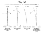
- FIG. 12 shows aberrations in the fifth embodiment at the wide-angle end.
- the described fisheye attachments have at least one lens having a negative refractive power.
- the negative lens is designed to have an aspherical surface, and the shape and the aspherical shape of the constituent lens(es) are appropriately determined, whereby excellent optical performance can be achieved with improved astigmatism and field curvature.
- a fisheye attachment is an optical accessory to be detachably attached to a shooting lens to change optical characteristics of the shooting lens.
- Fig. 1 is a cross-sectional view of a lens according to a first embodiment of the present invention in its wide-angle end state.
- a fisheye attachment lens FE is attached on the front side of a shooting lens as the master lens M.
- the master lens M has a front lens unit F functioning as the focusing unit, a variator V, a compensator C, a stop SP, a relay lens unit R and a color split prism or an optical filter P arranged in the mentioned order from front to rear.
- the front lens unit F has, as the first unit, a positive refractive power.
- the variator V has, as the second lens unit, a negative refractive power and is moved monotonously along the optical axis toward the image plane to change the magnification of the lens from the wide-angle end to the telephoto end.
- the compensator C has a negative refractive power and is adapted to be moved non-linearly along the optical axis to compensate image-plane variations caused upon changing the magnification.
- the variator V and the compensator C constitute a magnification-changing optical system.
- the relay-lens unit R has, as the fixed fourth unit, a positive refractive power.
- an optical element(s) P such as a color-split prism and/or an optical filter.
- the element P is illustrated as a glass block, in the case shown in Fig. 1.
- an image-pickup element such as a CCD sensor or a CMOS sensor.
- the image-pickup apparatus according to the present invention has the fisheye attachment FE, the master lens M and the image-pickup element.
- the image-pickup apparatus may be applied to a consumer still camera, a consumer video camera and a broadcast camera.
- the fisheye attachment FE is a negative lens having an image-side surface r2 that is convex toward the object side.
- the fisheye attachment FE has a function of shortening the focal length of the master lens M or enlarging the angle of field of the master lens M and generating a large negative distortion to give a fisheye effect. If the fisheye attachment FE has only spherical surfaces, astigmatism and field curvature are generated particularly at the image-side surface r2, which leads to deterioration in the optical performance in the peripheral area of the image.
- the image-side surface r2 is designed to be an aspherical surface with a negative refractive power decreasing toward its periphery, whereby the generation of astigmatism and field curvature is reduced and a flat image plane is achieved.
- the aspherical shape of the surface of the fisheye attachment FE may be designed to satisfy the following conditions (2) to (4), where fe represents the focal length of the fisheye attachment, and ⁇ 9, ⁇ 7 and ⁇ 4 respectively represent the aspherical amounts at the image heights of 90%, 70% and 40% of the effective diameter of the lens having that aspherical surface.
- fe represents the focal length of the fisheye attachment
- ⁇ 9, ⁇ 7 and ⁇ 4 respectively represent the aspherical amounts at the image heights of 90%, 70% and 40% of the effective diameter of the lens having that aspherical surface.
- the aspherical amount is defined by a distance between the aspherical surface of the aspherical lens FE and a spherical surface along the optical axis direction, where the spherical surface has a center of curvature radius on the optical axis and contains three points: a vertex of the aspherical lens FE; and both ends of the maximum effective diameter of the aspherical lens FE.
- r1 represents the curvature radius of the object side surface
- r2 represents the curvature radius of the image side surface under the assumption that the curvature radius of the aspherical lens FE is defined as a curvature radius of a spherical surface that has a center of curvature radius on the optical axis and contains three points: a vertex of the aspherical lens FE; and both ends of the maximum effective diameter of the aspherical lens FE.
- Condition (5) is added to make the value of the distortion generated by the fisheye attachment FE appropriate so as to give a suitable fisheye effect.
- the negative distortion becomes too high to give a suitable fisheye effect, or off-axial principal rays cannot be incident on the object side surface of the negative lens, which leads to eclipse.
- the negative distortion becomes too low to give a suitable fisheye effect, or the curvature of the image-side surface of the negative lens becomes so large that it becomes difficult to make such a lens.
- an imaging optical system for image-pickup is designed with a suppressed distortion.
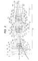
- Fig. 2 is a cross-sectional view of the master lens M, at the wide-angle end, to which the fisheye attachment FE is to be attached.
- R represents the curvature radius of each lens surface of the master lens M
- D represents the surface interval
- N represents the refractive index for the e-line
- ⁇ represents the Abbe number
- f represents the focal length of the entire system
- Fno represents the F number
- Bf represents the back focus
- 2 ⁇ represents the angle of field
- Y represents the image height.
- the angle of field 2 ⁇ is one in the case where distortion is not taken into account.
- the angle of field A can be calculated from the following equation using the value Di (%) of the distortion at the 100% image height in each aberration diagram.
- Di % of the distortion at the 100% image height in each aberration diagram.
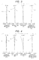
- Fig. 3 shows aberrations of the master lens M at the wide-angle end, where aberrations for the e-line are designated by “e”, aberrations for the g-line is designated by “g”, the meridional image plane is designated by “m”, and the sagittal image plane is designated by “s”.
- the fisheye attachment FE includes a lens having an aspherical surface r2 with a negative refractive power.
- the aspherical surface shape is expressed by the following equation (10), where the coordinate along the optical axis is represented by x, the coordinate along the direction perpendicular to the optical axis is represented by y, r represents a reference curvature radius, k represents the conic constant, and Cn represents the n-th order aspherical coefficient.
- Fig. 1 is a cross-sectional view of the lens in the state in which the above-described fisheye attachment FE according to the first embodiment is attached on the master lens M that is set to the wide-angle end.
- Fig. 4 shows aberrations in that state.
- n the refractive index for the e-line
- ⁇ the Abbe number.
- r represents the curvature radius of each lens surface in the fisheye attachment FE
- d represents the surface interval
- r* represents the curvature radius of the aspherical lens FE is defined as a curvature radius of a reference spherical surface that has a center of curvature radius on the optical axis and contains three points: a vertex of the aspherical lens; and both ends of the maximum effective diameter of the aspherical lens
- r** represents the local curvature radius of the aspherical surface.
- Fig. 5 is a cross-sectional view of the lens in the state in which a fisheye attachment FE according to a second embodiment is attached on the master lens M that is set to the wide-angle end.
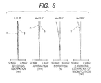
- Fig. 6 shows aberrations in that state.
- Fig. 7 is a cross-sectional view of the lens in the state in which a fisheye attachment FE according to a third embodiment is attached on the master lens M that is set to the wide-angle end.
- Fig. 8 shows aberrations in that state.
- Table 4 are presented various values on a third numerical embodiment of the fisheye attachment FE according to the third embodiment.
- Fig. 9 is a cross-sectional view of the lens in the state in which a fisheye attachment FE according to a fourth embodiment is attached on the master lens M that is set to the wide-angle end.
- Fig. 10 shows aberrations in that state.
- Table 5 are presented various values on a fourth numerical embodiment of the fisheye attachment FE according to the fourth embodiment.
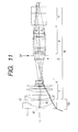
- Fig. 11 is a cross-sectional view of the lens in the state in which a fisheye attachment FE according to a fifth embodiment is attached on the master lens M that is set to the wide-angle end.
- Fig. 12 shows aberrations in that state.
- Table 7 shows the values associated with conditions (2), (3), (4) and (5) in numerical examples 1 to 5.
- the fisheye lens attachment FE includes a lens having an aspherical surface r2 with a negative refractive power that satisfies conditions (2) through (5). With these conditions, a large negative distortion is generated. Thus, a fisheye attachment FE that is satisfactorily corrected in terms of astigmatism and field curvature while having a suitable fisheye effect can be provided.
Landscapes
- Physics & Mathematics (AREA)
- General Physics & Mathematics (AREA)
- Optics & Photonics (AREA)
- Nonlinear Science (AREA)
- Lenses (AREA)
Abstract
The converter acts as a focal reducer, or field-of-view enhancer and provides a large negative distortion achieving the fisheye effect.
Description
- The present invention relates to a fisheye attachment to be attached to the object side of a shooting lens of an image-pickup apparatus, such as a still camera or a video camera, to give a fisheye effect. The fisheye attachment according to the present invention is an optical accessory to be detachably attached to a shooting lens to change optical characteristics of the lens.
- When a fisheye effect, or an effect of giving a distortion that is particularly conspicuous in the peripheral area of an image is desired in photo shooting, an optical accessory such as a converter or an attachment is attached to the object side of a shooting lens in the wide angle end state to produce a large negative distortion as discussed in, for example,
Japanese Patent Laid-Open No. H11-305119 - In recent years, with the spread of high definition broadcasting systems represented by the HDTV broadcasting, shooting lenses are required to have high optical performance. Accordingly, high performance optical accessories such as attachments to be attached to such shooting lenses are also demanded. To meet such a demand, it is necessary that aberrations of the optical accessories themselves be corrected satisfactorily.
- In particular, fisheye attachments are designed in such a way that a large negative distortion that satisfies the following condition in terms of the image height y, the beam incidence angle θ and the focal length f of the lens is generated.

- However, the fisheye attachment is generally composed of a single negative lens, which cannot achieve the desired aberration correction. In particular, satisfactory correction of astigmatism and field curvature cannot be achieved.
- An object of the present invention is to provide a fisheye attachment having excellent optical performance by correcting aberrations, in particular astigmatism and field curvature.
- According to a first aspect of the present invention there is provided an optical accessory according to claim 1.
- In some optical accessories embodying the invention, the following conditions are satisfied:


where fe represents the focal length of the lens FE, and Δ9, Δ7 and Δ4 respectively represent the aspherical amounts at the image heights of 90%, 70% and 40% of the effective diameter of the lens FE having the aspherical surface, the aspherical amount is defined by a distance between the aspherical surface of the aspherical lens FE and a spherical surface along the optical axis direction, where the spherical surface has a center of curvature radius on the optical axis and contains three points: a vertex of the aspherical lens FE; and both ends of the maximum effective diameter of the aspherical lens FE. - In other embodiments, the following conditions are satisfied:


where r1 represents the curvature radius of the object side surface of the lens FE and r2 represents the curvature radius of the image side surface of the lens FE, the curvature radius of the aspherical lens FE is defined by a curvature radius of a spherical surface that has a center of curvature radius on the optical axis and contains three points: a vertex of the aspherical lens FE; and both ends of the maximum effective diameter of the aspherical lens FE. - There may also be provided a shooting lens on which the optical accessory set out in the forgoing is attached.
- There may also be provided an image-pickup apparatus comprising the optical accessory set out in the foregoing and a shooting lens on which the optical accessory is attached.
- Further features of the present invention will become apparent from the following description of exemplary embodiments with reference to the attached drawings.
- FIG. 1 is a cross-sectional view of a lens according to a first embodiment at the wide-angle end.
- FIG. 2 is a cross-sectional view of a master lens at the wide-angle end.
- FIG. 3 shows aberrations of the master lens at the wide-angle end.
- FIG. 4 shows aberrations in the first embodiment at the wide-angle end.
- FIG. 5 is a cross-sectional view of a lens according to a second embodiment at the wide-angle end.
- FIG. 6 shows aberrations in the second embodiment at the wide-angle end.
- FIG. 7 is a cross-sectional view of a lens according to a third embodiment at the wide-angle end.
- FIG. 8 shows aberrations in the third embodiment at the wide-angle end.
- FIG. 9 is a cross-sectional view of a lens according to a fourth embodiment at the wide-angle end.
- FIG. 10 shows aberrations in the fourth embodiment at the wide-angle end.
- FIG. 11 is a cross-sectional view of a lens according to a fifth embodiment at the wide-angle end.
- FIG. 12 shows aberrations in the fifth embodiment at the wide-angle end.
- The described fisheye attachments have at least one lens having a negative refractive power. The negative lens is designed to have an aspherical surface, and the shape and the aspherical shape of the constituent lens(es) are appropriately determined, whereby excellent optical performance can be achieved with improved astigmatism and field curvature.
- A fisheye attachment is an optical accessory to be detachably attached to a shooting lens to change optical characteristics of the shooting lens.
- Further, the fisheye attachment of the present invention is an optical accessory which causes a large negative distortion satisfying the following equation,

where y represents an image height, θ represents incident angle of the light beam, and f represents focal length of the lens. Note that the image-pickup angle is not limited to 180 degrees. - (First Embodiment)
- Fig. 1 is a cross-sectional view of a lens according to a first embodiment of the present invention in its wide-angle end state. A fisheye attachment lens FE is attached on the front side of a shooting lens as the master lens M. The master lens M has a front lens unit F functioning as the focusing unit, a variator V, a compensator C, a stop SP, a relay lens unit R and a color split prism or an optical filter P arranged in the mentioned order from front to rear.
- The front lens unit F has, as the first unit, a positive refractive power. The variator V has, as the second lens unit, a negative refractive power and is moved monotonously along the optical axis toward the image plane to change the magnification of the lens from the wide-angle end to the telephoto end. The compensator C has a negative refractive power and is adapted to be moved non-linearly along the optical axis to compensate image-plane variations caused upon changing the magnification. The variator V and the compensator C constitute a magnification-changing optical system. The relay-lens unit R has, as the fixed fourth unit, a positive refractive power. There also is provided an optical element(s) P such as a color-split prism and/or an optical filter. The element P is illustrated as a glass block, in the case shown in Fig. 1. On the image side of the color-split prism or the optical filter is provided an image-pickup element such as a CCD sensor or a CMOS sensor. The image-pickup apparatus according to the present invention has the fisheye attachment FE, the master lens M and the image-pickup element. The image-pickup apparatus may be applied to a consumer still camera, a consumer video camera and a broadcast camera.
- The fisheye attachment FE is a negative lens having an image-side surface r2 that is convex toward the object side. The fisheye attachment FE has a function of shortening the focal length of the master lens M or enlarging the angle of field of the master lens M and generating a large negative distortion to give a fisheye effect. If the fisheye attachment FE has only spherical surfaces, astigmatism and field curvature are generated particularly at the image-side surface r2, which leads to deterioration in the optical performance in the peripheral area of the image. In view of this, in this embodiment, the image-side surface r2 is designed to be an aspherical surface with a negative refractive power decreasing toward its periphery, whereby the generation of astigmatism and field curvature is reduced and a flat image plane is achieved.
- More preferably, the aspherical shape of the surface of the fisheye attachment FE may be designed to satisfy the following conditions (2) to (4), where fe represents the focal length of the fisheye attachment, and Δ9, Δ7 and Δ4 respectively represent the aspherical amounts at the image heights of 90%, 70% and 40% of the effective diameter of the lens having that aspherical surface.


- Here, the aspherical amount is defined by a distance between the aspherical surface of the aspherical lens FE and a spherical surface along the optical axis direction, where the spherical surface has a center of curvature radius on the optical axis and contains three points: a vertex of the aspherical lens FE; and both ends of the maximum effective diameter of the aspherical lens FE.
- When the value |Δ7/fe| in condition (2) becomes smaller than the lower limit, the astigmatism correction effect becomes small, which leads to an increase in the remaining large positive astigmatism. On the other hand, when the value |Δ7/fe| in condition (2) becomes larger than the upper limit, the astigmatism correction effect becomes excessively large, which leads to a significantly large negative astigmatism.
- When the value |Δ4/Δ7| in condition (3) becomes smaller than the lower limit, the astigmatism correction effect at the 40% image height becomes very small as compared to that at the 70% image height, and flatness of the image surface cannot be achieved. On the other hand, when the value |Δ4/Δ7| in condition (3) becomes larger that the upper limit, the astigmatism correction effect at the 40% image height becomes excessively large as compared to that at the 70% image height, and flatness of the image surface cannot be achieved.
- When the value |Δ9/Δ7| in condition (4) becomes smaller than the lower limit, the astigmatism correction effect at the 90% image height becomes very small as compared to that at the 70% image height, and flatness of the image surface cannot be achieved. On the other hand, when the value |Δ9/Δ7| in condition (4) becomes larger that the upper limit, the astigmatism correction effect at the 90% image height becomes excessively large as compared to that at the 70% image height, and flatness of the image surface cannot be achieved.
- It is more desirable that the following condition be further satisfied.

- Value SFa in condition is represented by the following equation:

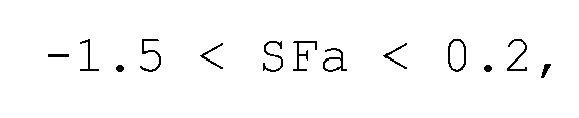
where r1 represents the curvature radius of the object side surface and r2 represents the curvature radius of the image side surface under the assumption that the curvature radius of the aspherical lens FE is defined as a curvature radius of a spherical surface that has a center of curvature radius on the optical axis and contains three points: a vertex of the aspherical lens FE; and both ends of the maximum effective diameter of the aspherical lens FE. - Condition (5) is added to make the value of the distortion generated by the fisheye attachment FE appropriate so as to give a suitable fisheye effect. Below the lower limit of condition (5), the negative distortion becomes too high to give a suitable fisheye effect, or off-axial principal rays cannot be incident on the object side surface of the negative lens, which leads to eclipse. On the other hand, above the upper limit, the negative distortion becomes too low to give a suitable fisheye effect, or the curvature of the image-side surface of the negative lens becomes so large that it becomes difficult to make such a lens. Generally, an imaging optical system for image-pickup is designed with a suppressed distortion. The imaging relationship in terms of the image height y, the incidence angle θ of off-axis principal rays and the focal length f of the lens is expressed approximately by the following equation.

- To give an ideal fisheye effect, it is desirable that a negative distortion be generated in the fisheye attachment FE so that the following condition concerning the focal length conversion magnification βFE of the fisheye attachment is satisfied.

- Fig. 2 is a cross-sectional view of the master lens M, at the wide-angle end, to which the fisheye attachment FE is to be attached.
- In the following, a numerical example of the master lens M will be described. In the following table, R represents the curvature radius of each lens surface of the master lens M, D represents the surface interval, N represents the refractive index for the e-line, and ν represents the Abbe number. In addition, f represents the focal length of the entire system, Fno represents the F number, Bf represents the back focus, 2ω represents the angle of field, and Y represents the image height.
- Here, the angle of field 2ω is one in the case where distortion is not taken into account. When distortion is taken into account, the angle of field A can be calculated from the following equation using the value Di (%) of the distortion at the 100% image height in each aberration diagram.

- In Table 1, examples of various values on the master lens M are presented.
- Table 1
Diagonal Screen Size: 11 mm f=9.5 - 185.25, Fno=1.850- 2.850, 2ω=60.1° - 3.4° R1 = 600.261, D1 = 2.20, N1 = 1.7617, ν1 = 27.51 R2 = 81.461, D2 = 11.42, N2 = 1.4985, ν2 = 81.61 R3 = -290.956, D3 = 7.63 R4 = 86.701, D4 = 7.86, N3 = 1.6229, ν3 = 60.28 R5 = 3044.710, D5 = 0.15 R6 = 66.016, D6 = 6.01, N4 = 1.7323, ν4 = 54.68 R7 = 145.709, D7 = variable R8 = 111.445, D8 = 0.80, N5 = 1.8881, ν5 = 40.78 R9 = 16.812, D9 = 4.65 R10= -47.8421, D10= 0.70, N6 = 1.8202, ν6 = 46.62 R11= 33.779, D11= 2.24 R12= 28.944, D12= 5.20, N7 = 1.8126, ν7 = 25.43 R13= -29.192, D13= 0.54 R14= -24.664, D14= 0.70, N8 = 1.7920, ν8 = 47.38 R15= 132.572, D15= variable R16= -28.806, D16= 0.75, N9 = 1.7468, ν9 = 49.31 R17= 37.218, D17= 3.81, N10= 1.8550, ν10= 23.89 R18= 449.023, D18= variable R19= stop, D19= 1.80 R20= ∞, D20= 3.79, N11= 1.7279, ν11= 38.03 R21= -46.584, D21= 0,20 R22= 166.702, D22= 3.92, N12= 1.5131, ν12= 60.49 R23= -63.568, D23= 0,20 R24= 42.1598, D24= 8.34, N13= 1.4891, ν13= 70.21 R25= -33.917, D25= 1.66, N14= 1.8393, ν14= 37.17 R26= 172.175, D26= 21.27 R27= 111.436, D27= 6.19, N15= 1.5035, ν15= 56.4 R28= -44.823, D28= 0.20 R29= 82.661, D29= 1.40, N16= 1.8393, ν16= 37.17 R30= 20.646, D30= 7.09, N17= 1.5035, ν17= 56.4 R31= 284.915, D31= 0.20 R32= 60.636, D32= 7.53, N18= 1.5183, ν18= 64.15 R33= -24.607, D33= 1.40, N19=1.8081, ν19= 46.58 R34= 105.806, D34= 0.30 R35= 44.171, D35= 6.68, N20= 1.5035, ν20= 56.4 R36= -37.129, D36=5.00 R37= ∞, D37= 30.00, N21= 1.6072, ν21= 38.01 R38= ∞, D38= 16.20, N22= 1.5183, ν22= 64.15 R39= ∞, focal length 9.50, 38.86, 185.25 variable distance D7 0.65, 35.96, 52.03 D15 53.75, 13.38, 6.33 D18 5.10, 10.15, 1.15 Bf 9.9366 Y 5.5 - When the fisheye attachment FE is attached on the master lens M, surfaces R27 to R36 in the master lens M are moved parallel to the optical axis as a unit to effect focusing.
- Fig. 3 shows aberrations of the master lens M at the wide-angle end, where aberrations for the e-line are designated by "e", aberrations for the g-line is designated by "g", the meridional image plane is designated by "m", and the sagittal image plane is designated by "s".
- The fisheye attachment FE according to the first embodiment includes a lens having an aspherical surface r2 with a negative refractive power. The aspherical surface shape is expressed by the following equation (10), where the coordinate along the optical axis is represented by x, the coordinate along the direction perpendicular to the optical axis is represented by y, r represents a reference curvature radius, k represents the conic constant, and Cn represents the n-th order aspherical coefficient.

- Fig. 1 is a cross-sectional view of the lens in the state in which the above-described fisheye attachment FE according to the first embodiment is attached on the master lens M that is set to the wide-angle end. Fig. 4 shows aberrations in that state.
- In Table 2 are presented various values on a first numerical embodiment of the fisheye attachment FE according to the first embodiment.
- In Table 2, n represents the refractive index for the e-line, and ν represents the Abbe number. In addition, r represents the curvature radius of each lens surface in the fisheye attachment FE, d represents the surface interval, r* represents the curvature radius of the aspherical lens FE is defined as a curvature radius of a reference spherical surface that has a center of curvature radius on the optical axis and contains three points: a vertex of the aspherical lens; and both ends of the maximum effective diameter of the aspherical lens, and r** represents the local curvature radius of the aspherical surface.
-
Table 2 r1 = -963.909 d1 = 5.00 n1 = 1.6055 v1 = 60.64 r2 = 51.236 d2 = 17.15 r2* = 55.399 r2** = 49.368 Aspherical Coefficient: C2 = 3.6928·10-4 C4 = -1.0542·10-6 C6 = -2.128210-11 C8 = -2.8396·10-14 C10 = -1.0588·10-16 K = 0.0000 - (Second Embodiment)
- Fig. 5 is a cross-sectional view of the lens in the state in which a fisheye attachment FE according to a second embodiment is attached on the master lens M that is set to the wide-angle end. Fig. 6 shows aberrations in that state.
- In Table 3 are presented various values on a second numerical embodiment of the fisheye attachment FE according to the second embodiment.
-
Table 3 r1 = -284.668 d1 = 5.00 n1 = 1.8881 v1 = 40.76 r2 = 81.892 d2 = 6.47 r2* = 244.164 r2** = 183.488 Aspherical Coefficient: C2 = -3.3806·10-3 C4 = -1.0428·10-6 C6 = 2.2389·10-10 C8 = -2.8564·10-14 C10 = -2.1355·10-17 K = 0.0000 - (Third Embodiment)
- Fig. 7 is a cross-sectional view of the lens in the state in which a fisheye attachment FE according to a third embodiment is attached on the master lens M that is set to the wide-angle end. Fig. 8 shows aberrations in that state.
- In Table 4 are presented various values on a third numerical embodiment of the fisheye attachment FE according to the third embodiment.
-
Table 4 r1 = 2948.256 d1 = 5.00 n1 = 1.6055 v1 = 60.64 r2 = 39.699 d2 = 26.06 r2* = 39.921 r2** = 35.253 Aspherical Coefficient: C2 = 1.5886·10-3 C4 = 3.7774·10-6 C6 = -1.0319·10-8 C8 = 9.1386·10-12 C10 = -3.5774·10-15 K = 0.0000 - (Fourth Embodiment)
- Fig. 9 is a cross-sectional view of the lens in the state in which a fisheye attachment FE according to a fourth embodiment is attached on the master lens M that is set to the wide-angle end. Fig. 10 shows aberrations in that state.
- In Table 5 are presented various values on a fourth numerical embodiment of the fisheye attachment FE according to the fourth embodiment.
-
Table 5 r1 = -141.812 d1 = 5.00 n1 = 1.4891 v1 = 70.23 r2 = 96.250 d2 = 7.46 r2* = 170.220 r2** = 113.986 Aspherical Coefficient: C2 = -8.0830·10-4 C4 = -1.5102·10-6 C6 = -2.8377·10-11 C8 = 2.2062·10-13 C10 = -1.1604·10-16 K = 0.0000 - (Fifth Embodiment)
- Fig. 11 is a cross-sectional view of the lens in the state in which a fisheye attachment FE according to a fifth embodiment is attached on the master lens M that is set to the wide-angle end. Fig. 12 shows aberrations in that state.
- In Table 6 are presented various values on a fifth numerical embodiment of the fisheye attachment FE according to the fifth embodiment.
-
Table 6 r1 = 675.725 d1 = 5.00 n1 = 1.8881 v1 = 40.76 r2 = 64.469 d2 = 15.46 r2*= 62.291 r2** = 60.330 Aspherical Coefficient: C2 = 5.3205·10-4 C4 = 5.3502·10-8 C6 = -1.1670·10-10 C8 = -4.2160·10-14 C10 = -2.4278·10-17 K = 0.0000 - Table 7 shows the values associated with conditions (2), (3), (4) and (5) in numerical examples 1 to 5.
-
Table 7 Embodiment 1 Embodiment 2 Embodiment 3Embodiment 4 Embodiment 5 Fe -77.418 -124.996 -58.965 -128.365 -74.874 (2) |Δ7/fe| 4.4815·10-3 1.2821·10-3 1.7452·10-2 3.0056·10-3 1.5752·10-3 (3) |Δ4/Δ7| 0.4950 0.5889 0.3757 0.5533 0.3920 (4) |Δ9/Δ7| 0.7046 0.5829 0.8561 0.6107 0.8272 (5) SFa -0.8913 -0.0766 -1.0275 0.0910 -1.2031 - According to the first to fifth embodiments, the fisheye lens attachment FE includes a lens having an aspherical surface r2 with a negative refractive power that satisfies conditions (2) through (5). With these conditions, a large negative distortion is generated. Thus, a fisheye attachment FE that is satisfactorily corrected in terms of astigmatism and field curvature while having a suitable fisheye effect can be provided.
- While the present invention has been described with reference to exemplary embodiments, it is to be understood that the invention is not limited to the disclosed exemplary embodiments. The scope of the following claims is to be accorded the broadest interpretation so as to encompass all such modifications and equivalent structures and functions.
Claims (5)
- An optical accessory arranged to change an optical characteristic of a shooting lens and to be detachably attached to an object side of a shooting lens, wherein the optical accessory includes at least one lens FE having a negative refractive power, the image-side surface of the lens FE being an aspherical surface having a negative refractive power that decreases from the optical axis to its peripheral portion.
- An optical accessory according to claim 1, wherein the following conditions are satisfied:


where fe represents the focal length of the lens FE, and Δ9, Δ7 and Δ4 respectively represent the aspherical amounts at the image heights of 90%, 70% and 40% of the effective diameter of the lens FE having the aspherical surface, the aspherical amount is defined by a distance between the aspherical surface of the aspherical lens FE and a spherical surface along the optical axis direction, where the spherical surface has a center of curvature radius on the optical axis and contains three points: a vertex of the aspherical lens FE; and both ends of the maximum effective diameter of the aspherical lens FE. - An optical accessory according to claim 1 or 2 wherein the following conditions are satisfied:

where r1 represents the curvature radius of the object side surface of the lens FE and r2 represents the curvature radius of the image-side surface of the lens FE, the curvature radius of the aspherical lens FE is defined by a curvature radius of a spherical surface that has a center of curvature radius on the optical axis and contains three points: a vertex of the aspherical lens FE; and both ends of the maximum effective diameter of the aspherical lens FE. - A shooting lens on which an optical accessory according to any one of claims 1 to 3 is attached.
- An image-pickup apparatus comprising an optical accessory according to any one of claims 1 to 3 and a shooting lens on which the optical accessory is attached.
Applications Claiming Priority (1)
| Application Number | Priority Date | Filing Date | Title |
|---|---|---|---|
| JP2006080461A JP4908887B2 (en) | 2006-03-23 | 2006-03-23 | Fish eye attachment |
Publications (2)
| Publication Number | Publication Date |
|---|---|
| EP1837691A1 true EP1837691A1 (en) | 2007-09-26 |
| EP1837691B1 EP1837691B1 (en) | 2011-06-15 |
Family
ID=37991589
Family Applications (1)
| Application Number | Title | Priority Date | Filing Date |
|---|---|---|---|
| EP07103945A Not-in-force EP1837691B1 (en) | 2006-03-23 | 2007-03-12 | Fisheye converter for a telephoto zoom lens |
Country Status (4)
| Country | Link |
|---|---|
| US (1) | US7675693B2 (en) |
| EP (1) | EP1837691B1 (en) |
| JP (1) | JP4908887B2 (en) |
| AT (1) | ATE513241T1 (en) |
Cited By (4)
| Publication number | Priority date | Publication date | Assignee | Title |
|---|---|---|---|---|
| CN106597647A (en) * | 2015-10-14 | 2017-04-26 | 佳能株式会社 | Optical system and image pickup apparatus including the same |
| CN107450161A (en) * | 2017-09-15 | 2017-12-08 | 江西联创电子有限公司 | New fish eye lens |
| CN110673313A (en) * | 2019-09-27 | 2020-01-10 | 上海电机学院 | Zoom fisheye lens system and design method |
| CN111208630A (en) * | 2020-04-23 | 2020-05-29 | 江西联创电子有限公司 | External lens |
Families Citing this family (3)
| Publication number | Priority date | Publication date | Assignee | Title |
|---|---|---|---|---|
| JP2009505120A (en) * | 2005-08-11 | 2009-02-05 | グローバル バイオニック オプティクス ピーティワイ リミテッド | Optical lens system |
| US20090168163A1 (en) * | 2005-11-01 | 2009-07-02 | Global Bionic Optics Pty Ltd. | Optical lens systems |
| JP7061980B2 (en) * | 2019-03-26 | 2022-05-02 | 富士フイルム株式会社 | Zoom lens and image pickup device |
Citations (2)
| Publication number | Priority date | Publication date | Assignee | Title |
|---|---|---|---|---|
| JPS62138814A (en) * | 1985-12-12 | 1987-06-22 | Canon Inc | Switchable variable magnification optical system |
| JPH0540221A (en) * | 1991-08-07 | 1993-02-19 | Nikon Corp | Wide converter |
Family Cites Families (8)
| Publication number | Priority date | Publication date | Assignee | Title |
|---|---|---|---|---|
| US4961085A (en) * | 1988-07-15 | 1990-10-02 | Fuji Photo Film Co., Ltd. | Lens fitted film package |
| JP3585297B2 (en) * | 1995-09-12 | 2004-11-04 | オリンパス株式会社 | Objective lens |
| DE69728183T2 (en) * | 1996-11-29 | 2005-03-17 | 3M Innovative Properties Co., St. Paul | LENSES FOR ELECTRONIC PICTURE SYSTEMS |
| JPH11214293A (en) * | 1998-01-22 | 1999-08-06 | Nikon Corp | Projection optical system, exposure apparatus having the optical system, and device manufacturing method |
| JP3008926B2 (en) | 1998-04-16 | 2000-02-14 | 株式会社ニコン | Fish icon barter and photographing lens system equipped with the fish icon barter |
| JP2000292696A (en) * | 1999-04-12 | 2000-10-20 | Enplas Corp | Image pickup device and attachment lens |
| JP4527363B2 (en) * | 2003-04-21 | 2010-08-18 | 株式会社オートネットワーク技術研究所 | In-vehicle camera device |
| JP4477336B2 (en) * | 2003-10-15 | 2010-06-09 | オリンパス株式会社 | Zoom lens and electronic imaging apparatus using the same |
-
2006
- 2006-03-23 JP JP2006080461A patent/JP4908887B2/en not_active Expired - Fee Related
-
2007
- 2007-03-08 US US11/683,715 patent/US7675693B2/en not_active Expired - Fee Related
- 2007-03-12 AT AT07103945T patent/ATE513241T1/en not_active IP Right Cessation
- 2007-03-12 EP EP07103945A patent/EP1837691B1/en not_active Not-in-force
Patent Citations (2)
| Publication number | Priority date | Publication date | Assignee | Title |
|---|---|---|---|---|
| JPS62138814A (en) * | 1985-12-12 | 1987-06-22 | Canon Inc | Switchable variable magnification optical system |
| JPH0540221A (en) * | 1991-08-07 | 1993-02-19 | Nikon Corp | Wide converter |
Cited By (5)
| Publication number | Priority date | Publication date | Assignee | Title |
|---|---|---|---|---|
| CN106597647A (en) * | 2015-10-14 | 2017-04-26 | 佳能株式会社 | Optical system and image pickup apparatus including the same |
| US10649184B2 (en) | 2015-10-14 | 2020-05-12 | Canon Kabushiki Kaisha | Optical system and image pickup apparatus including the same |
| CN107450161A (en) * | 2017-09-15 | 2017-12-08 | 江西联创电子有限公司 | New fish eye lens |
| CN110673313A (en) * | 2019-09-27 | 2020-01-10 | 上海电机学院 | Zoom fisheye lens system and design method |
| CN111208630A (en) * | 2020-04-23 | 2020-05-29 | 江西联创电子有限公司 | External lens |
Also Published As
| Publication number | Publication date |
|---|---|
| JP2007256602A (en) | 2007-10-04 |
| US20070223101A1 (en) | 2007-09-27 |
| US7675693B2 (en) | 2010-03-09 |
| EP1837691B1 (en) | 2011-06-15 |
| JP4908887B2 (en) | 2012-04-04 |
| ATE513241T1 (en) | 2011-07-15 |
Similar Documents
| Publication | Publication Date | Title |
|---|---|---|
| US7773311B2 (en) | Zoom lens and image pickup apparatus including the same | |
| CN109283669B (en) | Zoom lens and image pickup apparatus | |
| JP4810133B2 (en) | Zoom lens and imaging apparatus having the same | |
| US7864445B2 (en) | Zoom lens and image pickup apparatus including the same | |
| JP6566646B2 (en) | Zoom lens and imaging apparatus having the same | |
| US7630144B2 (en) | Zoom lens and image pickup apparatus having zoom lens | |
| US6002528A (en) | Zoom lens | |
| US20010013980A1 (en) | Zoom lens system | |
| EP2026113A1 (en) | Zoom lens of the telephoto type having four lens groups | |
| US11022783B2 (en) | Zoom lens and image pickup apparatus | |
| JP2009223008A5 (en) | ||
| US6931207B2 (en) | Zoom lens system and camera having the same | |
| JP2001350092A (en) | Image pickup lens device | |
| EP1837691B1 (en) | Fisheye converter for a telephoto zoom lens | |
| JP6808441B2 (en) | Zoom lens and imaging device with it | |
| JP4313864B2 (en) | Zoom lens | |
| JP4829586B2 (en) | Zoom lens and imaging apparatus having the same | |
| JP4405747B2 (en) | Zoom lens and imaging apparatus having the same | |
| EP1959286B1 (en) | Zoom lens and image pickup apparatus having the same | |
| JP2014029375A (en) | Zoom lens and imaging apparatus including the same | |
| JP4776936B2 (en) | Zoom lens and imaging apparatus having the same | |
| JP4794915B2 (en) | Zoom lens and imaging apparatus having the same | |
| JP5656684B2 (en) | Zoom lens and imaging apparatus having the same | |
| JP4971632B2 (en) | Zoom lens and imaging apparatus having the same | |
| JP2017215410A (en) | Zoom lens and imaging device having the same |
Legal Events
| Date | Code | Title | Description |
|---|---|---|---|
| PUAI | Public reference made under article 153(3) epc to a published international application that has entered the european phase |
Free format text: ORIGINAL CODE: 0009012 |
|
| AK | Designated contracting states |
Kind code of ref document: A1 Designated state(s): AT BE BG CH CY CZ DE DK EE ES FI FR GB GR HU IE IS IT LI LT LU LV MC MT NL PL PT RO SE SI SK TR |
|
| AX | Request for extension of the european patent |
Extension state: AL BA HR MK YU |
|
| 17P | Request for examination filed |
Effective date: 20080326 |
|
| AKX | Designation fees paid |
Designated state(s): AT BE BG CH CY CZ DE DK EE ES FI FR GB GR HU IE IS IT LI LT LU LV MC MT NL PL PT RO SE SI SK TR |
|
| 17Q | First examination report despatched |
Effective date: 20090806 |
|
| GRAP | Despatch of communication of intention to grant a patent |
Free format text: ORIGINAL CODE: EPIDOSNIGR1 |
|
| GRAS | Grant fee paid |
Free format text: ORIGINAL CODE: EPIDOSNIGR3 |
|
| GRAA | (expected) grant |
Free format text: ORIGINAL CODE: 0009210 |
|
| AK | Designated contracting states |
Kind code of ref document: B1 Designated state(s): AT BE BG CH CY CZ DE DK EE ES FI FR GB GR HU IE IS IT LI LT LU LV MC MT NL PL PT RO SE SI SK TR |
|
| REG | Reference to a national code |
Ref country code: CH Ref legal event code: EP Ref country code: GB Ref legal event code: FG4D |
|
| REG | Reference to a national code |
Ref country code: IE Ref legal event code: FG4D |
|
| REG | Reference to a national code |
Ref country code: DE Ref legal event code: R096 Ref document number: 602007015178 Country of ref document: DE Effective date: 20110721 |
|
| REG | Reference to a national code |
Ref country code: NL Ref legal event code: VDEP Effective date: 20110615 |
|
| PG25 | Lapsed in a contracting state [announced via postgrant information from national office to epo] |
Ref country code: LT Free format text: LAPSE BECAUSE OF FAILURE TO SUBMIT A TRANSLATION OF THE DESCRIPTION OR TO PAY THE FEE WITHIN THE PRESCRIBED TIME-LIMIT Effective date: 20110615 Ref country code: SE Free format text: LAPSE BECAUSE OF FAILURE TO SUBMIT A TRANSLATION OF THE DESCRIPTION OR TO PAY THE FEE WITHIN THE PRESCRIBED TIME-LIMIT Effective date: 20110615 |
|
| PG25 | Lapsed in a contracting state [announced via postgrant information from national office to epo] |
Ref country code: CY Free format text: LAPSE BECAUSE OF FAILURE TO SUBMIT A TRANSLATION OF THE DESCRIPTION OR TO PAY THE FEE WITHIN THE PRESCRIBED TIME-LIMIT Effective date: 20110615 Ref country code: SI Free format text: LAPSE BECAUSE OF FAILURE TO SUBMIT A TRANSLATION OF THE DESCRIPTION OR TO PAY THE FEE WITHIN THE PRESCRIBED TIME-LIMIT Effective date: 20110615 Ref country code: LV Free format text: LAPSE BECAUSE OF FAILURE TO SUBMIT A TRANSLATION OF THE DESCRIPTION OR TO PAY THE FEE WITHIN THE PRESCRIBED TIME-LIMIT Effective date: 20110615 Ref country code: FI Free format text: LAPSE BECAUSE OF FAILURE TO SUBMIT A TRANSLATION OF THE DESCRIPTION OR TO PAY THE FEE WITHIN THE PRESCRIBED TIME-LIMIT Effective date: 20110615 Ref country code: AT Free format text: LAPSE BECAUSE OF FAILURE TO SUBMIT A TRANSLATION OF THE DESCRIPTION OR TO PAY THE FEE WITHIN THE PRESCRIBED TIME-LIMIT Effective date: 20110615 Ref country code: GR Free format text: LAPSE BECAUSE OF FAILURE TO SUBMIT A TRANSLATION OF THE DESCRIPTION OR TO PAY THE FEE WITHIN THE PRESCRIBED TIME-LIMIT Effective date: 20110916 |
|
| PG25 | Lapsed in a contracting state [announced via postgrant information from national office to epo] |
Ref country code: NL Free format text: LAPSE BECAUSE OF FAILURE TO SUBMIT A TRANSLATION OF THE DESCRIPTION OR TO PAY THE FEE WITHIN THE PRESCRIBED TIME-LIMIT Effective date: 20110615 Ref country code: BE Free format text: LAPSE BECAUSE OF FAILURE TO SUBMIT A TRANSLATION OF THE DESCRIPTION OR TO PAY THE FEE WITHIN THE PRESCRIBED TIME-LIMIT Effective date: 20110615 |
|
| PG25 | Lapsed in a contracting state [announced via postgrant information from national office to epo] |
Ref country code: CZ Free format text: LAPSE BECAUSE OF FAILURE TO SUBMIT A TRANSLATION OF THE DESCRIPTION OR TO PAY THE FEE WITHIN THE PRESCRIBED TIME-LIMIT Effective date: 20110615 Ref country code: EE Free format text: LAPSE BECAUSE OF FAILURE TO SUBMIT A TRANSLATION OF THE DESCRIPTION OR TO PAY THE FEE WITHIN THE PRESCRIBED TIME-LIMIT Effective date: 20110615 Ref country code: PT Free format text: LAPSE BECAUSE OF FAILURE TO SUBMIT A TRANSLATION OF THE DESCRIPTION OR TO PAY THE FEE WITHIN THE PRESCRIBED TIME-LIMIT Effective date: 20111017 Ref country code: IS Free format text: LAPSE BECAUSE OF FAILURE TO SUBMIT A TRANSLATION OF THE DESCRIPTION OR TO PAY THE FEE WITHIN THE PRESCRIBED TIME-LIMIT Effective date: 20111015 |
|
| PG25 | Lapsed in a contracting state [announced via postgrant information from national office to epo] |
Ref country code: RO Free format text: LAPSE BECAUSE OF FAILURE TO SUBMIT A TRANSLATION OF THE DESCRIPTION OR TO PAY THE FEE WITHIN THE PRESCRIBED TIME-LIMIT Effective date: 20110615 Ref country code: SK Free format text: LAPSE BECAUSE OF FAILURE TO SUBMIT A TRANSLATION OF THE DESCRIPTION OR TO PAY THE FEE WITHIN THE PRESCRIBED TIME-LIMIT Effective date: 20110615 Ref country code: PL Free format text: LAPSE BECAUSE OF FAILURE TO SUBMIT A TRANSLATION OF THE DESCRIPTION OR TO PAY THE FEE WITHIN THE PRESCRIBED TIME-LIMIT Effective date: 20110615 |
|
| PLBE | No opposition filed within time limit |
Free format text: ORIGINAL CODE: 0009261 |
|
| STAA | Information on the status of an ep patent application or granted ep patent |
Free format text: STATUS: NO OPPOSITION FILED WITHIN TIME LIMIT |
|
| 26N | No opposition filed |
Effective date: 20120316 |
|
| PG25 | Lapsed in a contracting state [announced via postgrant information from national office to epo] |
Ref country code: IT Free format text: LAPSE BECAUSE OF FAILURE TO SUBMIT A TRANSLATION OF THE DESCRIPTION OR TO PAY THE FEE WITHIN THE PRESCRIBED TIME-LIMIT Effective date: 20110615 |
|
| PG25 | Lapsed in a contracting state [announced via postgrant information from national office to epo] |
Ref country code: DK Free format text: LAPSE BECAUSE OF FAILURE TO SUBMIT A TRANSLATION OF THE DESCRIPTION OR TO PAY THE FEE WITHIN THE PRESCRIBED TIME-LIMIT Effective date: 20110615 |
|
| REG | Reference to a national code |
Ref country code: DE Ref legal event code: R097 Ref document number: 602007015178 Country of ref document: DE Effective date: 20120316 |
|
| PG25 | Lapsed in a contracting state [announced via postgrant information from national office to epo] |
Ref country code: MC Free format text: LAPSE BECAUSE OF NON-PAYMENT OF DUE FEES Effective date: 20120331 |
|
| REG | Reference to a national code |
Ref country code: CH Ref legal event code: PL |
|
| REG | Reference to a national code |
Ref country code: FR Ref legal event code: ST Effective date: 20121130 |
|
| REG | Reference to a national code |
Ref country code: IE Ref legal event code: MM4A |
|
| PG25 | Lapsed in a contracting state [announced via postgrant information from national office to epo] |
Ref country code: IE Free format text: LAPSE BECAUSE OF NON-PAYMENT OF DUE FEES Effective date: 20120312 Ref country code: LI Free format text: LAPSE BECAUSE OF NON-PAYMENT OF DUE FEES Effective date: 20120331 Ref country code: CH Free format text: LAPSE BECAUSE OF NON-PAYMENT OF DUE FEES Effective date: 20120331 Ref country code: FR Free format text: LAPSE BECAUSE OF NON-PAYMENT OF DUE FEES Effective date: 20120402 |
|
| PG25 | Lapsed in a contracting state [announced via postgrant information from national office to epo] |
Ref country code: ES Free format text: LAPSE BECAUSE OF FAILURE TO SUBMIT A TRANSLATION OF THE DESCRIPTION OR TO PAY THE FEE WITHIN THE PRESCRIBED TIME-LIMIT Effective date: 20110926 |
|
| PG25 | Lapsed in a contracting state [announced via postgrant information from national office to epo] |
Ref country code: BG Free format text: LAPSE BECAUSE OF FAILURE TO SUBMIT A TRANSLATION OF THE DESCRIPTION OR TO PAY THE FEE WITHIN THE PRESCRIBED TIME-LIMIT Effective date: 20110915 |
|
| PG25 | Lapsed in a contracting state [announced via postgrant information from national office to epo] |
Ref country code: MT Free format text: LAPSE BECAUSE OF FAILURE TO SUBMIT A TRANSLATION OF THE DESCRIPTION OR TO PAY THE FEE WITHIN THE PRESCRIBED TIME-LIMIT Effective date: 20110615 |
|
| PG25 | Lapsed in a contracting state [announced via postgrant information from national office to epo] |
Ref country code: TR Free format text: LAPSE BECAUSE OF FAILURE TO SUBMIT A TRANSLATION OF THE DESCRIPTION OR TO PAY THE FEE WITHIN THE PRESCRIBED TIME-LIMIT Effective date: 20110615 |
|
| PG25 | Lapsed in a contracting state [announced via postgrant information from national office to epo] |
Ref country code: LU Free format text: LAPSE BECAUSE OF NON-PAYMENT OF DUE FEES Effective date: 20120312 |
|
| PG25 | Lapsed in a contracting state [announced via postgrant information from national office to epo] |
Ref country code: HU Free format text: LAPSE BECAUSE OF FAILURE TO SUBMIT A TRANSLATION OF THE DESCRIPTION OR TO PAY THE FEE WITHIN THE PRESCRIBED TIME-LIMIT Effective date: 20070312 |
|
| PGFP | Annual fee paid to national office [announced via postgrant information from national office to epo] |
Ref country code: GB Payment date: 20200326 Year of fee payment: 14 |
|
| PGFP | Annual fee paid to national office [announced via postgrant information from national office to epo] |
Ref country code: DE Payment date: 20200528 Year of fee payment: 14 |
|
| REG | Reference to a national code |
Ref country code: DE Ref legal event code: R119 Ref document number: 602007015178 Country of ref document: DE |
|
| GBPC | Gb: european patent ceased through non-payment of renewal fee |
Effective date: 20210312 |
|
| PG25 | Lapsed in a contracting state [announced via postgrant information from national office to epo] |
Ref country code: GB Free format text: LAPSE BECAUSE OF NON-PAYMENT OF DUE FEES Effective date: 20210312 Ref country code: DE Free format text: LAPSE BECAUSE OF NON-PAYMENT OF DUE FEES Effective date: 20211001 |