EP1837597A2 - Burner for combustion chamber and combustion method - Google Patents
Burner for combustion chamber and combustion method Download PDFInfo
- Publication number
- EP1837597A2 EP1837597A2 EP07251103A EP07251103A EP1837597A2 EP 1837597 A2 EP1837597 A2 EP 1837597A2 EP 07251103 A EP07251103 A EP 07251103A EP 07251103 A EP07251103 A EP 07251103A EP 1837597 A2 EP1837597 A2 EP 1837597A2
- Authority
- EP
- European Patent Office
- Prior art keywords
- mixing portion
- combustion
- blowing ports
- burner
- fuel
- Prior art date
- Legal status (The legal status is an assumption and is not a legal conclusion. Google has not performed a legal analysis and makes no representation as to the accuracy of the status listed.)
- Granted
Links
Images


Classifications
-
- F—MECHANICAL ENGINEERING; LIGHTING; HEATING; WEAPONS; BLASTING
- F23—COMBUSTION APPARATUS; COMBUSTION PROCESSES
- F23C—METHODS OR APPARATUS FOR COMBUSTION USING FLUID FUEL OR SOLID FUEL SUSPENDED IN A CARRIER GAS OR AIR
- F23C7/00—Combustion apparatus characterised by arrangements for air supply
- F23C7/002—Combustion apparatus characterised by arrangements for air supply the air being submitted to a rotary or spinning motion
-
- F—MECHANICAL ENGINEERING; LIGHTING; HEATING; WEAPONS; BLASTING
- F23—COMBUSTION APPARATUS; COMBUSTION PROCESSES
- F23R—GENERATING COMBUSTION PRODUCTS OF HIGH PRESSURE OR HIGH VELOCITY, e.g. GAS-TURBINE COMBUSTION CHAMBERS
- F23R3/00—Continuous combustion chambers using liquid or gaseous fuel
- F23R3/02—Continuous combustion chambers using liquid or gaseous fuel characterised by the air-flow or gas-flow configuration
- F23R3/04—Air inlet arrangements
- F23R3/10—Air inlet arrangements for primary air
- F23R3/12—Air inlet arrangements for primary air inducing a vortex
-
- F—MECHANICAL ENGINEERING; LIGHTING; HEATING; WEAPONS; BLASTING
- F23—COMBUSTION APPARATUS; COMBUSTION PROCESSES
- F23R—GENERATING COMBUSTION PRODUCTS OF HIGH PRESSURE OR HIGH VELOCITY, e.g. GAS-TURBINE COMBUSTION CHAMBERS
- F23R3/00—Continuous combustion chambers using liquid or gaseous fuel
- F23R3/28—Continuous combustion chambers using liquid or gaseous fuel characterised by the fuel supply
- F23R3/286—Continuous combustion chambers using liquid or gaseous fuel characterised by the fuel supply having fuel-air premixing devices
-
- F—MECHANICAL ENGINEERING; LIGHTING; HEATING; WEAPONS; BLASTING
- F23—COMBUSTION APPARATUS; COMBUSTION PROCESSES
- F23D—BURNERS
- F23D2900/00—Special features of, or arrangements for burners using fluid fuels or solid fuels suspended in a carrier gas
- F23D2900/14—Special features of gas burners
- F23D2900/14021—Premixing burners with swirling or vortices creating means for fuel or air
Definitions
- the present invention was achieved in view of the above circumstances, and has as its object to provide a burner for combustion chamber and a combustion method that can shorten the flame length in the central axial direction of the burner for combustion chamber by improving the combustion efficiency even during low loading and shorten the overall length of the burner for combustion chamber in the central axial direction.
- a first solving means adopts a burner for combustion chamber that is provided with: a cylindrical mixing portion that mixes an oxidizing agent and fuel in the interior thereof, with one end opening to a combustion portion; a fuel spraying portion that sprays fuel in the mixing portion, being disposed on another end of the mixing portion; first blowing ports that introduce the oxidizing agent to the mixing portion to form a swirling flow with the fuel, being disposed to open to the inner wall of the mixing portion; and second blowing ports that additionally introduce the oxidizing agent to the mixing portion, opening in a direction different from the first blowing ports and being disposed further to the other end side of the mixing portion than the swirling flow.
- the flammable zone in the combustion portion at the one end side of the mixing portion can be greatly expanded in the diameter direction by the moderate swirling that remains and the large turbulence. As a result, it is possible to shorten the distance between the combustion portion and the mixing portion.
- the second solving means according to the present invention adopts a burner for combustion chamber in which, in the first means described above, the first blowing ports open in the circumferential direction of the mixing portion; and the second blowing ports are provided to open in the central axial direction of the mixing portion, and are disposed further to the inside of the first blowing ports in the radial direction of the mixing portion.
- the first blowing ports and the second blowing ports open in intersecting directions, when the oxidizing agent is introduced from both, it is possible to form an air-fuel mixture having large turbulence in the mixing portion and possible to quickly move the air-fuel mixture to the combustion portion quickly. Accordingly, occurrences of back firing and self ignition in the mixing portion can be suitably inhibited.
- the third solving means according to the present invention adopts a burner for combustion chamber in which, in the first means described above, the distal end of the fuel spraying portion is disposed projecting to the position of the first blowing ports along the central axis of the mixing portion.
- the strong swirling flow due to the oxidizing agent that is introduced from the first blowing ports collides with the distal end of the fuel spraying portion.
- a strong shear flow can be formed around the fuel spraying portion. Accordingly, it is possible to produce greater turbulence, which can accelerate rapid mixing.
- the fourth solving means according to the present invention adopts a combustion method characterized by forming a swirling flow in a cylindrical mixing portion in which one end opens to a combustion portion, by mixing fuel that is sprayed from the other end side into the mixing portion and an oxidizing agent that is introduced into the interior of the mixing portion from a wall surface thereof, and additionally introducing the oxidizing agent into the mixing portion in a direction different from the swirling flow and from further to the other end side of the mixing portion than the swirling flow.
- the present invention can shorten the flame length in the central axial direction of the burner for combustion chamber by improving the combustion efficiency even during low loading and can shorten the overall length of the burner for combustion chamber in the central axial direction.
- a burner 1 for combustion chamber is provided with the following: a cylindrical mixing portion 3 that mixes air for combustion (oxidizing agent) and fuel in the interior thereof, with one end 3 a opening to a combustion portion 2; a spray nozzle (fuel spraying portion) 5 that sprays fuel in the mixing portion 3, being disposed on another end 3b of the mixing portion 3; a plurality of first blowing ports 6 that introduce the air for combustion to the mixing portion 3 to form a swirling flow with the fuel, being disposed to open to the inner wall of the mixing portion 3; and a plurality of second blowing ports 7 that additionally introduce the air for combustion to the mixing portion 3, opening in a direction different from the flow of the swirling flow and being disposed further to the other end 3b side of the mixing portion 3 than the first blowing ports 6.
- the inner diameter of the mixing portion 3 is formed to be smaller than the inner diameter of the combustion portion 2.
- the first blowing ports 6 are provided in a direction perpendicular to the central axis C of the mixing portion 3 and, by obliquely penetrating the wall surface of the mixing portion 3 while sloping in the radial direction with respect to the circumferential direction of the mixing portion 3, open to the interior of the mixing portion 3.
- the first blowing ports 6 are equally spaced in the circumferential direction of the mixing portion 3.
- each of the second blowing ports 7 is provided extending along a central axis C2 which is parallel to the central axis C.
- the second blowing ports 7 are equally spaced from each other on same periphery of a circle around the central axis C of the mixing portion 3.
- the second blowing ports 7 are further to the inside of the first blowing ports 6 in the radial direction of the mixing portion 3, being disposed one-for-one for each first blowing port 6 at a position where the central axis C2 of the second blowing port intersects the central axis C1 of the first blowing port 6.
- the second blowing ports 7 are formed to open at both the one end 3a and the other end 3b of the mixing portion 3.
- air for combustion is introduced from the first blowing ports 6 and the second blowing ports 7 into the mixing portion 3, and fuel in a spray form is injected into the mixing portion 3 from the spray nozzle 5.
- the air for combustion that is introduced from the first blowing ports 6 flows across the inner wall surface of the mixing portion 3 in both a circumferential direction and an inward radial direction, so that a strong swirling flow is formed in the mixing portion 3.
- the air for combustion that is introduced from the second blowing ports 7 flows toward the combustion portion 2 in parallel with the central axis C to collide with the strong swirling flow.
- the strong swirling flow is partially destroyed to cause a vortex breakdown, with large turbulence being generated on the downstream side.
- the mixture of the air for combustion and the fuel is rapidly performed by this large turbulence to produce a lean mixture that moves to the combustion portion 2.
- the swirling flow is not completely destroyed, the lean mixture abruptly expands in diameter in the combustion portion 2.
- the lean mixture comes to have a wide flammable zone, so that a large flame 8 is generated by ignition.
- the burner 1 for combustion chamber and this combustion method can form a stronger turbulence state than in the case of forming only a strong swirling flow in the mixing portion, and therefore can rapidly accelerate the mixing of the fuel and the air for combustion.
- the flammable zone in the combustion portion 2 that is disposed downstream of the one end 3a of the mixing portion 3 can be greatly expanded in the diameter direction by the moderate swirling that remains and the large turbulence. Accordingly, it is possible to shorten the distance between the combustion portion 2 and the mixing portion 3.
- the flame length in the mixing portion 3 can be shortened in the direction of the central axis C, and the overall length of the burner 1 for combustion chamber can be shortened in the direction of the central axis C.
- first blowing ports 6 and the second blowing ports 7 open in directions that mutually intersect, when the air for combustion is introduced from both, it is possible to form a lean mixture having large turbulence in the mixing portion 3 and possible to quickly move the lean mixture to the combustion portion 2. Accordingly, occurrences of back firing and self ignition in the mixing portion 3 can be suitably inhibited.
- the point of difference of the second embodiment and the first embodiment is that a distal end 5a of the spray nozzle 5 in a burner 10 for combustion chamber according to the present embodiment is disposed projecting from another end 11b to the side of a distal end 11a of a mixing portion 11 along the central axis C until the disposed position of the first blowing ports 6.
- air for combustion is introduced from the first blowing ports 6 and the second blowing ports 7 into the mixing portion 11, and fuel in a spray form is injected into the mixing portion 11 from the spray nozzle 5.
- the mixture of the air for combustion and the fuel is rapidly performed. At this time, since the swirling flow is not completely destroyed similarly to the first embodiment, the lean mixture abruptly expands in diameter in the combustion portion 2.
- the burner 10 for combustion chamber and the combustion method of this embodiment can more rapidly mix the fuel and the air for combustion than the burner 1 for combustion chamber and the combustion method of the first embodiment by more extensively destroying the strong swirling flow, and can more stably perform ignition at low temperatures and at low loads.
- a second blowing port 16 of a burner 15 for combustion chamber according to the present embodiment is formed as a circular slit.
- This second blowing port 16 is approximately the same as the inner diameter of the second blowing ports 7 according to the first and second embodiments, and is provided in a manner that makes the second blowing ports 7 continuous in the circumferential direction.
- the outside diameter of a spray nozzle 17 is formed to be of a smaller diameter than the spray nozzle 5 according to the first and second embodiments, and the outside diameter of a mixing portion 18 is formed to be of a smaller diameter than the mixing portion 3 of the first embodiment and the mixing portion 11 of the second embodiment.
- the burner 15 for combustion chamber can exhibit the same action and effect as the aforedescribed other embodiments.
- the second blowing port 16 has a greater capacity than the second blowing ports 7 of the other embodiments, the flow rate of the air for combustion that is introduced to the mixing portion 18 can be made greater than in the other embodiments, and the flow distribution of the flow in the axial direction can be made greater than the flow in the radial direction. Accordingly, the outside diameter of the spray nozzle 17 and the mixing portion 18 can be reduced to achieve a reduction in weight.
- the distal end 5a of the spray nozzle 5 is not restricted to the aforedescribed embodiments, so long as it is at a position that produces a collision with the air for combustion that is introduced from the first blowing ports 6.
- a second blowing port 21 of a burner 20 for combustion chamber in addition to opening to one end 22a of a mixing portion 22, may be made to open to the outer circumferential surface of the mixing portion 22 instead of the side of the other end 22b.
- a mixing portion can be made taking into consideration the stress release of the spray nozzle 5.
- the size of the second blowing port may be adjustable, with the second blowing port not having a central axis that is parallel to the central axis C but instead being formed to slope so as to have a central axis that intersects the central axis C at a predetermined angle.
- the area of the flame generated in the combustion portion 2 could be expanded approximately three times with respect to the diameter in the visible region. Also, the length of the flame was reduced along the central axis of the burner and the combustion efficiency could be enhanced several percent accordingly.
Landscapes
- Engineering & Computer Science (AREA)
- Chemical & Material Sciences (AREA)
- Combustion & Propulsion (AREA)
- Mechanical Engineering (AREA)
- General Engineering & Computer Science (AREA)
- Gas Burners (AREA)
Abstract
Description
- The present invention relates to a burner for a combustion chamber that performs combustion by rapidly mixing fuel and an oxidizing agent such as air, and to a combustion method thereof.
- Priority is claimed on
Japanese Patent Application No. 2006-080881, filed March 23, 2006 - In recent years, there have been growing demands to reduce the concentration of nitrogen oxide (NOx) in the combustion exhaust of gas turbines and the like for the sake of environmental protection. In order to satisfactorily mix fuel and an oxidizing agent such as air, there has been proposed a burner having a cylindrical mixing portion in which fuel in a spray form and air for combustion, which is introduced from tangential to the cross section of the mixing portion, are introduced to generate a turbulent state by forming a strong swirling flow (refer, for example to
Japanese Unexamined Patent Application No. 2005-76989 - However, in the aforedescribed burner for combustion chamber and combustion method, a strong shearing area on the inner wall side of the mixing portion which causes flame extension and a rigid vortex area on the central axis side are formed by this strong swirling flow. Therefore, when the effect of the strong swirling flow is great, the strong swirling flow and the rigid vortex can end up being separated into a layer shape. In particular, in the case of a combustion chamber having a wide load range such as in an aircraft engine, when such a separation state occurs during a low load, the flame is formed only at the rigid vortex area, and the mixing of fuel and air therefore becomes insufficient, leading to a worsening of combustion stability and combustion efficiency. In such a case, ignition performance drops, and ignition at low temperatures becomes difficult.
- The present invention was achieved in view of the above circumstances, and has as its object to provide a burner for combustion chamber and a combustion method that can shorten the flame length in the central axial direction of the burner for combustion chamber by improving the combustion efficiency even during low loading and shorten the overall length of the burner for combustion chamber in the central axial direction.
- In order to achieve the aforementioned object, a first solving means according to the present invention adopts a burner for combustion chamber that is provided with: a cylindrical mixing portion that mixes an oxidizing agent and fuel in the interior thereof, with one end opening to a combustion portion; a fuel spraying portion that sprays fuel in the mixing portion, being disposed on another end of the mixing portion; first blowing ports that introduce the oxidizing agent to the mixing portion to form a swirling flow with the fuel, being disposed to open to the inner wall of the mixing portion; and second blowing ports that additionally introduce the oxidizing agent to the mixing portion, opening in a direction different from the first blowing ports and being disposed further to the other end side of the mixing portion than the swirling flow.
- This invention can form a strong swirling flow of an air-fuel mixture consisting of fuel that is sprayed from the fuel spraying portion and the oxidizing agent that is introduced to the mixing portion from the first blowing ports. Also, by introducing the oxidizing agent into the mixing portion from the second blowing ports, it can be made to collide with the strong swirling flow. Thereby, a vortex breakdown can be caused by partially destroying the strong swirling flow. Accordingly, a stronger turbulence state can be formed than in the case of a strong swirling flow alone, thereby accelerating the mixture of the fuel and the oxidizing agent. At this juncture, the flammable zone in the combustion portion at the one end side of the mixing portion can be greatly expanded in the diameter direction by the moderate swirling that remains and the large turbulence. As a result, it is possible to shorten the distance between the combustion portion and the mixing portion.
- Also, the second solving means according to the present invention adopts a burner for combustion chamber in which, in the first means described above, the first blowing ports open in the circumferential direction of the mixing portion; and the second blowing ports are provided to open in the central axial direction of the mixing portion, and are disposed further to the inside of the first blowing ports in the radial direction of the mixing portion.
- In this invention, since the first blowing ports and the second blowing ports open in intersecting directions, when the oxidizing agent is introduced from both, it is possible to form an air-fuel mixture having large turbulence in the mixing portion and possible to quickly move the air-fuel mixture to the combustion portion quickly. Accordingly, occurrences of back firing and self ignition in the mixing portion can be suitably inhibited.
- Also, the third solving means according to the present invention adopts a burner for combustion chamber in which, in the first means described above, the distal end of the fuel spraying portion is disposed projecting to the position of the first blowing ports along the central axis of the mixing portion.
- In this invention, the strong swirling flow due to the oxidizing agent that is introduced from the first blowing ports collides with the distal end of the fuel spraying portion. Thereby, a strong shear flow can be formed around the fuel spraying portion. Accordingly, it is possible to produce greater turbulence, which can accelerate rapid mixing.
- Also, the fourth solving means according to the present invention adopts a combustion method characterized by forming a swirling flow in a cylindrical mixing portion in which one end opens to a combustion portion, by mixing fuel that is sprayed from the other end side into the mixing portion and an oxidizing agent that is introduced into the interior of the mixing portion from a wall surface thereof, and additionally introducing the oxidizing agent into the mixing portion in a direction different from the swirling flow and from further to the other end side of the mixing portion than the swirling flow.
- The present invention can shorten the flame length in the central axial direction of the burner for combustion chamber by improving the combustion efficiency even during low loading and can shorten the overall length of the burner for combustion chamber in the central axial direction.
-
- FIG 1A is a back view of the mixing portion showing the burner for combustion chamber according to the first embodiment of the present invention.
- FIG 1B is a side view of the mixing portion showing the burner for combustion chamber according to the first embodiment of the present invention.
- FIG 1C is a front view of the mixing portion showing the burner for combustion chamber according to the first embodiment of the present invention.
- FIG. 2A is a sectional view along line A-A in FIG 1A. (A portion corresponding to
first blowing ports 6 is shown in a projection view.) - FIG 2B is a sectional view along line B-B in FIG. 2A.
- FIG. 3 is a partial sectional view showing the burner for combustion chamber according to the first embodiment of the present invention.
- FIG. 4A is a sectional view of the position corresponding to the cross-section A-A of FIG 1A showing the burner for combustion chamber according to the second embodiment of the present invention. (A portion corresponding to
first blowing ports 6 is shown in a projection view.) - FIG 4B is a sectional view along line D-D in FIG 4A.
- FIG 5A is a sectional view of the position corresponding to the section A-A in FIG. 1A, showing the burner for combustion chamber according to the third embodiment of the present invention. (A portion corresponding to
first blowing ports 6 is shown in a projection view.) - FIG 5B is a sectional view along line E-E in FIG 5A.
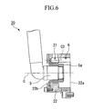
- FIG. 6 is a sectional view of the position corresponding to the section A-A in FIG 1A, showing the burner for combustion chamber according to the second embodiment of the present invention.
- A first embodiment of the present invention will be described below with reference to FIGS. 1A to 3.
- As shown in FIGS. 1A, 1B, and 1C, a
burner 1 for combustion chamber according to the first embodiment of the present invention is provided with the following: acylindrical mixing portion 3 that mixes air for combustion (oxidizing agent) and fuel in the interior thereof, with oneend 3 a opening to acombustion portion 2; a spray nozzle (fuel spraying portion) 5 that sprays fuel in themixing portion 3, being disposed on anotherend 3b of themixing portion 3; a plurality of first blowingports 6 that introduce the air for combustion to themixing portion 3 to form a swirling flow with the fuel, being disposed to open to the inner wall of themixing portion 3; and a plurality ofsecond blowing ports 7 that additionally introduce the air for combustion to themixing portion 3, opening in a direction different from the flow of the swirling flow and being disposed further to theother end 3b side of themixing portion 3 than thefirst blowing ports 6. - The inner diameter of the
mixing portion 3 is formed to be smaller than the inner diameter of thecombustion portion 2. - As shown in FIGS. 2A, 2B, and 3, the first blowing
ports 6 are provided in a direction perpendicular to the central axis C of themixing portion 3 and, by obliquely penetrating the wall surface of themixing portion 3 while sloping in the radial direction with respect to the circumferential direction of themixing portion 3, open to the interior of themixing portion 3. The first blowingports 6 are equally spaced in the circumferential direction of themixing portion 3. - As shown in FIG. 2A, each of the
second blowing ports 7 is provided extending along a central axis C2 which is parallel to the central axis C. The second blowingports 7 are equally spaced from each other on same periphery of a circle around the central axis C of themixing portion 3. The second blowingports 7 are further to the inside of thefirst blowing ports 6 in the radial direction of themixing portion 3, being disposed one-for-one for each first blowingport 6 at a position where the central axis C2 of the second blowing port intersects the central axis C1 of the first blowingport 6. The second blowingports 7 are formed to open at both the oneend 3a and theother end 3b of themixing portion 3. - Next, the combustion method of the
burner 1 for combustion chamber according to the present embodiment and the action and effect thereof will be described. - First, air for combustion is introduced from the first blowing
ports 6 and the second blowingports 7 into themixing portion 3, and fuel in a spray form is injected into themixing portion 3 from thespray nozzle 5. - At this time, the air for combustion that is introduced from the first blowing
ports 6 flows across the inner wall surface of themixing portion 3 in both a circumferential direction and an inward radial direction, so that a strong swirling flow is formed in themixing portion 3. However, the air for combustion that is introduced from the second blowingports 7 flows toward thecombustion portion 2 in parallel with the central axis C to collide with the strong swirling flow. At this time, the strong swirling flow is partially destroyed to cause a vortex breakdown, with large turbulence being generated on the downstream side. - At this time, the mixture of the air for combustion and the fuel is rapidly performed by this large turbulence to produce a lean mixture that moves to the
combustion portion 2. Here, since the swirling flow is not completely destroyed, the lean mixture abruptly expands in diameter in thecombustion portion 2. Thus, the lean mixture comes to have a wide flammable zone, so that a large flame 8 is generated by ignition. - The
burner 1 for combustion chamber and this combustion method can form a stronger turbulence state than in the case of forming only a strong swirling flow in the mixing portion, and therefore can rapidly accelerate the mixing of the fuel and the air for combustion. At this juncture, the flammable zone in thecombustion portion 2 that is disposed downstream of the oneend 3a of the mixingportion 3 can be greatly expanded in the diameter direction by the moderate swirling that remains and the large turbulence. Accordingly, it is possible to shorten the distance between thecombustion portion 2 and the mixingportion 3. - By raising the combustion efficiency, the flame length in the mixing
portion 3 can be shortened in the direction of the central axis C, and the overall length of theburner 1 for combustion chamber can be shortened in the direction of the central axis C. - Since the
first blowing ports 6 and thesecond blowing ports 7 open in directions that mutually intersect, when the air for combustion is introduced from both, it is possible to form a lean mixture having large turbulence in the mixingportion 3 and possible to quickly move the lean mixture to thecombustion portion 2. Accordingly, occurrences of back firing and self ignition in the mixingportion 3 can be suitably inhibited. - Next, a second embodiment shall be described with reference to FIGS. 4A and 4B.
- In this embodiment, constituent elements identical to those in the first embodiment are identified with the same reference numbers, with explanations thereof omitted.
- As shown in FIG 4A, the point of difference of the second embodiment and the first embodiment is that a
distal end 5a of thespray nozzle 5 in aburner 10 for combustion chamber according to the present embodiment is disposed projecting from anotherend 11b to the side of adistal end 11a of a mixing portion 11 along the central axis C until the disposed position of thefirst blowing ports 6. - The combustion method of this
burner 10 for combustion chamber and the action and effect thereof shall be described. - First, air for combustion is introduced from the
first blowing ports 6 and thesecond blowing ports 7 into the mixing portion 11, and fuel in a spray form is injected into the mixing portion 11 from thespray nozzle 5. - At this time, the strong swirling flow due to the air for combustion that is introduced from the
first blowing ports 6 collides with thedistal end 5a of thespray nozzle 5, so that a strong shear layer is produced in the mixing portion 11. - Since the air for combustion that is introduced from the
second blowing ports 7 collides with this shear flow and the strong swirling flow due to the air for combustion that is introduced from thefirst blowing ports 6, greater turbulence is produced downstream of thefirst blowing ports 6 than in the first embodiment. - Thus, the mixture of the air for combustion and the fuel is rapidly performed. At this time, since the swirling flow is not completely destroyed similarly to the first embodiment, the lean mixture abruptly expands in diameter in the
combustion portion 2. - The
burner 10 for combustion chamber and the combustion method of this embodiment can more rapidly mix the fuel and the air for combustion than theburner 1 for combustion chamber and the combustion method of the first embodiment by more extensively destroying the strong swirling flow, and can more stably perform ignition at low temperatures and at low loads. - Next, a third embodiment will be described with reference to FIGS. 5A and 5B.
- In this embodiment, constituent elements identical to those in the other embodiments described above are identified with the same reference numbers, with explanations thereof omitted.
- As shown in FIG 5B, the point of difference of the third embodiment and the second embodiment is that a
second blowing port 16 of aburner 15 for combustion chamber according to the present embodiment is formed as a circular slit. - The width of this second blowing
port 16 is approximately the same as the inner diameter of thesecond blowing ports 7 according to the first and second embodiments, and is provided in a manner that makes thesecond blowing ports 7 continuous in the circumferential direction. - The outside diameter of a spray nozzle 17 is formed to be of a smaller diameter than the
spray nozzle 5 according to the first and second embodiments, and the outside diameter of a mixingportion 18 is formed to be of a smaller diameter than the mixingportion 3 of the first embodiment and the mixing portion 11 of the second embodiment. - The
burner 15 for combustion chamber can exhibit the same action and effect as the aforedescribed other embodiments. In particular, since the second blowingport 16 has a greater capacity than thesecond blowing ports 7 of the other embodiments, the flow rate of the air for combustion that is introduced to the mixingportion 18 can be made greater than in the other embodiments, and the flow distribution of the flow in the axial direction can be made greater than the flow in the radial direction. Accordingly, the outside diameter of the spray nozzle 17 and the mixingportion 18 can be reduced to achieve a reduction in weight. - While preferred embodiments of the invention have been described and illustrated above, it should be understood that these are exemplary of the invention and are not to be considered as limiting. Additions, omissions, substitutions, and other modifications can be made without departing from the spirit or scope of the present invention. Accordingly, the invention is not to be considered as being limited by the foregoing description, and is only limited by the scope of the appended claims. For example, the
distal end 5a of thespray nozzle 5 is not restricted to the aforedescribed embodiments, so long as it is at a position that produces a collision with the air for combustion that is introduced from thefirst blowing ports 6. - Also, as shown in FIG. 6, a
second blowing port 21 of aburner 20 for combustion chamber, in addition to opening to oneend 22a of a mixingportion 22, may be made to open to the outer circumferential surface of the mixingportion 22 instead of the side of theother end 22b. In this case, a mixing portion can be made taking into consideration the stress release of thespray nozzle 5. - In addition, the size of the second blowing port may be adjustable, with the second blowing port not having a central axis that is parallel to the central axis C but instead being formed to slope so as to have a central axis that intersects the central axis C at a predetermined angle.
- When confirming the combustion efficiencies of the conventional burner for combustion chamber and the
burner 10 for combustion chamber according to the second embodiment by actual combustion, the area of the flame generated in thecombustion portion 2 could be expanded approximately three times with respect to the diameter in the visible region. Also, the length of the flame was reduced along the central axis of the burner and the combustion efficiency could be enhanced several percent accordingly.
Claims (4)
- A burner for combustion chamber comprising:a cylindrical mixing portion that mixes an oxidizing agent and fuel in the interior thereof, with one end opening to a combustion portion;a fuel spraying portion that sprays fuel in the mixing portion, being disposed on another end of the mixing portion;first blowing ports that introduce the oxidizing agent to the mixing portion to form a swirling flow with the fuel, being disposed to open to the inner wall of the mixing portion; andsecond blowing ports that additionally introduce the oxidizing agent to the mixing portion, opening in a direction different from the first blowing ports and being disposed further to the other end side of the mixing portion than the swirling flow.
- The burner for combustion chamber according to claim 1, wherein:the first blowing ports open in the circumferential direction of the mixing portion; andthe second blowing ports are provided to open in the central axial direction of the mixing portion, and are disposed further to the inside of the first blowing ports in the radial direction of the mixing portion.
- The burner for combustion chamber according to claim 1, wherein:the distal end of the fuel spraying portion is disposed projecting to the position of the first blowing ports along the central axis of the mixing portion.
- A combustion method comprising the steps of:forming a swirling flow in a cylindrical mixing portion in which one end opens to a combustion portion, by mixing fuel that is sprayed from the other end side into the mixing portion and an oxidizing agent that is introduced into the interior of the mixing portion from a wall surface thereof, andadditionally introducing the oxidizing agent into the mixing portion in a direction different from the swirling flow and from further to the other end side of the mixing portion than the swirling flow.
Applications Claiming Priority (1)
| Application Number | Priority Date | Filing Date | Title |
|---|---|---|---|
| JP2006080881A JP5023526B2 (en) | 2006-03-23 | 2006-03-23 | Combustor burner and combustion method |
Publications (3)
| Publication Number | Publication Date |
|---|---|
| EP1837597A2 true EP1837597A2 (en) | 2007-09-26 |
| EP1837597A3 EP1837597A3 (en) | 2010-12-15 |
| EP1837597B1 EP1837597B1 (en) | 2012-05-23 |
Family
ID=38134885
Family Applications (1)
| Application Number | Title | Priority Date | Filing Date |
|---|---|---|---|
| EP07251103A Active EP1837597B1 (en) | 2006-03-23 | 2007-03-15 | Burner for combustion chamber and combustion method |
Country Status (4)
| Country | Link |
|---|---|
| US (1) | US7913494B2 (en) |
| EP (1) | EP1837597B1 (en) |
| JP (1) | JP5023526B2 (en) |
| CA (1) | CA2581429C (en) |
Cited By (3)
| Publication number | Priority date | Publication date | Assignee | Title |
|---|---|---|---|---|
| CN103807869A (en) * | 2012-11-08 | 2014-05-21 | 烟台龙源电力技术股份有限公司 | Over firing air nozzle for boiler and boiler |
| EP2743581A1 (en) | 2012-12-11 | 2014-06-18 | Siemens Aktiengesellschaft | Air directed fuel injection |
| CN106594802A (en) * | 2016-11-29 | 2017-04-26 | 同济大学 | Double swirl lean premixing spray nozzle and application thereof |
Families Citing this family (22)
| Publication number | Priority date | Publication date | Assignee | Title |
|---|---|---|---|---|
| EP1852657A4 (en) * | 2005-02-25 | 2012-02-29 | Ihi Corp | Fuel injection valve, combustor using the fuel injection valve, and fuel injection method for the fuel injection valve |
| US20080268387A1 (en) * | 2007-04-26 | 2008-10-30 | Takeo Saito | Combustion equipment and burner combustion method |
| KR100886190B1 (en) * | 2007-11-12 | 2009-02-27 | 한국에너지기술연구원 | Burner for exhaust gas reducing atmosphere composition of engine cogeneration plant with denitrification process |
| JP5176695B2 (en) * | 2008-05-30 | 2013-04-03 | 株式会社Ihi | Burner |
| US8616193B2 (en) * | 2008-06-27 | 2013-12-31 | Electrolux Home Products, Inc. | Cooktop swirl burner |
| MX2011003817A (en) * | 2008-10-09 | 2011-08-03 | Suarez Rene Mauricio Nunez | Device for generating and transmitting heat capable of operating with fuel in any physical state and combustion flame. |
| US8561602B2 (en) | 2008-12-24 | 2013-10-22 | Agio International Company, Ltd. | Gas feature and method |
| JP5716313B2 (en) * | 2010-08-05 | 2015-05-13 | 株式会社Ihi | Burner |
| JP5821545B2 (en) * | 2011-11-08 | 2015-11-24 | 株式会社Ihi | Burner and combustor |
| DE102012002664A1 (en) * | 2012-02-10 | 2013-08-14 | Rolls-Royce Deutschland Ltd & Co Kg | Gasturbinenvormischbrenner |
| JP2013178003A (en) * | 2012-02-28 | 2013-09-09 | Ihi Corp | Burner and gas turbine combustor with the same |
| JP5991025B2 (en) * | 2012-05-22 | 2016-09-14 | 株式会社Ihi | Burner and gas turbine combustor |
| EP2685160B1 (en) * | 2012-07-10 | 2018-02-21 | Ansaldo Energia Switzerland AG | Premix burner of the multi-cone type for a gas turbine |
| US9791156B2 (en) * | 2014-07-30 | 2017-10-17 | Haier Us Appliance Solutions, Inc. | Elongated burner assembly |
| US10584639B2 (en) * | 2014-08-18 | 2020-03-10 | Woodward, Inc. | Torch igniter |
| JP6602004B2 (en) * | 2014-09-29 | 2019-11-06 | 川崎重工業株式会社 | Fuel injector and gas turbine |
| US10222070B2 (en) * | 2016-01-15 | 2019-03-05 | Haier Us Appliance Solutions, Inc. | Gas burner assembly with a temperature sensor |
| KR20190046219A (en) * | 2017-10-25 | 2019-05-07 | 한화에어로스페이스 주식회사 | Swirler assembly |
| DE102018125848A1 (en) * | 2018-10-18 | 2020-04-23 | Man Energy Solutions Se | Combustion chamber of a gas turbine, gas turbine and method for operating the same |
| US11421601B2 (en) | 2019-03-28 | 2022-08-23 | Woodward, Inc. | Second stage combustion for igniter |
| US12305578B2 (en) | 2020-06-23 | 2025-05-20 | Woodward, Inc. | Ignition system for power generation engine |
| CN217402664U (en) * | 2022-04-13 | 2022-09-09 | 常州市康莱达机电有限公司 | Rotary air inlet mechanism and gas warmer |
Family Cites Families (36)
| Publication number | Priority date | Publication date | Assignee | Title |
|---|---|---|---|---|
| US3605405A (en) * | 1970-04-09 | 1971-09-20 | Gen Electric | Carbon elimination and cooling improvement to scroll type combustors |
| US3703259A (en) * | 1971-05-03 | 1972-11-21 | Gen Electric | Air blast fuel atomizer |
| US3972182A (en) * | 1973-09-10 | 1976-08-03 | General Electric Company | Fuel injection apparatus |
| US3946552A (en) * | 1973-09-10 | 1976-03-30 | General Electric Company | Fuel injection apparatus |
| FR2269646B1 (en) * | 1974-04-30 | 1976-12-17 | Snecma | |
| US4364522A (en) * | 1980-07-21 | 1982-12-21 | General Motors Corporation | High intensity air blast fuel nozzle |
| CA1167369A (en) | 1982-01-28 | 1984-05-15 | Gordon W. Ellis | Oil burner head |
| US5123248A (en) * | 1990-03-28 | 1992-06-23 | General Electric Company | Low emissions combustor |
| DE4110507C2 (en) * | 1991-03-30 | 1994-04-07 | Mtu Muenchen Gmbh | Burner for gas turbine engines with at least one swirl device which can be regulated in a load-dependent manner for the supply of combustion air |
| JP3503172B2 (en) * | 1993-03-01 | 2004-03-02 | 株式会社日立製作所 | Combustor and operating method thereof |
| US5394688A (en) * | 1993-10-27 | 1995-03-07 | Westinghouse Electric Corporation | Gas turbine combustor swirl vane arrangement |
| US5444982A (en) * | 1994-01-12 | 1995-08-29 | General Electric Company | Cyclonic prechamber with a centerbody |
| EP0728989B1 (en) | 1995-01-13 | 2001-11-28 | European Gas Turbines Limited | Gas turbine engine combustor |
| US5623827A (en) * | 1995-01-26 | 1997-04-29 | General Electric Company | Regenerative cooled dome assembly for a gas turbine engine combustor |
| GB2299399A (en) * | 1995-03-25 | 1996-10-02 | Rolls Royce Plc | Variable geometry air-fuel injector |
| GB2316161A (en) * | 1996-08-05 | 1998-02-18 | Boc Group Plc | Oxygen-fuel swirl burner |
| FR2752917B1 (en) * | 1996-09-05 | 1998-10-02 | Snecma | ADVANCED HOMOGENIZATION INJECTION SYSTEM |
| FR2753779B1 (en) | 1996-09-26 | 1998-10-16 | AERODYNAMIC INJECTION SYSTEM FOR A FUEL AIR MIXTURE | |
| US6571559B1 (en) * | 1998-04-03 | 2003-06-03 | General Electric Company | Anti-carboning fuel-air mixer for a gas turbine engine combustor |
| US6082113A (en) * | 1998-05-22 | 2000-07-04 | Pratt & Whitney Canada Corp. | Gas turbine fuel injector |
| JP2001263608A (en) * | 2000-03-22 | 2001-09-26 | Nippon Sanso Corp | Oxygen-enriched liquid fuel burner |
| US6367262B1 (en) * | 2000-09-29 | 2002-04-09 | General Electric Company | Multiple annular swirler |
| JP4079623B2 (en) * | 2001-11-13 | 2008-04-23 | 富士通テン株式会社 | Radar ranging device |
| FR2832493B1 (en) | 2001-11-21 | 2004-07-09 | Snecma Moteurs | MULTI-STAGE INJECTION SYSTEM OF AN AIR / FUEL MIXTURE IN A TURBOMACHINE COMBUSTION CHAMBER |
| US6834505B2 (en) * | 2002-10-07 | 2004-12-28 | General Electric Company | Hybrid swirler |
| JP3901663B2 (en) | 2003-05-13 | 2007-04-04 | 石川島播磨重工業株式会社 | Rapid fuel injection valve and low NOx combustor |
| JP3940705B2 (en) * | 2003-06-19 | 2007-07-04 | 株式会社日立製作所 | Gas turbine combustor and fuel supply method thereof |
| JP3901673B2 (en) * | 2003-09-01 | 2007-04-04 | 石川島播磨重工業株式会社 | Low NOx injection valve for liquid fuel and fuel injection method thereof |
| FR2859272B1 (en) * | 2003-09-02 | 2005-10-14 | Snecma Moteurs | AIR / FUEL INJECTION SYSTEM IN A TURBOMACHINE COMBUSTION CHAMBER HAVING MEANS FOR GENERATING COLD PLASMA |
| US6983599B2 (en) * | 2004-02-12 | 2006-01-10 | General Electric Company | Combustor member and method for making a combustor assembly |
| US7334410B2 (en) * | 2004-04-07 | 2008-02-26 | United Technologies Corporation | Swirler |
| US7013649B2 (en) * | 2004-05-25 | 2006-03-21 | General Electric Company | Gas turbine engine combustor mixer |
| US7059135B2 (en) * | 2004-08-30 | 2006-06-13 | General Electric Company | Method to decrease combustor emissions |
| JP4626251B2 (en) * | 2004-10-06 | 2011-02-02 | 株式会社日立製作所 | Combustor and combustion method of combustor |
| FR2911667B1 (en) * | 2007-01-23 | 2009-10-02 | Snecma Sa | FUEL INJECTION SYSTEM WITH DOUBLE INJECTOR. |
| DE102008014744A1 (en) * | 2008-03-18 | 2009-09-24 | Rolls-Royce Deutschland Ltd & Co Kg | Gas turbine burner for a gas turbine with a rinsing mechanism for a fuel nozzle |
-
2006
- 2006-03-23 JP JP2006080881A patent/JP5023526B2/en not_active Expired - Lifetime
-
2007
- 2007-03-08 US US11/683,614 patent/US7913494B2/en active Active
- 2007-03-12 CA CA2581429A patent/CA2581429C/en active Active
- 2007-03-15 EP EP07251103A patent/EP1837597B1/en active Active
Cited By (6)
| Publication number | Priority date | Publication date | Assignee | Title |
|---|---|---|---|---|
| CN103807869A (en) * | 2012-11-08 | 2014-05-21 | 烟台龙源电力技术股份有限公司 | Over firing air nozzle for boiler and boiler |
| CN103807869B (en) * | 2012-11-08 | 2016-03-30 | 烟台龙源电力技术股份有限公司 | A kind of fire air nozzle for boiler and boiler |
| EP2743581A1 (en) | 2012-12-11 | 2014-06-18 | Siemens Aktiengesellschaft | Air directed fuel injection |
| US9835335B2 (en) | 2012-12-11 | 2017-12-05 | Siemens Aktiengesellschaft | Air directed fuel injection |
| CN106594802A (en) * | 2016-11-29 | 2017-04-26 | 同济大学 | Double swirl lean premixing spray nozzle and application thereof |
| CN106594802B (en) * | 2016-11-29 | 2019-02-01 | 同济大学 | A kind of poor premixing nozzle of double-cyclone and its application |
Also Published As
| Publication number | Publication date |
|---|---|
| EP1837597B1 (en) | 2012-05-23 |
| EP1837597A3 (en) | 2010-12-15 |
| CA2581429A1 (en) | 2007-09-23 |
| US7913494B2 (en) | 2011-03-29 |
| US20070224562A1 (en) | 2007-09-27 |
| CA2581429C (en) | 2010-08-17 |
| JP5023526B2 (en) | 2012-09-12 |
| JP2007255795A (en) | 2007-10-04 |
Similar Documents
| Publication | Publication Date | Title |
|---|---|---|
| US7913494B2 (en) | Burner for combustion chamber and combustion method | |
| EP2824308B1 (en) | Exhaust mixer with offset lobes | |
| EP3059497A2 (en) | Enhanced turbulent mixing | |
| KR20190084904A (en) | Jet swirl air blast fuel injector for gas turbine engine | |
| JP5084626B2 (en) | Turbomachine combustion chamber using spiral air flow | |
| EP2840316B1 (en) | Airblast fuel injector | |
| KR101764039B1 (en) | Fuel spray nozzle | |
| US6901756B2 (en) | Device for the injection of fuel into the flow wake of swirler vanes | |
| JP3944609B2 (en) | Fuel nozzle | |
| US20120023951A1 (en) | Fuel nozzle with air admission shroud | |
| JP5372814B2 (en) | Gas turbine combustor and operation method | |
| EP2587037A2 (en) | Turbofan engine mixer assembly | |
| JP4894295B2 (en) | Combustion device, combustion method of combustion device, and modification method of combustion device | |
| US6415598B2 (en) | Exhaust nozzle for by-pass gas turbine engines | |
| US20160258627A1 (en) | Low net-swirl configurations for gas turbine engine combustors | |
| JP2020522644A (en) | Flight vehicle air breathing propulsion system with an isolator with obstacles | |
| EP2547959B1 (en) | Swirled fuel injection | |
| JP2016035358A (en) | Premixing burner | |
| US9541293B2 (en) | Reheat burner and method of mixing fuel/carrier air flow within a reheat burner | |
| JP5176695B2 (en) | Burner | |
| EP2997309B1 (en) | Acoustic damping system for a combustor of a gas turbine engine | |
| JP2007120333A (en) | Injection pipe of combustor for rocket and combustor for rocket | |
| KR101852006B1 (en) | The shape of inner passage of vane | |
| JP5716313B2 (en) | Burner | |
| JP2005226849A (en) | Gas turbine combustor and its combustion air supply method |
Legal Events
| Date | Code | Title | Description |
|---|---|---|---|
| PUAI | Public reference made under article 153(3) epc to a published international application that has entered the european phase |
Free format text: ORIGINAL CODE: 0009012 |
|
| 17P | Request for examination filed |
Effective date: 20070323 |
|
| AK | Designated contracting states |
Kind code of ref document: A2 Designated state(s): AT BE BG CH CY CZ DE DK EE ES FI FR GB GR HU IE IS IT LI LT LU LV MC MT NL PL PT RO SE SI SK TR |
|
| AX | Request for extension of the european patent |
Extension state: AL BA HR MK YU |
|
| RAP1 | Party data changed (applicant data changed or rights of an application transferred) |
Owner name: IHI CORPORATION |
|
| PUAL | Search report despatched |
Free format text: ORIGINAL CODE: 0009013 |
|
| AK | Designated contracting states |
Kind code of ref document: A3 Designated state(s): AT BE BG CH CY CZ DE DK EE ES FI FR GB GR HU IE IS IT LI LT LU LV MC MT NL PL PT RO SE SI SK TR |
|
| AX | Request for extension of the european patent |
Extension state: AL BA HR MK RS |
|
| AKX | Designation fees paid |
Designated state(s): FR GB |
|
| REG | Reference to a national code |
Ref country code: DE Ref legal event code: R108 |
|
| REG | Reference to a national code |
Ref country code: DE Ref legal event code: R108 Effective date: 20110824 |
|
| GRAC | Information related to communication of intention to grant a patent modified |
Free format text: ORIGINAL CODE: EPIDOSCIGR1 |
|
| GRAP | Despatch of communication of intention to grant a patent |
Free format text: ORIGINAL CODE: EPIDOSNIGR1 |
|
| RIN1 | Information on inventor provided before grant (corrected) |
Inventor name: SAITOU, TSUKASAC/O IHI CORPORATION Inventor name: RIECHELMANN, DIRKC/O IHI CORPORATION Inventor name: HIROMITSU, NAGAYOSHIC/O IHI CORPORATION Inventor name: HOSOI, JUNC/O IHI CORPORATION Inventor name: SATO, JUNICHIC/O IHI CORPORATION Inventor name: FUJII, ATSUSHIC/O IHI CORPORATION |
|
| GRAS | Grant fee paid |
Free format text: ORIGINAL CODE: EPIDOSNIGR3 |
|
| GRAA | (expected) grant |
Free format text: ORIGINAL CODE: 0009210 |
|
| AK | Designated contracting states |
Kind code of ref document: B1 Designated state(s): FR GB |
|
| REG | Reference to a national code |
Ref country code: GB Ref legal event code: FG4D |
|
| PLBE | No opposition filed within time limit |
Free format text: ORIGINAL CODE: 0009261 |
|
| STAA | Information on the status of an ep patent application or granted ep patent |
Free format text: STATUS: NO OPPOSITION FILED WITHIN TIME LIMIT |
|
| 26N | No opposition filed |
Effective date: 20130226 |
|
| REG | Reference to a national code |
Ref country code: FR Ref legal event code: PLFP Year of fee payment: 10 |
|
| REG | Reference to a national code |
Ref country code: FR Ref legal event code: PLFP Year of fee payment: 11 |
|
| REG | Reference to a national code |
Ref country code: FR Ref legal event code: PLFP Year of fee payment: 12 |
|
| PGFP | Annual fee paid to national office [announced via postgrant information from national office to epo] |
Ref country code: GB Payment date: 20260202 Year of fee payment: 20 |
|
| PGFP | Annual fee paid to national office [announced via postgrant information from national office to epo] |
Ref country code: FR Payment date: 20260209 Year of fee payment: 20 |