EP1837506B1 - Method for monitoring thrust in gas turbine engines - Google Patents
Method for monitoring thrust in gas turbine engines Download PDFInfo
- Publication number
- EP1837506B1 EP1837506B1 EP07250795.7A EP07250795A EP1837506B1 EP 1837506 B1 EP1837506 B1 EP 1837506B1 EP 07250795 A EP07250795 A EP 07250795A EP 1837506 B1 EP1837506 B1 EP 1837506B1
- Authority
- EP
- European Patent Office
- Prior art keywords
- engine
- gas turbine
- difference
- predetermined
- thrust
- Prior art date
- Legal status (The legal status is an assumption and is not a legal conclusion. Google has not performed a legal analysis and makes no representation as to the accuracy of the status listed.)
- Expired - Fee Related
Links
Images

Classifications
-
- F—MECHANICAL ENGINEERING; LIGHTING; HEATING; WEAPONS; BLASTING
- F01—MACHINES OR ENGINES IN GENERAL; ENGINE PLANTS IN GENERAL; STEAM ENGINES
- F01D—NON-POSITIVE DISPLACEMENT MACHINES OR ENGINES, e.g. STEAM TURBINES
- F01D21/00—Shutting-down of machines or engines, e.g. in emergency; Regulating, controlling, or safety means not otherwise provided for
- F01D21/003—Arrangements for testing or measuring
-
- F—MECHANICAL ENGINEERING; LIGHTING; HEATING; WEAPONS; BLASTING
- F02—COMBUSTION ENGINES; HOT-GAS OR COMBUSTION-PRODUCT ENGINE PLANTS
- F02C—GAS-TURBINE PLANTS; AIR INTAKES FOR JET-PROPULSION PLANTS; CONTROLLING FUEL SUPPLY IN AIR-BREATHING JET-PROPULSION PLANTS
- F02C9/00—Controlling gas-turbine plants; Controlling fuel supply in air- breathing jet-propulsion plants
-
- F—MECHANICAL ENGINEERING; LIGHTING; HEATING; WEAPONS; BLASTING
- F05—INDEXING SCHEMES RELATING TO ENGINES OR PUMPS IN VARIOUS SUBCLASSES OF CLASSES F01-F04
- F05D—INDEXING SCHEME FOR ASPECTS RELATING TO NON-POSITIVE-DISPLACEMENT MACHINES OR ENGINES, GAS-TURBINES OR JET-PROPULSION PLANTS
- F05D2260/00—Function
- F05D2260/80—Diagnostics
-
- F—MECHANICAL ENGINEERING; LIGHTING; HEATING; WEAPONS; BLASTING
- F05—INDEXING SCHEMES RELATING TO ENGINES OR PUMPS IN VARIOUS SUBCLASSES OF CLASSES F01-F04
- F05D—INDEXING SCHEME FOR ASPECTS RELATING TO NON-POSITIVE-DISPLACEMENT MACHINES OR ENGINES, GAS-TURBINES OR JET-PROPULSION PLANTS
- F05D2270/00—Control
- F05D2270/01—Purpose of the control system
- F05D2270/05—Purpose of the control system to affect the output of the engine
Definitions
- the present invention relates to monitoring gas turbine engines, and in particular relates to monitoring the thrust produced by gas turbine engines.
- the present invention seeks to provide a system which can overcome these disadvantages.
- US3736796 discloses a warning signal generated if a high bypass ratio fan-type gas turbine engine fails to develop adequate thrust for takeoff of an aircraft. Two engine operating parameters are derived, referred compressor speed and referred fan speed. After a takeoff is initiated, a warning signal is developed under any one of three conditions: (1) if the referred compressor speed is less than a pre-established reference level; (2) if the referred fan speed is less than a pre-established reference level; and (3) if the ratio of compressor speed to fan speed is less than a pre-established reference level.
- a method of providing an indication of the thrust available from a gas turbine engine on an aircraft on the ground comprising:
- Such a method can further comprise, if the difference is less than a predetermined threshold value, the steps of:
- such measuring steps are carried out only if the engine is operating at maximum power, or within a predetermined range at a high power engine setting. That is to say the engine is set to achieve a desired engine setting which is indicative of the engine condition necessary to achieve take off.
- such measuring steps are carried out only if an engine controller is functioning correctly, and controlling the engine to within a predetermined range at maximum power.
- a gas turbine engine system comprising a gas turbine engine, a controller operable to control the engine, and a monitoring unit operable to perform steps in such a method.
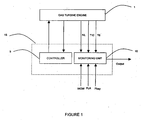
- FIG. 1 is a block diagram illustrating a gas turbine engine 1 and an associated controller 5, and a monitoring unit 10 according to the present invention.
- the control unit 5 and monitoring unit 10 comprise part of an engine control unit 15.
- the controller 5 provides electronic feedback control of the gas turbine engine 1. The nature of this control, the techniques used and the details of all the inputs and outputs necessary for controlling the gas turbine will not be described here for the sake of clarity.
- the monitoring unit 10 operates to provide an indication to the pilot or aircraft control system (for example, for an unmanned air vehicle) that the thrust available from the gas turbine engine is sufficient for the safe operation of the aircraft, within predetermined limits.
- the monitoring unit 10 also monitors the turbine (outlet) temperature T6 of the engine 1, as will be described below.
- the pre-flight check In order that the pre-flight check can be carried out, it must be determined that the aircraft is on the ground, that is that the "weight on wheels” (WOW) condition is true. It is also necessary to determine that the throttle setting (Pilot's Lever Angle, PLA) is on maximum, or within a predetermined amount of maximum for sufficient time for the engine to reach operational temperature. It is also necessary to determine that the engine controller 5 is controlling the engine to maximum or within a predetermined range at a high power engine setting, and that the engine controller is functional.
- WOW weight on wheels
- step A the weight on wheels (WOW) determination is made, in order to confirm that the aircraft is on the ground.
- the aircraft Preferably, the aircraft must have been on the ground for a predetermined time period, such as 30 seconds. If this WOW condition is met, then it is determined whether the pilot's lever angle (the throttle setting) is at maximum or within a predetermined range at a high power engine setting, step B.
- step C it is determined whether the engine controller is controlling the engine to maximum, and at step D it is determined whether the engine controller is functional.
- steps A to D can be carried out in any order, or simultaneously. The only requirement is that all four parameters are checked and that PLA is set to maximum high power setting for a predetermined length of time (for example 2 or 3 seconds while the engine is at maximum high power operating temperature) so that it is clearly established that the right condition to be assessed has been reached.
- the fan aerodynamic speed is given by:
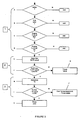
- step F the difference between the actual NLRT value (NLRT actual ) and the expected or required NLRT value (NLRT req ) is determined and compared to a threshold value.
- the tolerance ⁇ NLRT is determined in consideration of engine inlet temperature (T12) and engine bay pressure (PBAY) which is an indicator of altitude. If the difference is greater than this threshold value, then the amount of thrust available from the gas turbine engine is determined as being too low, and a thrust failure indication is made (step G). If, however, the difference is less than the threshold value, then an indication of thrust is made (step K). Alternatively, and as shown in Figure 3 , the process moves to step H in which the turbine outlet temperature T6 is determined.
- step H the turbine outlet temperature T6 is determined (T6 actual ), and at step I is compared with an expected, or limiting, value (T6 limit ). If the difference between these temperature values ( ⁇ T6) is more than a threshold value, then the engine is operating within desired limits for the given day temperature, and an indication that the expected level of thrust is available is given to the pilot (step K). However if the difference is less than the threshold value then a thrust failure indication is made (step J) as such a value of ⁇ T6 is indicative that sufficient temperature margin is not available to achieve required thrust.
- Deteriorated gas turbine engines tend to run at higher temperatures (T6) than non-deteriorated engines. Accordingly, the T6 measurement and comparison is important to give an indication of the presence of a deteriorated engine. In addition, such a deteriorating engine could fail the NLRT check on a hot day due to operation on the T6 limit, but could produce adequate thrust on a cold day. If the NLRT measurement is passed, but the measured T6 level is too close to the T6 limit, then the engine can be considered to be running hotter than expected, which is an indication that adequate thrust will not be available.
- engine running hotter than expected is a symptom of other engine problems, for example a leaking or erroneously open bleed valve, which will be detrimental to the performance of the aircraft.
- the present invention can be employed to identify a plurality of engine problems.
- step H On a hot day (that is to say, ambient air temperature is above a predetermined value), the result of the T6 measurement and comparison (step H) may be ignored if air temperature is sufficient for engine operation on the T6 limit expected during normal operation.
- an allowable engine temperature difference may typically be in the range of 25 to 100°C.
- the threshold levels for NLRT and temperature limits are preferably based on known engine models specific to the type of engine concerned.
- the thresholds relating to NLRT and T6 are set to represent an engine which has run for a number of hours equivalent to a typical overhaul period for a gas turbine engine.
- the thresholds may be set to represent an engine which has run for 4000 hours.
- the pilot may be provided with a cockpit-mounted indicator light that is illuminated (or switched off) when the thrust passed message is determined.
- the thrust failure or acceptance could take the form of a signal sent to a control system to abort or allow take off (for example in an unmanned air vehicle).
- steps F and H are carried out in parallel, hence a negative result in step F will not prevent step H from being executed.
- the monitoring equipment will store and/or display a fault code which indicates which of steps A to K has indicated a fault/error.
- the monitoring equipment will store and/or display a fault code which indicates which group or groups of steps has indicated a fault/error. That is to say, by way of non limiting example, and as shown in Figure 3 , the steps A to K can be divided up in groups such that group “1" comprises steps A to D, group “2" relates to steps E to G and group “3" relates to steps H to J.
- group "1" failure signal will indicate that at least one of steps A to D has identified an error.
Description
- The present invention relates to monitoring gas turbine engines, and in particular relates to monitoring the thrust produced by gas turbine engines.
- Many aircraft make use of one or more gas turbine engines for propulsion. Before take-off, an aircraft's pilot must determine that the available gas turbine engine thrust is sufficient for safe operation of the aircraft. It is also desirable to determine whether an engine is running at a higher temperature than expected, as such "hot" running can indicate deterioration of the engine.
- Currently, pilots are provided with look-up tables of information which must be manually checked before take-off. This is known as a "placard check". Naturally, manually checking has high risk factors, associated with misinterpretation of data and incorrect reading of the lookup tables as well as adding time to the pre-flight check procedure. In addition, such a manual system is unable to adequately compensate for changes in ambient conditions.
- Accordingly, the present invention seeks to provide a system which can overcome these disadvantages.
-
US3736796 discloses a warning signal generated if a high bypass ratio fan-type gas turbine engine fails to develop adequate thrust for takeoff of an aircraft. Two engine operating parameters are derived, referred compressor speed and referred fan speed. After a takeoff is initiated, a warning signal is developed under any one of three conditions: (1) if the referred compressor speed is less than a pre-established reference level; (2) if the referred fan speed is less than a pre-established reference level; and (3) if the ratio of compressor speed to fan speed is less than a pre-established reference level. - According to one aspect of the present invention, there is a method of providing an indication of the thrust available from a gas turbine engine on an aircraft on the ground the method comprising:
- operating the engine within a predetermined power range;
- measuring fan mechanical speed of the engine to produce an actual fan aerodynamic speed for the gas turbine;
- determining a difference between the actual fan aerodynamic speed measurement and an expected fan aerodynamic speed measurement for the engine, and if the difference is less than a predetermined threshold level, indicating that required thrust is available from the gas turbine engine in said predetermined power range.
- Such a method can further comprise, if the difference is less than a predetermined threshold value, the steps of:
- determining a turbine outlet temperature, to produce an actual outlet temperature;
- determining a difference between the actual outlet temperature and a predetermined outlet temperature value,
- and if that difference is greater than a predetermined threshold value, indicating that sufficient temperature margin is available to achieve required thrust.
- When such is used in an aircraft, such measuring steps are carried out only if the aircraft is on the ground.
- Preferably, such measuring steps are carried out only if the engine is operating at maximum power, or within a predetermined range at a high power engine setting. That is to say the engine is set to achieve a desired engine setting which is indicative of the engine condition necessary to achieve take off.
- Preferably, such measuring steps are carried out only if an engine controller is functioning correctly, and controlling the engine to within a predetermined range at maximum power.
- According to another aspect of the present invention, there is provided, a gas turbine engine system, comprising a gas turbine engine, a controller operable to control the engine, and a monitoring unit operable to perform steps in such a method.
-
-
Figure 1 is a schematic block diagram illustrating a gas turbine engine, its associated controller, and a monitoring unit in accordance with one aspect of the present invention; -
Figure 2 is a flow chart illustrating steps in a method embodying another aspect of the present invention; and -
Figure 3 is a flow chart illustrating steps in an alternative method to that presented inFigure 2 . -
Figure 1 is a block diagram illustrating agas turbine engine 1 and an associated controller 5, and amonitoring unit 10 according to the present invention. In the embodiment shown the control unit 5 andmonitoring unit 10 comprise part of anengine control unit 15. As is well known, the controller 5 provides electronic feedback control of thegas turbine engine 1. The nature of this control, the techniques used and the details of all the inputs and outputs necessary for controlling the gas turbine will not be described here for the sake of clarity. - The
monitoring unit 10 operates to provide an indication to the pilot or aircraft control system (for example, for an unmanned air vehicle) that the thrust available from the gas turbine engine is sufficient for the safe operation of the aircraft, within predetermined limits. In order to provide this determination, the monitoring unit measures the mechanical low pressure spool speed (NL) of the gas turbine engine and from this calculates the actual fan aerodynamic speed (NLRT), using NL/√θ, where θ = engine inlet temperature (T12) /standard temperature. - The
monitoring unit 10 also monitors the turbine (outlet) temperature T6 of theengine 1, as will be described below. - In order that the pre-flight check can be carried out, it must be determined that the aircraft is on the ground, that is that the "weight on wheels" (WOW) condition is true. It is also necessary to determine that the throttle setting (Pilot's Lever Angle, PLA) is on maximum, or within a predetermined amount of maximum for sufficient time for the engine to reach operational temperature. It is also necessary to determine that the engine controller 5 is controlling the engine to maximum or within a predetermined range at a high power engine setting, and that the engine controller is functional.
- A method embodying the present invention will now be described with reference to
Figure 2 . At step A, the weight on wheels (WOW) determination is made, in order to confirm that the aircraft is on the ground. Preferably, the aircraft must have been on the ground for a predetermined time period, such as 30 seconds. If this WOW condition is met, then it is determined whether the pilot's lever angle (the throttle setting) is at maximum or within a predetermined range at a high power engine setting, step B. At step C, it is determined whether the engine controller is controlling the engine to maximum, and at step D it is determined whether the engine controller is functional. It will be readily appreciated that steps A to D can be carried out in any order, or simultaneously. The only requirement is that all four parameters are checked and that PLA is set to maximum high power setting for a predetermined length of time (for example 2 or 3 seconds while the engine is at maximum high power operating temperature) so that it is clearly established that the right condition to be assessed has been reached. - Assuming that steps A to D all result in positive answers, then the actual fan aerodynamic speed is determined. The fan aerodynamic speed is given by:
- FAS = NL/√θ- , where θ = engine inlet temperature (T12) / standard temperature and NL is the mechanical low pressure spool speed.
- In step F, the difference between the actual NLRT value (NLRTactual) and the expected or required NLRT value (NLRTreq) is determined and compared to a threshold value. The tolerance (ΔNLRT) is determined in consideration of engine inlet temperature (T12) and engine bay pressure (PBAY) which is an indicator of altitude. If the difference is greater than this threshold value, then the amount of thrust available from the gas turbine engine is determined as being too low, and a thrust failure indication is made (step G). If, however, the difference is less than the threshold value, then an indication of thrust is made (step K). Alternatively, and as shown in
Figure 3 , the process moves to step H in which the turbine outlet temperature T6 is determined. - In step H, the turbine outlet temperature T6 is determined (T6actual), and at step I is compared with an expected, or limiting, value (T6limit). If the difference between these temperature values (ΔT6) is more than a threshold value, then the engine is operating within desired limits for the given day temperature, and an indication that the expected level of thrust is available is given to the pilot (step K). However if the difference is less than the threshold value then a thrust failure indication is made (step J) as such a value of ΔT6 is indicative that sufficient temperature margin is not available to achieve required thrust.
- Deteriorated gas turbine engines tend to run at higher temperatures (T6) than non-deteriorated engines. Accordingly, the T6 measurement and comparison is important to give an indication of the presence of a deteriorated engine. In addition, such a deteriorating engine could fail the NLRT check on a hot day due to operation on the T6 limit, but could produce adequate thrust on a cold day. If the NLRT measurement is passed, but the measured T6 level is too close to the T6 limit, then the engine can be considered to be running hotter than expected, which is an indication that adequate thrust will not be available.
- Additionally, engine running hotter than expected is a symptom of other engine problems, for example a leaking or erroneously open bleed valve, which will be detrimental to the performance of the aircraft. Hence the present invention can be employed to identify a plurality of engine problems.
- On a hot day (that is to say, ambient air temperature is above a predetermined value), the result of the T6 measurement and comparison (step H) may be ignored if air temperature is sufficient for engine operation on the T6 limit expected during normal operation.
- In an application where the engine operating temperature is measured in the Low Pressure Turbine (LPT) or at outlet from the turbine (ie in the jet pipe), an allowable engine temperature difference (ΔT6) may typically be in the range of 25 to 100°C.
- The threshold levels for NLRT and temperature limits are preferably based on known engine models specific to the type of engine concerned.
- In a preferred embodiment, the thresholds relating to NLRT and T6 are set to represent an engine which has run for a number of hours equivalent to a typical overhaul period for a gas turbine engine. For example the thresholds may be set to represent an engine which has run for 4000 hours.
- The pilot may be provided with a cockpit-mounted indicator light that is illuminated (or switched off) when the thrust passed message is determined. Alternatively the thrust failure or acceptance could take the form of a signal sent to a control system to abort or allow take off (for example in an unmanned air vehicle).
- In an alternative embodiment, steps F and H are carried out in parallel, hence a negative result in step F will not prevent step H from being executed.
- The monitoring unit is configured such that the method of the present invention is worked only prior to aircraft take off. That is to say, the thrust indication is only determined when the aircraft is on the ground and when the PLA is set to maximum or within a predetermined range at a high power engine setting. After the engine has reached an assumed operational temperature (typically after about 2-3 secs with WOW=true and throttle at maximum) then the pre-flight check according to the present invention is executed. If sufficient thrust is available, and a "GO" indication has been given to the pilot and/or engine control system, the monitor can be configured to cease to indicate thrust status typically after 3 sees as pre-flight conditions are irrelevant to the operation of the in flight aircraft.
- Additionally, if the monitoring equipment does not return a signal which indicates sufficient thrust is available and/or that the engine is running too hot, then the monitoring equipment will store and/or display a fault code which indicates which of steps A to K has indicated a fault/error. Alternatively the monitoring equipment will store and/or display a fault code which indicates which group or groups of steps has indicated a fault/error. That is to say, by way of non limiting example, and as shown in
Figure 3 , the steps A to K can be divided up in groups such that group "1" comprises steps A to D, group "2" relates to steps E to G and group "3" relates to steps H to J. Thus group "1" failure signal will indicate that at least one of steps A to D has identified an error.
Claims (6)
- A method of providing an indication of thrust available from a gas turbine engine on an aircraft on the ground, the method comprising:operating the gas turbine engine within a predetermined power range;measuring (E) fan mechanical speed of the engine to produce an actual fan aerodynamic speed measurement; characterized in thata difference between the actual fan aerodynamic speed measurement and an expected fan aerodynamic speed measurement for the engine is determined (F); andif the difference is less than a predetermined threshold value, indicating (K) that required thrust is available from the engine in said predetermined power range.
- The method of claim 1, wherein, if the difference is less than a predetermined threshold value, the method further comprises:determining (H) a turbine outlet temperature, to produce an actual outlet temperature;determining (I) a difference between the actual outlet temperature and a predetermined outlet temperature value,and if that difference is greater than a predetermined threshold value, indicating (K) that sufficient temperature margin is available to achieve required thrust.
- The method of claim 1 or 2, for use in an aircraft, wherein such measuring steps are carried out only if the aircraft is on the ground.
- The method of claim 1, 2 or 3, wherein such measuring steps are carried out only if the engine is operating within a predetermined range at maximum power.
- The method of any one of claims 1 to 4, wherein such measuring steps are carried out only if an engine controller is functioning correctly, and controlling the engine to within a predetermined range at maximum power.
- A gas turbine engine system, comprising a gas turbine engine (1), a controller (5) operable to control the engine, and a monitoring unit (10) which performs the method of any one of the preceding claims.
Applications Claiming Priority (2)
| Application Number | Priority Date | Filing Date | Title |
|---|---|---|---|
| GB0606022A GB0606022D0 (en) | 2006-03-24 | 2006-03-24 | Monitoring gas turbine engines |
| GB0701399A GB2436366B (en) | 2006-03-24 | 2007-01-24 | Monitoring gas turbine engines |
Publications (3)
| Publication Number | Publication Date |
|---|---|
| EP1837506A2 EP1837506A2 (en) | 2007-09-26 |
| EP1837506A3 EP1837506A3 (en) | 2012-04-04 |
| EP1837506B1 true EP1837506B1 (en) | 2013-08-28 |
Family
ID=38442234
Family Applications (1)
| Application Number | Title | Priority Date | Filing Date |
|---|---|---|---|
| EP07250795.7A Expired - Fee Related EP1837506B1 (en) | 2006-03-24 | 2007-02-26 | Method for monitoring thrust in gas turbine engines |
Country Status (2)
| Country | Link |
|---|---|
| US (1) | US7762125B2 (en) |
| EP (1) | EP1837506B1 (en) |
Families Citing this family (5)
| Publication number | Priority date | Publication date | Assignee | Title |
|---|---|---|---|---|
| US8381510B2 (en) * | 2009-04-30 | 2013-02-26 | General Electric Company | Method and systems for controlling engine thrust using variable trim |
| US11111814B2 (en) | 2017-12-20 | 2021-09-07 | General Electric Company | Turbine engine operational testing |
| GB201814895D0 (en) | 2018-09-13 | 2018-10-31 | Rolls Royce Plc | An apparatus and a method of measuring the thrust of a geared gas turbine engine |
| US20240060427A1 (en) * | 2022-08-22 | 2024-02-22 | Pratt & Whitney Canada Corp. | Systems and methods for determining gas turbine engine operating margins |
| US20240060426A1 (en) * | 2022-08-22 | 2024-02-22 | Pratt & Whitney Canada Corp. | Systems and methods for determining gas turbine engine operating margins |
Family Cites Families (20)
| Publication number | Priority date | Publication date | Assignee | Title |
|---|---|---|---|---|
| US3678742A (en) * | 1970-10-05 | 1972-07-25 | Trans Sonics Inc | Tolerance checking system |
| US3736796A (en) * | 1972-03-27 | 1973-06-05 | Avco Corp | Fan engine thrust monitor |
| US4136517A (en) * | 1976-07-06 | 1979-01-30 | General Electric Company | Thrust control system for a gas turbine engine |
| US4275557A (en) * | 1978-01-25 | 1981-06-30 | General Electric Company | Method and apparatus for controlling thrust in a gas turbine engine |
| US4215412A (en) | 1978-07-13 | 1980-07-29 | The Boeing Company | Real time performance monitoring of gas turbine engines |
| US4313167A (en) * | 1979-07-27 | 1982-01-26 | General Electric Company | Thrust control system for a gas turbine engine |
| US4787053A (en) | 1981-12-30 | 1988-11-22 | Semco Instruments, Inc. | Comprehensive engine monitor and recorder |
| US4651563A (en) | 1985-10-16 | 1987-03-24 | Sperry Corporation | Jet engine testing apparatus |
| US4954974A (en) * | 1988-12-15 | 1990-09-04 | Howell Instruments, Inc. | Turbine engine fan speed monitor |
| US5622045A (en) | 1995-06-07 | 1997-04-22 | Allison Engine Company, Inc. | System for detecting and accommodating gas turbine engine fan damage |
| US6487490B1 (en) * | 1999-05-26 | 2002-11-26 | General Electric Company | Speed modification system for gas turbine engine to allow trimming of excess |
| US6459963B1 (en) * | 2000-07-31 | 2002-10-01 | General Electric Company | Methods and apparatus for trimming engine control systems |
| US6578794B1 (en) * | 2000-11-28 | 2003-06-17 | General Electric Co. | Methods and systems for jet engine overthrust protection |
| GB0116193D0 (en) * | 2001-07-03 | 2001-08-22 | Rolls Royce Plc | An apparatus and method for detecting a damaged rotary machine aerofoil |
| US6687596B2 (en) * | 2001-08-31 | 2004-02-03 | General Electric Company | Diagnostic method and system for turbine engines |
| RU2255247C1 (en) | 2003-12-01 | 2005-06-27 | Открытое акционерное общество "Авиадвигатель" | Method to protect compressor at unsteady operation of gas- turbine engine |
| US6973396B1 (en) | 2004-05-28 | 2005-12-06 | General Electric Company | Method for developing a unified quality assessment and providing an automated fault diagnostic tool for turbine machine systems and the like |
| US20060212281A1 (en) | 2005-03-21 | 2006-09-21 | Mathews Harry Kirk Jr | System and method for system-specific analysis of turbomachinery |
| US20070260424A1 (en) * | 2006-05-05 | 2007-11-08 | Harold Brown | Methods and apparatus for estimating engine thrust |
| GB2447238B (en) * | 2007-03-07 | 2009-11-18 | Rolls Royce Plc | Method for detecting ice ingestion in a gas turbine engine |
-
2007
- 2007-02-26 EP EP07250795.7A patent/EP1837506B1/en not_active Expired - Fee Related
- 2007-03-07 US US11/714,728 patent/US7762125B2/en not_active Expired - Fee Related
Also Published As
| Publication number | Publication date |
|---|---|
| US7762125B2 (en) | 2010-07-27 |
| EP1837506A2 (en) | 2007-09-26 |
| US20070220897A1 (en) | 2007-09-27 |
| EP1837506A3 (en) | 2012-04-04 |
Similar Documents
| Publication | Publication Date | Title |
|---|---|---|
| GB2436366A (en) | Monitoring Gas Turbine Engines | |
| EP3070562B1 (en) | Gas turbine engine health determination | |
| US11015480B2 (en) | Feed forward load sensing for hybrid electric systems | |
| EP3055210B1 (en) | Method for diagnosing an auxiliary power unit fault | |
| US9815568B2 (en) | Device for monitoring a power transmission system of an aircraft, an aircraft provided with the device, and the method used | |
| US20080275597A1 (en) | Balancing the power of two turboshaft engines of an aircraft | |
| KR20130006382A (en) | Method for detecting whether performance of aircraft components is in the decline period | |
| EP1837506B1 (en) | Method for monitoring thrust in gas turbine engines | |
| US6411869B2 (en) | Power margin indicator for a rotary wing aircraft, particularly a helicopter | |
| US9285292B2 (en) | Method of optimizing the performance of an aircraft, a device, and an aircraft | |
| US9821916B2 (en) | Method and a device for managing a loss of power on a three-engined power plant | |
| US20160318620A1 (en) | Aircraft fuel shutoff interlock | |
| EP3683154B1 (en) | Aircraft maintenance systems and methods | |
| EP4019396A1 (en) | System and method for detecting propeller malfunction | |
| WO2019098881A1 (en) | Method of controlling a deicing system on the air intake of an aircraft gas turbine engine | |
| CA3060153C (en) | Aircraft maintenance systems and methods | |
| RU2306446C1 (en) | Method of control of aircraft power plant | |
| US20180155063A1 (en) | Systems and methods for diagnosing turboshaft engine bleed valves | |
| EP4353599A1 (en) | Diagnostic system and method for monitoring hydraulic pump | |
| JP2024058654A (en) | Diagnostic system and method for monitoring a hydraulic pump - Patents.com | |
| CN116927949A (en) | Aircraft engine temperature sensor icing detection system and method and storage medium | |
| Eccles | Full authority digital electronic fuel control for the Pegasus | |
| Davies | Olympus 593 in Concorde-Maintaining the Electronic Engine Control | |
| Anderson et al. | The Army Aircraft Flight Safety Prediction Model |
Legal Events
| Date | Code | Title | Description |
|---|---|---|---|
| PUAI | Public reference made under article 153(3) epc to a published international application that has entered the european phase |
Free format text: ORIGINAL CODE: 0009012 |
|
| AK | Designated contracting states |
Kind code of ref document: A2 Designated state(s): AT BE BG CH CY CZ DE DK EE ES FI FR GB GR HU IE IS IT LI LT LU LV MC NL PL PT RO SE SI SK TR |
|
| AX | Request for extension of the european patent |
Extension state: AL BA HR MK YU |
|
| PUAL | Search report despatched |
Free format text: ORIGINAL CODE: 0009013 |
|
| AK | Designated contracting states |
Kind code of ref document: A3 Designated state(s): AT BE BG CH CY CZ DE DK EE ES FI FR GB GR HU IE IS IT LI LT LU LV MC NL PL PT RO SE SI SK TR |
|
| AX | Request for extension of the european patent |
Extension state: AL BA HR MK RS |
|
| RIC1 | Information provided on ipc code assigned before grant |
Ipc: F02C 9/00 20060101AFI20120301BHEP Ipc: G05D 1/00 20060101ALI20120301BHEP Ipc: F02C 7/26 20060101ALI20120301BHEP |
|
| 17P | Request for examination filed |
Effective date: 20120919 |
|
| AKX | Designation fees paid |
Designated state(s): DE FR GB |
|
| GRAP | Despatch of communication of intention to grant a patent |
Free format text: ORIGINAL CODE: EPIDOSNIGR1 |
|
| INTG | Intention to grant announced |
Effective date: 20130606 |
|
| GRAS | Grant fee paid |
Free format text: ORIGINAL CODE: EPIDOSNIGR3 |
|
| GRAA | (expected) grant |
Free format text: ORIGINAL CODE: 0009210 |
|
| AK | Designated contracting states |
Kind code of ref document: B1 Designated state(s): DE FR GB |
|
| REG | Reference to a national code |
Ref country code: GB Ref legal event code: FG4D |
|
| REG | Reference to a national code |
Ref country code: DE Ref legal event code: R096 Ref document number: 602007032511 Country of ref document: DE Effective date: 20131024 |
|
| REG | Reference to a national code |
Ref country code: DE Ref legal event code: R097 Ref document number: 602007032511 Country of ref document: DE |
|
| PLBE | No opposition filed within time limit |
Free format text: ORIGINAL CODE: 0009261 |
|
| STAA | Information on the status of an ep patent application or granted ep patent |
Free format text: STATUS: NO OPPOSITION FILED WITHIN TIME LIMIT |
|
| 26N | No opposition filed |
Effective date: 20140530 |
|
| REG | Reference to a national code |
Ref country code: DE Ref legal event code: R097 Ref document number: 602007032511 Country of ref document: DE Effective date: 20140530 |
|
| REG | Reference to a national code |
Ref country code: FR Ref legal event code: PLFP Year of fee payment: 10 |
|
| REG | Reference to a national code |
Ref country code: FR Ref legal event code: PLFP Year of fee payment: 11 |
|
| PGFP | Annual fee paid to national office [announced via postgrant information from national office to epo] |
Ref country code: DE Payment date: 20170227 Year of fee payment: 11 Ref country code: FR Payment date: 20170223 Year of fee payment: 11 |
|
| PGFP | Annual fee paid to national office [announced via postgrant information from national office to epo] |
Ref country code: GB Payment date: 20170227 Year of fee payment: 11 |
|
| REG | Reference to a national code |
Ref country code: FR Ref legal event code: CA Effective date: 20170517 |
|
| REG | Reference to a national code |
Ref country code: DE Ref legal event code: R119 Ref document number: 602007032511 Country of ref document: DE |
|
| GBPC | Gb: european patent ceased through non-payment of renewal fee |
Effective date: 20180226 |
|
| REG | Reference to a national code |
Ref country code: FR Ref legal event code: ST Effective date: 20181031 |
|
| PG25 | Lapsed in a contracting state [announced via postgrant information from national office to epo] |
Ref country code: DE Free format text: LAPSE BECAUSE OF NON-PAYMENT OF DUE FEES Effective date: 20180901 |
|
| PG25 | Lapsed in a contracting state [announced via postgrant information from national office to epo] |
Ref country code: FR Free format text: LAPSE BECAUSE OF NON-PAYMENT OF DUE FEES Effective date: 20180228 Ref country code: GB Free format text: LAPSE BECAUSE OF NON-PAYMENT OF DUE FEES Effective date: 20180226 |