EP1835573A2 - Electric connector - Google Patents
Electric connector Download PDFInfo
- Publication number
- EP1835573A2 EP1835573A2 EP07103526A EP07103526A EP1835573A2 EP 1835573 A2 EP1835573 A2 EP 1835573A2 EP 07103526 A EP07103526 A EP 07103526A EP 07103526 A EP07103526 A EP 07103526A EP 1835573 A2 EP1835573 A2 EP 1835573A2
- Authority
- EP
- European Patent Office
- Prior art keywords
- connector
- housing
- connector body
- operation lever
- cavity
- Prior art date
- Legal status (The legal status is an assumption and is not a legal conclusion. Google has not performed a legal analysis and makes no representation as to the accuracy of the status listed.)
- Granted
Links
Images


Classifications
-
- H—ELECTRICITY
- H01—ELECTRIC ELEMENTS
- H01R—ELECTRICALLY-CONDUCTIVE CONNECTIONS; STRUCTURAL ASSOCIATIONS OF A PLURALITY OF MUTUALLY-INSULATED ELECTRICAL CONNECTING ELEMENTS; COUPLING DEVICES; CURRENT COLLECTORS
- H01R13/00—Details of coupling devices of the kinds covered by groups H01R12/70 or H01R24/00 - H01R33/00
- H01R13/64—Means for preventing incorrect coupling
-
- H—ELECTRICITY
- H01—ELECTRIC ELEMENTS
- H01R—ELECTRICALLY-CONDUCTIVE CONNECTIONS; STRUCTURAL ASSOCIATIONS OF A PLURALITY OF MUTUALLY-INSULATED ELECTRICAL CONNECTING ELEMENTS; COUPLING DEVICES; CURRENT COLLECTORS
- H01R13/00—Details of coupling devices of the kinds covered by groups H01R12/70 or H01R24/00 - H01R33/00
- H01R13/62—Means for facilitating engagement or disengagement of coupling parts or for holding them in engagement
- H01R13/629—Additional means for facilitating engagement or disengagement of coupling parts, e.g. aligning or guiding means, levers, gas pressure electrical locking indicators, manufacturing tolerances
- H01R13/62933—Comprising exclusively pivoting lever
- H01R13/6295—Pivoting lever comprising means indicating incorrect coupling of mating connectors
-
- H—ELECTRICITY
- H01—ELECTRIC ELEMENTS
- H01R—ELECTRICALLY-CONDUCTIVE CONNECTIONS; STRUCTURAL ASSOCIATIONS OF A PLURALITY OF MUTUALLY-INSULATED ELECTRICAL CONNECTING ELEMENTS; COUPLING DEVICES; CURRENT COLLECTORS
- H01R13/00—Details of coupling devices of the kinds covered by groups H01R12/70 or H01R24/00 - H01R33/00
- H01R13/64—Means for preventing incorrect coupling
- H01R13/641—Means for preventing incorrect coupling by indicating incorrect coupling; by indicating correct or full engagement
-
- H—ELECTRICITY
- H01—ELECTRIC ELEMENTS
- H01R—ELECTRICALLY-CONDUCTIVE CONNECTIONS; STRUCTURAL ASSOCIATIONS OF A PLURALITY OF MUTUALLY-INSULATED ELECTRICAL CONNECTING ELEMENTS; COUPLING DEVICES; CURRENT COLLECTORS
- H01R13/00—Details of coupling devices of the kinds covered by groups H01R12/70 or H01R24/00 - H01R33/00
- H01R13/62—Means for facilitating engagement or disengagement of coupling parts or for holding them in engagement
- H01R13/629—Additional means for facilitating engagement or disengagement of coupling parts, e.g. aligning or guiding means, levers, gas pressure electrical locking indicators, manufacturing tolerances
- H01R13/62933—Comprising exclusively pivoting lever
- H01R13/62955—Pivoting lever comprising supplementary/additional locking means
Definitions
- This invention relates to an electric connector having a lock function for locking a connection between the electric connector and another connector by rotating an operation lever.
- Electric connector assemblies in which a pair of connectors is locked by using a lock mechanism having a rack and a pinion have been introduced in many patent documents.
- an electric connector assembly 20 described in the specification of German Utility Model No. 8714016 is shown in Fig. 6.
- the electric connector assembly 20 has the first and the second connectors 21, 22 that are engaged with each other.
- the second connector 22 has an operation lever 23 having a pinion 23a in its housing.
- the operation lever 23 is rotatably connected to the housing with a shaft.
- the first connector 21 has a structure in which a rack 21a is formed in a cavity of its housing.
- the connectors 21, 22 are engaged with each other by the following procedures. First, the second connector 22 is inserted into the cavity of the first connector 21, and the rack 21a and the pinion 23a are engaged with each other. When the operation lever 23 is rotated, the second connector 22 is fully engaged with the first connector 21 inside the cavity 21b of the first connector 21. The connectors 21, 22, are released from each other by rotating the operation lever 23 in the opposite direction. The pair of connectors 21, 22 is anchored by engaging the operation lever 23 at a closed position with a latch, namely, making latch engagement at an end of rotation position. With this configuration, the engagement between the connectors can be quickly performed by only inserting into the other connector and making snap engagement between the connectors. Lever-type electric connector assemblies having the same type of operation levers are introduced in US Patent No. 5833484 and No. 6247966B1 .
- the electric connector assembly described in the specification of US Patent No. 6247966B1 is constructed from a pair of connectors.
- the first connector 25 has a connector body 26 having contacts, and a housing 27 having a cavity 27a and an operation lever 28.
- the size of the cavity 27a is decided so as to be capable of housing the connector body 26.
- the connector body 26 is housed in the cavity 27a of the housing 27.
- a locking projection part 26a formed on a sidewall of the connector body 26 is engaged with a catching part 27b formed in the housing 27 via snap engagement.
- a receptacle of a receptacle-type connector may be engaged with another connector in a condition that the receptacle is not properly housed in a cavity of a connector housing when the receptacle is inserted into the housing. If an operation lever is rotated in the condition that the receptacle is not properly housed in the connector housing, contacts mounted to the receptacle are not properly connected with contacts of the other connector. As a result, abnormal stress may be applied to the contacts and the contacts may be damaged.
- connector assemblies in which a connector housing and a receptacle are engaged via snap engagement such as the connector of US Patent No.
- An objective of the present invention is to provide an electric connector in which connection between a connector body including a contact and a connector housing that houses the connector body is more secure in comparison with related art. Namely, the present invention provides an electric connector having improved reliability and safety.
- Another objective of the present invention is to provide an electric connector that enables achievement of the above objective with simple configurations.
- an electric connector of claim 1 of this application has the following configurations and features.
- the electric connector has a connector body having a contact and a connector housing having a cavity, for housing the connector body, and an operation lever. The connector body is slid into the cavity of the connector housing, and the operation lever is rotated for engagement with another connector.
- the connector housing has a sensing member that is formed in one of sidewalls for detecting an insertion condition of the connector body in the cavity by rising from the sidewall as the connector body is slid into the cavity.
- the operation lever hits the sensing member when the sensing member rises from the sidewall, and therefore, rotation of the operation lever is blocked.
- the sensing member of the electric connector of claim 1 has a resilient piece, a projection, and a well.
- the resilient piece is formed by cutting away a portion of the sidewall of the connector housing.
- the projection is formed on an inner surface of a free end of the resilient piece such that the projection extends inwardly in the cavity.
- the well is formed in a portion of a sidewall of the connector body such that the projection is fitted in. The projection is fitted in the well when the connector body is completely inserted in the cavity of the connector housing.
- the operation lever of the electric connector of claims 1 and 2 has a predetermined length of an arm member, and the arm member hits the sensing member.
- the operation lever of the electric connector of claim 3 has an engagement portion at one end of the arm member. The engagement portion is to be engaged with the other connector.
- the present invention provides the following effects.
- the rotation of the operation lever is blocked when the sensing member rises from the sidewall of the connector housing. Namely, an engagement with the other connector cannot be made in a condition that the connector body is not completely inserted in the connector housing.
- the reliability and the safety of the connector connection are improved.
- the resilient piece of the sensing member is formed by cutting away a portion of the sidewall of the connector housing. Namely, the sensing member is easily formed because an extra part and an assembly process are not required. Moreover, only the well is formed in the sidewall of the connector body. Therefore, the connector body also can be easily formed.
- the arm member of the operation lever hits the sensing member.
- the engagement portion that is engaged with the other connector is formed at one end of the lever member.
- the engagement portion may be a pinion that is interlocked with a rack of the other connector.
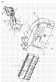
- Fig. 1 is an exploded perspective view of an electric connector 1 according to an embodiment of the present invention.
- Fig. 2 is an exploded perspective view of the electric connector 1 of Fig. 1 without an operation lever 16.
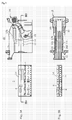
- Figs. 3A and 3B show the electric connector 1 of Fig. 1 viewed from different angles.
- Fig. 3A is a side view
- Fig. 3B is a cross-sectional view of the electric connector 1 sectioned by the IIIB-IIIB line of Fig. 3A.
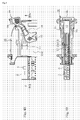
- Figs. 4A and 4B show the electric connector 1 in conditions that a connector body 2 is inserted in a housing.
- Fig. 1 is an exploded perspective view of an electric connector 1 according to an embodiment of the present invention.
- Fig. 2 is an exploded perspective view of the electric connector 1 of Fig. 1 without an operation lever 16.
- Figs. 3A and 3B show the electric connector 1 of Fig. 1 viewed from different angles.
- Fig. 3A is a side view
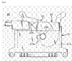
- FIG. 4A is a side view of the electric connector 1 in a condition that the connector body 2 is partially inserted in the housing.
- Fig. 4B is a cross-sectional view of the electric connector 1 sectioned by the IVB-IVB line of Fig. 4A.
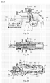
- Figs. 5A, 5B, and 5C show the electric connector 1 in conditions that the connector body 2 is improperly inserted.
- Fig. 5A is a side view
- Fig. 5B is a cross-sectional view of the electric connector 1 sectioned by the VB-VB line of Fig. 5A
- Fig. 5C is a perspective view of the electric connector 1 of Fig. 5A viewed from a different angle.
- the electric connector 1 described below is a receptacle-type connector that is to be engaged with another connector as in the electric connector assembly 20 of the related art although the other connector is not shown in the figures.
- the electric connector 1 includes the connector body 2 and a connector housing (hereafter referred to as housing) 10.
- the connector body 2 has contacts housed in a connector body housing 3.
- the housing 10 has a cavity 12 that is large enough for housing the connector body 2, and an operation lever 16.
- the connector body 2 is inserted in the cavity 12 of the housing 10.
- the overall shape of the connector body 2 is a narrow rectangular parallelepiped shape.
- the connector body 2 has the connector body housing 3 and the contacts (not shown) mounted to the connector body housing 3.
- the connector body housing 3 is made of synthetic resin.
- the connector body housing 3 has an anterior wall 3a, a posterior wall 3b, the first wide sidewall 3c, the second wide sidewall 3d, the first narrow sidewall 3e, and the second narrow sidewall 3f.
- the connector body housing 3 has through holes 4 that run from the anterior wall 3a through the posterior wall 3b.
- the contacts (not shown) are inserted into the through holes 4 and fixed.
- the through holes 4 are arranged in multiple lines at certain intervals in the longitudinal direction of the anterior wall 3a or the posterior wall 3b.
- the second wide sidewall 3d has a hollow race 5 as it approximately divides the second wide sidewall 3d in half in the longitudinal direction. Moreover, the second wide sidewall 3d has a well 6, whose size is predetermined, between the anterior wall 3a and the race 5. The well 6 temporarily holds a small projection 13a of a sensing member 13 formed in the housing 10 as shown in Fig. 3B. It is preferable to provide a mark that indicates an inserting direction to the housing 10, such as an arrow, on a surface of the second wide sidewall 3d.
- the housing 10 is a box-shaped container having a cavity 12, which is large enough for housing the connector body 2, as shown in Figs. 1 and 2.
- the housing 10 includes a narrow anterior wall 11a, a posterior wall (top wall) 11b that opposes the anterior wall 11 a, the first wide sidewall 11c, the second wide sidewall 11d, the first narrow sidewall 11e, and the second narrow sidewall 11f.
- the first narrow sidewall 11e has an opening of the cavity 12.
- the anterior wall 11a has openings 11a' at positions corresponding to the through holes 4 of the connector body 2.
- the anterior wall 11a is a joint surface that is to have contact with the other connector.
- the first wide sidewall 11c and the second wide sidewall 11d have the first axis projection 15 1 and the second axis projection 15 2 , respectively.
- the second axis projection 15 2 is formed on the first wide sidewall 11c, namely, not shown in Figs. 1 and 2.
- the operation lever 16, which will be described later, is attached to the axis projections 15 1 and 15 2 , and rotatably fixed.
- the second wide sidewall 11d has the sensing member 13 about the center.
- the sensing member 13 is a long rectangular piece that extends from the first narrow sidewall 11e to the second narrow sidewall 11f on the second wide sidewall 11d.
- the rectangular piece is formed by producing narrow gaps 14 for defining its edges except for the side adjacent to the first narrow sidewall 11e.
- the sensing member 13 has resilience because it is connected to the second wide sidewall 11d at one end.
- a free end 13b of the sensing member 13 has a small projection 13a, as shown in Fig. 3B.
- the small projection 13a extends from the inner surface of the second wide sidewall 11d for a predetermined length inside the cavity 12.
- the first wide sidewall 11c has a small window 11C 0 at a position corresponding to the sensing member 13 formed on the second wide sidewall 11d.
- the small window 11c 0 is provided for verifying an insertion condition of the connector body 2 by looking at the sidewall of the connector body 2 through the small window 11 c 0 when the connector body 2 is inserted into the housing 10.
- the operation lever 16 is a synthetic resin molding having the first arm 16 1 and the second arm 16 2 .
- One end of the first arm 16 1 and one end of the second arm 16 2 are connected with each other via a connecting member 16 3 .
- the first and the second arms 16 1 , 16 2 have mounting holes 17 1 , 17 2 at their ends, respectively, such that the axis projections 15 1 , 15 2 are inserted into the mounting holes 17 1 , 17 2 .
- the mounting hole 17 2 is formed in the second arm 16 2 and therefore not shown in Fig. 2.
- the first arm 16 1 has a pinion 18 1 at its end.
- the first arm 16 1 has a flat portion 16a on one of the sidewalls that are orthogonal to the second wide sidewall 11d when the operation lever 16 is mounted to the housing 10.
- the pinion 18 1 is engaged with a rack when the electric connector 1 is connected to another connector (not shown). This engagement is made in the same manner as the related art.
- the connecting member 16 3 has a locking member 19 1 for securing the operation lever 16 in a position connected with the other connector and not rotating back to its original position.
- the locking member 19 1 is anchored to locking member 11b' provided in the housing 10.
- FIG. 3 A method for inserting the connector body 2 to the housing 10 will be discussed referring to Figs. 1 through 5C.
- the operation lever 16 is tilted toward the second narrow sidewall 11f, and the connector body 2 in which the contacts are mounted is inserted into the cavity 12 of the housing 10.
- the second wide sidewall 3d of the connector body 2 lifts the small projection 13a of the sensing member 13 as shown in Figs.4A and 4B.
- the free end 13b of the sensing member 13 rises from the surface of the second wide sidewall 11d against the resilience.
- the small projection 13a of the sensing member 13 is fitted into the well 6 of the connector body 2. In this condition, the connector body 2 is completely inserted into the housing 10.
- the operation lever 16 is rotated in this condition, the small projection 13a of the sensing member 13 is fitted in the well 6. Namely, the small projection 13a of the sensing member 13 does not rise from the surface of the second wide sidewall 11d. Therefore, the flat portion 16a of the first arm 16 1 can be rotated without being caught by the sensing member 13.
- the anterior wall 11a of the housing 10 is engaged with the other connector such that the pinion 18 1 of the first arm 16 1 is interlocked with a rack (not shown) of the other connector, the other connector is pulled by the anterior wall 11a and engaged as the operation lever 16 rotates. As a result, connection between the two connector assemblies is properly made.
- the flat portion 16a of the operation lever 16 hits the free end 13b of the sensing member 13 and the rotation is blocked if the free end 13b of the sensing member 13 rises from the surface of the second wide sidewall 11d, namely, the connector body 2 is not completely inserted in the housing 10.
- the electric connector 1 cannot be connected with the other connector if the connector body 2 is incompletely inserted in the housing 10, namely, the reliability and the safety of the connector connection can be maintained at high level.
Landscapes
- Details Of Connecting Devices For Male And Female Coupling (AREA)
Abstract
Description
- This invention relates to an electric connector having a lock function for locking a connection between the electric connector and another connector by rotating an operation lever.
- Electric connector assemblies in which a pair of connectors is locked by using a lock mechanism having a rack and a pinion have been introduced in many patent documents. For example, an
electric connector assembly 20 described in the specification ofGerman Utility Model No. 8714016 is shown in Fig. 6. Theelectric connector assembly 20 has the first and thesecond connectors second connector 22 has anoperation lever 23 having apinion 23a in its housing. Theoperation lever 23 is rotatably connected to the housing with a shaft. Thefirst connector 21 has a structure in which arack 21a is formed in a cavity of its housing. - The
connectors second connector 22 is inserted into the cavity of thefirst connector 21, and therack 21a and thepinion 23a are engaged with each other. When theoperation lever 23 is rotated, thesecond connector 22 is fully engaged with thefirst connector 21 inside thecavity 21b of thefirst connector 21. Theconnectors operation lever 23 in the opposite direction. The pair ofconnectors operation lever 23 at a closed position with a latch, namely, making latch engagement at an end of rotation position. With this configuration, the engagement between the connectors can be quickly performed by only inserting into the other connector and making snap engagement between the connectors. Lever-type electric connector assemblies having the same type of operation levers are introduced inUS Patent No. 5833484 andNo. 6247966B1 . - The electric connector assembly described in the specification of
US Patent No. 6247966B1 is constructed from a pair of connectors. As shown in Fig. 7, thefirst connector 25 has aconnector body 26 having contacts, and ahousing 27 having acavity 27a and anoperation lever 28. The size of thecavity 27a is decided so as to be capable of housing theconnector body 26. Theconnector body 26 is housed in thecavity 27a of thehousing 27. When theconnector body 26 is inserted in thecavity 27a of thehousing 27, alocking projection part 26a formed on a sidewall of theconnector body 26 is engaged with a catchingpart 27b formed in thehousing 27 via snap engagement. - With the above-described configurations, engagement of a pair of connector assemblies is properly made and secured with the operation lever, which reduces accidental release of the engagement. For this reason, these connectors are used in airbag systems of vehicles that require special emphasis on safety and reliability.
- In these electric connector assemblies, however, a receptacle of a receptacle-type connector may be engaged with another connector in a condition that the receptacle is not properly housed in a cavity of a connector housing when the receptacle is inserted into the housing. If an operation lever is rotated in the condition that the receptacle is not properly housed in the connector housing, contacts mounted to the receptacle are not properly connected with contacts of the other connector. As a result, abnormal stress may be applied to the contacts and the contacts may be damaged. In connector assemblies in which a connector housing and a receptacle are engaged via snap engagement, such as the connector of
US Patent No. 6247966B1 , whether the receptacle is properly hosed in the connector housing cannot be confirmed. Moreover, this type of connector is expected to have more emphasis on safety and reliability. If the connector housing and the receptacle are not properly engaged, safety level may be reduced. - In consideration of the above-described related art, the present invention is developed for enhancing safety and improving reliability. An objective of the present invention is to provide an electric connector in which connection between a connector body including a contact and a connector housing that houses the connector body is more secure in comparison with related art. Namely, the present invention provides an electric connector having improved reliability and safety.
- Another objective of the present invention is to provide an electric connector that enables achievement of the above objective with simple configurations.
- To achieve the above objectives, an electric connector of
claim 1 of this application has the following configurations and features. The electric connector has a connector body having a contact and a connector housing having a cavity, for housing the connector body, and an operation lever. The connector body is slid into the cavity of the connector housing, and the operation lever is rotated for engagement with another connector. - The connector housing has a sensing member that is formed in one of sidewalls for detecting an insertion condition of the connector body in the cavity by rising from the sidewall as the connector body is slid into the cavity. The operation lever hits the sensing member when the sensing member rises from the sidewall, and therefore, rotation of the operation lever is blocked.
- According to an electric connector of
claim 2, the sensing member of the electric connector ofclaim 1 has a resilient piece, a projection, and a well. The resilient piece is formed by cutting away a portion of the sidewall of the connector housing. The projection is formed on an inner surface of a free end of the resilient piece such that the projection extends inwardly in the cavity. The well is formed in a portion of a sidewall of the connector body such that the projection is fitted in. The projection is fitted in the well when the connector body is completely inserted in the cavity of the connector housing. - According to an electric connector of
claim 3, the operation lever of the electric connector ofclaims - According to an electric connector of
claim 4, the operation lever of the electric connector ofclaim 3 has an engagement portion at one end of the arm member. The engagement portion is to be engaged with the other connector. - With the above configurations, the present invention provides the following effects. According to the invention of
claim 1, the rotation of the operation lever is blocked when the sensing member rises from the sidewall of the connector housing. Namely, an engagement with the other connector cannot be made in a condition that the connector body is not completely inserted in the connector housing. Thus, the reliability and the safety of the connector connection are improved. - According to the invention of
claim 2, the resilient piece of the sensing member is formed by cutting away a portion of the sidewall of the connector housing. Namely, the sensing member is easily formed because an extra part and an assembly process are not required. Moreover, only the well is formed in the sidewall of the connector body. Therefore, the connector body also can be easily formed. - According to the invention of
claim 3, the arm member of the operation lever hits the sensing member. Thus, an incomplete condition of the insertion condition of the connector body in the connector housing is detected with a simple configuration. - According to the invention of
claim 4, the engagement portion that is engaged with the other connector is formed at one end of the lever member. The engagement portion may be a pinion that is interlocked with a rack of the other connector. With this configuration, the connector is connected with the other connector only in a condition that the connector body is completely inserted in the connector housing. Therefore, the reliability and the safety of the connection with the other connector are improved. -
- Fig. 1 is an exploded perspective view of an electric connector according to an embodiment of the present invention;
- Fig. 2 is an exploded perspective view of the electric connector of Fig. 1 without an operation lever;
- Fig. 3A is a side view of the electric connector of Fig. 1 viewed from a different angle;
- Fig. 3B is a cross-sectional view of the electric connector sectioned by the IIIB-IIIB line of Fig. 3A;
- Fig. 4A is a side view of the electric connector in a condition that the connector body is partially inserted in the housing;
- Fig. 4B is a cross-sectional view of the electric connector sectioned by the IVB-IVB line of Fig. 4A;
- Fig. 5A is a side view of the electric connector in a condition that the connector body is incompletely inserted in the housing;
- Fig. 5B is a cross-sectional view of the electric connector sectioned by the VB-VB line of Fig. 5A;
- Fig. 5C is a perspective view of the electric connector of Fig. 5A viewed from a different angle;
- Fig. 6 is a side view of an electric connector according to a related art; and
- Fig. 7 is an exploded perspective view of an electric connector according to another related art.
- The preferred embodiment of the present invention will be explained in detail with reference to the accompanying drawings. Fig. 1 is an exploded perspective view of an
electric connector 1 according to an embodiment of the present invention. Fig. 2 is an exploded perspective view of theelectric connector 1 of Fig. 1 without anoperation lever 16. Figs. 3A and 3B show theelectric connector 1 of Fig. 1 viewed from different angles. Fig. 3A is a side view, and Fig. 3B is a cross-sectional view of theelectric connector 1 sectioned by the IIIB-IIIB line of Fig. 3A. Figs. 4A and 4B show theelectric connector 1 in conditions that aconnector body 2 is inserted in a housing. Fig. 4A is a side view of theelectric connector 1 in a condition that theconnector body 2 is partially inserted in the housing. Fig. 4B is a cross-sectional view of theelectric connector 1 sectioned by the IVB-IVB line of Fig. 4A. Figs. 5A, 5B, and 5C show theelectric connector 1 in conditions that theconnector body 2 is improperly inserted. Fig. 5A is a side view, Fig. 5B is a cross-sectional view of theelectric connector 1 sectioned by the VB-VB line of Fig. 5A, and Fig. 5C is a perspective view of theelectric connector 1 of Fig. 5A viewed from a different angle. - The
electric connector 1 described below is a receptacle-type connector that is to be engaged with another connector as in theelectric connector assembly 20 of the related art although the other connector is not shown in the figures. - The
electric connector 1 includes theconnector body 2 and a connector housing (hereafter referred to as housing) 10. Theconnector body 2 has contacts housed in aconnector body housing 3. Thehousing 10 has acavity 12 that is large enough for housing theconnector body 2, and anoperation lever 16. Theconnector body 2 is inserted in thecavity 12 of thehousing 10. - Referring to Figs. 1 and 2, the overall shape of the
connector body 2 is a narrow rectangular parallelepiped shape. Theconnector body 2 has theconnector body housing 3 and the contacts (not shown) mounted to theconnector body housing 3. Theconnector body housing 3 is made of synthetic resin. Theconnector body housing 3 has ananterior wall 3a, aposterior wall 3b, the firstwide sidewall 3c, the secondwide sidewall 3d, the firstnarrow sidewall 3e, and the secondnarrow sidewall 3f. Theconnector body housing 3 has throughholes 4 that run from theanterior wall 3a through theposterior wall 3b. The contacts (not shown) are inserted into the throughholes 4 and fixed. The throughholes 4 are arranged in multiple lines at certain intervals in the longitudinal direction of theanterior wall 3a or theposterior wall 3b. The secondwide sidewall 3d has ahollow race 5 as it approximately divides the secondwide sidewall 3d in half in the longitudinal direction. Moreover, the secondwide sidewall 3d has awell 6, whose size is predetermined, between theanterior wall 3a and therace 5. Thewell 6 temporarily holds asmall projection 13a of a sensingmember 13 formed in thehousing 10 as shown in Fig. 3B. It is preferable to provide a mark that indicates an inserting direction to thehousing 10, such as an arrow, on a surface of the secondwide sidewall 3d. - The
housing 10 is a box-shaped container having acavity 12, which is large enough for housing theconnector body 2, as shown in Figs. 1 and 2. Thehousing 10 includes a narrow anterior wall 11a, a posterior wall (top wall) 11b that opposes the anterior wall 11 a, the firstwide sidewall 11c, the secondwide sidewall 11d, the firstnarrow sidewall 11e, and the secondnarrow sidewall 11f. The firstnarrow sidewall 11e has an opening of thecavity 12. The anterior wall 11a has openings 11a' at positions corresponding to the throughholes 4 of theconnector body 2. The anterior wall 11a is a joint surface that is to have contact with the other connector. - The first
wide sidewall 11c and the secondwide sidewall 11d have the first axis projection 151 and the second axis projection 152, respectively. The second axis projection 152 is formed on the firstwide sidewall 11c, namely, not shown in Figs. 1 and 2. Theoperation lever 16, which will be described later, is attached to the axis projections 151 and 152, and rotatably fixed. The secondwide sidewall 11d has the sensingmember 13 about the center. The sensingmember 13 is a long rectangular piece that extends from the firstnarrow sidewall 11e to the secondnarrow sidewall 11f on the secondwide sidewall 11d. The rectangular piece is formed by producingnarrow gaps 14 for defining its edges except for the side adjacent to the firstnarrow sidewall 11e. The sensingmember 13 has resilience because it is connected to the secondwide sidewall 11d at one end. Afree end 13b of the sensingmember 13 has asmall projection 13a, as shown in Fig. 3B. Thesmall projection 13a extends from the inner surface of the secondwide sidewall 11d for a predetermined length inside thecavity 12. The firstwide sidewall 11c has a small window 11C0 at a position corresponding to the sensingmember 13 formed on the secondwide sidewall 11d. Thesmall window 11c0 is provided for verifying an insertion condition of theconnector body 2 by looking at the sidewall of theconnector body 2 through thesmall window 11 c0 when theconnector body 2 is inserted into thehousing 10. - The
operation lever 16 is a synthetic resin molding having thefirst arm 161 and thesecond arm 162. One end of thefirst arm 161 and one end of thesecond arm 162 are connected with each other via a connectingmember 163. The first and thesecond arms holes holes hole 172 is formed in thesecond arm 162 and therefore not shown in Fig. 2. Thefirst arm 161 has apinion 181 at its end. Moreover, thefirst arm 161 has aflat portion 16a on one of the sidewalls that are orthogonal to the secondwide sidewall 11d when theoperation lever 16 is mounted to thehousing 10. Thepinion 181 is engaged with a rack when theelectric connector 1 is connected to another connector (not shown). This engagement is made in the same manner as the related art. The connectingmember 163 has a lockingmember 191 for securing theoperation lever 16 in a position connected with the other connector and not rotating back to its original position. The lockingmember 191 is anchored to lockingmember 11b' provided in thehousing 10. - A method for inserting the
connector body 2 to thehousing 10 will be discussed referring to Figs. 1 through 5C. As shown in Fig. 3, theoperation lever 16 is tilted toward the secondnarrow sidewall 11f, and theconnector body 2 in which the contacts are mounted is inserted into thecavity 12 of thehousing 10. When theconnector body 2 is inserted from an opening formed in the firstnarrow sidewall 11e into thecavity 12 of thehousing 10, the secondwide sidewall 3d of theconnector body 2 lifts thesmall projection 13a of the sensingmember 13 as shown in Figs.4A and 4B. As a result, thefree end 13b of the sensingmember 13 rises from the surface of the secondwide sidewall 11d against the resilience. When theconnector body 2 is inserted further into to thehousing 10, thesmall projection 13a of the sensingmember 13 is fitted into thewell 6 of theconnector body 2. In this condition, theconnector body 2 is completely inserted into thehousing 10. When theoperation lever 16 is rotated in this condition, thesmall projection 13a of the sensingmember 13 is fitted in thewell 6. Namely, thesmall projection 13a of the sensingmember 13 does not rise from the surface of the secondwide sidewall 11d. Therefore, theflat portion 16a of thefirst arm 161 can be rotated without being caught by the sensingmember 13. If the anterior wall 11a of thehousing 10 is engaged with the other connector such that thepinion 181 of thefirst arm 161 is interlocked with a rack (not shown) of the other connector, the other connector is pulled by the anterior wall 11a and engaged as theoperation lever 16 rotates. As a result, connection between the two connector assemblies is properly made. - At this time, as shown in Figs. 5A through 5C, the
flat portion 16a of theoperation lever 16 hits thefree end 13b of the sensingmember 13 and the rotation is blocked if thefree end 13b of the sensingmember 13 rises from the surface of the secondwide sidewall 11d, namely, theconnector body 2 is not completely inserted in thehousing 10. Thus, theelectric connector 1 cannot be connected with the other connector if theconnector body 2 is incompletely inserted in thehousing 10, namely, the reliability and the safety of the connector connection can be maintained at high level.
Claims (4)
- An electric connector including a connector body having a contact, and a connector housing having a cavity and an operation lever, the cavity provided for housing the connector body, the connector body slid into the cavity of the connector housing, and the operation lever rotated for engagement with another connector,
the connector housing having a sensing member that is formed in one of sidewalls thereof for detecting an insertion condition of the connector body in the cavity by rising from the sidewall as the connector body is slid into the cavity; and
the operation lever hitting the sensing member when the sensing member rises from the sidewall and rotation of the operation lever is blocked. - The electric connector according to claim 1, wherein;
the sensing member has a resilient piece that is formed by cutting away a portion of the sidewall of the connector housing, a projection that is formed on an inner surface of a free end of the resilient piece such that the projection extends inwardly in the cavity, and a well that is formed in a portion of a sidewall of the connector body such that the projection is fitted in; and
the projection is fitted in the well when the connector body is completely inserted in the cavity of the connector housing. - The electric connector according to claim 1 or 2, wherein the operation lever has a predetermined length of an arm member, the arm member hitting the sensing member.
- The electric connector according to claim 3, wherein the operation lever has an engagement portion that is engaged with another connector at an end of the arm member.
Priority Applications (1)
| Application Number | Priority Date | Filing Date | Title |
|---|---|---|---|
| PL07103526T PL1835573T3 (en) | 2006-03-17 | 2007-03-05 | Electrical connector |
Applications Claiming Priority (1)
| Application Number | Priority Date | Filing Date | Title |
|---|---|---|---|
| SG200601775-0A SG135994A1 (en) | 2006-03-17 | 2006-03-17 | Electric connector |
Publications (3)
| Publication Number | Publication Date |
|---|---|
| EP1835573A2 true EP1835573A2 (en) | 2007-09-19 |
| EP1835573A3 EP1835573A3 (en) | 2008-09-24 |
| EP1835573B1 EP1835573B1 (en) | 2010-05-12 |
Family
ID=38121992
Family Applications (1)
| Application Number | Title | Priority Date | Filing Date |
|---|---|---|---|
| EP07103526A Ceased EP1835573B1 (en) | 2006-03-17 | 2007-03-05 | Electric connector |
Country Status (8)
| Country | Link |
|---|---|
| US (1) | US7435113B2 (en) |
| EP (1) | EP1835573B1 (en) |
| JP (1) | JP4975457B2 (en) |
| KR (1) | KR101237114B1 (en) |
| CN (1) | CN101038999B (en) |
| DE (1) | DE602007006353D1 (en) |
| PL (1) | PL1835573T3 (en) |
| SG (1) | SG135994A1 (en) |
Families Citing this family (15)
| Publication number | Priority date | Publication date | Assignee | Title |
|---|---|---|---|---|
| JP4893596B2 (en) * | 2007-11-15 | 2012-03-07 | 住友電装株式会社 | connector |
| JP4468465B2 (en) * | 2008-03-28 | 2010-05-26 | タイコエレクトロニクスジャパン合同会社 | Lever type connector |
| US7611365B1 (en) | 2009-01-13 | 2009-11-03 | Yazaki North America, Inc. | Connector |
| JP5781846B2 (en) * | 2011-07-01 | 2015-09-24 | 矢崎総業株式会社 | Connector device |
| WO2013135849A1 (en) * | 2012-03-16 | 2013-09-19 | Delphi Connection Systems Holding France | Electrical connector |
| CN104756328A (en) * | 2012-10-22 | 2015-07-01 | 古河电气工业株式会社 | Power supply connector |
| US9142916B2 (en) * | 2013-03-15 | 2015-09-22 | Tyco Electronics Corporation | Connector assembly with receptacle carriers |
| JP2016051633A (en) * | 2014-09-01 | 2016-04-11 | 住友電装株式会社 | Lever type connector |
| DE102014115252A1 (en) * | 2014-10-20 | 2016-04-21 | Phoenix Contact Gmbh & Co. Kg | Electrical connector pair |
| FR3028100B1 (en) * | 2014-11-05 | 2016-12-30 | Schneider Electric Ind Sas | SYSTEM COMPRISING A SOCKET AND A HOT-OUTLET MODULE |
| FR3044173B1 (en) * | 2015-11-20 | 2019-05-17 | Aptiv Technologies Limited | CONNECTOR WITH CONNECTION ASSEMBLY SLIDE AND GUIDE-CABLE HOOD |
| JP6569131B2 (en) * | 2016-04-26 | 2019-09-04 | 株式会社オートネットワーク技術研究所 | Electrical connection device having fitting detection function |
| US10530103B2 (en) * | 2017-03-24 | 2020-01-07 | Alpine Electronics, Inc. | Structure of electrical connector casing |
| KR102520914B1 (en) | 2018-06-22 | 2023-04-13 | 한국단자공업 주식회사 | Lever type connector |
| JP2020027720A (en) * | 2018-08-10 | 2020-02-20 | 住友電装株式会社 | connector |
Citations (1)
| Publication number | Priority date | Publication date | Assignee | Title |
|---|---|---|---|---|
| US6247966B1 (en) | 1999-10-04 | 2001-06-19 | Tyco Electronics Corp. | Electrical connector with exposed molded latches |
Family Cites Families (16)
| Publication number | Priority date | Publication date | Assignee | Title |
|---|---|---|---|---|
| GB8625929D0 (en) | 1986-10-30 | 1986-12-03 | Amp Gmbh | Electrical connector housing assembly |
| JP2907235B2 (en) * | 1990-12-15 | 1999-06-21 | 矢崎総業株式会社 | Connector with lever |
| JP2772309B2 (en) * | 1993-03-17 | 1998-07-02 | 矢崎総業株式会社 | Lever connection type connector |
| GB9508189D0 (en) | 1995-04-21 | 1995-06-07 | Amp Gmbh | Connector with pivotable coupling lever |
| US5785558A (en) * | 1995-11-21 | 1998-07-28 | The Whitaker Corporation | Electrical connector assembly |
| US6099330A (en) * | 1998-07-30 | 2000-08-08 | Gundermann; James E. | Connector with lever |
| CN2383234Y (en) * | 1999-02-15 | 2000-06-14 | 连展科技股份有限公司 | Universal Serial Bus socket |
| US6373713B1 (en) * | 2000-09-28 | 2002-04-16 | Oresis Communications | Single handle printed circuit board assembly insertion, extraction, sensing and locking mechanism |
| JP3961233B2 (en) * | 2001-04-27 | 2007-08-22 | 矢崎総業株式会社 | Connector misconnection prevention structure |
| JP2003133001A (en) * | 2001-10-29 | 2003-05-09 | Sumitomo Wiring Syst Ltd | Lever connector |
| US6736655B2 (en) * | 2002-04-17 | 2004-05-18 | Tyco Electronics Corporation | Rack and pinion electrical connector with offset gear teeth |
| US6824406B1 (en) * | 2003-06-26 | 2004-11-30 | Delphi Technologies, Inc. | Electrical connector assembly |
| US6944029B1 (en) * | 2003-08-01 | 2005-09-13 | Ciena | Electrical circuit pack ejector system that provides a preemptive warning to the circuit pack |
| JP4191101B2 (en) * | 2004-06-21 | 2008-12-03 | 古河電気工業株式会社 | Lever type low mating connector |
| WO2006020924A2 (en) * | 2004-08-13 | 2006-02-23 | Jst Corporation | Lever action mechanical assist connector |
| US7052293B2 (en) * | 2004-08-20 | 2006-05-30 | Molex Incorporated | Lever type electrical connector |
-
2006
- 2006-03-17 SG SG200601775-0A patent/SG135994A1/en unknown
-
2007
- 2007-01-29 JP JP2007017272A patent/JP4975457B2/en active Active
- 2007-03-05 DE DE602007006353T patent/DE602007006353D1/en active Active
- 2007-03-05 PL PL07103526T patent/PL1835573T3/en unknown
- 2007-03-05 EP EP07103526A patent/EP1835573B1/en not_active Ceased
- 2007-03-12 US US11/716,859 patent/US7435113B2/en not_active Expired - Fee Related
- 2007-03-16 CN CN2007100883599A patent/CN101038999B/en not_active Expired - Fee Related
- 2007-03-16 KR KR1020070026077A patent/KR101237114B1/en not_active Expired - Fee Related
Patent Citations (1)
| Publication number | Priority date | Publication date | Assignee | Title |
|---|---|---|---|---|
| US6247966B1 (en) | 1999-10-04 | 2001-06-19 | Tyco Electronics Corp. | Electrical connector with exposed molded latches |
Also Published As
| Publication number | Publication date |
|---|---|
| CN101038999A (en) | 2007-09-19 |
| PL1835573T3 (en) | 2011-01-31 |
| KR101237114B1 (en) | 2013-02-25 |
| KR20070094555A (en) | 2007-09-20 |
| SG135994A1 (en) | 2007-10-29 |
| JP2007250526A (en) | 2007-09-27 |
| DE602007006353D1 (en) | 2010-06-24 |
| US20070218729A1 (en) | 2007-09-20 |
| CN101038999B (en) | 2010-12-08 |
| EP1835573A3 (en) | 2008-09-24 |
| JP4975457B2 (en) | 2012-07-11 |
| US7435113B2 (en) | 2008-10-14 |
| EP1835573B1 (en) | 2010-05-12 |
Similar Documents
| Publication | Publication Date | Title |
|---|---|---|
| EP1835573B1 (en) | Electric connector | |
| KR100572885B1 (en) | Flexible Board Connectors | |
| US8858257B2 (en) | Card edge connector having ejector with hidden lump portion | |
| US6773279B2 (en) | Lever-type connector, a lever-type connector assembly and a method of assembling a lever-type connector with a mating connector | |
| EP2020704A2 (en) | Electric connector | |
| JP3987737B2 (en) | Lever type connector | |
| CN101197475B (en) | Electrical connector | |
| CN101356695A (en) | Electrical connector with locking mechanism | |
| US7090518B1 (en) | Electrical connector with a locking mechanism | |
| JP2009259442A (en) | Connector | |
| EP1821372B1 (en) | A connector and a mounting method | |
| CN101180773B (en) | Electrical connector with locking mechanism | |
| CN109273924B (en) | Lever-type connector | |
| KR20180110136A (en) | Lever type connector | |
| JP2018067379A (en) | connector | |
| JP4823284B2 (en) | Electrical connector | |
| CN111525339B (en) | Lever-type connector | |
| JP3732667B2 (en) | Lever fitting type connector | |
| JP3961233B2 (en) | Connector misconnection prevention structure | |
| JP5233957B2 (en) | connector | |
| JP6172760B2 (en) | Connector housing | |
| JP2003208948A (en) | Lever-type connector | |
| CN119354253A (en) | Rod housing | |
| JPH11176517A (en) | Combined connector and joined structure of combined connector and casing | |
| JP2002359033A (en) | Connector mating structure |
Legal Events
| Date | Code | Title | Description |
|---|---|---|---|
| PUAI | Public reference made under article 153(3) epc to a published international application that has entered the european phase |
Free format text: ORIGINAL CODE: 0009012 |
|
| AK | Designated contracting states |
Kind code of ref document: A2 Designated state(s): AT BE BG CH CY CZ DE DK EE ES FI FR GB GR HU IE IS IT LI LT LU LV MC MT NL PL PT RO SE SI SK TR |
|
| AX | Request for extension of the european patent |
Extension state: AL BA HR MK YU |
|
| PUAL | Search report despatched |
Free format text: ORIGINAL CODE: 0009013 |
|
| AK | Designated contracting states |
Kind code of ref document: A3 Designated state(s): AT BE BG CH CY CZ DE DK EE ES FI FR GB GR HU IE IS IT LI LT LU LV MC MT NL PL PT RO SE SI SK TR |
|
| AX | Request for extension of the european patent |
Extension state: AL BA HR MK RS |
|
| 17P | Request for examination filed |
Effective date: 20090324 |
|
| AKX | Designation fees paid |
Designated state(s): CZ DE FR IT PL |
|
| 17Q | First examination report despatched |
Effective date: 20090529 |
|
| GRAP | Despatch of communication of intention to grant a patent |
Free format text: ORIGINAL CODE: EPIDOSNIGR1 |
|
| GRAS | Grant fee paid |
Free format text: ORIGINAL CODE: EPIDOSNIGR3 |
|
| GRAA | (expected) grant |
Free format text: ORIGINAL CODE: 0009210 |
|
| AK | Designated contracting states |
Kind code of ref document: B1 Designated state(s): CZ DE FR IT PL |
|
| REF | Corresponds to: |
Ref document number: 602007006353 Country of ref document: DE Date of ref document: 20100624 Kind code of ref document: P |
|
| REG | Reference to a national code |
Ref country code: PL Ref legal event code: T3 |
|
| PLBE | No opposition filed within time limit |
Free format text: ORIGINAL CODE: 0009261 |
|
| STAA | Information on the status of an ep patent application or granted ep patent |
Free format text: STATUS: NO OPPOSITION FILED WITHIN TIME LIMIT |
|
| 26N | No opposition filed |
Effective date: 20110215 |
|
| REG | Reference to a national code |
Ref country code: DE Ref legal event code: R097 Ref document number: 602007006353 Country of ref document: DE Effective date: 20110214 |
|
| REG | Reference to a national code |
Ref country code: FR Ref legal event code: PLFP Year of fee payment: 10 |
|
| PGFP | Annual fee paid to national office [announced via postgrant information from national office to epo] |
Ref country code: CZ Payment date: 20160218 Year of fee payment: 10 |
|
| PGFP | Annual fee paid to national office [announced via postgrant information from national office to epo] |
Ref country code: PL Payment date: 20160217 Year of fee payment: 10 |
|
| PGFP | Annual fee paid to national office [announced via postgrant information from national office to epo] |
Ref country code: IT Payment date: 20160322 Year of fee payment: 10 |
|
| REG | Reference to a national code |
Ref country code: FR Ref legal event code: PLFP Year of fee payment: 11 |
|
| PGFP | Annual fee paid to national office [announced via postgrant information from national office to epo] |
Ref country code: DE Payment date: 20170320 Year of fee payment: 11 Ref country code: FR Payment date: 20170314 Year of fee payment: 11 |
|
| PG25 | Lapsed in a contracting state [announced via postgrant information from national office to epo] |
Ref country code: CZ Free format text: LAPSE BECAUSE OF NON-PAYMENT OF DUE FEES Effective date: 20170305 |
|
| PG25 | Lapsed in a contracting state [announced via postgrant information from national office to epo] |
Ref country code: IT Free format text: LAPSE BECAUSE OF NON-PAYMENT OF DUE FEES Effective date: 20170305 |
|
| REG | Reference to a national code |
Ref country code: DE Ref legal event code: R119 Ref document number: 602007006353 Country of ref document: DE |
|
| PG25 | Lapsed in a contracting state [announced via postgrant information from national office to epo] |
Ref country code: PL Free format text: LAPSE BECAUSE OF NON-PAYMENT OF DUE FEES Effective date: 20170305 |
|
| PG25 | Lapsed in a contracting state [announced via postgrant information from national office to epo] |
Ref country code: DE Free format text: LAPSE BECAUSE OF NON-PAYMENT OF DUE FEES Effective date: 20181002 |
|
| PG25 | Lapsed in a contracting state [announced via postgrant information from national office to epo] |
Ref country code: FR Free format text: LAPSE BECAUSE OF NON-PAYMENT OF DUE FEES Effective date: 20180331 |