EP1835447B1 - Method and apparatus for printing using synchronization signal - Google Patents
Method and apparatus for printing using synchronization signal Download PDFInfo
- Publication number
- EP1835447B1 EP1835447B1 EP06126054.3A EP06126054A EP1835447B1 EP 1835447 B1 EP1835447 B1 EP 1835447B1 EP 06126054 A EP06126054 A EP 06126054A EP 1835447 B1 EP1835447 B1 EP 1835447B1
- Authority
- EP
- European Patent Office
- Prior art keywords
- synchronization signal
- printing
- mode
- printing processes
- points
- Prior art date
- Legal status (The legal status is an assumption and is not a legal conclusion. Google has not performed a legal analysis and makes no representation as to the accuracy of the status listed.)
- Not-in-force
Links
Images


Classifications
-
- G—PHYSICS
- G06—COMPUTING OR CALCULATING; COUNTING
- G06K—GRAPHICAL DATA READING; PRESENTATION OF DATA; RECORD CARRIERS; HANDLING RECORD CARRIERS
- G06K15/00—Arrangements for producing a permanent visual presentation of the output data, e.g. computer output printers
- G06K15/02—Arrangements for producing a permanent visual presentation of the output data, e.g. computer output printers using printers
- G06K15/12—Arrangements for producing a permanent visual presentation of the output data, e.g. computer output printers using printers by photographic printing, e.g. by laser printers
-
- A—HUMAN NECESSITIES
- A01—AGRICULTURE; FORESTRY; ANIMAL HUSBANDRY; HUNTING; TRAPPING; FISHING
- A01K—ANIMAL HUSBANDRY; AVICULTURE; APICULTURE; PISCICULTURE; FISHING; REARING OR BREEDING ANIMALS, NOT OTHERWISE PROVIDED FOR; NEW BREEDS OF ANIMALS
- A01K1/00—Housing animals; Equipment therefor
- A01K1/0047—Air-conditioning, e.g. ventilation, of animal housings
-
- A—HUMAN NECESSITIES
- A01—AGRICULTURE; FORESTRY; ANIMAL HUSBANDRY; HUNTING; TRAPPING; FISHING
- A01K—ANIMAL HUSBANDRY; AVICULTURE; APICULTURE; PISCICULTURE; FISHING; REARING OR BREEDING ANIMALS, NOT OTHERWISE PROVIDED FOR; NEW BREEDS OF ANIMALS
- A01K1/00—Housing animals; Equipment therefor
- A01K1/0005—Stable partitions
- A01K1/0011—Cubicle partitions
-
- A—HUMAN NECESSITIES
- A01—AGRICULTURE; FORESTRY; ANIMAL HUSBANDRY; HUNTING; TRAPPING; FISHING
- A01K—ANIMAL HUSBANDRY; AVICULTURE; APICULTURE; PISCICULTURE; FISHING; REARING OR BREEDING ANIMALS, NOT OTHERWISE PROVIDED FOR; NEW BREEDS OF ANIMALS
- A01K1/00—Housing animals; Equipment therefor
- A01K1/02—Pigsties; Dog-kennels; Rabbit-hutches or the like
-
- G—PHYSICS
- G03—PHOTOGRAPHY; CINEMATOGRAPHY; ANALOGOUS TECHNIQUES USING WAVES OTHER THAN OPTICAL WAVES; ELECTROGRAPHY; HOLOGRAPHY
- G03G—ELECTROGRAPHY; ELECTROPHOTOGRAPHY; MAGNETOGRAPHY
- G03G15/00—Apparatus for electrographic processes using a charge pattern
- G03G15/50—Machine control of apparatus for electrographic processes using a charge pattern, e.g. regulating differents parts of the machine, multimode copiers, microprocessor control
-
- G—PHYSICS
- G03—PHOTOGRAPHY; CINEMATOGRAPHY; ANALOGOUS TECHNIQUES USING WAVES OTHER THAN OPTICAL WAVES; ELECTROGRAPHY; HOLOGRAPHY
- G03G—ELECTROGRAPHY; ELECTROPHOTOGRAPHY; MAGNETOGRAPHY
- G03G21/00—Arrangements not provided for by groups G03G13/00 - G03G19/00, e.g. cleaning, elimination of residual charge
- G03G21/14—Electronic sequencing control
-
- G—PHYSICS
- G06—COMPUTING OR CALCULATING; COUNTING
- G06K—GRAPHICAL DATA READING; PRESENTATION OF DATA; RECORD CARRIERS; HANDLING RECORD CARRIERS
- G06K15/00—Arrangements for producing a permanent visual presentation of the output data, e.g. computer output printers
Definitions
- the present invention relates to an image forming apparatus such as a printer, a facsimile, or a multifunctional peripheral device. More particularly, but not exclusively, the present invention relates to a method and an apparatus for controlling printing processes performed in an image forming apparatus.
- the units when a microprocessor unit (MPU) requests information about the current states of units performing the printing processes, the units output the information about the current states of the units in response to the request.
- MPU microprocessor unit
- the MPU outputs control signals for controlling the printing processes to be performed in the units by using the output information about the current states of the units, the units perform the printing processes according to the control signals and output the results of processing the control signals to the MPU.
- the waiting time includes the time required for the units to respond to the MPU with the results of processing the control signals and the information about the current states of the units.
- US5329343A discloses a temperature control method and apparatus for a fixing apparatus, in which a first roll contacting the back surface of a recording sheet and a second roll contacting the front surface of a recording sheet for fixing a recording sheet carrying a toner image are individually equipped with heating mechanism.
- US2006/239699A1 discloses a method for control of an electrophotographic printer or copier, where information that refers to a single sheet is determined from print data supplied to the printer or copier. Dependent on said information, a transport path of the single sheet through the printer or copier to generate at least one print image on at least one side of the sheet is determined.
- An aim of exemplary embodiments of the present invention is to address at least the above problems and/or disadvantages and to aim to provide at least some of the advantages described below. Accordingly, exemplary embodiments of the present invention aim to provide a method and apparatus for printing using a synchronization signal capable of performing printing processes in an image forming apparatus by determining points in time for performing the printing processes based on the synchronization signal.
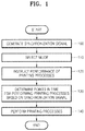
- FIG. 1 is a flowchart illustrating a method of printing using a synchronization signal according to an exemplary embodiment of the present invention.
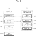
- FIG. 2 is a block diagram illustrating an apparatus for printing using a synchronization signal according to an exemplary embodiment of the present invention. The method of printing using a synchronization signal according to the exemplary embodiment of the present invention will now be described with reference to FIGS. 1 and 2 .
- a synchronization signal generator 203 of a controller 200 generates a synchronization signal (step 100).
- the synchronization signal is used to designate a reference point in time for controlling and performing printing processes.
- a mode selecting unit 220 selects a mode from among a plurality of modes in which the points in time at which the printing processes are to be performed are determined according to the synchronization signal (step 110).
- a mode is selected from among a plurality of modes in step 110.
- the plurality of modes are determined in advance based on experimental results, and stored in a mode storage unit 210.
- a control signal generator 206 instructs a printing process performing unit 230 to perform the printing processes at the required points in time based on the synchronization signal generated in step 100 according to the mode selected in step 110 (step 120).
- a laser scanning unit 232, a scanner 234, a paper supply engine 236, and a fixing unit 238 of the printing process performing unit 230 determine the points in time for performing the printing processes instructed in step 120 based on the synchronization signal generated in step 100 (step 130).
- the laser scanning unit 232, the scanner 234, the paper supply engine 236, and the fixing unit 238 perform the printing processes instructed in step 120 at the points in time determined in step 130 (step 140).
- a controller 200 generates a synchronization signal and controls printing processes performed in an image forming apparatus based on the synchronization signal.
- the controller 200 includes a synchronization signal generator 203 and a control signal generator 206.
- the synchronization signal generator 203 generates the synchronization signal.
- the synchronization signal is used to designate a reference point in time for controlling or for performing printing processes, which are controlled or performed by a laser scanning unit 232, a scanner 234, a paper supply engine 236, and a fixing unit 238 of a printing process performing unit 230 according to control signals output from the control signal generator 206.
- the control signal generator 206 generates the control signals for controlling the printing processes to be performed in the laser scanning unit 232, the scanner 234, the paper supply engine 236, and the fixing unit 238.
- the printing processes are performed according to points in time based on the synchronization signal generated by the synchronization signal generator 203.
- control signal generator 206 is controlled by a control table stored in a mode storage unit 210 according to a mode selected by a mode selecting unit 220.
- the control table stored in the mode storage unit 210 includes information regarding a plurality of modes in which the points in time for performing the printing processes are determined according to the synchronization signal. Examples of the modes stored in the mode storage unit 210, as illustrated in FIG. 3D , include a warm up mode 300, a print mode 310, a ready mode 320, and a termination mode 330.
- the information of the control table stored in the mode storage unit 210 is determined based on experimental results for each mode.
- the mode selecting unit 220 selects a mode in which the image forming apparatus is to operate from the modes stored in the mode storage unit 210.
- the printing process performing unit 230 performs the printing processes in response to the control signals output from the control signal generator 206.
- the printing process performing unit 230 performs the printing processes by determining the points in time for performing the printing processes based on the synchronization signal generated by the synchronization signal generator 203.
- the printing processes are performed by the laser scanning unit 232, the scanner 234, the paper supply engine 236, and the fixing unit 238.
- the laser scanning unit 232, the scanner 234, the paper supply engine 236, and the fixing unit 238 perform the printing processes in response to the control signals output from the control signal generator 206 by determining the points in time for performing the printing processes based on the synchronization signal generated by the synchronization signal generator 206.
- the laser scanning unit 232 receives an image signal and scans a laser beam generated by a light source such as a laser diode onto a photo sensitive medium such as an optical photo conductor drum to form an electrostatic latent image.
- a light source such as a laser diode
- a photo sensitive medium such as an optical photo conductor drum
- the scanner 234 performs scan processes by scanning light onto a document and by using light reflected from the document.
- the paper supply engine 236 supplies or ejects a to-be-fed printing medium such as printing paper along predetermined paper feeding path.
- the fixing unit 238 included in the image forming apparatus fixes a developer on the printing medium by using heat.
- FIG. 3 is a timing diagram explaining printing processes performed in a fixing unit in the method and apparatus of FIGS. 1 and 2 .
- the modes for printing processes performed in the fixing unit 238 include the warm up mode 300, the print mode 310, the ready mode 320, and the termination mode 330. These modes are stored in the mode storage unit 210.
- the mode selecting unit 220 selects the warm up mode 300, the print mode 310, the ready mode 320, or the termination mode 330 according to the progress of the printing process.
- the control signal generator 206 generates the control signals for controlling fixing processes performed by the fixing unit 238 according to the mode selected by the mode selecting unit 220.
- the fixing unit 238 determines the points in time at which the fixing processes are performed based on the synchronization signal and performs the fixing processes in response to the control signals generated by the control signal generator 206.
- an inrush current is reduced based on a phase signal and the level of input power so that soft starting can be controlled.
- the input power increases gradually as a conduction angle increases gradually from an initial value of 0.
- a switch controller 400 gradually increases the number of first through n-th heating elements 410 to 419 that receive power. This increase is made in the warm up mode 300.
- the amount of power required for the fixing processes is controlled to thoroughly distribute the power into sine waves with a nominal carrier.
- the amount of power is controlled to distribute the power into sine waves within 30% of a rated power.
- the fixing unit 238 performs the processes for the modes according to the predetermined control table for the modes based on the synchronization signal generated by the synchronization signal generator 203.
- the printing processes performed in an image forming apparatus are performed by determining the points in time for performing the printing processes based on the synchronization signal.
- the units Accordingly, time is not required for the units to respond to the request of a microprocessor unit (MPU) with information about the current states of the units and the results of processing the control signals. Also, the units perform the printing processes at predetermined times based on the synchronization signal. As a result, the waiting time for printing can be reduced.
- MPU microprocessor unit
- the present invention can also be embodied as computer readable codes on a computer readable recording medium.
- the computer includes any device having information processing capabilities.
- the computer readable recording medium is any data storage device that can store data which can be thereafter read by a computer system. Examples of the computer readable recording medium include read-only memory (ROM), random-access memory (RAM), CD-ROMS, magnetic tapes, hard disks, floppy disks, and optical data storage devices.
- the computer readable recording medium can also be distributed over network-coupled computer systems so that the computer readable codes is stored and executed in a distributed fashion. Also, functional programs, codes, and code segments for accomplishing the present invention can be easily construed as within the scope of the invention by programmers skilled in the art to which the present invention pertains.
Landscapes
- Physics & Mathematics (AREA)
- Engineering & Computer Science (AREA)
- Life Sciences & Earth Sciences (AREA)
- General Physics & Mathematics (AREA)
- Environmental Sciences (AREA)
- General Engineering & Computer Science (AREA)
- Theoretical Computer Science (AREA)
- Biodiversity & Conservation Biology (AREA)
- Animal Husbandry (AREA)
- Zoology (AREA)
- Optics & Photonics (AREA)
- Microelectronics & Electronic Packaging (AREA)
- Accessory Devices And Overall Control Thereof (AREA)
- Control Or Security For Electrophotography (AREA)
- Record Information Processing For Printing (AREA)
- Laser Beam Printer (AREA)
Description
- The present invention relates to an image forming apparatus such as a printer, a facsimile, or a multifunctional peripheral device. More particularly, but not exclusively, the present invention relates to a method and an apparatus for controlling printing processes performed in an image forming apparatus.
- It is desirable to minimize a wait time of a user from the time an image forming apparatus is turned on to the completion of a printing processes. In a conventional image forming apparatus, when a microprocessor unit (MPU) requests information about the current states of units performing the printing processes, the units output the information about the current states of the units in response to the request. When the MPU outputs control signals for controlling the printing processes to be performed in the units by using the output information about the current states of the units, the units perform the printing processes according to the control signals and output the results of processing the control signals to the MPU. Accordingly, the waiting time includes the time required for the units to respond to the MPU with the results of processing the control signals and the information about the current states of the units.
-
US5329343A discloses a temperature control method and apparatus for a fixing apparatus, in which a first roll contacting the back surface of a recording sheet and a second roll contacting the front surface of a recording sheet for fixing a recording sheet carrying a toner image are individually equipped with heating mechanism. -
US2006/239699A1 discloses a method for control of an electrophotographic printer or copier, where information that refers to a single sheet is determined from print data supplied to the printer or copier. Dependent on said information, a transport path of the single sheet through the printer or copier to generate at least one print image on at least one side of the sheet is determined. - Accordingly, there is a desire for an improved system and method for printing using a synchronization signal capable of performing printing processes in an image forming apparatus.
- An aim of exemplary embodiments of the present invention is to address at least the above problems and/or disadvantages and to aim to provide at least some of the advantages described below. Accordingly, exemplary embodiments of the present invention aim to provide a method and apparatus for printing using a synchronization signal capable of performing printing processes in an image forming apparatus by determining points in time for performing the printing processes based on the synchronization signal.
- According to the present invention there is provided an apparatus and method as set forth in the appended claims. Other features of the invention will be apparent from the dependent claims, and the description which follows.
- Other objects, advantages and salient features of the invention will become apparent to those skilled in the art from the following detailed description, which, taken in conjunction with the annexed drawings, discloses exemplary embodiments of the invention.
- For a better understanding of the invention, and to show how embodiments of the same may be carried into effect, reference will now be made, by way of example, to the accompanying diagrammatic drawings in which:
-
FIG. 1 is a flowchart illustrating a method of printing using a synchronization signal according to an exemplary embodiment of the present invention; -
FIG. 2 is a block diagram illustrating an apparatus for printing using a synchronization signal according to an exemplary embodiment of the present invention; -
FIG. 3 is a timing diagram explaining printing processes performed in a fixing unit in the method and apparatus ofFIGS. 1 and2 ; and -
FIGS. 4A and4B illustrate printing processes performed in a warm up mode in a method and apparatus for printing using a synchronization signal according to an exemplary embodiment of the present invention. - The matters defined in the description such as a detailed construction and elements are provided to assist in a comprehensive understanding of the embodiments of the invention. Accordingly, those of ordinary skill in the art will recognize that various changes and modifications of the embodiments described herein can be made without departing from the scope and spirit of the invention. Also, descriptions of well-known functions and constructions are omitted for clarity and conciseness.
-
FIG. 1 is a flowchart illustrating a method of printing using a synchronization signal according to an exemplary embodiment of the present invention.FIG. 2 is a block diagram illustrating an apparatus for printing using a synchronization signal according to an exemplary embodiment of the present invention. The method of printing using a synchronization signal according to the exemplary embodiment of the present invention will now be described with reference toFIGS. 1 and2 . - First, a
synchronization signal generator 203 of acontroller 200 generates a synchronization signal (step 100). According to an exemplary implementation, the synchronization signal is used to designate a reference point in time for controlling and performing printing processes. - A
mode selecting unit 220 selects a mode from among a plurality of modes in which the points in time at which the printing processes are to be performed are determined according to the synchronization signal (step 110). A mode is selected from among a plurality of modes instep 110. The plurality of modes are determined in advance based on experimental results, and stored in amode storage unit 210. - A
control signal generator 206 instructs a printingprocess performing unit 230 to perform the printing processes at the required points in time based on the synchronization signal generated instep 100 according to the mode selected in step 110 (step 120). - A
laser scanning unit 232, ascanner 234, apaper supply engine 236, and afixing unit 238 of the printingprocess performing unit 230 determine the points in time for performing the printing processes instructed instep 120 based on the synchronization signal generated in step 100 (step 130). - The
laser scanning unit 232, thescanner 234, thepaper supply engine 236, and thefixing unit 238 perform the printing processes instructed instep 120 at the points in time determined in step 130 (step 140). - The apparatus for printing using a synchronization signal according to an exemplary embodiment of the present invention will now be described with reference to
FIG. 2 . - A
controller 200 generates a synchronization signal and controls printing processes performed in an image forming apparatus based on the synchronization signal. Thecontroller 200 includes asynchronization signal generator 203 and acontrol signal generator 206. - The
synchronization signal generator 203 generates the synchronization signal. The synchronization signal is used to designate a reference point in time for controlling or for performing printing processes, which are controlled or performed by alaser scanning unit 232, ascanner 234, apaper supply engine 236, and afixing unit 238 of a printingprocess performing unit 230 according to control signals output from thecontrol signal generator 206. Thecontrol signal generator 206 generates the control signals for controlling the printing processes to be performed in thelaser scanning unit 232, thescanner 234, thepaper supply engine 236, and thefixing unit 238. The printing processes are performed according to points in time based on the synchronization signal generated by thesynchronization signal generator 203. In this regard, thecontrol signal generator 206 is controlled by a control table stored in amode storage unit 210 according to a mode selected by amode selecting unit 220. The control table stored in themode storage unit 210 includes information regarding a plurality of modes in which the points in time for performing the printing processes are determined according to the synchronization signal. Examples of the modes stored in themode storage unit 210, as illustrated inFIG. 3D , include awarm up mode 300, aprint mode 310, aready mode 320, and atermination mode 330. The information of the control table stored in themode storage unit 210 is determined based on experimental results for each mode. - The
mode selecting unit 220 selects a mode in which the image forming apparatus is to operate from the modes stored in themode storage unit 210. - The printing
process performing unit 230 performs the printing processes in response to the control signals output from thecontrol signal generator 206. The printingprocess performing unit 230 performs the printing processes by determining the points in time for performing the printing processes based on the synchronization signal generated by thesynchronization signal generator 203. - The printing processes are performed by the
laser scanning unit 232, thescanner 234, thepaper supply engine 236, and thefixing unit 238. According to an exemplary implementation, thelaser scanning unit 232, thescanner 234, thepaper supply engine 236, and thefixing unit 238 perform the printing processes in response to the control signals output from thecontrol signal generator 206 by determining the points in time for performing the printing processes based on the synchronization signal generated by thesynchronization signal generator 206. - The
laser scanning unit 232 receives an image signal and scans a laser beam generated by a light source such as a laser diode onto a photo sensitive medium such as an optical photo conductor drum to form an electrostatic latent image. - The
scanner 234 performs scan processes by scanning light onto a document and by using light reflected from the document. - The
paper supply engine 236 supplies or ejects a to-be-fed printing medium such as printing paper along predetermined paper feeding path. - The
fixing unit 238 included in the image forming apparatus fixes a developer on the printing medium by using heat. -
FIG. 3 is a timing diagram explaining printing processes performed in a fixing unit in the method and apparatus ofFIGS. 1 and2 . - The modes for printing processes performed in the
fixing unit 238 include thewarm up mode 300, theprint mode 310, theready mode 320, and thetermination mode 330. These modes are stored in themode storage unit 210. - The
mode selecting unit 220 selects thewarm up mode 300, theprint mode 310, theready mode 320, or thetermination mode 330 according to the progress of the printing process. Thecontrol signal generator 206 generates the control signals for controlling fixing processes performed by thefixing unit 238 according to the mode selected by themode selecting unit 220. Thefixing unit 238 determines the points in time at which the fixing processes are performed based on the synchronization signal and performs the fixing processes in response to the control signals generated by thecontrol signal generator 206. - In the
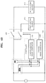
warm up mode 300, an inrush current is reduced based on a phase signal and the level of input power so that soft starting can be controlled. For example, in thewarm up mode 300, as illustrated inFIG. 4A , the input power increases gradually as a conduction angle increases gradually from an initial value of 0. InFIG. 4B , aswitch controller 400 gradually increases the number of first through n-th heating elements 410 to 419 that receive power. This increase is made in the warm upmode 300. - In the
print mode 310, the amount of power required for the fixing processes is controlled to thoroughly distribute the power into sine waves with a nominal carrier. - In the
ready mode 320, the amount of power is controlled to distribute the power into sine waves within 30% of a rated power. - In the
termination mode 330, the power supply is reduced so that soft termination is possible. According to an exemplary implementation, the fixingunit 238 performs the processes for the modes according to the predetermined control table for the modes based on the synchronization signal generated by thesynchronization signal generator 203. - According to the method and apparatus for printing using a synchronization signal according to an embodiment of the present invention, the printing processes performed in an image forming apparatus are performed by determining the points in time for performing the printing processes based on the synchronization signal.
- Accordingly, time is not required for the units to respond to the request of a microprocessor unit (MPU) with information about the current states of the units and the results of processing the control signals. Also, the units perform the printing processes at predetermined times based on the synchronization signal. As a result, the waiting time for printing can be reduced.
- The present invention can also be embodied as computer readable codes on a computer readable recording medium. The computer includes any device having information processing capabilities. The computer readable recording medium is any data storage device that can store data which can be thereafter read by a computer system. Examples of the computer readable recording medium include read-only memory (ROM), random-access memory (RAM), CD-ROMS, magnetic tapes, hard disks, floppy disks, and optical data storage devices. The computer readable recording medium can also be distributed over network-coupled computer systems so that the computer readable codes is stored and executed in a distributed fashion. Also, functional programs, codes, and code segments for accomplishing the present invention can be easily construed as within the scope of the invention by programmers skilled in the art to which the present invention pertains.
- While the present invention has been shown and described with reference to certain exemplary embodiments thereof, it will be understood by those skilled in the art that various changes in form and details may be made therein without departing from the scope of the present invention as defined by the appended claims and their equivalents.
Claims (7)
- A method of printing using a synchronization signal, the method comprising the steps of:generating (100) a synchronization signal to be used to designate a reference point in time for controlling and performing printing processes;selecting (110) one from among a plurality of modes, wherein information regarding the plurality of modes is stored in a mode storage unit and said information includes information regarding at which points in time the printing processes are to be performed, determined according to the synchronization signal;instructing (120) a printing process performing unit to perform the printing processes at the corresponding points in time based on the synchronization signal according to the selected mode;determining (130) the points in time for performing the instructed printing processes based on the synchronization signal; andperforming (140) the instructed printing processes at the determined points in time based on the synchronization signal,wherein the synchronization signal comprises a plurality of waveforms repeated in a predetermined period,wherein the printing processes comprises laser scanning, paper supplying and fixing,wherein the plurality of modes are warm-up mode, print mode, ready mode and termination mode.
- A computer-readable medium having embodied thereon a computer program for executing a method of printing using a synchronization signal, the method comprising the steps of:generating (100) a synchronization signal to be used to designate a reference point in time for controlling and performing printing processes;selecting (110) one from among a plurality of modes, wherein information regarding the plurality of modes is stored in a mode storage unit and said information includes information regarding at which points in time the printing processes are to be performed, determined according to the synchronization signal;instructing (120) a printing process performing unit to perform the printing processes at the corresponding points in time based on the synchronization signal according to the selected mode;determining (130) the points in time for performing the instructed printing processes based on the synchronization signal; andperforming (140) the instructed printing processes at the determined points in time based on the synchronization signal,wherein the synchronization signal comprises a plurality of waveforms repeated in a predetermined period,wherein the printing processes comprises laser scanning, paper supplying and fixing,wherein the plurality of modes are warm-up mode, print mode, ready mode and termination mode.
- An apparatus for printing using a synchronization signal, the apparatus comprising:a mode storage unit (210) for storing information regarding a plurality of modes in which points in time at which printing processes are to be performed are determined according to the synchronization signal;a mode selecting unit (220) for selecting one of the plurality of modes, information on said plurality of modes being stored in the mode storage unit (210), according to the synchronization signal;a printing process performing unit (230) for performing a instructed printing processes at the determined points in time based on the synchronization signal; anda controller (200) configured to generate a synchronization signal to be used to designate a reference point in time for controlling and performing, instruct the printing process performing unit (230) to perform the printing processes at the corresponding points in time based on the synchronization signal according to the selected mode, determine points in time for performing instructed printing processes based on the synchronization signal, and instruct the performance of printing processes,wherein the synchronization signal comprises a plurality of waveforms repeated in a predetermined period,wherein the printing processes comprises laser scanning, paper supplying and fixing,wherein the plurality of modes are warm-up mode, print mode, ready mode and termination mode,wherein the printing process performing unit (230) comprises:a laser scanning unit (232) for receiving an image signal and for scanning a laser beam generated by a light source onto a photo sensitive medium form an electrostatic latent image;a scanner (234) for performing scan processes by at least one of scanning light onto a document and using light reflected from the document;a paper supply engine (236) for at least one of supplying and ejecting a printing medium along a reference paper feeding path; anda fixing unit (238) for fixing a developer on to the printing medium by using heat.
- The apparatus of claim 3, wherein the light source comprises a laser diode.
- The apparatus of claim 3, wherein the photo sensitive medium comprises an optical photo conductor drum.
- The apparatus of claim 3, wherein the printing medium comprises printing paper.
- The apparatus of claim 3, wherein the controller comprises:a synchronization signal generator (203) for generating the synchronization signal; anda printing process controller (206) for generating control signals for controlling the printing processes at points in time based on the synchronization signal,wherein the printing process controller performs the printing processes based on the synchronization signal in response to the control signals.
Applications Claiming Priority (1)
| Application Number | Priority Date | Filing Date | Title |
|---|---|---|---|
| KR1020060023569A KR100782839B1 (en) | 2006-03-14 | 2006-03-14 | Printing method and apparatus using synchronization signal |
Publications (3)
| Publication Number | Publication Date |
|---|---|
| EP1835447A2 EP1835447A2 (en) | 2007-09-19 |
| EP1835447A3 EP1835447A3 (en) | 2013-01-23 |
| EP1835447B1 true EP1835447B1 (en) | 2018-04-18 |
Family
ID=38166687
Family Applications (1)
| Application Number | Title | Priority Date | Filing Date |
|---|---|---|---|
| EP06126054.3A Not-in-force EP1835447B1 (en) | 2006-03-14 | 2006-12-13 | Method and apparatus for printing using synchronization signal |
Country Status (4)
| Country | Link |
|---|---|
| US (2) | US8194264B2 (en) |
| EP (1) | EP1835447B1 (en) |
| KR (1) | KR100782839B1 (en) |
| CN (1) | CN101038456B (en) |
Citations (1)
| Publication number | Priority date | Publication date | Assignee | Title |
|---|---|---|---|---|
| DE10250194A1 (en) * | 2002-10-28 | 2004-05-13 | OCé PRINTING SYSTEMS GMBH | Method and device for controlling an electrographic printer or copier |
Family Cites Families (30)
| Publication number | Priority date | Publication date | Assignee | Title |
|---|---|---|---|---|
| US5329343A (en) * | 1991-05-14 | 1994-07-12 | Fuji Xerox Co., Ltd. | Temperature control method and fixing apparatus |
| KR970011585B1 (en) * | 1992-01-21 | 1997-07-12 | 가부시키가이샤 아드반테스트 | Waveform Shaper of Semiconductor Test Equipment |
| CN1144098A (en) | 1994-01-15 | 1997-03-05 | 河南省密县科学技术研究所 | Oral liquor with functions of reducing blood sugar and invigorating kidney |
| JPH08265581A (en) * | 1995-03-20 | 1996-10-11 | Ricoh Co Ltd | Color image forming apparatus |
| IT1285252B1 (en) * | 1996-02-23 | 1998-06-03 | Technisub Spa | ADJUSTABLE BACK STRAP FOR DIVING AND SWIMMING EQUIPMENT |
| AUPQ104099A0 (en) * | 1999-06-18 | 1999-07-08 | Resmed Limited | Forehead support for facial mask |
| US6317560B1 (en) * | 1997-12-01 | 2001-11-13 | Dai Nippon Printing Co., Ltd. | Photographing system containing synchronizing control data for controlling lighting, photography, printing and guidance based upon the user's choice of photographing mode |
| JPH11327357A (en) * | 1998-05-20 | 1999-11-26 | Fujitsu Ltd | Thermal fixing device temperature control method and apparatus, and image forming apparatus |
| AUPQ102999A0 (en) * | 1999-06-18 | 1999-07-08 | Resmed Limited | A connector for a respiratory mask and a respiratory mask |
| AUPP949999A0 (en) * | 1999-03-29 | 1999-04-22 | Resmed Limited | Forehead support for facial mask II |
| JP2001117414A (en) * | 1999-10-15 | 2001-04-27 | Fujitsu Ltd | Fixing device control method and control device, fixing device and image forming apparatus |
| JP4479054B2 (en) * | 1999-12-14 | 2010-06-09 | コニカミノルタビジネステクノロジーズ株式会社 | Digital copying machine and image data transfer method in digital copying machine |
| US6679261B2 (en) * | 2000-08-24 | 2004-01-20 | Resmed Limited | Forehead support for facial mask |
| JP2002174994A (en) | 2000-12-08 | 2002-06-21 | Canon Inc | Image forming system |
| DE10103154C1 (en) * | 2001-01-24 | 2002-05-23 | Draeger Safety Ag & Co Kgaa | Breathing mask with rapid-release fixing bands has tension device between fixing bands attached at sides of mask for simultaneous release |
| US20030089373A1 (en) * | 2001-06-14 | 2003-05-15 | Gradon Lewis George | Breathing assistance apparatus |
| JP4158365B2 (en) * | 2001-08-27 | 2008-10-01 | ブラザー工業株式会社 | Network terminal equipment |
| JP2003091186A (en) | 2001-09-18 | 2003-03-28 | Fuji Xerox Co Ltd | Fixing device |
| JP2003195680A (en) | 2001-12-26 | 2003-07-09 | Canon Inc | Image forming device |
| JP2003228465A (en) * | 2002-02-01 | 2003-08-15 | Hitachi Printing Solutions Ltd | Printer system |
| US6694532B2 (en) * | 2002-06-25 | 2004-02-24 | High Rainbow Ent. Co., Ltd. | Assembly system for securing an adjusting strap to a frame of goggles |
| US6927368B2 (en) * | 2003-03-27 | 2005-08-09 | Lexmark International, Inc. | Method and apparatus for controlling power to a heater element using dual pulse width modulation control |
| EP1607229A4 (en) * | 2003-03-27 | 2007-08-22 | Seiko Epson Corp | PRINTING DEVICE, OUTPUT DEVICE, AND SCRIPT GENERATING METHOD |
| JP4402384B2 (en) * | 2003-07-17 | 2010-01-20 | 株式会社東芝 | Image forming apparatus, image forming method, and print control apparatus |
| KR20050034887A (en) * | 2003-10-10 | 2005-04-15 | 삼성전자주식회사 | Apparatus and method of generating power source voltage synchronizing signal |
| JP2005149030A (en) * | 2003-11-13 | 2005-06-09 | Seiko Epson Corp | Printing system |
| KR101080400B1 (en) * | 2004-04-03 | 2011-11-04 | 삼성전자주식회사 | Method and apparatus for controling voltage output of an image forming apparatus |
| JP2005338634A (en) * | 2004-05-28 | 2005-12-08 | Ricoh Co Ltd | Image forming apparatus and heater output optimization method for image forming apparatus |
| KR100555678B1 (en) * | 2004-06-03 | 2006-03-22 | 삼성전자주식회사 | Fuser control device for power synchronization signal generation and power supply voltage detection |
| KR100727928B1 (en) * | 2004-11-10 | 2007-06-14 | 삼성전자주식회사 | Fuser, an image forming apparatus having the same, and a fuser control method |
-
2006
- 2006-03-14 KR KR1020060023569A patent/KR100782839B1/en not_active Expired - Fee Related
- 2006-11-20 US US11/601,729 patent/US8194264B2/en not_active Expired - Fee Related
- 2006-12-13 EP EP06126054.3A patent/EP1835447B1/en not_active Not-in-force
-
2007
- 2007-01-15 CN CN2007100020170A patent/CN101038456B/en not_active Expired - Fee Related
-
2012
- 2012-05-03 US US13/463,593 patent/US8670137B2/en not_active Expired - Fee Related
Patent Citations (2)
| Publication number | Priority date | Publication date | Assignee | Title |
|---|---|---|---|---|
| DE10250194A1 (en) * | 2002-10-28 | 2004-05-13 | OCé PRINTING SYSTEMS GMBH | Method and device for controlling an electrographic printer or copier |
| US20060239699A1 (en) * | 2002-10-28 | 2006-10-26 | Oce Printing Systems Gmbh | Method and device for controlling an electrographic printer or copier |
Also Published As
| Publication number | Publication date |
|---|---|
| KR20070093570A (en) | 2007-09-19 |
| CN101038456A (en) | 2007-09-19 |
| US20070216936A1 (en) | 2007-09-20 |
| US8670137B2 (en) | 2014-03-11 |
| US8194264B2 (en) | 2012-06-05 |
| KR100782839B1 (en) | 2007-12-06 |
| CN101038456B (en) | 2012-03-28 |
| EP1835447A2 (en) | 2007-09-19 |
| EP1835447A3 (en) | 2013-01-23 |
| US20120212784A1 (en) | 2012-08-23 |
Similar Documents
| Publication | Publication Date | Title |
|---|---|---|
| US7864348B2 (en) | Printing apparatus printing based on a degree of urgency | |
| JP2014113752A (en) | Image formation apparatus, image formation apparatus control method, and program | |
| US8823973B2 (en) | Image forming apparatus for starting a preparation operation without receiving information about an accessory device | |
| JP5181849B2 (en) | Image forming apparatus, image forming control method, image forming control program, and recording medium | |
| US8305618B2 (en) | Image forming apparatus, activation control method | |
| KR20170133911A (en) | Image forming apparatus and method for controlling fuser | |
| US20130294794A1 (en) | Image forming apparatus, output order setting method, and computer program product | |
| US8194264B2 (en) | Method and apparatus for printing using synchronization signal | |
| US11875073B2 (en) | Printing device with accumulation printing | |
| JP2001287404A (en) | Image forming device | |
| KR101000929B1 (en) | Computer-readable recording medium storing program of printing method using synchronizing signal | |
| JP2000227739A (en) | Image forming device | |
| JP2001156969A (en) | Image forming device | |
| JP2003202777A (en) | Image forming device | |
| JP2009128628A (en) | Image forming device | |
| US20210080884A1 (en) | Start control device and image forming apparatus | |
| JP2000305327A (en) | PRINTING APPARATUS AND CONTROL METHOD OF PRINTING APPARATUS | |
| JP2002067377A (en) | Image forming apparatus and control method thereof | |
| JP2008062612A (en) | Image forming apparatus | |
| CN121879073A (en) | Fixing motor control method, image forming apparatus, and storage medium | |
| JP5663903B2 (en) | Image forming apparatus and image forming method | |
| JP4442852B2 (en) | Image forming apparatus | |
| JPH10319788A (en) | Printing apparatus and print processing method | |
| JP2007264454A (en) | Image forming apparatus | |
| JP2007010789A (en) | Image forming apparatus |
Legal Events
| Date | Code | Title | Description |
|---|---|---|---|
| PUAI | Public reference made under article 153(3) epc to a published international application that has entered the european phase |
Free format text: ORIGINAL CODE: 0009012 |
|
| 17P | Request for examination filed |
Effective date: 20061213 |
|
| AK | Designated contracting states |
Kind code of ref document: A2 Designated state(s): AT BE BG CH CY CZ DE DK EE ES FI FR GB GR HU IE IS IT LI LT LU LV MC NL PL PT RO SE SI SK TR |
|
| AX | Request for extension of the european patent |
Extension state: AL BA HR MK YU |
|
| RAP1 | Party data changed (applicant data changed or rights of an application transferred) |
Owner name: SAMSUNG ELECTRONICS CO., LTD. |
|
| PUAL | Search report despatched |
Free format text: ORIGINAL CODE: 0009013 |
|
| AK | Designated contracting states |
Kind code of ref document: A3 Designated state(s): AT BE BG CH CY CZ DE DK EE ES FI FR GB GR HU IE IS IT LI LT LU LV MC NL PL PT RO SE SI SK TR |
|
| AX | Request for extension of the european patent |
Extension state: AL BA HR MK RS |
|
| RIC1 | Information provided on ipc code assigned before grant |
Ipc: B41J 2/435 20060101ALI20121219BHEP Ipc: G03G 15/00 20060101ALI20121219BHEP Ipc: G06K 15/12 20060101AFI20121219BHEP Ipc: B41J 29/393 20060101ALI20121219BHEP |
|
| AKX | Designation fees paid |
Designated state(s): DE FR GB NL |
|
| 17Q | First examination report despatched |
Effective date: 20160412 |
|
| STAA | Information on the status of an ep patent application or granted ep patent |
Free format text: STATUS: EXAMINATION IS IN PROGRESS |
|
| RAP1 | Party data changed (applicant data changed or rights of an application transferred) |
Owner name: S-PRINTING SOLUTION CO., LTD. |
|
| REG | Reference to a national code |
Ref country code: DE Ref legal event code: R079 Ref document number: 602006055154 Country of ref document: DE Free format text: PREVIOUS MAIN CLASS: G06K0015000000 Ipc: G03G0021140000 |
|
| GRAP | Despatch of communication of intention to grant a patent |
Free format text: ORIGINAL CODE: EPIDOSNIGR1 |
|
| STAA | Information on the status of an ep patent application or granted ep patent |
Free format text: STATUS: GRANT OF PATENT IS INTENDED |
|
| RIC1 | Information provided on ipc code assigned before grant |
Ipc: B41J 29/393 20060101ALI20171204BHEP Ipc: G03G 21/14 20060101AFI20171204BHEP Ipc: B41J 2/435 20060101ALI20171204BHEP Ipc: G06K 15/00 20060101ALI20171204BHEP Ipc: G03G 15/00 20060101ALI20171204BHEP Ipc: G06K 15/12 20060101ALI20171204BHEP |
|
| INTG | Intention to grant announced |
Effective date: 20180103 |
|
| GRAS | Grant fee paid |
Free format text: ORIGINAL CODE: EPIDOSNIGR3 |
|
| GRAA | (expected) grant |
Free format text: ORIGINAL CODE: 0009210 |
|
| STAA | Information on the status of an ep patent application or granted ep patent |
Free format text: STATUS: THE PATENT HAS BEEN GRANTED |
|
| REG | Reference to a national code |
Ref country code: DE Ref legal event code: R081 Ref document number: 602006055154 Country of ref document: DE Owner name: HEWLETT-PACKARD DEVELOPMENT COMPANY, L.P., SPR, US Free format text: FORMER OWNER: SAMSUNG ELECTRONICS CO., LTD., SUWON-SI, GYEONGGI-DO, KR |
|
| AK | Designated contracting states |
Kind code of ref document: B1 Designated state(s): DE FR GB NL |
|
| REG | Reference to a national code |
Ref country code: GB Ref legal event code: FG4D |
|
| REG | Reference to a national code |
Ref country code: DE Ref legal event code: R096 Ref document number: 602006055154 Country of ref document: DE |
|
| RAP2 | Party data changed (patent owner data changed or rights of a patent transferred) |
Owner name: HP PRINTING KOREA CO., LTD. |
|
| REG | Reference to a national code |
Ref country code: NL Ref legal event code: MP Effective date: 20180418 |
|
| PG25 | Lapsed in a contracting state [announced via postgrant information from national office to epo] |
Ref country code: NL Free format text: LAPSE BECAUSE OF FAILURE TO SUBMIT A TRANSLATION OF THE DESCRIPTION OR TO PAY THE FEE WITHIN THE PRESCRIBED TIME-LIMIT Effective date: 20180418 |
|
| REG | Reference to a national code |
Ref country code: DE Ref legal event code: R097 Ref document number: 602006055154 Country of ref document: DE |
|
| PLBE | No opposition filed within time limit |
Free format text: ORIGINAL CODE: 0009261 |
|
| STAA | Information on the status of an ep patent application or granted ep patent |
Free format text: STATUS: NO OPPOSITION FILED WITHIN TIME LIMIT |
|
| 26N | No opposition filed |
Effective date: 20190121 |
|
| REG | Reference to a national code |
Ref country code: GB Ref legal event code: 732E Free format text: REGISTERED BETWEEN 20200220 AND 20200226 |
|
| REG | Reference to a national code |
Ref country code: DE Ref legal event code: R082 Ref document number: 602006055154 Country of ref document: DE Representative=s name: SCHOPPE, ZIMMERMANN, STOECKELER, ZINKLER, SCHE, DE Ref country code: DE Ref legal event code: R081 Ref document number: 602006055154 Country of ref document: DE Owner name: HEWLETT-PACKARD DEVELOPMENT COMPANY, L.P., SPR, US Free format text: FORMER OWNER: S-PRINTING SOLUTION CO., LTD., SUWON-SI, GYEONGGI-DO, KR |
|
| PGFP | Annual fee paid to national office [announced via postgrant information from national office to epo] |
Ref country code: FR Payment date: 20210608 Year of fee payment: 16 |
|
| PGFP | Annual fee paid to national office [announced via postgrant information from national office to epo] |
Ref country code: GB Payment date: 20211118 Year of fee payment: 16 Ref country code: DE Payment date: 20210528 Year of fee payment: 16 |
|
| REG | Reference to a national code |
Ref country code: DE Ref legal event code: R119 Ref document number: 602006055154 Country of ref document: DE |
|
| GBPC | Gb: european patent ceased through non-payment of renewal fee |
Effective date: 20221213 |
|
| PG25 | Lapsed in a contracting state [announced via postgrant information from national office to epo] |
Ref country code: GB Free format text: LAPSE BECAUSE OF NON-PAYMENT OF DUE FEES Effective date: 20221213 Ref country code: DE Free format text: LAPSE BECAUSE OF NON-PAYMENT OF DUE FEES Effective date: 20230701 |
|
| PG25 | Lapsed in a contracting state [announced via postgrant information from national office to epo] |
Ref country code: FR Free format text: LAPSE BECAUSE OF NON-PAYMENT OF DUE FEES Effective date: 20221231 |