EP1835446A2 - Feature point detecting device, feature point detecting method, and feature point detecting program - Google Patents
Feature point detecting device, feature point detecting method, and feature point detecting program Download PDFInfo
- Publication number
- EP1835446A2 EP1835446A2 EP07250627A EP07250627A EP1835446A2 EP 1835446 A2 EP1835446 A2 EP 1835446A2 EP 07250627 A EP07250627 A EP 07250627A EP 07250627 A EP07250627 A EP 07250627A EP 1835446 A2 EP1835446 A2 EP 1835446A2
- Authority
- EP
- European Patent Office
- Prior art keywords
- dimensional
- node
- model
- face
- feature
- Prior art date
- Legal status (The legal status is an assumption and is not a legal conclusion. Google has not performed a legal analysis and makes no representation as to the accuracy of the status listed.)
- Granted
Links
Images


Classifications
-
- G—PHYSICS
- G06—COMPUTING; CALCULATING OR COUNTING
- G06V—IMAGE OR VIDEO RECOGNITION OR UNDERSTANDING
- G06V10/00—Arrangements for image or video recognition or understanding
- G06V10/70—Arrangements for image or video recognition or understanding using pattern recognition or machine learning
- G06V10/74—Image or video pattern matching; Proximity measures in feature spaces
- G06V10/75—Organisation of the matching processes, e.g. simultaneous or sequential comparisons of image or video features; Coarse-fine approaches, e.g. multi-scale approaches; using context analysis; Selection of dictionaries
- G06V10/755—Deformable models or variational models, e.g. snakes or active contours
- G06V10/7553—Deformable models or variational models, e.g. snakes or active contours based on shape, e.g. active shape models [ASM]
-
- G—PHYSICS
- G06—COMPUTING; CALCULATING OR COUNTING
- G06V—IMAGE OR VIDEO RECOGNITION OR UNDERSTANDING
- G06V20/00—Scenes; Scene-specific elements
- G06V20/60—Type of objects
- G06V20/64—Three-dimensional objects
- G06V20/647—Three-dimensional objects by matching two-dimensional images to three-dimensional objects
-
- G—PHYSICS
- G06—COMPUTING; CALCULATING OR COUNTING
- G06V—IMAGE OR VIDEO RECOGNITION OR UNDERSTANDING
- G06V20/00—Scenes; Scene-specific elements
- G06V20/60—Type of objects
- G06V20/64—Three-dimensional objects
- G06V20/653—Three-dimensional objects by matching three-dimensional models, e.g. conformal mapping of Riemann surfaces
Definitions
- the present invention relates to a technique that is effective when applied to a device, a method or a program, etc., for detecting feature points of an object from an image.
- a technique for detecting the feature points of the object from the image includes a technique of detecting the feature points of a face.
- the related art for when the object is a face will be described below.
- the closing and opening information of the eye, face orientation, viewing direction, facial expression, etc. of a person can be estimated by obtaining the positions of the feature points of the face from the image in which the person is imaged.
- the state of the relevant person can be understood in more detail from the estimation result.
- the performance of a man-machine interface may be enhanced and a new service may be provided by understanding the state of the person in detail. Therefore, it is important to accurately learn the positions of the feature points of the face in developing the man-machine interface.
- a driver monitoring system is an example of the man-machine interface.
- the opening and closing of the eye, the face orientation, the viewing direction, etc. of the driver are observed. Then, appropriate advice is given based on the degree of fatigue, etc of the driver determined from the observation result.
- a method of obtaining the positions of the feature points from the image is a method that employs template matching, and the application thereof.
- the general information (hereinafter referred to as “feature value”) of each feature point are stored in advance.
- the feature value obtained from one region of the image and the stored feature value are compared, and determination is made on whether or not the feature point obtained is the feature point to be acquired.
- a specific example of the feature value used in this case is a luminance value vector of the image.
- means for comparing the feature values generally includes using normal correlation or Euclidean distance.
- a technique for reducing the number of search points in advance by means of a separation degree filter, and thereafter detecting the feature point candidates through pattern matching has been proposed (refer to, Japanese Laid-Open Patent Publication No. 9-251534 ) as an example of feature point detecting technique.
- geometrical restraining conditions are applied after the feature point candidates are detected, and the combination of candidate points determined most likely to look like a human face is output.
- Other methods of obtaining the face orientation include a method of preparing a template of the entire face or of the feature values of the face in correspondence to a plurality of directions of the face, and performing a match with the template. In such methods as well, however, whether or not the estimation of the face orientation can be accurately performed depends on the accuracy of the positions of the feature points of the face. Therefore, the estimation of the face orientation cannot be accurately performed unless the positions of the feature points of the face are accurately acquired.
- ASM Active Shape Model
- the face shape model is arranged at an appropriate initial position of the image to be processed.
- a plurality of feature values around the node is acquired for each node of the face shape model.
- the acquired plurality of feature values and the feature values associated with the relevant node in advance are then compared.
- Each node is moved to a position where the feature value closest to the feature value corresponding to each node is acquired (i.e., the position at which the possibility of being the feature point corresponding to each node is the highest) out of the positions at which the plurality of feature values are acquired.
- the position of each node of the face shape model is displaced from the initial position..
- the deformed node set is shaped by projecting it onto the face shape model.
- the processes after acquiring the feature value around each node are repeatedly performed over a predetermined number of times or until a constant condition (restraining condition) is met.
- the final position of each node is then determined as the position of each feature point.
- ASM projection onto the face shape model is performed after the position of each node is moved. According to this process, the accurate position of the feature point can be detected with the positional relationship of each node maintaining a face-like shape. In other words, even if by chance a portion having a feature value similar to a feature point exists at a position not acceptable in forming the shape of the face of a normal person, such a point is prevented from being mistakenly detected as the feature point.
- AAM Active Appearance Model
- ASM Active Appearance Model
- the position of a feature point is obtained in the following manner. First, the positions of the feature points are acquired for a large number of training face images, and a face shape model is created, similar to ASM Next, a mean value for all relevant feature points among the large number training face images is determined for each feature point in the face shape model. Subsequently an average shape model is constructed from the set of feature points that are closest to the previously calculated mean values.
- Feature points are taken from the learning face images to create a plurality of patches; each patch is projected onto the mean shape model, and a shape free image is created (this process is referred to as the "shape correcting process").
- the node position is fitted onto the mean shape model thus resulting in the shape free image in which only luminance value information remains.
- a patch is a plane formed from a plurality of nodes or feature points at its vertices.
- a face luminance value model shape free face luminance value model is created by performing main component analysis on a set of shape free images.
- the face shape model is minutely displace by a constant amount in each to obtain a shape free luminance value vector.
- Linear regression is performed on the relevant set of vectors..
- the above-described processes are executed in advance as learning processes in AAM.
- the face shape model is arranged at an appropriate initial position of the image to be processed.
- a patch is then created based on the node position of the arranged face shape model, and the luminance distribution in each patch is sampled.
- the shape free face luminance value model is created by projecting the sampled luminance distribution onto the image.
- the amount of movement and deformity of the face shape model is estimated from the shape free face luminance value model by a regression expression obtained in advance.
- the face shape model is moved and deformed according to the estimation result.
- the above processes are repeatedly executed over a predetermined number of times or until a constant condition (restraining condition) is met.
- the final position of each node is then determined to be position of each feature point.
- the position of each feature point is detected without performing a search of the peripheral region of each node.
- time is not required for a search of the peripheral region of each node, as opposed to ASM, and the calculation time can be reduced.
- the accurate position of the feature point can be detected with the positional relationship of each node maintaining a face-like shape, similar to ASM, since the search is performed by deforming the shape model.
- the AAM has the following drawbacks.
- a homogeneous and high density sampling must be performed when acquiring the luminance distribution of each patch in order to maintain the accuracy of position detection of each feature point by AAM.
- the calculation amount in sampling and in projecting the luminance distribution onto the mean shape model becomes large, and a large amount of calculation time is required.
- the amount of movement and the amount of deformity of the face shape model are estimated based on linear regression by minute displacement around the correct point. Thus, accurate estimation cannot be performed for large displacements, and a correct result cannot be obtained.
- the first aspect of the present invention relates to a feature point detecting device for estimating a three dimensional position of a plurality of feature points in an image of a predetermined object from an input image.
- the object herein may be any object as long as a shape model can be set.
- the object may be a face of a person, whole (entire body) person, or organs in an X-ray or CT (Computed Tomography) image.
- CT Computer Tomography
- the feature point detecting device includes a model creating means, a projecting means, a feature value acquiring means, a storing means, an error estimated amount acquiring means, and an estimating means.
- the model creating means creates a three dimensional model in which the three dimensional position of a plurality of nodes each corresponding to the plurality of feature points is defined. Each node is corresponded to each feature point to be detected.
- the created three dimensional model is desirably a position at where the projection point of projecting each node of the three dimensional model on the input image is assumed to be close to the corresponding feature point of each node.
- the initial position and the orientation of the three dimensional model created based on such reference are desirably defined in advance.
- the center of the screen is assumed as the initial position and assumed as facing the front based on experiences that most objects are imaged facing the front at the center of the screen.
- the projecting means projects each node defined by the three dimensional model onto the input image, and calculates the position of the relevant projection in an image plane.
- the feature value acquiring means acquires the feature value as a node feature value of each node of the three dimensional model from a plurality of sampling points around the projection point of each node projected by the projecting means.
- the feature value include luminance value of the pixel, the Sobel filter feature value, the Harr Wavelet feature value, the Gabor Wavelet feature value, and the composite value thereof.
- the arrangement of sampling points may be non-homogeneous and of low density.
- the storing means stores the learning result executed in advance.
- the learning result is acquired by performing the learning process on a plurality of learning images. Specifically, information on the correlation of the following two values is acquired as learning result in advance.
- One of the values is the difference between a correct model which is a three dimensional model in which the plurality of nodes are respectively arranged at a correct three dimensional position of the corresponding feature points and an error model which is a three dimensional model in which at least one of the plurality of nodes is arranged at a position displaced from the correct position of the corresponding feature point.
- the other value is a node feature value described above acquired based on the projection point of when the error model is projected onto the learning image.
- the information on the correlation of such two values is acquired by analyzing methods such as canonical correlation analysis, linear regression, multiple linear regression, multiple non-linear regression , etc..
- the error estimated amount acquiring means acquires the error estimated amount indicating the displacement between the position of each node of the current three dimensional model and the position of the corresponding feature point based on the information on the correlation stored in the storing means and the node feature value of each node acquired by the feature value acquiring means.
- the estimating means estimates the three dimensional position of each feature point in the input image based on the error estimated amount obtained by the error estimated amount acquiring means and the position of each node of the current three dimensional model. That is, the feature point detecting device detects each feature point at each three dimensional position estimated by the estimating means.
- the shape correcting process is not necessary according to the first aspect of the present invention.
- the shape correcting process is not performed according to the first aspect of the present invention.
- a great amount of processes performed for the shape correcting process are omitted, thereby increasing the speed of the process.
- the searching process does not need to be performed around each node, and high density sampling serving as a plane does not need to be performed in a patch configured by each node according to the first aspect of the present invention.
- a great amount of calculations required by sampling in the prior art can be reduced.
- the man-machine interface described above can be operated at high speed as the speed of the detection process of the feature point becomes higher. For example, in the driver monitoring system that requires response due to its property, such request which is not realized in the prior art can now be solved.
- the first aspect of the present invention may also include an end determining means for determining the end of the repetitive process.
- the end determining means may be configured to count the number of times the repetitive processes have been executed, and end the process when reaching a predetermined number of times. If the end determining means is arranged, the model creating means moves the position of each current node based on the error estimated amount and creates a new three dimensional model when the error estimated amount is obtained.
- the model crating means and the error estimated amount acquiring means repeatedly execute the processes, and the estimating means estimates the three dimensional position of each feature point in the input image based on the error estimated amount at the point in time determination is made by the end determining means to end the process and the three dimensional model at the relevant point in time.
- the error estimated amount is again obtained based on the new three dimensional model in which the three dimensional position of each node is moved based on the error estimated amount, and the processes are repeated.
- the three dimensional position of each feature point is then estimated based on the error estimated amount at the point in time determination is made to end the repetitive process and the three dimensional model at the relevant point in time.
- the end determining means in the first aspect of the present invention may be configured to determine to end the repetitive process when the error estimated amount obtained by the error estimated amount acquiring means becomes less than or equal to a threshold value. According to such configuration, the position of each feature point is more accurately detected.
- the model creating module may change the process of creating the new three dimensional model based on the error estimated amount depending on the number of repetitions when performing the repetitive process. For example, the model creating module moves and/or rotates each node while maintaining the relative position relationship of each current node based on the error estimated amount in the initial stage of the repetitive process to change the orientation of the three dimensional model and create a new three dimensional model.
- the first aspect of the present invention suitably targets the face of the person as the predetermined object.
- the first aspect of the present invention may further include a face detecting module for detecting the position of at least the face of the person or the element of the face of the person (organs or portion in the face, for example, eye, nose, mouse, forehead etc.) from the input image.
- the model creating module determines the three dimensional position of each node in the three dimensional model based on the position of the detected face of the person or the element of the face of the person. According to such configuration, the initial position of each node becomes an appropriate position, that is, a position close to the corresponding feature point
- the feature point detection is performed using the three dimensional node model specialized for the size of the face detected by the face detecting module and the information on the correlation corresponding to the relevant three dimensional node model.
- the second aspect of the present invention is a feature point detecting device for estimating a three dimensional arrangement of the feature point of the face in the input image using a three dimensional face shape model representing a three dimensional arrangement of a plurality of feature points in the face of the person.
- the feature point detecting device includes a model creating means, a projecting means, a feature value acquiring means, a storing means, an error estimated amount acquiring means, a changing means and an estimating means.
- the model creating means creates a three dimensional face shape model representing the three dimensional arrangement of a plurality of features points in the face of the person.
- the projecting means projects each node of the three dimensional face shape model created by the model creating means onto an input image plane; and determines the position of the projection point in the image plane.
- the feature value acquiring means discretely acquires a plurality of feature values around the position of the projection point of each node of the three dimensional face shape model projected by the projecting means, and acquires the plurality of feature values acquired based on one projection point as one node feature value.
- the storing means stores a transformation vector matrix, that is, an error estimation matrix acquired in advance through canonical correlation analysis.
- the inputs of the canonical correlation process are a set of vectors indicating the difference, in the position of each node, between a correct three dimensional face shape model and an error three dimensional face shape model and a set of node feature values obtained by projecting the error three dimensional face shape model onto a learning image.
- a correct three dimensional face shape model is a face shape model in which each node is arranged at a correct position.
- an error three dimensional face shape model is a face shape model in which at least one of the nodes is arranged displaced from the correct position.
- the error estimated amount acquiring means acquires the error estimated amount indicating the displacement between the current position of each node of the three dimensional face shape model and the position of the feature point of the face based on the error estimation matrix stored in the storing means and the set of node feature values acquired by the feature value acquiring means.
- the changing means changes the position of each node of the current three dimensional face shape model based on the error estimated amount obtained by the error estimated amount acquiring means.
- the estimating means estimates the position of each node after the position is changed by the changing means as the position of the feature point.
- First and second aspects may be realized by executing a program by an information processing device. That is, the present invention may specify the processes executed by each means in the first and second aspects described above as a program to be executed by the information processing device or as a recording medium recorded with the relevant program. Furthermore, the present invention may specify the processes executed by each means described above with a method executed by the information processing device.
- the information processing device herein includes a personal computer, digital camera, digital video camera, security camera" portable telephone equipped with the digital camera, digital video recorder, server that performs image processing (may be server connected to a network), digital photo printer, a miniature laboratory equipment etc.
- the shape correcting process is conventionally performed as in AAM to generally perform error estimation (estimation of moving direction and moving amount to the correct point of each node in the shape model). Therefore, the omission of the shape correcting process has not been considered when performing error estimation.
- the required shape correcting process is assumed as one of the causes that increase the calculation amount in the conventional AAM. Consequently, the inventors of the present invention thus considered a device for detecting the feature point without performing the shape correcting process.
- a high density sampling is generally performed around each node to maintain high accuracy of error estimation.
- homogeneous and high density samplings specifically, normally ten thousand or more samplings
- low density sampling has not been considered when performing error estimation.
- Such homogeneous and the high density sampling is one of the causes that increase the calculation amount in the conventional AAM. Consequently, the inventors of the present invention thus considered a device for detecting the feature point without performing the homogenous and high density sampling.
- the position of the feature point is conventionally captured on the image plane (two dimensional). Therefore, the position of the feature point is determined on the image plane, and then the orientation of the object is estimated based on the relevant position of the feature point in order to obtain the orientation of the object (e.g., face of person). Representing the shape model three dimensionally thus has not been considered. However, the orientation of the object can be directly obtained from the position of the detected feature points if the three dimensional model is used for the shape model. Thus, the inventors of the present invention thus considered a device for detecting the feature point using the three dimensional shape model.
- the inventors of the present invention came up with the following ideas.
- the sampling is performed in the patch configured by each node in the error estimation of the conventional AAM.
- the result of the sampling is treated as a patch, it is difficult to maintain the accuracy of the process without performing the shape correcting process.
- the accuracy of the process can thus be maintained without particularly performing the shape correcting process.
- the inventors of the present invention therefore, provide the following feature point detecting device based on the considered results.
- the present invention aims to provide a device, a program , etc. for detecting the position of the feature point from the image at high speed.
- face image is an image including an image of at least one part of or the entire face of the person. Therefore, the face image may include an image of the entire person or may include an image of only the face or only the upper half of the body of the person. The face image may also include an image of a great number of people. Moreover, the face image may include various patterns including landscape, patterns etc. other than the person in the background (background: include object given attention as a subject).
- the inventors of the present invention have used a three dimensional shape model for a shape model in ASM and further combined feature value sampling by variable retina structure and an error estimation matrix learning by canonical correlation analysis to realize a high speed feature point detection.
- the feature point detection of high robustness is also realized by such combination.
- the face orientation may even be estimated at the same as the detection of the feature point with such combination.
- the learning process necessary in operating the feature point detecting device 1 will be described first.
- the learning process is a process that must be performed in advance to detect the position of the feature points from the face image by the feature point detecting device 1.
- the processes necessary in describing the flow of the learning process that is, acquisition of a three dimensional face shape model, projection of the three dimensional face shape model onto an image plane, retina sampling, and acquisition of error estimation matrix will be described. Thereafter, an example of a specific flow of the learning process will be described.
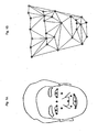
- FIG. 1A shows a view of an example of the feature points extracted from the face image. In FIG. 1A, the center position of a shaded circle becomes the feature point.
- both ends inner corner of the eye, tail of the eye
- the center portion of both eyes left and right cheek bone portions (orbital floor portion), top of the nose, left and right corners of the mouth, center of the mouth, intermediate points of the left and right end points of the nose and the left and right corners of the mouth etc. are the feature points.
- FIG. 1A has been illustrated as a plane view to describe the position of the feature points, but the feature points are actually extracted in a three dimensional coordinate as shown in FIG. 1 B.
- the coordinate of each feature point pi is assumed as pi(x i , y i , z i ).
- i is a value between 1 and n (n is the number of feature points).
- a feature point arrangement vector X for each face image is defined as in equation 1.
- the feature point arrangement vector for a certain face image j is written as X j .
- the number of dimensions of X is 3n.
- all the acquired feature point arrangement vectors X are normalized based on an appropriate reference.
- the reference of normalization is appropriately determined by the designer.
- a specific example of normalization will be described below. If, for example, the barycentric coordinate of points p1 to p n is p G with regards to the feature point arrangement vector X j for a certain face image j, each point is moved to the coordinate system having the center of gravity p G as the origin, and the size thereof is normalized using L m defined by equation 2. Specifically, the size is normalized by dividing the coordinate value after movement by L m . L m is an average value of a linear distance from the center of gravity to each point
- normalization is carried out by performing rotational transformation on the feature point coordinate so that the line connecting the centers of both eyes, for example, lie a certain direction.
- the above processes are represented by a combination of rotation and enlargement/reducfion, and the feature point arrangement vector x after normalization is expressed as in equation 3 (similarity transformation).
- R x s ⁇ R x ⁇ R y ⁇ R z ⁇ X + t
- R x 1 0 0 0 cos ⁇ - sin ⁇ 0 sin ⁇ cos ⁇ ]
- R y [ cos ⁇ 0 sin ⁇ 0 1 0 - sin ⁇ 0 cos ⁇ ]
- the main component analysis is thereafter performed on the set of normalized feature point arrangement vectors.
- the main component analysis can be performed as below.
- an average vector (average vector is indicated with a horizontal line above x) is acquired according to the equation shown in equation 4.
- N indicates the number of face images, that is, the number of feature point arrangement vectors.
- a differential vector x' is acquired by subtracting the average vector from all normalized feature point arrangement vectors, as shown in equation 5.
- the differential vector for image j is indicated as x' j .
- P indicates the eigenvector matrix
- b indicates the shape parameter vector.
- the respective values are as shown in equation 7.
- e i indicates the eigenvector.
- the arbitrary normalized feature point arrangement vector x can be approximated and expressed as in equation 8 by using the values up to the high order k th dimension having a large eigenvalue.
- e i will be hereinafter referred to as the i th main component in the order of large eigenvalue.
- a model parameter k can be expressed as in equation 9 in combination with the shape parameter.
- the relevant parameter is referred to as a three dimensional correct model parameter in the relevant face image.
- the determination on whether or not an accurate match is found is made based on a threshold value or a reference set by the designer.
- the three dimensional shape model is processed on the two dimensional image by being projected onto the two dimensional plane.
- Various methods such as parallel projection method and perspective projection method are used as a method of projecting the three dimensional shape onto the two dimensional plane.
- An example of a single point perspective projection of the perspective projection methods will be described herein. Similar effects are obtained with any other methods.
- the three dimensional shape model is thus projected onto the two dimensional plane according to the above processes.
- FIG. 2 shows a view of an example of the retina structure.
- the coordinate of the feature point of interest is the origin and each point positioned at other coordinates is the sampling point in the retina structure.
- the information around the feature point can be efficiently sampled at low dimension by performing sampling with retina structure.
- sampling with retina structure is performed at the projection point (each point p) of each node of the face shape model (hereinafter referred to as two dimensional face shape model) projected onto the two dimensional plane from the three dimensional face shape model.
- Sampling with retina structure means performing sampling at sampling points defined according to the retina structure.
- FIG. 3 shows a view of a distribution example of the sampling points when the retina structure is applied to a certain node of the two dimensional face shape model.
- the shaded circle indicates the node of the face shape model
- the black circle indicates the sampling point in the retina structure.
- the retina structure is expressed as in equation 13 with the coordinate of the i th sampling point as q i (x i , y i ).
- the retina feature value f p obtained by performing sampling with retina structure with respect to a certain point p(x p , y p ), etc. is expressed as in equation 14.
- f(p) indicates the feature value at point p (sampling point p).
- the luminance value of the pixel, the Sobel filter feature value, the Harr Wavelet feature value, the Gabor Wavelet feature value, and the composite value thereof are acquired at each sampling point in the retina structure as the feature value at the relevant sampling point. If the feature value is multi-dimensional, the retina feature value is expressed as in equation 15.
- D indicates the number of dimensions of the feature value
- f d (p) indicates the feature value of the d th dimension at point p.
- q i (d) indicates the i th sampling coordinate of the retina structure with respect to the d th dimension.
- the size of the retina structure can be changed according to the scale of the face shape model.
- the size of the retina structure can be changed inversely proportional to the parallel movement parameter S z .
- the retina structure r for this case is expressed as in equation 16.
- ⁇ is an appropriate fixed value.
- the retina structure may be rotated or shape changed according to other parameters in the face shape model.
- the retina structure may also be set so that the shape (structure) differs among each node of the face shape model.
- the retina structure may be a structure with only the center point. That is, the retina structure may be the structure having only the feature point (node) as the sampling point.
- the sampling feature value f is defined as a vector in which the retina feature values obtained by performing sampling for every projection point of each node projected onto the projection plane are lined in one column.
- the sampling feature value f is expressed as in equation 17.
- n indicates the number of nodes in the face shape model.
- Normalization is performed at each node at the time of sampling. For example, normalization is carried out by performing a scale transformation so that the feature value is within the range of 0 to 1. Normalization may also be carried by performing transformation to obtain a constant average or variance. Normalization is sometimes not performed depending on the feature value.
- the acquisition of the error estimation matrix executed in the present learning process will now be described.
- the error estimation matrix is acquired using canonical correlation analysis.
- the canonical correlation analysis is one method of obtaining the correlation between two variates having different dimensions.
- the correlation learning result that is, the direction to move each node when each node of the face shape model is arranged at the wrong position (a position different form the feature point to be detected), can be obtained using canonical correlation analysis.
- the three dimensional face shape model is created from the three dimensional position information of the feature point of the learning face image.
- the three dimensional face shape model is created from the two dimensional correct coordinate point of the learning face image.
- the correct model parameter is created from the three dimensional face shape model.
- a displaced arrangement model in which at least one of the nodes is displaced from the three dimensional position of the feature point is obtained by displacing the correct model parameter within a constant range by a random number etc.
- FIG. 4 shows a view of an example of the projection point of each node when the displaced arrangement model is projected onto the learning face image. In FIG. 4, the shaded circle indicates the position of the projection point.
- FIG. 4A shows a view of the position of the projection point of each node obtained by projecting the correct model parameter in a certain face image onto the learning face image.
- FIG. 4B shows a view of the position of the projection point of each node obtained by projecting the displaced arrangement model created by displacing the correct model (three dimensional face shape model represented by correct model parameter) shown in FIG. 4A onto the learning face image.
- the learning result regarding the correlation is obtained with the sampling feature value acquired based on the displaced arrangement model, and the difference between the displaced arrangement model and the correct model as a set. A specific process will be described below.
- x indicates the sampling feature value with respect to the displaced arrangement model.
- y indicates the difference between the correct model parameter (k opt ) and the displaced arrangement model parameter (parameter indicating displaced arrangement model: k dif ).
- Two sets of variate vectors are normalized in advance to average 0 and variance 1 with respect to each dimension.
- the parameters (average, variance of each dimension) used for normalization are necessary in the detection process of the feature point to be hereinafter described.
- the respective parameters x ave , x var , y ave , y var are referred to as normalization parameters.
- a and b are obtained as eigenvectors with respect to the maximum eigenvalue of when solving a general eigenvalue problem shown in equation 21 in consideration of simultaneous distribution of x and y and with the variance-covariance matrix ⁇ thereof defined as in equation 20.
- the eigenvalue problem of lower dimension is solved first. If the maximum eigenvalue obtained by solving the first equation is ⁇ 1 and the corresponding eigenvector is a 1 , vector b 1 is obtained by the equation shown in equation 22.
- Equation 22 b 1 1 ⁇ 1 ⁇ Y ⁇ Y - 1 ⁇ Y ⁇ X ⁇ a 1
- ⁇ 1 obtained in such manner is referred to as the first canonical correlation coefficient.
- u 1 and v 1 expressed by equation 23 are referred to as first canonical variate.
- the vector used in the detection process of the feature point (to be hereinafter described) is assumed to be a vector up to the M th canonical variate whose eigenvalue has a value (threshold value) greater than or equal to a constant.
- the threshold value may be appropriately determined by the designer.
- the transformation vector matrix up to the M th canonical variate is assumed as A' and B' and is called the error estimation matrix. A' and B' are expressed as in equation 24.
- B' is generally not a square matrix. However, since an inverse matrix is necessary in the detection process of the feature point, zero vector is pseudo-added to B' thereby obtaining a square matrix B".
- the square matrix B" is expressed as in equation 25.
- Equation 25 B " b 1 , ... , b M , 0 ... , 0
- the error estimation matrix may be obtained through analyzing methods such as linear regression, multiple linear regression, multiple non-linear regression or the like. However, the influence of the variate corresponding to a small eigenvalue may be ignored by using the canonical correlation analysis. Therefore, the effect of factors that do not influence the error estimation can be eliminated, thereby allowing a more stable error estimation. Thus, the error estimation matrix may be acquired using other analyzing methods mentioned above in place of the canonical correlation analysis if the relevant effects are not necessary. The error estimation matrix may also be acquired by methods such as SVM, RVM , etc..
- FIG. 5 shows a flow chart illustrating an example of the flow of the learning process.
- the example of the flow of the learning process will now be described using FIG. 5.
- the processes described below are executed by an information processing device installed with a learning process program.
- the information processing device is configured to read, from the storage device connected thereto, the learning face image and the three dimensional coordinate position (correct coordinate of feature point) of each feature point extracted in advance in each face image.
- the information processing device may be configured to read data not only from the storage device but also through the network or by accessing a recording medium and like.
- a variable i is defined and 1 is substituted (S01).
- the i th face image (Img_i) out of the learning face images which three dimensional position of the feature points are acquired in advance is then read (S02).
- the first face image (Img_1) is read in this case because 1 is substituted to i.
- the set of correct coordinates of the feature points of the face image Img_i is then read, and the correct model parameter k opt is acquired to create the three dimensional face shape model (correct model) (S03).
- the displaced arrangement model parameter k dif is then created based on the correct model parameter k opt to create the displaced arrangement model (S04).
- the displaced arrangement model is preferably created by producing random numbers and displacing each node in the correct model within a predetermined range.
- the displaced arrangement model is then projected onto the learning image (S05).
- Sampling using retina structure is then carried out based on the two dimensional shape model projected with the displaced arrangement model, and the sampling feature value f_i is acquired (S06).
- the error (displacement) dp_i of the shape model is acquired based on the correct model parameter k opt and the displaced arrangement model parameter k dif (S07).
- Determination is then made whether the processes are completed for all learning face images (S08). For example, determination can be made by comparing the value of i and n, which indicates the number of learning face images.
- the value of i is incremented (S09), and the processes after S02 are executed based on the new value of i. If determined that processes are completed for all face images (308-Yes), the canonical correlation analysis is executed for the set of the sampling feature value f_i and the error dp_i of the shape model obtained for each face image (S10). The unnecessary correlation matrix corresponding to the eigenvalue smaller than the threshold value defined in advance is deleted (S11) and the error estimation matrix is ultimately acquired (S12).
- the feature point detecting device 1 will now be described.
- the feature point detecting device 1 detects feature points from the input face image based on the error estimation matrix obtained by the above learning processes, the normalization parameter etc.
- the device configuration of the feature point detecting device 1 will now be described.
- the feature point detecting device 1 is configured including a CPU (Central Processing Unit), a main storage unit (RAM), an auxiliary storage unit etc. connected by way of a bus in terms of hardware. In this case, the feature point detecting device 1 is realized by executing the program by the CPU.
- the auxiliary storage unit mentioned herein is configured using a non-volatile storage unit.
- the non-volatile storage unit is a so-called ROM (Read-Only Memory): EPROM (Erasable Programmable Read-Only Memory), EEPROM (Electrically Erasable Programmable Read-Only Memory), mask ROM etc.), FeRAM (Ferroelectric RAM), hard disk, etc..
- FIG. 6 shows a view of an example of function blocks of the feature point detecting device 1.
- the feature point detecting device 1 functions as a device including an image inputting section 2, a face detecting section 3, a feature value acquiring section 4, a learning result storing section 5, an error estimating section 6, etc. by loading various programs (OS, application etc.) stored in the auxiliary storage unit in to the main storage unit, and executing the programs by the CPU.
- the feature point detecting device 1 may be entirely or partially configured as a dedicated chip. Each function section arranged in the feature point detecting device 1 will now be described.
- the image inputting section 2 functions as an interface for inputting the data of the face image into the feature point detecting device 1.
- the data of the face image is input to the feature point detecting device 1 by the image inputting section 2.
- the image inputting section 2 may be configured using any existing techniques for inputting the data of the face image to the feature point detecting device 1.
- the data of the face image may be input to the feature point detecting device 1 via the network (e.g., local area network, intemet).
- the image inputting section 2 is configured using the network interface.
- the data of the face image may also be input to the feature point detecting device 1 from digital camera, scanner, personal computer, recording device (e.g., hard disc drive) , etc..
- the image inputting section 2 is configured according to the standard (e.g., standards of wired connection such as USB (Universal Serial Bus), SCSI (Small Computer System Interface) etc., and wireless connection such as Bluetooth (registered trademark) etc.) for data communicatably connecting the digital camera, the personal computer, the recording device etc. and the feature point detecting device 1.
- the data of the face image recorded on the recording medium may be input to the feature point detecting device 1.
- the image inputting section 2 is configured using a device for reading the data from the recording medium (e.g., flash memory reader, floppy (registered trademark) disc drive, CD drive, and DVD drive).
- the feature point detecting device 1 may be interiorly arranged in an imaging device such as digital camera or in various devices (e.g., PDA (Personal Digital Assistant) and portable telephones) equipped with the imaging device such as digital camera, and the imaged image is input to the feature point detecting device 1 as data of the face image.
- the image inputting section 2 may be configured using a CCD (Charge-Coupled Devices), CMOS (Complementary Metal-Oxide Semiconductor) sensor , etc., or may be configured as an interface for inputting the data of the face image imaged by CCD, CMOS sensor or the like to the feature point detecting device 1.
- CCD Charge-Coupled Devices
- CMOS Complementary Metal-Oxide Semiconductor
- the feature point detecting device 1 may be interiorly arranged in an image output device such as a printer, display or the like, and the image input to the image output device as output data may be input to the feature point detecting device 1 as data of the face image.
- the image inputting section 2 is configured using a device for converting the data of the face image input to the image output device to the data capable of being handled in the feature point detecting device 1.
- the image inputting section 2 may also be configured to respond to a plurality of the above cases.
- the face detecting section 3 detects the face of a person from the face image input via the image inputting section 2.
- the face detecting section 3 may be configured to detect the face through template matching using a reference template corresponding to the contour of the entire face.
- the face detecting section 3 may also be configured to detect the face through template matching based on the constituting features (eye, nose, ear etc.) of the face.
- the face detecting section 3 may further be configured to detect the vertex of the head etc. by Chromakey process to detect the face based on the vertex.
- the face detecting section 3 may also be configured to detect a region close to the color of the skin to detect the relevant region as the face.
- the face detecting section 3 may further be configured to perform learning by a teaching signal using neural network to detect the face-like region as the face.
- the face detection process of the face detecting section 3 may be realized by applying any other existing techniques.
- the face detecting section 3 specifies the position of the detected face and sends the relevant position to the feature value acquiring section 4.
- the face detecting section 3 may be configured to acquire the tilt of the face or the size of the face, and send the value thereof to the feature value acquiring section 4.
- the feature value acquiring section 4 acquires the sampling feature value from the image of the face of the person detected by the face detecting section 3. A specific process of the feature value acquiring section 4 will now be described.
- the feature value acquiring section 4 first determines the three dimensional position of each node in the three dimensional face shape model and acquires the parameter (initial parameter) k init of the shape model when acquiring the sampling feature value for the first time with respect to the face detected by the face detecting section 3.
- the three dimensional shape model may be, for example, a shape in which the center of the detected face and the center of the three dimensional face shape model coincide.
- the three dimensional shape model is a shape in which the predetermined nodes of the face shape model are arranged at predetermined positions from a certain vertex (e.g., upper left corner) of the face square.
- the three dimensional face shape model created by the feature value acquiring section 4 may be defined by the designer in various manners as long as the nodes are appropriately arranged with respect to the detected face. Each node is corresponded to each feature point to be detected.
- the created three dimensional model is desirably a position at where the projection point of projecting each node of the three dimensional model on the input image is assumed to be close to the corresponding feature point of each node. Therefore, the initial position and the orientation of the three dimensional model created based on such reference are desirably defined in advance. For example, the center of the screen is assumed as the initial position and assumed as facing the front based on experiences that most objects are imaged facing the front at the center of the screen.
- the initial parameter k init refers to the model parameter represented by the initial value out of the model parameters k expressed by equation 9.
- An appropriate value may be set for the initial parameter k init .
- Various directions, change in expression etc. of the face can be responded by setting an average value obtained from a general face image as the initial parameter k init . Therefore, the average value of the correct model parameter of the face image used in the learning process may be used for the parameters s x , sy, s z , s ⁇ , s ⁇ , and s ⁇ of the similarity transformation.
- the shape parameter b may be zero. If the information on the direction of the face is obtained by the face detecting section 3, the initial parameter is set using such information. The designer may set other values obtained through experience as the initial parameter.
- the feature value acquiring section 4 then projects the face shape model represented by the set initial parameter onto the input face image.
- the feature value acquiring section 4 then performs sampling based on the retina structure using the projected shape model, and acquires the sampling feature value f.
- the feature value acquiring section 4 sends the obtained sampling feature value f to the error estimating section 6.
- the feature value acquiring section 4 acquires the sampling feature value with respect to the face detected by the face detecting section 3 for the second or subsequent times, the sampling feature value f is obtained for the face shape model represented by a new model parameter k (i.e., estimated value k i+1 of correct model parameter) obtained by the error estimating section 6. In this case as well, the feature value acquiring section 4 sends the obtained sampling feature value f to the error estimating section 6.
- the learning result storing section 5 configured using a non-volatile storage unit, stores the learning result obtained through the learning processes described above. Specifically, the learning result storing section 5 stores the error estimation matrix, the normalization parameter etc. The learning result storing section 5 may further store the initial parameter k init or some of the values (e.g., average value of similarity transformation parameter in correct model parameter of face image used in learning process etc.) constituting the initial parameter k init , as necessary.
- the error estimating section 6 estimates the error amount and acquires a new model parameter k based on the sampling feature value f acquired by the feature value acquiring section 4, and the error estimation matrix, the normalization parameter etc. stored in the learning result storing section 5. A specific processing example of the error estimating section 6 will now be described.
- the error estimating section 6 first normalizes the sampling feature value f acquired by the feature value acquiring section 4 using the normalization parameters (X ave , x var ), and acquires the vector x for performing the canonical correlation analysis.
- the error estimating section 6 acquires a variate u by calculating first to M th canonical variate based on the equation shown in equation 26.
- the error estimating section 6 then acquires the normalized error estimated amount y using the equation shown in equation 27.
- equation 27 if B' is not a square matrix, B' T-1 is a pseudo-inverse matrix of B'.
- the error estimating section 6 then performs a restoration process using the normalization parameter (y ave , y var ) with respect to the normalized error estimated amount y to acquire the error estimated amount k err .
- k err is the error estimated amount from the current model parameter k i to the correct model parameter k opt . Therefore, the estimated value k i+1 of the correct model parameter is acquired by adding the error estimated amount k err to the current model parameter k i .
- k err contains error. Therefore, in order to perform a more stable detection, the estimated value k i+1 of the correct model parameter is acquired by the equation shown in equation 28.
- ⁇ is an appropriate fixed value, and may be appropriately determined by the designer. Furthermore, ⁇ may be changed according to the change in i.
- the error estimating section 6 approaches the estimated amount k i of the correct model parameter to the correct parameter by repeating sampling and error estimation. When performing such repetitive processes, the error estimating section 6 makes a determination on whether or not to end the process every time the estimated amount k 1 is obtained. For example, the error estimating section 6 may determine to end the process if the value of i exceeds a threshold value. The error estimating section 6 may also determine to end the process every time the value of ⁇ k expressed by equation 29 becomes less than or equal to a threshold value. The error estimating section 6 may also determine whether or not to end the process based on whether or not the value of the acquired k i+1 is within a normal range.
- the error estimating section 6 may determine to end the process by outputting an error if the value of the acquired k i+1 clearly does not indicate the correct position in the image of the face of the person.
- the error estimating section 6 may also determine to end the process by outputting an error when some of the nodes represented by the acquired k i+1 are outside the image to be processed.
- the error estimating section 6 sends the acquired estimated value k i+1 of the correct model parameter to the feature value acquiring section 4 when determining to continue the process.
- the error estimating section 6 outputs the estimated value k i (or k i+1 ) of the correct model parameter obtained at the relevant point in time as a final estimation parameter k est .
- FIG. 7 shows a flow chart illustrating an operational example of the feature point detecting device 1.
- the feature point detecting device 1 reads the image to be processed through the image inputting section 2 (S20).
- the face detecting section 3 detects the face of the target from the image to be processed.
- the feature value acquiring section 4 arranges the three dimensional face shape model, which is based on the initial parameter k init , at the initial position obtained according to the result of the face detection process by the face detecting section 3 (S21).
- the feature value acquiring section 4 defines the variable i and substitutes 1.
- the feature value acquiring section 4 also defines k i and substitutes the initial parameter k init (S22).
- the feature value acquiring section 4 projects the three dimensional face shape model represented by k i onto the image to be processed (S23).
- the feature value acquiring section 4 acquires the sampling feature value f according to the projected two dimensional shape model (S24).
- the error estimating section 6 uses the acquired sampling feature value f, the error estimating method stored in the learning result storing section 5, etc to acquire the estimated error k err between the three dimensional shape model k i and the correct model parameter.. (S25).
- the error estimating section 6 calculates the estimated value k i+1 of the correct model parameter based on the estimated error according to equation 28 (S26).
- the error estimating section 6 then calculates ⁇ k as the difference between k i+1 and k i (S27), and calculates E as the square of ⁇ k (S28).
- the error estimating section 6 determines whether or not to end the process.
- the error estimating section 6 In determining whether or not to end the process, the error estimating section 6 first determines whether or not k i+1 is within a normal range (S29). If the value of k i+1 is not within the normal range (S29-No), the error estimating section 6 outputs an error to the output device, etc. (not shown) (S30), and the feature point detecting device 1 ends the process. If the value of k ⁇ +1 is within the normal range (S29-Yes), on the other hand, determination is made on whether or not the value of E acquired in the process of S28 is above the threshold value ( ⁇ ) (S31). If E is not above the threshold value (S31-Yes), the error estimating section 6 assumes that the process is converging and outputs k est (S32), and the feature point detecting device 1 ends the process.
- the error estimating section 6 sends the value of k i+1 to the feature value acquiring section 4.
- the feature value acquiring section 4 then creates a new three dimensional face shape model based on the value of k i+1 (S33).
- the error estimating section 6 then increments the value of i (S34).
- the feature value acquiring section 4 projects the new three dimensional face shape model onto the image to be processed, and performs acquisition of the sampling feature value f etc. That is, the processes after S23 are repeated based on the new three dimensional face shape model.
- the shape correcting process is optional in the feature point detecting device 1.
- the detection process of the feature point is performed by non-homogeneous and low density sampling based on retina structure in the feature point detecting device 1. Specifically, detection process usually becomes possible at about a few hundred samplings. According to such feature point detecting device 1, the amount of calculation required in detecting the feature point is thus greatly reduced compared to the prior art. Furthermore, the amount of data to be saved as learning result is reduced since the sampling points are reduced.
- the influence of excess factors, which become the cause of prediction error can be eliminated in advance since the error estimation matrix is obtained through canonical correlation analysis. Furthermore, the error estimating process can be performed at high speed since error estimation is performed only through linear calculation.
- Stable feature point detection is performed even if some of the feature points are hidden in the face image to be processed or the size greatly differs from the face of the learning image since the feature point detecting device 1 searches for the feature point using the face shape model. Stable result of more satisfactory accuracy is obtained since the three dimensional face shape model is used as the face shape model.
- the face orientation of the (direction and angle the face is facing) can be directly obtained from the detection process or the detection result since the three dimensional face shape model is used.
- the orientation of the face can be obtained from the parameters s ⁇ , S ⁇ , and s ⁇ in the face shape model parameter output by the feature point detecting device 1.
- the relative position of each current node may be changed based on the error estimated amount to create the new three dimensional model. According to such configuration, it is possible to perform feature point detection that is robust with respect to change in direction of the object that appears in the input image.
- the face detecting module may be configured to further detect the direction of the face of the person.
- the model creating module includes a three dimensional node model in which the three dimensional position of each node is defined, and may be configured to deform the three dimensional node model based on the direction of the face detected by the face detecting module and use the same. For example, the model creating module rotates each node of the three dimensional node model to match the face facing left when the direction of the face is detected as facing left by the face detecting module.
- the model creating module may be configured to perform the above-mentioned rotation process for a given direction when a face facing another direction is detected. According to such configuration, the position of each feature point is more accurately detected in comparison to using a non-deforming three dimensional node model prepared in advance.
- the face detecting module may be configured to further detect the size of the face of the person.
- the model creating module includes a three dimensional node model in which the three dimensional position of each node in the three dimensional model is defined, and may be configured to deform the three dimensional node model based on the size of the face detected by the face detecting module and use the same.
- the model creating module may be configured to enlarge or reduce the three dimensional node model based on the size of the face detected by the face detecting module and use the same. According to such configuration, the position of each feature point is more accurately detected compared to using a non-deforming three dimensional node model prepared in advance.
- the face detecting module may be configured to further detect the direction of the face of the person.
- the model creating module may be configured to include a plurality of three dimensional models in which the three dimensional position of each node in a given three dimensional model is defined according to the direction of the face.
- the model creating module may be configured to include three dimensional node models corresponding to each of the face facing right, the face facing front, the face facing left, the face facing up, and the face facing down.
- the storing module may also be configured to store information on the correlation corresponding to each three dimensional node model obtained in advance using the learning image in which the face facing the corresponding direction is imaged.
- the model creating module may be configured to select the three dimensional node model to use based on the direction of the face detected by the face detecting module.
- the error estimated amount acquiring module may be configured to read the information on the correlation corresponding to the three dimensional node model selected by the model creating module from the storing module and use the same.
- the feature point detection is performed using the three dimensional node model specialized for the direction of the face detected by the face detecting module and the information on the correlation corresponding to the relevant three dimensional node model.
- the face detecting module may be configured to further detect the size of the face of the person.
- the model creating module may be configured to include a plurality of three dimensional models in which the three dimensional position of each node in the three dimensional model is defined according to the size of the face.
- the storing module may be configured to store information on the correlation corresponding to each three dimensional node model obtained in advance using the learning image in which the face of the corresponding size is imaged.
- the model creating module may be configured to select the three dimensional node model to use based on the size of the face detected by the face detecting module.
- the error estimated amount acquiring module may be configured to read the information on the correlation corresponding to the three dimensional node model selected by the model creating module from the storing module and use the same.
- the sampling points at which the feature value acquiring module acquires the node feature value may be discretely arranged around the projection point of the node.
- the sampling points at which the feature value acquiring module acquires the node feature value in may be configured to be denser towards the projection point of the node and be less dense away from the projection point of the node.
- the sampling points at which the feature value acquiring module acquires the node feature value may be configured to include a retina structure.
- the feature value acquiring module in may be configured to store a plurality of different retina structures, and determine the plurality of sampling points according to the retina structure corresponding to the projection point of each node.
- the learning result storing section 5 may store in advance the initial parameter k init indicating the state of the plurality of faces.
- the learning result storing section 5 may store the value of the initial parameter k init corresponding to the face facing the side, the face facing up, etc.
- the feature value acquiring section 4 may change the face shape model to use depending on the value of the acquired k i+1 . For example, the range of the face shape models covered by each initial parameter is first defined in advance.
- the feature value acquiring section 4 may be configured to discard the value of k i+1 , read an initial parameter different from the initial parameter k init from the learning result storing section 5 and re-execute the processes after S21 based on the newly read value of the initial parameter.
- the feature value acquiring section 4 may change the face shape model to use in the detection process with respect to the face image input next according to the value of k i+1 obtained at a certain point in time if the detection process of the feature point is repeatedly executed. If the face contained in the image to be processed is facing the side, results of higher precision are obtained by performing the process using the initial parameter indicating the face shape model of the face facing the side rather than continuing the process using the model represented by k i+1 . Therefore, in such case, it is effective to configure the feature value acquiring section 4 according to the above modification.
- the feature value acquiring section 4 may be configured to switch the retina structure, the error estimation matrix etc. instead of the initial parameter k init .
- consideration is made in performing the initial correct model parameter estimation with the face parameter fixed and having only the parameter of movement/rotation changed, and performing the process of estimating the shape parameter after the movement/rotation parameter is more or less determined.
- the model parameter is approached to the correct parameter using the parameters s x , s y , s z , s ⁇ , s ⁇ , and s ⁇ related to the movement and rotation taken from the error estimated amount k err .
- the model parameter is approached to the correct parameter using the shape parameters b 1 , b 2 , ..., b k from the error estimated amount k err .
- shape parameters b 1 , b 2 , ..., b k from the error estimated amount k err .
- the error estimating section 6 does not need to determine whether or not to end the process, and may simply output the value of k i+1 obtained at the relevant point in time as k est .
- the feature point detecting device 1 may be configured without the face detecting section 3.
- the feature value acquiring section 4 is configured to perform the process with the center of the screen as the initial position.
- the face detecting section 3 may be arranged exterior to the feature point detecting device 1, and the position information of the detected face may be input with the face image to the feature point detecting device 1.
- the face detecting section 3 may be configured to detect the eye, the mouth or other feature points of the person instead of the face itself.
- the feature value acquiring section 4 is configured to determine the initial value based on the position of such feature point.
- the feature value acquiring section 4 may arrange the sampling points based on structures other than the retina structure. For example, the feature value acquiring section 4 may acquire the feature value from a plurality of points discretely arranged around the projection point of the node.
- the feature point detecting device 1 has been described to estimate the position of the feature point of the face of the person, with the object being the face of the person, but the object may be other than the face of the person.
- the feature point detecting device 1 may estimate the position of the feature point with the object being objects having individual difference in size such as whole (whole body of) person, organs etc. in X-ray image or CT image, or objects that deform without changing the basic shape thereof.
- the feature point detecting device 1 may also estimate the position of the feature point for rigid bodies that do not deform such as industrial products including automobile etc. since the shape model may be set with respect to the rigid body.
- a higher speed and more accurate feature point detection device and / or process can be realized if implemented according to any of the above-mentioned embodiments of the invention.
Abstract
Description
- The present invention relates to a technique that is effective when applied to a device, a method or a program, etc., for detecting feature points of an object from an image.
- A technique for detecting the feature points of the object from the image includes a technique of detecting the feature points of a face. The related art for when the object is a face will be described below.
- The closing and opening information of the eye, face orientation, viewing direction, facial expression, etc. of a person can be estimated by obtaining the positions of the feature points of the face from the image in which the person is imaged. In addition, the state of the relevant person can be understood in more detail from the estimation result. Further, the performance of a man-machine interface may be enhanced and a new service may be provided by understanding the state of the person in detail. Therefore, it is important to accurately learn the positions of the feature points of the face in developing the man-machine interface.
- A driver monitoring system is an example of the man-machine interface. In this system, the opening and closing of the eye, the face orientation, the viewing direction, etc. of the driver are observed. Then, appropriate advice is given based on the degree of fatigue, etc of the driver determined from the observation result.
- Furthermore, application to moving picture video camera, still image camera etc. are other examples of the man-machine interface. In these devices, various processes such as changing the photographing conditions become possible by learning the face orientation of the person to be photographed. Moreover, an individual can be identified with high precision by analyzing in detail the image of the feature points such as the eye, the mouth, etc.
- Generally, a method of obtaining the positions of the feature points from the image (hereinafter referred to as "feature point detecting method") is a method that employs template matching, and the application thereof. In such method, the general information (hereinafter referred to as "feature value") of each feature point are stored in advance. Then, the feature value obtained from one region of the image and the stored feature value are compared, and determination is made on whether or not the feature point obtained is the feature point to be acquired. A specific example of the feature value used in this case is a luminance value vector of the image. In addition, means for comparing the feature values generally includes using normal correlation or Euclidean distance.
- A technique for reducing the number of search points in advance by means of a separation degree filter, and thereafter detecting the feature point candidates through pattern matching has been proposed (refer to,
Japanese Laid-Open Patent Publication No. 9-251534 - In this technique, however, only the feature points of the image of the person, who is facing more or less to the front, under satisfactory photographing conditions can be detected. Therefore, the feature points are difficult to accurately detect from an image in which some of the feature points are hidden by an object or from an image in which the photographing conditions (for example, the lighting conditions) greatly differ from the time of acquiring the feature points that were stored in advance.
- Techniques for estimating the face orientation by obtaining the positions of the feature points of the face have also been proposed (refer to,
Japanese Laid-Open Patent Publication No. 2000-97676 Japanese Laid-Open Patent Publication No. 2003-141551 - A technique referred to as ASM (Active Shape Model) (refer to, for example, A. Lanitis, C.J. Taylor, T.F. Cootes, "Automatic Interpretation and Coding of Face Images Using Flexible Models. IEEE PAMI Vol. 19, No. 7 pp. 743-756, July, 1997) is known as a technique for solving the above problems. In ASM, the positions of the feature points are acquired in advance for a great number of training face images, and the face shape model is created and stored. The face shape model is configured by nodes corresponding to each feature point. The details of the face shape model will be described in later.
- The process of detecting the position of the feature point from the image by ASM will now be described. First, the face shape model is arranged at an appropriate initial position of the image to be processed. Next, a plurality of feature values around the node is acquired for each node of the face shape model. The acquired plurality of feature values and the feature values associated with the relevant node in advance are then compared. Each node is moved to a position where the feature value closest to the feature value corresponding to each node is acquired (i.e., the position at which the possibility of being the feature point corresponding to each node is the highest) out of the positions at which the plurality of feature values are acquired. At this point, the position of each node of the face shape model is displaced from the initial position.. Consequently, the deformed node set is shaped by projecting it onto the face shape model. The processes after acquiring the feature value around each node are repeatedly performed over a predetermined number of times or until a constant condition (restraining condition) is met. The final position of each node is then determined as the position of each feature point.
- In ASM, projection onto the face shape model is performed after the position of each node is moved. According to this process, the accurate position of the feature point can be detected with the positional relationship of each node maintaining a face-like shape. In other words, even if by chance a portion having a feature value similar to a feature point exists at a position not acceptable in forming the shape of the face of a normal person, such a point is prevented from being mistakenly detected as the feature point.
- However, a search (acquisition of feature value and comparison thereof) of the peripheral region must be performed at each node in conventional ASM. Thus, a large amount of calculation time is required. Moreover, conventional ASM has a drawback in that the robustness is low. In other words, if the direction of the face in the image to be processed differs greatly from the direction of the face assumed in the face shape model arranged at the initial position, the detection of the feature points tends to fail.
- AAM (Active Appearance Model) is a technique proposed for solving the problems of ASM (refer to, T.F. Cootes, G.J. Edwards and C.J. Taylor. "Active Appearance Models", IEEE PAMI, Vol. 23, No. 6, pp. 681-685, 2001). In AAM, the position of a feature point is obtained in the following manner. First, the positions of the feature points are acquired for a large number of training face images, and a face shape model is created, similar to ASM Next, a mean value for all relevant feature points among the large number training face images is determined for each feature point in the face shape model. Subsequently an average shape model is constructed from the set of feature points that are closest to the previously calculated mean values. Feature points are taken from the learning face images to create a plurality of patches; each patch is projected onto the mean shape model, and a shape free image is created (this process is referred to as the "shape correcting process"). In order to remove changes to the node position influenced by facial expression, facial direction, and various idiosyncrasies of an individuals face, etc, found in an image, the node position is fitted onto the mean shape model thus resulting in the shape free image in which only luminance value information remains. A patch is a plane formed from a plurality of nodes or feature points at its vertices. A face luminance value model (shape free face luminance value model) is created by performing main component analysis on a set of shape free images. Subsequently, starting from the correct position, the face shape model is minutely displace by a constant amount in each to obtain a shape free luminance value vector. Linear regression is performed on the relevant set of vectors.. Thus, it is possible to estimate the amount and direction needed to move and/or deform a point in the minutely displaced face luminance value vector to obtain a correct point in the face shape model. The above-described processes are executed in advance as learning processes in AAM.
- The process of detecting the position of the feature point from the image using AAM will now be described. First, the face shape model is arranged at an appropriate initial position of the image to be processed. Next, a patch is then created based on the node position of the arranged face shape model, and the luminance distribution in each patch is sampled. Then, the shape free face luminance value model is created by projecting the sampled luminance distribution onto the image.
- The amount of movement and deformity of the face shape model is estimated from the shape free face luminance value model by a regression expression obtained in advance. The face shape model is moved and deformed according to the estimation result. The above processes are repeatedly executed over a predetermined number of times or until a constant condition (restraining condition) is met. The final position of each node is then determined to be position of each feature point.
- According to AAM, the position of each feature point is detected without performing a search of the peripheral region of each node. Thus, time is not required for a search of the peripheral region of each node, as opposed to ASM, and the calculation time can be reduced. Moreover, the accurate position of the feature point can be detected with the positional relationship of each node maintaining a face-like shape, similar to ASM, since the search is performed by deforming the shape model.
- However, the AAM has the following drawbacks.
- A homogeneous and high density sampling must be performed when acquiring the luminance distribution of each patch in order to maintain the accuracy of position detection of each feature point by AAM. Thus, the calculation amount in sampling and in projecting the luminance distribution onto the mean shape model becomes large, and a large amount of calculation time is required. Moreover, in AAM, the amount of movement and the amount of deformity of the face shape model are estimated based on linear regression by minute displacement around the correct point. Thus, accurate estimation cannot be performed for large displacements, and a correct result cannot be obtained.
- Therefore, detection of the feature point cannot be performed at high speed since a large amount of calculation is required during the search process, the shape correcting process of the luminance distribution by homogeneous and high density sampling etc. in the processes using the conventional ASM and AAM. However, response is often required as the detection result of the feature point is used as input data in the man-machine interface , etc.. Thus, the request to perform the detection of the feature point at high speed is also increasing.
- The first aspect of the present invention relates to a feature point detecting device for estimating a three dimensional position of a plurality of feature points in an image of a predetermined object from an input image. The object herein may be any object as long as a shape model can be set. For example, the object may be a face of a person, whole (entire body) person, or organs in an X-ray or CT (Computed Tomography) image. In other words, the present technique is applicable to objects having individual difference in size or ' objects that deform without changing the basic shape thereof.
- The feature point detecting device according to the first aspect of the present invention includes a model creating means, a projecting means, a feature value acquiring means, a storing means, an error estimated amount acquiring means, and an estimating means. The model creating means creates a three dimensional model in which the three dimensional position of a plurality of nodes each corresponding to the plurality of feature points is defined. Each node is corresponded to each feature point to be detected. In addition, the created three dimensional model is desirably a position at where the projection point of projecting each node of the three dimensional model on the input image is assumed to be close to the corresponding feature point of each node. Therefore, the initial position and the orientation of the three dimensional model created based on such reference are desirably defined in advance. For example, the center of the screen is assumed as the initial position and assumed as facing the front based on experiences that most objects are imaged facing the front at the center of the screen.
- The projecting means projects each node defined by the three dimensional model onto the input image, and calculates the position of the relevant projection in an image plane.
- The feature value acquiring means acquires the feature value as a node feature value of each node of the three dimensional model from a plurality of sampling points around the projection point of each node projected by the projecting means. Specific examples of the feature value include luminance value of the pixel, the Sobel filter feature value, the Harr Wavelet feature value, the Gabor Wavelet feature value, and the composite value thereof. Furthermore, the arrangement of sampling points may be non-homogeneous and of low density.
- The storing means stores the learning result executed in advance. The learning result is acquired by performing the learning process on a plurality of learning images. Specifically, information on the correlation of the following two values is acquired as learning result in advance. One of the values is the difference between a correct model which is a three dimensional model in which the plurality of nodes are respectively arranged at a correct three dimensional position of the corresponding feature points and an error model which is a three dimensional model in which at least one of the plurality of nodes is arranged at a position displaced from the correct position of the corresponding feature point. The other value is a node feature value described above acquired based on the projection point of when the error model is projected onto the learning image. The information on the correlation of such two values is acquired by analyzing methods such as canonical correlation analysis, linear regression, multiple linear regression, multiple non-linear regression , etc..
- The error estimated amount acquiring means acquires the error estimated amount indicating the displacement between the position of each node of the current three dimensional model and the position of the corresponding feature point based on the information on the correlation stored in the storing means and the node feature value of each node acquired by the feature value acquiring means.
- The estimating means estimates the three dimensional position of each feature point in the input image based on the error estimated amount obtained by the error estimated amount acquiring means and the position of each node of the current three dimensional model. That is, the feature point detecting device detects each feature point at each three dimensional position estimated by the estimating means.
- Firstly, the shape correcting process is not necessary according to the first aspect of the present invention. In other words, the shape correcting process is not performed according to the first aspect of the present invention, Thus, a great amount of processes performed for the shape correcting process are omitted, thereby increasing the speed of the process.
- Secondly, the searching process does not need to be performed around each node, and high density sampling serving as a plane does not need to be performed in a patch configured by each node according to the first aspect of the present invention. Thus, a great amount of calculations required by sampling in the prior art can be reduced.
- The man-machine interface described above can be operated at high speed as the speed of the detection process of the feature point becomes higher. For example, in the driver monitoring system that requires response due to its property, such request which is not realized in the prior art can now be solved.
- The first aspect of the present invention may also include an end determining means for determining the end of the repetitive process. The end determining means may be configured to count the number of times the repetitive processes have been executed, and end the process when reaching a predetermined number of times. If the end determining means is arranged, the model creating means moves the position of each current node based on the error estimated amount and creates a new three dimensional model when the error estimated amount is obtained. The model crating means and the error estimated amount acquiring means repeatedly execute the processes, and the estimating means estimates the three dimensional position of each feature point in the input image based on the error estimated amount at the point in time determination is made by the end determining means to end the process and the three dimensional model at the relevant point in time.
- According to the first aspect of the present invention configured as above, the error estimated amount is again obtained based on the new three dimensional model in which the three dimensional position of each node is moved based on the error estimated amount, and the processes are repeated. The three dimensional position of each feature point is then estimated based on the error estimated amount at the point in time determination is made to end the repetitive process and the three dimensional model at the relevant point in time.
- The end determining means in the first aspect of the present invention may be configured to determine to end the repetitive process when the error estimated amount obtained by the error estimated amount acquiring means becomes less than or equal to a threshold value. According to such configuration, the position of each feature point is more accurately detected.
- The model creating module according to the first aspect of the present invention may change the process of creating the new three dimensional model based on the error estimated amount depending on the number of repetitions when performing the repetitive process. For example, the model creating module moves and/or rotates each node while maintaining the relative position relationship of each current node based on the error estimated amount in the initial stage of the repetitive process to change the orientation of the three dimensional model and create a new three dimensional model.
- The first aspect of the present invention suitably targets the face of the person as the predetermined object. The first aspect of the present invention may further include a face detecting module for detecting the position of at least the face of the person or the element of the face of the person (organs or portion in the face, for example, eye, nose, mouse, forehead etc.) from the input image. In this case, the model creating module determines the three dimensional position of each node in the three dimensional model based on the position of the detected face of the person or the element of the face of the person. According to such configuration, the initial position of each node becomes an appropriate position, that is, a position close to the corresponding feature point
- In the first aspect of the present invention configured as above, the feature point detection is performed using the three dimensional node model specialized for the size of the face detected by the face detecting module and the information on the correlation corresponding to the relevant three dimensional node model.
- The second aspect of the present invention is a feature point detecting device for estimating a three dimensional arrangement of the feature point of the face in the input image using a three dimensional face shape model representing a three dimensional arrangement of a plurality of feature points in the face of the person. The feature point detecting device according to the second aspect of the present invention includes a model creating means, a projecting means, a feature value acquiring means, a storing means, an error estimated amount acquiring means, a changing means and an estimating means.
- The model creating means creates a three dimensional face shape model representing the three dimensional arrangement of a plurality of features points in the face of the person.
- The projecting means projects each node of the three dimensional face shape model created by the model creating means onto an input image plane; and determines the position of the projection point in the image plane.
- The feature value acquiring means discretely acquires a plurality of feature values around the position of the projection point of each node of the three dimensional face shape model projected by the projecting means, and acquires the plurality of feature values acquired based on one projection point as one node feature value.
- The storing means stores a transformation vector matrix, that is, an error estimation matrix acquired in advance through canonical correlation analysis. The inputs of the canonical correlation process are a set of vectors indicating the difference, in the position of each node, between a correct three dimensional face shape model and an error three dimensional face shape model and a set of node feature values obtained by projecting the error three dimensional face shape model onto a learning image. A correct three dimensional face shape model is a face shape model in which each node is arranged at a correct position. Similarly, an error three dimensional face shape model is a face shape model in which at least one of the nodes is arranged displaced from the correct position.
- The error estimated amount acquiring means acquires the error estimated amount indicating the displacement between the current position of each node of the three dimensional face shape model and the position of the feature point of the face based on the error estimation matrix stored in the storing means and the set of node feature values acquired by the feature value acquiring means.
- The changing means changes the position of each node of the current three dimensional face shape model based on the error estimated amount obtained by the error estimated amount acquiring means.
- The estimating means estimates the position of each node after the position is changed by the changing means as the position of the feature point.
- Effects similar to the first aspect of the present invention are obtained by the second aspect of the present invention configured as above.
- First and second aspects may be realized by executing a program by an information processing device. That is, the present invention may specify the processes executed by each means in the first and second aspects described above as a program to be executed by the information processing device or as a recording medium recorded with the relevant program. Furthermore, the present invention may specify the processes executed by each means described above with a method executed by the information processing device. The information processing device herein includes a personal computer, digital camera, digital video camera, security camera" portable telephone equipped with the digital camera, digital video recorder, server that performs image processing (may be server connected to a network), digital photo printer, a miniature laboratory equipment etc.
IN THE DRAWINGS: -
- FIG. 1 shows a view of an example of feature points extracted from a face image;
- FIG. 2 shows a view of an example of a retina structure;
- FIG. 3 shows a view of a distribution example of sampling points when the retina structure is applied to a certain node of a face shape model;
- FIG. 4 shows a view of an example of a displaced arrangement model;
- FIG. 5 shows a flow chart illustrating a processing example of a learning process;
- FIG. 6 shows a view of an example of function blocks of a feature point detecting device; and
- FIG. 7 shows a flow chart illustrating an operation example of the feature point detecting device.
- The shape correcting process is conventionally performed as in AAM to generally perform error estimation (estimation of moving direction and moving amount to the correct point of each node in the shape model). Therefore, the omission of the shape correcting process has not been considered when performing error estimation. However, the required shape correcting process is assumed as one of the causes that increase the calculation amount in the conventional AAM. Consequently, the inventors of the present invention thus considered a device for detecting the feature point without performing the shape correcting process.
- Moreover, conventionally, a high density sampling is generally performed around each node to maintain high accuracy of error estimation. In the conventional AAM, for example, homogeneous and high density samplings (specifically, normally ten thousand or more samplings) are required in the patch configured by each node. Therefore, low density sampling has not been considered when performing error estimation. Such homogeneous and the high density sampling, however, is one of the causes that increase the calculation amount in the conventional AAM. Consequently, the inventors of the present invention thus considered a device for detecting the feature point without performing the homogenous and high density sampling.
- Furthermore, the position of the feature point is conventionally captured on the image plane (two dimensional). Therefore, the position of the feature point is determined on the image plane, and then the orientation of the object is estimated based on the relevant position of the feature point in order to obtain the orientation of the object (e.g., face of person). Representing the shape model three dimensionally thus has not been considered. However, the orientation of the object can be directly obtained from the position of the detected feature points if the three dimensional model is used for the shape model. Thus, the inventors of the present invention thus considered a device for detecting the feature point using the three dimensional shape model.
- As a result of such considerations, the inventors of the present invention came up with the following ideas. First, the sampling is performed in the patch configured by each node in the error estimation of the conventional AAM. Thus, if the result of the sampling is treated as a patch, it is difficult to maintain the accuracy of the process without performing the shape correcting process. However, when performing non-homogeneous and low density sampling for the plurality of points around each node, there is less likely to be an influence in deformation of the shape involved in the movement of the node since the points do not deform even if the shape deforms, and since the sampling points are at low density. Therefore, the accuracy of the process can thus be maintained without particularly performing the shape correcting process. The inventors of the present invention, therefore, provide the following feature point detecting device based on the considered results.
- In order to solve the above problems, the present invention aims to provide a device, a program , etc. for detecting the position of the feature point from the image at high speed.
- A feature point detecting device for estimating a three dimensional position of a feature point of the human face will now be described with the object being the human face. In the following description, face image is an image including an image of at least one part of or the entire face of the person. Therefore, the face image may include an image of the entire person or may include an image of only the face or only the upper half of the body of the person. The face image may also include an image of a great number of people. Moreover, the face image may include various patterns including landscape, patterns etc. other than the person in the background (background: include object given attention as a subject).
- The inventors of the present invention have used a three dimensional shape model for a shape model in ASM and further combined feature value sampling by variable retina structure and an error estimation matrix learning by canonical correlation analysis to realize a high speed feature point detection. The feature point detection of high robustness is also realized by such combination. Moreover, the face orientation may even be estimated at the same as the detection of the feature point with such combination. The technique proposed by the inventors of the present invention will now be described.
- First, a learning process necessary in detecting the feature points will be described. Next, a configuration example, an operation example, etc. of a feature
point detecting device 1 for performing the feature point detection proposed by the inventors of the present invention will be described based on the result of the learning process. Subsequently, a variant that can be adopted in configuring the featurepoint detecting device 1 will be described. - The learning process necessary in operating the feature
point detecting device 1 will be described first. The learning process is a process that must be performed in advance to detect the position of the feature points from the face image by the featurepoint detecting device 1. First, the processes necessary in describing the flow of the learning process, that is, acquisition of a three dimensional face shape model, projection of the three dimensional face shape model onto an image plane, retina sampling, and acquisition of error estimation matrix will be described. Thereafter, an example of a specific flow of the learning process will be described. - In the learning process, a plurality of learning face images (hereinafter referred to as "face image" in the description of the learning process), and three dimensional coordinates of the feature points in each face image are prepared. The feature point may be acquired by techniques such as laser scanner, stereo camera , etc., but any other techniques may be used. The feature point extracting process is desirably performed by humans to enhance the accuracy of the learning process. FIG. 1A shows a view of an example of the feature points extracted from the face image. In FIG. 1A, the center position of a shaded circle becomes the feature point. Specifically, both ends (inner corner of the eye, tail of the eye) and the center portion of both eyes, left and right cheek bone portions (orbital floor portion), top of the nose, left and right corners of the mouth, center of the mouth, intermediate points of the left and right end points of the nose and the left and right corners of the mouth etc. are the feature points. FIG. 1A has been illustrated as a plane view to describe the position of the feature points, but the feature points are actually extracted in a three dimensional coordinate as shown in FIG. 1 B. The coordinate of each feature point pi is assumed as pi(xi, yi, zi). i is a value between 1 and n (n is the number of feature points).
- A feature point arrangement vector X for each face image is defined as in
equation 1. The feature point arrangement vector for a certain face image j is written as Xj. The number of dimensions of X is 3n. -

- Next, all the acquired feature point arrangement vectors X are normalized based on an appropriate reference. The reference of normalization is appropriately determined by the designer. A specific example of normalization will be described below. If, for example, the barycentric coordinate of points p1 to pn is pG with regards to the feature point arrangement vector Xj for a certain face image j, each point is moved to the coordinate system having the center of gravity pG as the origin, and the size thereof is normalized using Lm defined by
equation 2. Specifically, the size is normalized by dividing the coordinate value after movement by Lm. Lm is an average value of a linear distance from the center of gravity to each point -

- With respect to rotation, normalization is carried out by performing rotational transformation on the feature point coordinate so that the line connecting the centers of both eyes, for example, lie a certain direction. The above processes are represented by a combination of rotation and enlargement/reducfion, and the feature point arrangement vector x after normalization is expressed as in equation 3 (similarity transformation).
-

- The main component analysis is thereafter performed on the set of normalized feature point arrangement vectors. The main component analysis can be performed as below. First, an average vector (average vector is indicated with a horizontal line above x) is acquired according to the equation shown in equation 4. In equation 4, N indicates the number of face images, that is, the number of feature point arrangement vectors.
-

- A differential vector x' is acquired by subtracting the average vector from all normalized feature point arrangement vectors, as shown in equation 5. The differential vector for image j is indicated as x'j.
-

- 3n sets of eigenvector and eigenvalue are obtained as a result of the main component analysis. An arbitrary normalized feature point arrangement vector is expressed by an equation shown in equation 6.
-

- P indicates the eigenvector matrix, and b indicates the shape parameter vector. The respective values are as shown in equation 7. ei indicates the eigenvector.
-

- Actually, the arbitrary normalized feature point arrangement vector x can be approximated and expressed as in equation 8 by using the values up to the high order kth dimension having a large eigenvalue. ei will be hereinafter referred to as the ith main component in the order of large eigenvalue.
-

- In applying (fitting) the face shape model onto the actual face image, similarity transformation (parallel movement, rotation) is performed on the normalized feature point arrangement vector x Assuming the parameters of similarity transformation as sx, sy, sz, sθ, sϕ, and sψ, a model parameter k can be expressed as in equation 9 in combination with the shape parameter.
-

- If the three dimensional face shape model represented by the model parameter k more or less accurately matches the feature point positions on a certain face image, the relevant parameter is referred to as a three dimensional correct model parameter in the relevant face image. The determination on whether or not an accurate match is found is made based on a threshold value or a reference set by the designer.
- The three dimensional shape model is processed on the two dimensional image by being projected onto the two dimensional plane. Various methods such as parallel projection method and perspective projection method are used as a method of projecting the three dimensional shape onto the two dimensional plane. An example of a single point perspective projection of the perspective projection methods will be described herein. Similar effects are obtained with any other methods. The single point perspective projection matrix on a z=0 plane is as shown in
equation 10. -

- r=-1/z, and Zc is the projection center on the z axis. The three dimensional coordinate [x, y, z] is thereby transformed as shown in equation 11, and is expressed as in
equation 12 on the coordinate system of the z=0 plane. -

-

- The three dimensional shape model is thus projected onto the two dimensional plane according to the above processes.
- Sampling of feature values will now be described. The sampling of feature values is carried out by combining a variable retina structure to the face shape model projected on the image. The retina structure is a structure of sampling points radially and discretely arranged around a certain feature point (node) of interest FIG. 2 shows a view of an example of the retina structure. In FIG. 2, the coordinate of the feature point of interest is the origin and each point positioned at other coordinates is the sampling point in the retina structure. The information around the feature point can be efficiently sampled at low dimension by performing sampling with retina structure. In the present learning process, sampling with retina structure is performed at the projection point (each point p) of each node of the face shape model (hereinafter referred to as two dimensional face shape model) projected onto the two dimensional plane from the three dimensional face shape model. Sampling with retina structure means performing sampling at sampling points defined according to the retina structure.
- FIG. 3 shows a view of a distribution example of the sampling points when the retina structure is applied to a certain node of the two dimensional face shape model. In FIG. 3, the shaded circle indicates the node of the face shape model, and the black circle indicates the sampling point in the retina structure.
- The retina structure is expressed as in equation 13 with the coordinate of the ith sampling point as qi(xi, yi).
-

- Therefore, the retina feature value fp obtained by performing sampling with retina structure with respect to a certain point p(xp, yp), etc. is expressed as in equation 14.
-

- f(p) indicates the feature value at point p (sampling point p). The luminance value of the pixel, the Sobel filter feature value, the Harr Wavelet feature value, the Gabor Wavelet feature value, and the composite value thereof are acquired at each sampling point in the retina structure as the feature value at the relevant sampling point. If the feature value is multi-dimensional, the retina feature value is expressed as in equation 15.
-

- D indicates the number of dimensions of the feature value, and fd(p) indicates the feature value of the dth dimension at point p. Furthermore, qi(d) indicates the ith sampling coordinate of the retina structure with respect to the dth dimension.
- The size of the retina structure can be changed according to the scale of the face shape model. For example, the size of the retina structure can be changed inversely proportional to the parallel movement parameter Sz. The retina structure r for this case is expressed as in equation 16. α is an appropriate fixed value. The retina structure may be rotated or shape changed according to other parameters in the face shape model. The retina structure may also be set so that the shape (structure) differs among each node of the face shape model. The retina structure may be a structure with only the center point. That is, the retina structure may be the structure having only the feature point (node) as the sampling point.
-

- In the three dimensional face shape model defined by certain model parameters, the sampling feature value f is defined as a vector in which the retina feature values obtained by performing sampling for every projection point of each node projected onto the projection plane are lined in one column. The sampling feature value f is expressed as in equation 17. In equation 17, n indicates the number of nodes in the face shape model.
-

- Normalization is performed at each node at the time of sampling. For example, normalization is carried out by performing a scale transformation so that the feature value is within the range of 0 to 1. Normalization may also be carried by performing transformation to obtain a constant average or variance. Normalization is sometimes not performed depending on the feature value.
- The acquisition of the error estimation matrix executed in the present learning process will now be described. The error estimation matrix is acquired using canonical correlation analysis. The canonical correlation analysis is one method of obtaining the correlation between two variates having different dimensions. Thus, the correlation learning result, that is, the direction to move each node when each node of the face shape model is arranged at the wrong position (a position different form the feature point to be detected), can be obtained using canonical correlation analysis.
- The three dimensional face shape model is created from the three dimensional position information of the feature point of the learning face image. Alternatively, the three dimensional face shape model is created from the two dimensional correct coordinate point of the learning face image. The correct model parameter is created from the three dimensional face shape model. A displaced arrangement model in which at least one of the nodes is displaced from the three dimensional position of the feature point is obtained by displacing the correct model parameter within a constant range by a random number etc. FIG. 4 shows a view of an example of the projection point of each node when the displaced arrangement model is projected onto the learning face image. In FIG. 4, the shaded circle indicates the position of the projection point. FIG. 4A shows a view of the position of the projection point of each node obtained by projecting the correct model parameter in a certain face image onto the learning face image. FIG. 4B shows a view of the position of the projection point of each node obtained by projecting the displaced arrangement model created by displacing the correct model (three dimensional face shape model represented by correct model parameter) shown in FIG. 4A onto the learning face image. The learning result regarding the correlation is obtained with the sampling feature value acquired based on the displaced arrangement model, and the difference between the displaced arrangement model and the correct model as a set. A specific process will be described below.
- Two sets of variate vectors x and y are defined as in
equation 18. x indicates the sampling feature value with respect to the displaced arrangement model. y indicates the difference between the correct model parameter (kopt) and the displaced arrangement model parameter (parameter indicating displaced arrangement model: kdif). -

- Two sets of variate vectors are normalized in advance to average 0 and
variance 1 with respect to each dimension. The parameters (average, variance of each dimension) used for normalization are necessary in the detection process of the feature point to be hereinafter described. The respective parameters xave, xvar, yave, yvar are referred to as normalization parameters. - When the linear transformation with respect to two variates is defined as in equation 19, a and b that maximize the correlation between u and v are obtained.
-

- a and b are obtained as eigenvectors with respect to the maximum eigenvalue of when solving a general eigenvalue problem shown in
equation 21 in consideration of simultaneous distribution of x and y and with the variance-covariance matrix Σ thereof defined as in equation 20. -

-

- Among them, the eigenvalue problem of lower dimension is solved first. If the maximum eigenvalue obtained by solving the first equation is λ1 and the corresponding eigenvector is a1, vector b1 is obtained by the equation shown in equation 22.
-

- λ1 obtained in such manner is referred to as the first canonical correlation coefficient. u1 and v1 expressed by equation 23 are referred to as first canonical variate.
-

- This is sequentially obtained based on the size of the eigenvalue, such as the second canonical variate corresponding to the second largest eigenvalue, the third canonical variate corresponding to the third largest eigenvalue etc. The vector used in the detection process of the feature point (to be hereinafter described) is assumed to be a vector up to the Mth canonical variate whose eigenvalue has a value (threshold value) greater than or equal to a constant. The threshold value may be appropriately determined by the designer. The transformation vector matrix up to the Mth canonical variate is assumed as A' and B' and is called the error estimation matrix. A' and B' are expressed as in
equation 24. -

- B' is generally not a square matrix. However, since an inverse matrix is necessary in the detection process of the feature point, zero vector is pseudo-added to B' thereby obtaining a square matrix B". The square matrix B" is expressed as in
equation 25. -

- The error estimation matrix may be obtained through analyzing methods such as linear regression, multiple linear regression, multiple non-linear regression or the like. However, the influence of the variate corresponding to a small eigenvalue may be ignored by using the canonical correlation analysis. Therefore, the effect of factors that do not influence the error estimation can be eliminated, thereby allowing a more stable error estimation. Thus, the error estimation matrix may be acquired using other analyzing methods mentioned above in place of the canonical correlation analysis if the relevant effects are not necessary. The error estimation matrix may also be acquired by methods such as SVM, RVM , etc..
- The three processes necessary for the present learning process, that is, the acquisition of the face shape model, the retina sampling, and the acquisition of the error estimation matrix have been described above. The flow of performing the learning process using such processes will now be described. FIG. 5 shows a flow chart illustrating an example of the flow of the learning process. The example of the flow of the learning process will now be described using FIG. 5. The processes described below are executed by an information processing device installed with a learning process program. The information processing device is configured to read, from the storage device connected thereto, the learning face image and the three dimensional coordinate position (correct coordinate of feature point) of each feature point extracted in advance in each face image. The information processing device may be configured to read data not only from the storage device but also through the network or by accessing a recording medium and like.
- First, a variable i is defined and 1 is substituted (S01). The ith face image (Img_i) out of the learning face images which three dimensional position of the feature points are acquired in advance is then read (S02). The first face image (Img_1) is read in this case because 1 is substituted to i. The set of correct coordinates of the feature points of the face image Img_i is then read, and the correct model parameter kopt is acquired to create the three dimensional face shape model (correct model) (S03). The displaced arrangement model parameter kdif is then created based on the correct model parameter kopt to create the displaced arrangement model (S04). The displaced arrangement model is preferably created by producing random numbers and displacing each node in the correct model within a predetermined range. The displaced arrangement model is then projected onto the learning image (S05). Sampling using retina structure is then carried out based on the two dimensional shape model projected with the displaced arrangement model, and the sampling feature value f_i is acquired (S06). The error (displacement) dp_i of the shape model is acquired based on the correct model parameter kopt and the displaced arrangement model parameter kdif (S07). Determination is then made whether the processes are completed for all learning face images (S08). For example, determination can be made by comparing the value of i and n, which indicates the number of learning face images. If determined that non-processed face image exists (S08-No), the value of i is incremented (S09), and the processes after S02 are executed based on the new value of i. If determined that processes are completed for all face images (308-Yes), the canonical correlation analysis is executed for the set of the sampling feature value f_i and the error dp_i of the shape model obtained for each face image (S10). The unnecessary correlation matrix corresponding to the eigenvalue smaller than the threshold value defined in advance is deleted (S11) and the error estimation matrix is ultimately acquired (S12).
- Only one displaced arrangement model is created for each learning image in the above processes, but a plurality of displaced arrangement models may be created. In other words, the processes from S03 to S07 may be executed over a plurality of times (e.g., ten to hundred times) with respect to the learning image.
- The feature
point detecting device 1 will now be described. The featurepoint detecting device 1 detects feature points from the input face image based on the error estimation matrix obtained by the above learning processes, the normalization parameter etc. The device configuration of the featurepoint detecting device 1 will now be described. - The feature
point detecting device 1 is configured including a CPU (Central Processing Unit), a main storage unit (RAM), an auxiliary storage unit etc. connected by way of a bus in terms of hardware. In this case, the featurepoint detecting device 1 is realized by executing the program by the CPU. The auxiliary storage unit mentioned herein is configured using a non-volatile storage unit. The non-volatile storage unit is a so-called ROM (Read-Only Memory): EPROM (Erasable Programmable Read-Only Memory), EEPROM (Electrically Erasable Programmable Read-Only Memory), mask ROM etc.), FeRAM (Ferroelectric RAM), hard disk, etc.. - FIG. 6 shows a view of an example of function blocks of the feature
point detecting device 1. The featurepoint detecting device 1 functions as a device including animage inputting section 2, aface detecting section 3, a feature value acquiring section 4, a learning result storing section 5, an error estimating section 6, etc. by loading various programs (OS, application etc.) stored in the auxiliary storage unit in to the main storage unit, and executing the programs by the CPU. The featurepoint detecting device 1 may be entirely or partially configured as a dedicated chip. Each function section arranged in the featurepoint detecting device 1 will now be described. - The
image inputting section 2 functions as an interface for inputting the data of the face image into the featurepoint detecting device 1. The data of the face image is input to the featurepoint detecting device 1 by theimage inputting section 2. Theimage inputting section 2 may be configured using any existing techniques for inputting the data of the face image to the featurepoint detecting device 1. - For example, the data of the face image may be input to the feature
point detecting device 1 via the network (e.g., local area network, intemet). In this case, theimage inputting section 2 is configured using the network interface. The data of the face image may also be input to the featurepoint detecting device 1 from digital camera, scanner, personal computer, recording device (e.g., hard disc drive) , etc.. In this case, theimage inputting section 2 is configured according to the standard (e.g., standards of wired connection such as USB (Universal Serial Bus), SCSI (Small Computer System Interface) etc., and wireless connection such as Bluetooth (registered trademark) etc.) for data communicatably connecting the digital camera, the personal computer, the recording device etc. and the featurepoint detecting device 1. Furthermore, the data of the face image recorded on the recording medium (e.g., various flash memories, floppy (registered trademark) discs, CDs (Compact Disc), and DVD (Digital Versatile Disc, Digital Video Disc)) may be input to the featurepoint detecting device 1. In this case, theimage inputting section 2 is configured using a device for reading the data from the recording medium (e.g., flash memory reader, floppy (registered trademark) disc drive, CD drive, and DVD drive). - The feature
point detecting device 1 may be interiorly arranged in an imaging device such as digital camera or in various devices (e.g., PDA (Personal Digital Assistant) and portable telephones) equipped with the imaging device such as digital camera, and the imaged image is input to the featurepoint detecting device 1 as data of the face image. In this case, theimage inputting section 2 may be configured using a CCD (Charge-Coupled Devices), CMOS (Complementary Metal-Oxide Semiconductor) sensor , etc., or may be configured as an interface for inputting the data of the face image imaged by CCD, CMOS sensor or the like to the featurepoint detecting device 1.
Moreover, the featurepoint detecting device 1 may be interiorly arranged in an image output device such as a printer, display or the like, and the image input to the image output device as output data may be input to the featurepoint detecting device 1 as data of the face image. In this case, theimage inputting section 2 is configured using a device for converting the data of the face image input to the image output device to the data capable of being handled in the featurepoint detecting device 1. - The
image inputting section 2 may also be configured to respond to a plurality of the above cases. - The
face detecting section 3 detects the face of a person from the face image input via theimage inputting section 2. Theface detecting section 3 may be configured to detect the face through template matching using a reference template corresponding to the contour of the entire face. Theface detecting section 3 may also be configured to detect the face through template matching based on the constituting features (eye, nose, ear etc.) of the face. Theface detecting section 3 may further be configured to detect the vertex of the head etc. by Chromakey process to detect the face based on the vertex. Theface detecting section 3 may also be configured to detect a region close to the color of the skin to detect the relevant region as the face. Theface detecting section 3 may further be configured to perform learning by a teaching signal using neural network to detect the face-like region as the face. In addition, the face detection process of theface detecting section 3 may be realized by applying any other existing techniques. - The
face detecting section 3 specifies the position of the detected face and sends the relevant position to the feature value acquiring section 4. In this case, theface detecting section 3 may be configured to acquire the tilt of the face or the size of the face, and send the value thereof to the feature value acquiring section 4. - The feature value acquiring section 4 acquires the sampling feature value from the image of the face of the person detected by the
face detecting section 3. A specific process of the feature value acquiring section 4 will now be described. - The feature value acquiring section 4 first determines the three dimensional position of each node in the three dimensional face shape model and acquires the parameter (initial parameter) kinit of the shape model when acquiring the sampling feature value for the first time with respect to the face detected by the
face detecting section 3. The three dimensional shape model may be, for example, a shape in which the center of the detected face and the center of the three dimensional face shape model coincide. When a face square (square surrounding the detected face) is acquired by theface detecting section 3, the three dimensional shape model is a shape in which the predetermined nodes of the face shape model are arranged at predetermined positions from a certain vertex (e.g., upper left corner) of the face square. The three dimensional face shape model created by the feature value acquiring section 4 may be defined by the designer in various manners as long as the nodes are appropriately arranged with respect to the detected face. Each node is corresponded to each feature point to be detected. The created three dimensional model is desirably a position at where the projection point of projecting each node of the three dimensional model on the input image is assumed to be close to the corresponding feature point of each node. Therefore, the initial position and the orientation of the three dimensional model created based on such reference are desirably defined in advance. For example, the center of the screen is assumed as the initial position and assumed as facing the front based on experiences that most objects are imaged facing the front at the center of the screen. - The initial parameter kinit refers to the model parameter represented by the initial value out of the model parameters k expressed by equation 9. An appropriate value may be set for the initial parameter kinit. Various directions, change in expression etc. of the face can be responded by setting an average value obtained from a general face image as the initial parameter kinit.
Therefore, the average value of the correct model parameter of the face image used in the learning process may be used for the parameters sx, sy, sz, sθ, sϕ, and sψ of the similarity transformation. For example, the shape parameter b may be zero. If the information on the direction of the face is obtained by theface detecting section 3, the initial parameter is set using such information. The designer may set other values obtained through experience as the initial parameter. - The feature value acquiring section 4 then projects the face shape model represented by the set initial parameter onto the input face image. The feature value acquiring section 4 then performs sampling based on the retina structure using the projected shape model, and acquires the sampling feature value f. The feature value acquiring section 4 sends the obtained sampling feature value f to the error estimating section 6.
- If the feature value acquiring section 4 acquires the sampling feature value with respect to the face detected by the
face detecting section 3 for the second or subsequent times, the sampling feature value f is obtained for the face shape model represented by a new model parameter k (i.e., estimated value ki+1 of correct model parameter) obtained by the error estimating section 6. In this case as well, the feature value acquiring section 4 sends the obtained sampling feature value f to the error estimating section 6. - The learning result storing section 5, configured using a non-volatile storage unit, stores the learning result obtained through the learning processes described above. Specifically, the learning result storing section 5 stores the error estimation matrix, the normalization parameter etc. The learning result storing section 5 may further store the initial parameter kinit or some of the values (e.g., average value of similarity transformation parameter in correct model parameter of face image used in learning process etc.) constituting the initial parameter kinit, as necessary.
- The error estimating section 6 estimates the error amount and acquires a new model parameter k based on the sampling feature value f acquired by the feature value acquiring section 4, and the error estimation matrix, the normalization parameter etc. stored in the learning result storing section 5. A specific processing example of the error estimating section 6 will now be described.
- The error estimating section 6 first normalizes the sampling feature value f acquired by the feature value acquiring section 4 using the normalization parameters (Xave, xvar), and acquires the vector x for performing the canonical correlation analysis. The error estimating section 6 acquires a variate u by calculating first to Mth canonical variate based on the equation shown in equation 26.
-

- The error estimating section 6 then acquires the normalized error estimated amount y using the equation shown in equation 27. In equation 27, if B' is not a square matrix, B'T-1 is a pseudo-inverse matrix of B'.
-

- The error estimating section 6 then performs a restoration process using the normalization parameter (yave, yvar) with respect to the normalized error estimated amount y to acquire the error estimated amount kerr. kerr is the error estimated amount from the current model parameter ki to the correct model parameter kopt. Therefore, the estimated value ki+1 of the correct model parameter is acquired by adding the error estimated amount kerr to the current model parameter ki. However, there is the possibility that kerr contains error. Therefore, in order to perform a more stable detection, the estimated value ki+1 of the correct model parameter is acquired by the equation shown in
equation 28. Inequation 28, σ is an appropriate fixed value, and may be appropriately determined by the designer. Furthermore, σ may be changed according to the change in i. -

- The error estimating section 6 approaches the estimated amount ki of the correct model parameter to the correct parameter by repeating sampling and error estimation. When performing such repetitive processes, the error estimating section 6 makes a determination on whether or not to end the process every time the estimated amount k1 is obtained. For example, the error estimating section 6 may determine to end the process if the value of i exceeds a threshold value. The error estimating section 6 may also determine to end the process every time the value of Δk expressed by
equation 29 becomes less than or equal to a threshold value. The error estimating section 6 may also determine whether or not to end the process based on whether or not the value of the acquired ki+1 is within a normal range. For example, the error estimating section 6 may determine to end the process by outputting an error if the value of the acquired ki+1 clearly does not indicate the correct position in the image of the face of the person. The error estimating section 6 may also determine to end the process by outputting an error when some of the nodes represented by the acquired ki+1 are outside the image to be processed. -

- The error estimating section 6 sends the acquired estimated value ki+1 of the correct model parameter to the feature value acquiring section 4 when determining to continue the process. When determining to end the process, the error estimating section 6 outputs the estimated value ki (or ki+1) of the correct model parameter obtained at the relevant point in time as a final estimation parameter kest.
- FIG. 7 shows a flow chart illustrating an operational example of the feature
point detecting device 1. An embodiment of featurepoint detecting device 1 will be described below by using FIG. 7. First, the featurepoint detecting device 1 reads the image to be processed through the image inputting section 2 (S20). Theface detecting section 3 then detects the face of the target from the image to be processed. The feature value acquiring section 4 arranges the three dimensional face shape model, which is based on the initial parameter kinit, at the initial position obtained according to the result of the face detection process by the face detecting section 3 (S21). The feature value acquiring section 4 defines the variable i and substitutes 1. The feature value acquiring section 4 also defines ki and substitutes the initial parameter kinit (S22). The feature value acquiring section 4 then projects the three dimensional face shape model represented by ki onto the image to be processed (S23). The feature value acquiring section 4 acquires the sampling feature value f according to the projected two dimensional shape model (S24). - The error estimating section 6 uses the acquired sampling feature value f, the error estimating method stored in the learning result storing section 5, etc to acquire the estimated error kerr between the three dimensional shape model ki and the correct model parameter.. (S25). The error estimating section 6 calculates the estimated value ki+1 of the correct model parameter based on the estimated error according to equation 28 (S26). The error estimating section 6 then calculates Δk as the difference between ki+1 and ki (S27), and calculates E as the square of Δk (S28). The error estimating section 6 then determines whether or not to end the process.
- In determining whether or not to end the process, the error estimating section 6 first determines whether or not ki+1 is within a normal range (S29). If the value of ki+1 is not within the normal range (S29-No), the error estimating section 6 outputs an error to the output device, etc. (not shown) (S30), and the feature
point detecting device 1 ends the process. If the value of kï+1 is within the normal range (S29-Yes), on the other hand, determination is made on whether or not the value of E acquired in the process of S28 is above the threshold value (ε) (S31). If E is not above the threshold value (S31-Yes), the error estimating section 6 assumes that the process is converging and outputs kest (S32), and the featurepoint detecting device 1 ends the process. - If E is above the threshold value (S31-No), the error estimating section 6 sends the value of ki+1 to the feature value acquiring section 4. The feature value acquiring section 4 then creates a new three dimensional face shape model based on the value of ki+1 (S33). The error estimating section 6 then increments the value of i (S34). The feature value acquiring section 4 projects the new three dimensional face shape model onto the image to be processed, and performs acquisition of the sampling feature value f etc. That is, the processes after S23 are repeated based on the new three dimensional face shape model.
- In conventional ASM, the search process must be repeated around each node of the face shape model. Furthermore, in conventional AAM, homogeneous and high density sampling must be performed in the patch configured by each node, and the shape correcting process must be performed on the result thereof. Specifically, ten thousand or more samplings are usually required in conventional AAM. That is, the amount of calculation cannot be sufficiently reduced in conventional techniques regardless of the demands for processing speed and response in the detection process of the feature points.
- Firstly, the shape correcting process is optional in the feature
point detecting device 1. Furthermore, the detection process of the feature point is performed by non-homogeneous and low density sampling based on retina structure in the featurepoint detecting device 1. Specifically, detection process usually becomes possible at about a few hundred samplings. According to such featurepoint detecting device 1, the amount of calculation required in detecting the feature point is thus greatly reduced compared to the prior art. Furthermore, the amount of data to be saved as learning result is reduced since the sampling points are reduced. - In the feature
point detecting device 1, the influence of excess factors, which become the cause of prediction error, can be eliminated in advance since the error estimation matrix is obtained through canonical correlation analysis. Furthermore, the error estimating process can be performed at high speed since error estimation is performed only through linear calculation. - Stable feature point detection is performed even if some of the feature points are hidden in the face image to be processed or the size greatly differs from the face of the learning image since the feature
point detecting device 1 searches for the feature point using the face shape model. Stable result of more satisfactory accuracy is obtained since the three dimensional face shape model is used as the face shape model. - The face orientation of the (direction and angle the face is facing) can be directly obtained from the detection process or the detection result since the three dimensional face shape model is used. In other words, the orientation of the face can be obtained from the parameters sθ, Sϕ, and sψ in the face shape model parameter output by the feature
point detecting device 1. - After the error regarding the orientation of the three dimensional model becomes less than or equal to a predetermined threshold value, the relative position of each current node may be changed based on the error estimated amount to create the new three dimensional model. According to such configuration, it is possible to perform feature point detection that is robust with respect to change in direction of the object that appears in the input image.
- The face detecting module may be configured to further detect the direction of the face of the person. In this case, the model creating module includes a three dimensional node model in which the three dimensional position of each node is defined, and may be configured to deform the three dimensional node model based on the direction of the face detected by the face detecting module and use the same. For example, the model creating module rotates each node of the three dimensional node model to match the face facing left when the direction of the face is detected as facing left by the face detecting module. The model creating module may be configured to perform the above-mentioned rotation process for a given direction when a face facing another direction is detected. According to such configuration, the position of each feature point is more accurately detected in comparison to using a non-deforming three dimensional node model prepared in advance.
- The face detecting module may be configured to further detect the size of the face of the person. In this case, the model creating module includes a three dimensional node model in which the three dimensional position of each node in the three dimensional model is defined, and may be configured to deform the three dimensional node model based on the size of the face detected by the face detecting module and use the same. For example, the model creating module may be configured to enlarge or reduce the three dimensional node model based on the size of the face detected by the face detecting module and use the same. According to such configuration, the position of each feature point is more accurately detected compared to using a non-deforming three dimensional node model prepared in advance.
- The face detecting module may be configured to further detect the direction of the face of the person. In this case, the model creating module may be configured to include a plurality of three dimensional models in which the three dimensional position of each node in a given three dimensional model is defined according to the direction of the face. For example, the model creating module may be configured to include three dimensional node models corresponding to each of the face facing right, the face facing front, the face facing left, the face facing up, and the face facing down. The storing module may also be configured to store information on the correlation corresponding to each three dimensional node model obtained in advance using the learning image in which the face facing the corresponding direction is imaged. Furthermore, the model creating module may be configured to select the three dimensional node model to use based on the direction of the face detected by the face detecting module. The error estimated amount acquiring module may be configured to read the information on the correlation corresponding to the three dimensional node model selected by the model creating module from the storing module and use the same.
- In the first aspect of the present invention configured as above, the feature point detection is performed using the three dimensional node model specialized for the direction of the face detected by the face detecting module and the information on the correlation corresponding to the relevant three dimensional node model.
- The face detecting module may be configured to further detect the size of the face of the person. In this case, the model creating module may be configured to include a plurality of three dimensional models in which the three dimensional position of each node in the three dimensional model is defined according to the size of the face. The storing module may be configured to store information on the correlation corresponding to each three dimensional node model obtained in advance using the learning image in which the face of the corresponding size is imaged. Furthermore, the model creating module may be configured to select the three dimensional node model to use based on the size of the face detected by the face detecting module. The error estimated amount acquiring module may be configured to read the information on the correlation corresponding to the three dimensional node model selected by the model creating module from the storing module and use the same.
- The sampling points at which the feature value acquiring module acquires the node feature value may be discretely arranged around the projection point of the node. The sampling points at which the feature value acquiring module acquires the node feature value in may be configured to be denser towards the projection point of the node and be less dense away from the projection point of the node. The sampling points at which the feature value acquiring module acquires the node feature value may be configured to include a retina structure. The feature value acquiring module in may be configured to store a plurality of different retina structures, and determine the plurality of sampling points according to the retina structure corresponding to the projection point of each node.
- The learning result storing section 5 may store in advance the initial parameter kinit indicating the state of the plurality of faces. For example, the learning result storing section 5 may store the value of the initial parameter kinit corresponding to the face facing the side, the face facing up, etc. The feature value acquiring section 4 may change the face shape model to use depending on the value of the acquired ki+1. For example, the range of the face shape models covered by each initial parameter is first defined in advance. If the value of ki+1 newly acquired by the error estimating section 6 is deviates from the range (of face shape models) covered by the initial parameter used, the feature value acquiring section 4 may be configured to discard the value of ki+1, read an initial parameter different from the initial parameter kinit from the learning result storing section 5 and re-execute the processes after S21 based on the newly read value of the initial parameter.
- The feature value acquiring section 4 may change the face shape model to use in the detection process with respect to the face image input next according to the value of ki+1 obtained at a certain point in time if the detection process of the feature point is repeatedly executed. If the face contained in the image to be processed is facing the side, results of higher precision are obtained by performing the process using the initial parameter indicating the face shape model of the face facing the side rather than continuing the process using the model represented by ki+1. Therefore, in such case, it is effective to configure the feature value acquiring section 4 according to the above modification.
- According to such configuration, greater changes in face orientation can be addressed.
- The feature value acquiring section 4 may be configured to switch the retina structure, the error estimation matrix etc. instead of the initial parameter kinit. For example, consideration is made in performing the initial correct model parameter estimation with the face parameter fixed and having only the parameter of movement/rotation changed, and performing the process of estimating the shape parameter after the movement/rotation parameter is more or less determined. In other words, in the initial model parameter estimation, the model parameter is approached to the correct parameter using the parameters sx, sy, sz, sθ, sϕ, and sψ related to the movement and rotation taken from the error estimated amount kerr. After the parameters related to movement and rotation converge, the model parameter is approached to the correct parameter using the shape parameters b1, b2, ..., bk from the error estimated amount kerr. According to such configuration, feature point detection and face orientation estimation, which are more robust to the change in the direction of the face, become possible. The processing speed increases since the number of dimensions of the parameter to be used all at once is reduced. A configuration for increasing the change in shape parameter according to the number of repetitive processes may also be adopted.
- The error estimating section 6 does not need to determine whether or not to end the process, and may simply output the value of ki+1 obtained at the relevant point in time as kest.
- The feature
point detecting device 1 may be configured without theface detecting section 3. In this case, the feature value acquiring section 4 is configured to perform the process with the center of the screen as the initial position. Alternatively, theface detecting section 3 may be arranged exterior to the featurepoint detecting device 1, and the position information of the detected face may be input with the face image to the featurepoint detecting device 1. - The
face detecting section 3 may be configured to detect the eye, the mouth or other feature points of the person instead of the face itself. In this case, the feature value acquiring section 4 is configured to determine the initial value based on the position of such feature point. - The feature value acquiring section 4 may arrange the sampling points based on structures other than the retina structure. For example, the feature value acquiring section 4 may acquire the feature value from a plurality of points discretely arranged around the projection point of the node.
- The feature
point detecting device 1 has been described to estimate the position of the feature point of the face of the person, with the object being the face of the person, but the object may be other than the face of the person. For example, the featurepoint detecting device 1 may estimate the position of the feature point with the object being objects having individual difference in size such as whole (whole body of) person, organs etc. in X-ray image or CT image, or objects that deform without changing the basic shape thereof. The featurepoint detecting device 1 may also estimate the position of the feature point for rigid bodies that do not deform such as industrial products including automobile etc. since the shape model may be set with respect to the rigid body. - A higher speed and more accurate feature point detection device and / or process can be realized if implemented according to any of the above-mentioned embodiments of the invention.
Claims (16)
- A feature point detecting device (1) for estimating a three dimensional position of a plurality of feature points in an image of a predetermined object from an input image; characterized in that the device comprises:a model creating means for creating a three dimensional model in which three dimensional positions of a plurality of nodes each corresponding to said plurality of feature points are defined;a projecting means for projecting each node defined by said three dimensional model onto said image;a feature value acquiring means (4) for acquiring a feature value from a plurality of sampling points around a projection point of each node projected by said projecting means as a node feature value of each node of said three dimensional model;a storing means (5) for storing in advance information on a correlation of a difference between a correct model in which the plurality of nodes are each three dimensionally arranged at correct positions of the corresponding feature points and an error model in which at least one of the plurality of nodes is three dimensionally arranged at a position displaced from the correct position of the corresponding feature point, and the node feature value acquired from the projection point of projecting said error model onto the learning image in a learning image;an error estimated amount acquiring means (6) for acquiring an error estimated amount indicating the displacement of the position of the corresponding feature point from the current three dimensional model based on the information on said correlation stored in said storing means (5) and the node feature value of each node acquired by said feature value acquiring means (4); andan estimating means for estimating the three dimensional position of each feature point in an input image based on the error estimated amount obtained by said error estimated amount acquiring means (6) and the current three dimensional mode.
- A feature point detecting device (1) according to claim 1, characterized by further comprising an end determining means for determining the end of a repetitive process; and characterized in thatsaid model creating means moves the current position of each node based on the error estimated amount and creates a new three dimensional model if said error estimated amount is obtained;said model creating means and said error estimated amount acquiring means (6) repeatedly execute the processes; andthe estimating means estimates the three dimensional position of each feature point in the input image based on the error estimated amount at the point said end determining means determines to end the process and the three dimensional model at the point
- A feature point detecting device (1) according to claim 2, characterized in that said end determining means determines to end the repetitive process when the error estimated amount obtained by said error estimated amount acquiring means (6) is less than or equal to a threshold value.
- A feature point detecting device (1) according to claim 2 or claim 3, characterized in that:the model creating means:creates a new three dimensional model by performing movement and/or rotation while maintaining a current relative positional relationship of each node to change the orientation based on said error estimated amount in an initial stage of the repetitive process; andcreates a new three dimensional model by changing the current relative position of each node based on said error estimated amount after the error related to the orientation of the three dimensional model becomes less than or equal to the predetermined threshold value.
- A feature point detecting device (1) according to any one of claim 1 to claim 4, characterized in that the object is a face of a person.
- A feature point detecting device (1) according to claim 5, characterized by further comprising:a face detecting means (3) for detecting at least the position of the face of a person or the element of the face of the person from said input image;characterized in that,
said arrangement means determines the three dimensional position of each node in said three dimensional model based on said detected position of the face of the person or the element of the face of the person. - A feature point detecting device (1) according to claim 6, characterized in that:said face detecting means (3) further detects the direction of the face of the person;said model creating means includes a three dimensional node model in which the three dimensional position of each node in the three dimensional model is defined, and uses the three dimensional node model by deforming based on the direction of the face detected by said face detecting means (3).
- A feature point detecting device (1) according to claim 6, characterized in that:the face detecting means (3) further detects the size of the face of the person;said model creating means includes a three dimensional node model in which the three dimensional position of each node in the three dimensional model is defined, and uses the three dimensional node model by deforming based on the size of the face detected by said face detecting means (3).
- A feature point detecting device (1) according to claim 6, characterized in that:said face detecting means (3) further detects the direction of the face of the person;said model creating means includes a plurality of three dimensional node models in which the three dimensional position of each node in the three dimensional model is defined according to the direction of the face,said storing means (5) stores the information on said correlation corresponding to each three dimensional node model obtained in advance using said learning image in which the face facing of the corresponding direction is imaged;said model creating means selects the three dimensional node model to use based on the direction of the face detected by said face detecting means (3); andsaid error estimated amount acquiring means (6) reads the information on said correlation corresponding to the three dimensional node model selected by said model creating means from said storing means (5) and uses the information.
- A feature point detecting device (1) according to claim 6, characterized in that:said face detecting means (3) further detects the size of the face of the person;said model creating means includes a plurality of three dimensional node models in which the three dimensional position of each node in the three dimensional model is defined according to the size of the face,said storing means (5) stores the information on said correlation corresponding to each three dimensional node model obtained in advance using said learning image in which the face of the corresponding size is imaged;said model creating means selects the three dimensional node model to use based on the size of the face detected by said face detecting means (3); andsaid error estimated amount acquiring means (6) reads the information on said correlation corresponding to the three dimensional node model selected by said model creating means from said storing means (5) and uses the information.
- A feature point detecting device (1) according to any one of claim 1 to claim 10, characterized in that said plurality of sampling points are discretely arranged around the projection point of the node.
- A feature point detecting device (1) for estimating a three dimensional position of a feature point in an input image using a three dimensional face shape model representing the three dimensional arrangement of a plurality of feature points in a face of a person, characterized in that the device comprises:a model creating means for creating said three dimensional face shape model;a projecting means for projecting each node of the three dimensional face shape model created by said model creating means onto an in put image plane;a feature value acquiring means (4) for discretely acquiring a plurality of feature values around the position of the projection point of each node projected by said projecting means, and acquiring the plurality of feature values acquired based on one projection point as one node feature value;a storing means (5) for storing a transformation vector matrix acquired in advance through a canonical correlation analysis, which input are a set of vectors indicating the difference in position of each node between a correct three dimensional face shape model and an error three dimensional face shape model and a set of the node feature values acquired from the projection points of projecting said error three dimensional face shape model on a learning image, as an error estimation matrix;wherein the three dimensional face shape model is one in which each node is arranged at a correct position and the error three dimensional shape face model is one in which at least one of the nodes is arranged displaced from the correct position;
an error estimated amount acquiring means (6) for acquiring an error estimated amount indicating the displacement between the current position of each node of the three dimensional face shape model and the position of the feature point of the face based on the error estimation matrix stored in said storing means (5) and the set of node feature values acquired by said feature value acquiring means;
a changing means for changing the position of each node of the current three dimensional face shape model based on said error estimated amount obtained by said error estimated amount acquiring means (6); and
an estimating means for estimating the position of each node after the position is changed by said changing means as the three dimensional position of the feature point - A feature point detecting method for estimating a three dimensional position of a plurality of feature points in an image of a predetermined object from an input image; characterized in that an information processing device executes the steps of:creating a three dimensional model in which three dimensional positions of a plurality of nodes each corresponding to said plurality of feature points are defined;projecting each node defined by said three dimensional model onto said image;acquiring a feature value from a plurality of sampling points around a projection point of each node projected by said projecting means as a node feature value of each node of said three dimensional model;acquiring an error estimated amount indicating the displacement of the position of the corresponding feature point from the current three dimensional model based on information on a correlation of a difference between a correct model in which the plurality of nodes are each three dimensionally arranged at correct positions of the corresponding feature points and an error model in which at least one of the plurality of nodes is three dimensionally arranged at a position displaced from the correct position of the corresponding feature point, and the node feature value acquired from the projection point of projecting said error model onto a learning image, acquired in advance based on the learning image, and the node feature value of each node acquired in said step of acquiring the feature value; andestimating the three dimensional position of each feature point in the input image based on said error estimated amount and the current three dimensional model.
- A feature point detecting program for an information processing device to estimate a three dimensional position of a plurality of feature points in an image of a predetermined object from an input image; characterized by having an information processing device execute the steps of:creating a three dimensional model in which three dimensional positions of a plurality of nodes each corresponding to said plurality of feature points are defined;projecting each node defined by said three dimensional model onto said image;acquiring a feature value from a plurality of sampling points around a projection point of each node projected by said projecting means as a node feature value of each node of said three dimensional model;acquiring an error estimated amount indicating the displacement of the position of the corresponding feature point from the current three dimensional model based on information on a correlation of a difference between a correct model in which the plurality of nodes are each three dimensionally arranged at correct positions of the corresponding feature points and an error model in which at least one of the plurality of nodes is three dimensionally arranged at a position displaced from the correct position of the corresponding feature point, and the node feature value acquired from the projection point of projecting said error model onto a learning image, acquired in advance based on the learning image, and the node feature value of each node acquired in said step of acquiring the feature value; andestimating the three dimensional position of each feature point in the input image based on said error estimated amount and the current three dimensional model.
- A feature point detecting method for estimating a three dimensional position of a feature point of a face in an input image using a three dimensional face shape model representing a three dimensional arrangement of a plurality of feature points in the face of a person, characterized in that an information processing device executes the steps of:creating the three dimensional face shape model;projecting each node of the created three dimensional face shape model onto an input image plane;discretely acquiring a plurality of feature values around the projection point of each projected node, and acquiring the plurality of feature values acquired based on one projection point as one node feature value;acquiring an error estimated amount indicating the displacement between a current position of each node of the three dimensional face shape model and the position of the feature point of the face based on a transformation vector matrix acquired in advance through a canonical correlation analysis, which inputs are a set of vectors indicating the difference in position of each node between a correct three dimensional face shape model in which each node is arranged at a correct position and an error three dimensional face shape model in which at least one of the nodes is arranged displaced from the correct position and a set of node feature values acquired from the projection point of projecting said error three dimensional face shape model onto a learning image, acquired in advance based on the learning image, and a set of node feature values acquired in said step of acquiring the feature values;changing the position of each node of the current three dimensional face shape model based on said acquired error estimated amount; andestimating the position of each node after the position is changed as the three dimensional position of the feature point.
- A feature point detecting program for an information processing device to estimate a three dimensional position of a feature point of a face in an input image using a three dimensional face shape model representing a three dimensional arrangement of a plurality of feature points in the face of a person, characterized by having an information processing device execute the steps of:creating the three dimensional face shape model;projecting each node of the created three dimensional face shape model onto an input image plane;discretely acquiring a plurality of feature values around the projection point of each projected node, and acquiring the plurality of feature values acquired based on one projection point as one node feature value;acquiring an error estimated amount indicating the displacement between a current position of each node of the three dimensional face shape model and the position of the feature point of the face based on a transformation vector matrix acquired in advance through a canonical correlation analysis, which inputs are a set of vectors indicating the difference in position of each node between a correct three dimensional face shape model in which each node is arranged at a correct position and an error three dimensional face shape model in which at least one of the nodes is arranged displaced from the correct position and a set of node feature values acquired from the projection point of projecting said error three dimensional face shape model onto a learning image, acquired in advance based on the learning image, and a set of node feature values acquired in said step of acquiring the feature values;changing the position of each node of the current three dimensional face shape model based on said acquired error estimated amount; andestimating the position of each node after the position is changed as the three dimensional position of the feature point.
Applications Claiming Priority (1)
| Application Number | Priority Date | Filing Date | Title |
|---|---|---|---|
| JP2006068047A JP4093273B2 (en) | 2006-03-13 | 2006-03-13 | Feature point detection apparatus, feature point detection method, and feature point detection program |
Publications (3)
| Publication Number | Publication Date |
|---|---|
| EP1835446A2 true EP1835446A2 (en) | 2007-09-19 |
| EP1835446A3 EP1835446A3 (en) | 2010-09-15 |
| EP1835446B1 EP1835446B1 (en) | 2013-05-22 |
Family
ID=38191238
Family Applications (1)
| Application Number | Title | Priority Date | Filing Date |
|---|---|---|---|
| EP07250627.2A Active EP1835446B1 (en) | 2006-03-13 | 2007-02-15 | Feature point detecting device, feature point detecting method, and feature point detecting program |
Country Status (4)
| Country | Link |
|---|---|
| US (1) | US7925048B2 (en) |
| EP (1) | EP1835446B1 (en) |
| JP (1) | JP4093273B2 (en) |
| CN (1) | CN100472559C (en) |
Cited By (1)
| Publication number | Priority date | Publication date | Assignee | Title |
|---|---|---|---|---|
| EP3336753A3 (en) * | 2016-12-13 | 2018-09-19 | Fujitsu Limited | Face direction estimation device and face direction estimation method |
Families Citing this family (64)
| Publication number | Priority date | Publication date | Assignee | Title |
|---|---|---|---|---|
| EP1811456B1 (en) * | 2004-11-12 | 2011-09-28 | Omron Corporation | Face feature point detector and feature point detector |
| JP4991317B2 (en) * | 2006-02-06 | 2012-08-01 | 株式会社東芝 | Facial feature point detection apparatus and method |
| JP4093273B2 (en) * | 2006-03-13 | 2008-06-04 | オムロン株式会社 | Feature point detection apparatus, feature point detection method, and feature point detection program |
| RU2419148C2 (en) * | 2006-07-28 | 2011-05-20 | Телеспацио С.П.А. | Automatic detection of fires on earth surface and atmospheric agents, such as clouds, cloudy mantle, fog and similar, by means of satellite system |
| JP4951498B2 (en) * | 2007-12-27 | 2012-06-13 | 日本電信電話株式会社 | Face image recognition device, face image recognition method, face image recognition program, and recording medium recording the program |
| JP5202037B2 (en) * | 2008-02-29 | 2013-06-05 | キヤノン株式会社 | Feature point position determination method and apparatus |
| JP4458173B2 (en) * | 2008-03-19 | 2010-04-28 | カシオ計算機株式会社 | Image recording method, image recording apparatus, and program |
| CN101814192A (en) * | 2009-02-20 | 2010-08-25 | 三星电子株式会社 | Method for rebuilding real 3D face |
| JP5213778B2 (en) * | 2009-03-26 | 2013-06-19 | Kddi株式会社 | Facial recognition device and facial organ feature point identification method |
| JP5423379B2 (en) * | 2009-08-31 | 2014-02-19 | ソニー株式会社 | Image processing apparatus, image processing method, and program |
| JP5586917B2 (en) * | 2009-10-27 | 2014-09-10 | キヤノン株式会社 | Information processing apparatus, information processing method, and program |
| KR20110064197A (en) * | 2009-12-07 | 2011-06-15 | 삼성전자주식회사 | Object recognition system and method the same |
| JP2011154501A (en) * | 2010-01-27 | 2011-08-11 | Sony Corp | Learning device, method for learning, identification device, method for identification, program and information processing system |
| JP5393531B2 (en) * | 2010-02-25 | 2014-01-22 | キヤノン株式会社 | Position / orientation estimation apparatus, position / orientation estimation method, program, storage medium |
| JP2012008685A (en) * | 2010-06-23 | 2012-01-12 | Yamatake Corp | Three-dimensional data generation device, generation method and program |
| JP2012053606A (en) * | 2010-08-31 | 2012-03-15 | Sony Corp | Information processor, method and program |
| CN102082903A (en) * | 2010-12-21 | 2011-06-01 | 张有成 | Camera device having identification function and identification method |
| JP5156108B2 (en) * | 2011-04-23 | 2013-03-06 | オリンパスイメージング株式会社 | Imaging apparatus and imaging method |
| JP5746550B2 (en) | 2011-04-25 | 2015-07-08 | キヤノン株式会社 | Image processing apparatus and image processing method |
| JP4998637B1 (en) | 2011-06-07 | 2012-08-15 | オムロン株式会社 | Image processing apparatus, information generation apparatus, image processing method, information generation method, control program, and recording medium |
| CN102831382A (en) * | 2011-06-15 | 2012-12-19 | 北京三星通信技术研究有限公司 | Face tracking apparatus and method |
| JP2013074572A (en) * | 2011-09-29 | 2013-04-22 | Casio Comput Co Ltd | Image processing apparatus, image processing method, and program |
| JP2013140558A (en) | 2011-12-09 | 2013-07-18 | Denso Corp | Driving determination apparatus |
| JP2013132970A (en) | 2011-12-26 | 2013-07-08 | Denso Corp | Mirror control device and program |
| WO2013127083A1 (en) | 2012-03-01 | 2013-09-06 | Honeywell International Inc. | Method of using camera sensor interface to transfer multiple channels of scan data using image format |
| CN103577409B (en) * | 2012-07-19 | 2016-12-21 | 阿里巴巴集团控股有限公司 | A kind of method and apparatus setting up image index in picture search |
| CN103024336B (en) * | 2012-12-31 | 2015-09-30 | 华为技术有限公司 | Obtain method and the communication terminal of three-dimensional deformation base |
| KR20140090538A (en) * | 2013-01-09 | 2014-07-17 | 삼성전자주식회사 | Display apparatus and controlling method thereof |
| JP2015024453A (en) * | 2013-07-25 | 2015-02-05 | トヨタ自動車株式会社 | Loading determination method, loading method, loading determination device and robot |
| JP6331517B2 (en) * | 2014-03-13 | 2018-05-30 | オムロン株式会社 | Image processing apparatus, system, image processing method, and image processing program |
| CN104008393A (en) * | 2014-05-17 | 2014-08-27 | 北京工业大学 | Feature grouping normalization method for cognitive state recognition |
| JP6325405B2 (en) * | 2014-09-22 | 2018-05-16 | 株式会社東芝 | Feature point detection apparatus, method and program |
| CN106156692B (en) * | 2015-03-25 | 2019-12-13 | 阿里巴巴集团控股有限公司 | method and device for positioning human face edge feature points |
| JP6348093B2 (en) * | 2015-11-06 | 2018-06-27 | ファナック株式会社 | Image processing apparatus and method for detecting image of detection object from input data |
| DE102015222782A1 (en) * | 2015-11-18 | 2017-05-18 | Sirona Dental Systems Gmbh | Method for visualizing a dental situation |
| CN105678241B (en) * | 2015-12-30 | 2019-02-26 | 四川川大智胜软件股份有限公司 | A kind of cascade two dimensional image face pose estimation |
| CN105740688B (en) * | 2016-02-01 | 2021-04-09 | 腾讯科技(深圳)有限公司 | Unlocking method and device |
| CN107169397B (en) * | 2016-03-07 | 2022-03-01 | 佳能株式会社 | Feature point detection method and device, image processing system and monitoring system |
| EP3232368A1 (en) * | 2016-04-14 | 2017-10-18 | Fraunhofer-Gesellschaft zur Förderung der angewandten Forschung e.V. | Determining facial parameters |
| CN108012160B (en) * | 2016-10-31 | 2019-07-23 | 央视国际网络无锡有限公司 | A kind of logo insertion method based on panoramic video |
| JP6833460B2 (en) * | 2016-11-08 | 2021-02-24 | 株式会社東芝 | Work support system, work method, and processing equipment |
| FR3060170B1 (en) * | 2016-12-14 | 2019-05-24 | Smart Me Up | OBJECT RECOGNITION SYSTEM BASED ON AN ADAPTIVE 3D GENERIC MODEL |
| US10496781B2 (en) * | 2016-12-19 | 2019-12-03 | Kla Tencor Corporation | Metrology recipe generation using predicted metrology images |
| JP6558388B2 (en) | 2017-03-14 | 2019-08-14 | オムロン株式会社 | Image processing device |
| US20180357819A1 (en) * | 2017-06-13 | 2018-12-13 | Fotonation Limited | Method for generating a set of annotated images |
| JP6683185B2 (en) | 2017-11-15 | 2020-04-15 | オムロン株式会社 | Information processing device, driver monitoring system, information processing method, and information processing program |
| JP6693489B2 (en) | 2017-11-15 | 2020-05-13 | オムロン株式会社 | Information processing device, driver monitoring system, information processing method, and information processing program |
| EP3762865A1 (en) * | 2018-03-05 | 2021-01-13 | Omron Corporation | Method, apparatus, system and program for determining feature data of image data, and storage medium |
| EP3764323B1 (en) * | 2018-03-06 | 2023-09-06 | Sony Group Corporation | Information processing device, information processing method, and program |
| JP6919619B2 (en) | 2018-04-12 | 2021-08-18 | オムロン株式会社 | Image analyzers, methods and programs |
| JP6973258B2 (en) | 2018-04-13 | 2021-11-24 | オムロン株式会社 | Image analyzers, methods and programs |
| JP7099036B2 (en) | 2018-05-07 | 2022-07-12 | オムロン株式会社 | Data processing equipment, monitoring system, awakening system, data processing method, and data processing program |
| JP7099037B2 (en) | 2018-05-07 | 2022-07-12 | オムロン株式会社 | Data processing equipment, monitoring system, awakening system, data processing method, and data processing program |
| US11315231B2 (en) * | 2018-06-08 | 2022-04-26 | Industrial Technology Research Institute | Industrial image inspection method and system and computer readable recording medium |
| CN109064549B (en) * | 2018-07-16 | 2023-04-07 | 中南大学 | Method for generating mark point detection model and method for detecting mark point |
| CN111340932A (en) | 2018-12-18 | 2020-06-26 | 富士通株式会社 | Image processing method and information processing apparatus |
| CN109858553B (en) * | 2019-01-31 | 2023-12-12 | 锦图计算技术(深圳)有限公司 | Method, device and storage medium for updating driving state monitoring model |
| CN110443796A (en) * | 2019-08-15 | 2019-11-12 | 厦门盈趣科技股份有限公司 | Graph testing method and relevant apparatus |
| CN111104846B (en) * | 2019-10-16 | 2022-08-30 | 平安科技(深圳)有限公司 | Data detection method and device, computer equipment and storage medium |
| JP7388258B2 (en) | 2020-03-13 | 2023-11-29 | オムロン株式会社 | Accessibility determination device, accessibility determination method, and program |
| CN111914811B (en) * | 2020-08-20 | 2021-09-28 | 腾讯科技(深圳)有限公司 | Image data processing method, image data processing device, computer equipment and storage medium |
| CN114596687A (en) * | 2020-12-01 | 2022-06-07 | 咸瑞科技股份有限公司 | In-vehicle driving monitoring system |
| KR102571744B1 (en) * | 2021-05-06 | 2023-08-29 | 한국전자통신연구원 | Method and apparatus for generating three dimension contents |
| CN115781092B (en) * | 2023-02-08 | 2023-04-25 | 金成技术股份有限公司 | Multi-angle auxiliary welding method for movable arm of excavator |
Citations (1)
| Publication number | Priority date | Publication date | Assignee | Title |
|---|---|---|---|---|
| EP1811456A1 (en) * | 2004-11-12 | 2007-07-25 | Omron Corporation | Face feature point detector and feature point detector |
Family Cites Families (13)
| Publication number | Priority date | Publication date | Assignee | Title |
|---|---|---|---|---|
| WO1994023390A1 (en) * | 1993-03-29 | 1994-10-13 | Matsushita Electric Industrial Co., Ltd. | Apparatus for identifying person |
| JP3279913B2 (en) | 1996-03-18 | 2002-04-30 | 株式会社東芝 | Person authentication device, feature point extraction device, and feature point extraction method |
| JP3454726B2 (en) | 1998-09-24 | 2003-10-06 | 三洋電機株式会社 | Face orientation detection method and apparatus |
| ES2241667T3 (en) | 1999-11-09 | 2005-11-01 | The University Of Manchester | IDENTIFICATION OR VERIFICATION OF CLASSES OF OBJECTS, OR SYNTHESDIS OF IMAGES OF OBJECTS. |
| JP3822482B2 (en) | 2001-10-31 | 2006-09-20 | 株式会社東芝 | Face orientation calculation method and apparatus |
| US8213677B2 (en) * | 2005-03-04 | 2012-07-03 | National University Corporation NARA Institute of Science and Technology | Motion measuring device, motion measuring system, in-vehicle device, motion measuring method, motion measurement program, and computer-readable storage medium |
| JP4653606B2 (en) * | 2005-05-23 | 2011-03-16 | 株式会社東芝 | Image recognition apparatus, method and program |
| US7756325B2 (en) * | 2005-06-20 | 2010-07-13 | University Of Basel | Estimating 3D shape and texture of a 3D object based on a 2D image of the 3D object |
| US20070183665A1 (en) * | 2006-02-06 | 2007-08-09 | Mayumi Yuasa | Face feature point detecting device and method |
| JP4991317B2 (en) * | 2006-02-06 | 2012-08-01 | 株式会社東芝 | Facial feature point detection apparatus and method |
| US8571272B2 (en) * | 2006-03-12 | 2013-10-29 | Google Inc. | Techniques for enabling or establishing the use of face recognition algorithms |
| JP4093273B2 (en) * | 2006-03-13 | 2008-06-04 | オムロン株式会社 | Feature point detection apparatus, feature point detection method, and feature point detection program |
| JP4829141B2 (en) * | 2007-02-09 | 2011-12-07 | 株式会社東芝 | Gaze detection apparatus and method |
-
2006
- 2006-03-13 JP JP2006068047A patent/JP4093273B2/en active Active
-
2007
- 2007-02-15 EP EP07250627.2A patent/EP1835446B1/en active Active
- 2007-03-13 CN CNB2007101359327A patent/CN100472559C/en active Active
- 2007-03-13 US US11/717,139 patent/US7925048B2/en active Active
Patent Citations (1)
| Publication number | Priority date | Publication date | Assignee | Title |
|---|---|---|---|---|
| EP1811456A1 (en) * | 2004-11-12 | 2007-07-25 | Omron Corporation | Face feature point detector and feature point detector |
Non-Patent Citations (6)
| Title |
|---|
| AHLBERG J ET AL: "Face tracking for model-based coding and face animation" INTERNATIONAL JOURNAL OF IMAGING SYSTEMS AND TECHNOLOGY, vol. 13, no. 1, 2003, pages 8-22, XP002591104 WILEY USA ISSN: 0899-9457 DOI: 10.1002/IMA.10042 * |
| BAKER ET AL: "Real-Time Non-Rigid Driver Head Tracking for Driver Mental State Estimation" 11TH WORLD CONGRESS ON INTELLIGENT TRANSPORTATION SYSTEMS, 2004, pages 1-18, XP002591102 * |
| Chapter 4, Parametric Face Modeling and Tracking: "AHLBERG J ET AL" In: "HANDBOOK OF FACE RECOGNITION" 1 January 2005 (2005-01-01), SPRINGER , NEW YORK, US , XP002452800 ISBN: 978-0-387-40595-7pages 65-87, In particular Sections 6 and 7 In particular Section IV * |
| DONNER R ET AL: "Fast Active Appearance Model Search Using Canonical Correlation Analysis" IEEE TRANSACTIONS ON PATTERN ANALYSIS AND MACHINE INTELLIGENCE,, vol. 28, no. 10, 1 October 2006 (2006-10-01), pages 1690-1694, XP001523462 IEEE SERVICE CENTER, LOS ALAMITOS, CA, US ISSN: 0162-8828 DOI: 10.1109/TPAMI.2006.206 * |
| JING XIAO ET AL: "Real-time combined 2D+3D active appearance models" PROCEEDINGS OF THE 2004 IEEE COMPUTER SOCIETY CONFERENCE ON COMPUTER VISION AND PATTERN RECOGNITION WASHINGTON, DC, USA, vol. 2, 27 June 2004 (2004-06-27), pages 535-542, XP002591103 Los Alamitos, CA, USA ISBN: 0-7695-2158-4 * |
| SMERALDI F ET AL: "Retinal vision applied to facial features detection and face authentication" PATTERN RECOGNITION LETTERS, ELSEVIER, vol. 23, no. 4, 1 February 2002 (2002-02-01), pages 463-475, XP004335347 ELSEVIER, AMSTERDAM, NL ISSN: 0167-8655 DOI: 10.1016/S0167-8655(01)00178-7 * |
Cited By (2)
| Publication number | Priority date | Publication date | Assignee | Title |
|---|---|---|---|---|
| EP3336753A3 (en) * | 2016-12-13 | 2018-09-19 | Fujitsu Limited | Face direction estimation device and face direction estimation method |
| US10740923B2 (en) | 2016-12-13 | 2020-08-11 | Fujitsu Limited | Face direction estimation device and face direction estimation method for estimating the direction of a face represented on an image |
Also Published As
| Publication number | Publication date |
|---|---|
| US7925048B2 (en) | 2011-04-12 |
| JP4093273B2 (en) | 2008-06-04 |
| EP1835446B1 (en) | 2013-05-22 |
| JP2007249280A (en) | 2007-09-27 |
| CN100472559C (en) | 2009-03-25 |
| US20070217683A1 (en) | 2007-09-20 |
| CN101038623A (en) | 2007-09-19 |
| EP1835446A3 (en) | 2010-09-15 |
Similar Documents
| Publication | Publication Date | Title |
|---|---|---|
| EP1835446B1 (en) | Feature point detecting device, feature point detecting method, and feature point detecting program | |
| JP4501937B2 (en) | Face feature point detection device, feature point detection device | |
| Wechsler | Reliable Face Recognition Methods: System Design, Impementation and Evaluation | |
| US7995805B2 (en) | Image matching apparatus, image matching method, computer program and computer-readable storage medium | |
| JP4653606B2 (en) | Image recognition apparatus, method and program | |
| CN110378181B (en) | Image analysis device, image analysis method, and recording medium | |
| JP4946730B2 (en) | Face image processing apparatus, face image processing method, and computer program | |
| JP5159950B2 (en) | Image processing apparatus, method, and program | |
| US9053388B2 (en) | Image processing apparatus and method, and computer-readable storage medium | |
| JP4483334B2 (en) | Image processing device | |
| JP4321350B2 (en) | Parameter estimation method, parameter estimation device, and verification method | |
| KR101819730B1 (en) | Method for 3D object detection and pose estimation | |
| CN110378182B (en) | Image analysis device, image analysis method, and recording medium | |
| JP4774818B2 (en) | Image processing apparatus and image processing method | |
| KR101647803B1 (en) | Face recognition method through 3-dimension face model projection and Face recognition system thereof | |
| JP6071002B2 (en) | Reliability acquisition device, reliability acquisition method, and reliability acquisition program | |
| JP6822482B2 (en) | Line-of-sight estimation device, line-of-sight estimation method, and program recording medium | |
| CN111199197B (en) | Image extraction method and processing equipment for face recognition | |
| Zhou et al. | Human recognition at a distance in video by integrating face profile and gait | |
| JP4708835B2 (en) | Face detection device, face detection method, and face detection program | |
| JP4816874B2 (en) | Parameter learning apparatus, parameter learning method, and program | |
| JP4099981B2 (en) | Image recognition system, image recognition method, and image recognition program | |
| WO2016144674A1 (en) | Virtual mapping of fingerprints from 3d to 2d | |
| JP7103443B2 (en) | Information processing equipment, information processing methods, and programs | |
| Kakadiaris et al. | Quo Vadis: 3D Face and Ear Recognition? |
Legal Events
| Date | Code | Title | Description |
|---|---|---|---|
| PUAI | Public reference made under article 153(3) epc to a published international application that has entered the european phase |
Free format text: ORIGINAL CODE: 0009012 |
|
| 17P | Request for examination filed |
Effective date: 20070305 |
|
| AK | Designated contracting states |
Kind code of ref document: A2 Designated state(s): AT BE BG CH CY CZ DE DK EE ES FI FR GB GR HU IE IS IT LI LT LU LV MC NL PL PT RO SE SI SK TR |
|
| AX | Request for extension of the european patent |
Extension state: AL BA HR MK YU |
|
| PUAL | Search report despatched |
Free format text: ORIGINAL CODE: 0009013 |
|
| RIC1 | Information provided on ipc code assigned before grant |
Ipc: G06K 9/00 20060101AFI20100719BHEP |
|
| AK | Designated contracting states |
Kind code of ref document: A3 Designated state(s): AT BE BG CH CY CZ DE DK EE ES FI FR GB GR HU IE IS IT LI LT LU LV MC NL PL PT RO SE SI SK TR |
|
| AX | Request for extension of the european patent |
Extension state: AL BA HR MK RS |
|
| AKX | Designation fees paid |
Designated state(s): AT BE BG CH CY CZ DE DK EE ES FI FR GB GR HU IE IS IT LI LT LU LV MC NL PL PT RO SE SI SK TR |
|
| REG | Reference to a national code |
Ref country code: DE Ref legal event code: R079 Ref document number: 602007030564 Country of ref document: DE Free format text: PREVIOUS MAIN CLASS: G06K0009800000 Ipc: G06K0009620000 |
|
| GRAP | Despatch of communication of intention to grant a patent |
Free format text: ORIGINAL CODE: EPIDOSNIGR1 |
|
| RIC1 | Information provided on ipc code assigned before grant |
Ipc: G06K 9/62 20060101AFI20121121BHEP Ipc: G06K 9/00 20060101ALN20121121BHEP |
|
| RIN1 | Information on inventor provided before grant (corrected) |
Inventor name: KINOSHITA, KOICHI, C/O OMRON CO. |
|
| GRAS | Grant fee paid |
Free format text: ORIGINAL CODE: EPIDOSNIGR3 |
|
| GRAA | (expected) grant |
Free format text: ORIGINAL CODE: 0009210 |
|
| AK | Designated contracting states |
Kind code of ref document: B1 Designated state(s): AT BE BG CH CY CZ DE DK EE ES FI FR GB GR HU IE IS IT LI LT LU LV MC NL PL PT RO SE SI SK TR |
|
| REG | Reference to a national code |
Ref country code: GB Ref legal event code: FG4D |
|
| REG | Reference to a national code |
Ref country code: CH Ref legal event code: EP |
|
| REG | Reference to a national code |
Ref country code: AT Ref legal event code: REF Ref document number: 613571 Country of ref document: AT Kind code of ref document: T Effective date: 20130615 |
|
| REG | Reference to a national code |
Ref country code: IE Ref legal event code: FG4D |
|
| REG | Reference to a national code |
Ref country code: DE Ref legal event code: R096 Ref document number: 602007030564 Country of ref document: DE Effective date: 20130718 |
|
| REG | Reference to a national code |
Ref country code: AT Ref legal event code: MK05 Ref document number: 613571 Country of ref document: AT Kind code of ref document: T Effective date: 20130522 |
|
| REG | Reference to a national code |
Ref country code: LT Ref legal event code: MG4D |
|
| PG25 | Lapsed in a contracting state [announced via postgrant information from national office to epo] |
Ref country code: LT Free format text: LAPSE BECAUSE OF FAILURE TO SUBMIT A TRANSLATION OF THE DESCRIPTION OR TO PAY THE FEE WITHIN THE PRESCRIBED TIME-LIMIT Effective date: 20130522 Ref country code: GR Free format text: LAPSE BECAUSE OF FAILURE TO SUBMIT A TRANSLATION OF THE DESCRIPTION OR TO PAY THE FEE WITHIN THE PRESCRIBED TIME-LIMIT Effective date: 20130823 Ref country code: AT Free format text: LAPSE BECAUSE OF FAILURE TO SUBMIT A TRANSLATION OF THE DESCRIPTION OR TO PAY THE FEE WITHIN THE PRESCRIBED TIME-LIMIT Effective date: 20130522 Ref country code: SE Free format text: LAPSE BECAUSE OF FAILURE TO SUBMIT A TRANSLATION OF THE DESCRIPTION OR TO PAY THE FEE WITHIN THE PRESCRIBED TIME-LIMIT Effective date: 20130522 Ref country code: FI Free format text: LAPSE BECAUSE OF FAILURE TO SUBMIT A TRANSLATION OF THE DESCRIPTION OR TO PAY THE FEE WITHIN THE PRESCRIBED TIME-LIMIT Effective date: 20130522 Ref country code: IS Free format text: LAPSE BECAUSE OF FAILURE TO SUBMIT A TRANSLATION OF THE DESCRIPTION OR TO PAY THE FEE WITHIN THE PRESCRIBED TIME-LIMIT Effective date: 20130922 Ref country code: PT Free format text: LAPSE BECAUSE OF FAILURE TO SUBMIT A TRANSLATION OF THE DESCRIPTION OR TO PAY THE FEE WITHIN THE PRESCRIBED TIME-LIMIT Effective date: 20130923 Ref country code: SI Free format text: LAPSE BECAUSE OF FAILURE TO SUBMIT A TRANSLATION OF THE DESCRIPTION OR TO PAY THE FEE WITHIN THE PRESCRIBED TIME-LIMIT Effective date: 20130522 Ref country code: ES Free format text: LAPSE BECAUSE OF FAILURE TO SUBMIT A TRANSLATION OF THE DESCRIPTION OR TO PAY THE FEE WITHIN THE PRESCRIBED TIME-LIMIT Effective date: 20130902 |
|
| REG | Reference to a national code |
Ref country code: NL Ref legal event code: VDEP Effective date: 20130522 |
|
| PG25 | Lapsed in a contracting state [announced via postgrant information from national office to epo] |
Ref country code: PL Free format text: LAPSE BECAUSE OF FAILURE TO SUBMIT A TRANSLATION OF THE DESCRIPTION OR TO PAY THE FEE WITHIN THE PRESCRIBED TIME-LIMIT Effective date: 20130522 Ref country code: BG Free format text: LAPSE BECAUSE OF FAILURE TO SUBMIT A TRANSLATION OF THE DESCRIPTION OR TO PAY THE FEE WITHIN THE PRESCRIBED TIME-LIMIT Effective date: 20130822 |
|
| PG25 | Lapsed in a contracting state [announced via postgrant information from national office to epo] |
Ref country code: LV Free format text: LAPSE BECAUSE OF FAILURE TO SUBMIT A TRANSLATION OF THE DESCRIPTION OR TO PAY THE FEE WITHIN THE PRESCRIBED TIME-LIMIT Effective date: 20130522 |
|
| PG25 | Lapsed in a contracting state [announced via postgrant information from national office to epo] |
Ref country code: SK Free format text: LAPSE BECAUSE OF FAILURE TO SUBMIT A TRANSLATION OF THE DESCRIPTION OR TO PAY THE FEE WITHIN THE PRESCRIBED TIME-LIMIT Effective date: 20130522 Ref country code: DK Free format text: LAPSE BECAUSE OF FAILURE TO SUBMIT A TRANSLATION OF THE DESCRIPTION OR TO PAY THE FEE WITHIN THE PRESCRIBED TIME-LIMIT Effective date: 20130522 Ref country code: CZ Free format text: LAPSE BECAUSE OF FAILURE TO SUBMIT A TRANSLATION OF THE DESCRIPTION OR TO PAY THE FEE WITHIN THE PRESCRIBED TIME-LIMIT Effective date: 20130522 Ref country code: EE Free format text: LAPSE BECAUSE OF FAILURE TO SUBMIT A TRANSLATION OF THE DESCRIPTION OR TO PAY THE FEE WITHIN THE PRESCRIBED TIME-LIMIT Effective date: 20130522 Ref country code: BE Free format text: LAPSE BECAUSE OF FAILURE TO SUBMIT A TRANSLATION OF THE DESCRIPTION OR TO PAY THE FEE WITHIN THE PRESCRIBED TIME-LIMIT Effective date: 20130522 |
|
| PG25 | Lapsed in a contracting state [announced via postgrant information from national office to epo] |
Ref country code: NL Free format text: LAPSE BECAUSE OF FAILURE TO SUBMIT A TRANSLATION OF THE DESCRIPTION OR TO PAY THE FEE WITHIN THE PRESCRIBED TIME-LIMIT Effective date: 20130522 Ref country code: RO Free format text: LAPSE BECAUSE OF FAILURE TO SUBMIT A TRANSLATION OF THE DESCRIPTION OR TO PAY THE FEE WITHIN THE PRESCRIBED TIME-LIMIT Effective date: 20130522 Ref country code: IT Free format text: LAPSE BECAUSE OF FAILURE TO SUBMIT A TRANSLATION OF THE DESCRIPTION OR TO PAY THE FEE WITHIN THE PRESCRIBED TIME-LIMIT Effective date: 20130522 |
|
| PLBE | No opposition filed within time limit |
Free format text: ORIGINAL CODE: 0009261 |
|
| STAA | Information on the status of an ep patent application or granted ep patent |
Free format text: STATUS: NO OPPOSITION FILED WITHIN TIME LIMIT |
|
| 26N | No opposition filed |
Effective date: 20140225 |
|
| REG | Reference to a national code |
Ref country code: DE Ref legal event code: R097 Ref document number: 602007030564 Country of ref document: DE Effective date: 20140225 |
|
| PG25 | Lapsed in a contracting state [announced via postgrant information from national office to epo] |
Ref country code: MC Free format text: LAPSE BECAUSE OF FAILURE TO SUBMIT A TRANSLATION OF THE DESCRIPTION OR TO PAY THE FEE WITHIN THE PRESCRIBED TIME-LIMIT Effective date: 20130522 Ref country code: LU Free format text: LAPSE BECAUSE OF FAILURE TO SUBMIT A TRANSLATION OF THE DESCRIPTION OR TO PAY THE FEE WITHIN THE PRESCRIBED TIME-LIMIT Effective date: 20140215 |
|
| REG | Reference to a national code |
Ref country code: CH Ref legal event code: PL |
|
| PG25 | Lapsed in a contracting state [announced via postgrant information from national office to epo] |
Ref country code: CH Free format text: LAPSE BECAUSE OF NON-PAYMENT OF DUE FEES Effective date: 20140228 Ref country code: LI Free format text: LAPSE BECAUSE OF NON-PAYMENT OF DUE FEES Effective date: 20140228 |
|
| REG | Reference to a national code |
Ref country code: IE Ref legal event code: MM4A |
|
| PG25 | Lapsed in a contracting state [announced via postgrant information from national office to epo] |
Ref country code: IE Free format text: LAPSE BECAUSE OF NON-PAYMENT OF DUE FEES Effective date: 20140215 |
|
| REG | Reference to a national code |
Ref country code: FR Ref legal event code: PLFP Year of fee payment: 10 |
|
| PG25 | Lapsed in a contracting state [announced via postgrant information from national office to epo] |
Ref country code: CY Free format text: LAPSE BECAUSE OF FAILURE TO SUBMIT A TRANSLATION OF THE DESCRIPTION OR TO PAY THE FEE WITHIN THE PRESCRIBED TIME-LIMIT Effective date: 20130522 |
|
| PG25 | Lapsed in a contracting state [announced via postgrant information from national office to epo] |
Ref country code: HU Free format text: LAPSE BECAUSE OF FAILURE TO SUBMIT A TRANSLATION OF THE DESCRIPTION OR TO PAY THE FEE WITHIN THE PRESCRIBED TIME-LIMIT; INVALID AB INITIO Effective date: 20070215 Ref country code: TR Free format text: LAPSE BECAUSE OF FAILURE TO SUBMIT A TRANSLATION OF THE DESCRIPTION OR TO PAY THE FEE WITHIN THE PRESCRIBED TIME-LIMIT Effective date: 20130522 |
|
| REG | Reference to a national code |
Ref country code: FR Ref legal event code: PLFP Year of fee payment: 11 |
|
| REG | Reference to a national code |
Ref country code: FR Ref legal event code: PLFP Year of fee payment: 12 |
|
| REG | Reference to a national code |
Ref country code: DE Ref legal event code: R079 Ref document number: 602007030564 Country of ref document: DE Free format text: PREVIOUS MAIN CLASS: G06K0009620000 Ipc: G06V0030190000 |
|
| PGFP | Annual fee paid to national office [announced via postgrant information from national office to epo] |
Ref country code: FR Payment date: 20220118 Year of fee payment: 16 |
|
| PGFP | Annual fee paid to national office [announced via postgrant information from national office to epo] |
Ref country code: GB Payment date: 20221230 Year of fee payment: 17 |
|
| PGFP | Annual fee paid to national office [announced via postgrant information from national office to epo] |
Ref country code: DE Payment date: 20221229 Year of fee payment: 17 |