EP1835256A1 - Screw measuring method, screw measuring probe, and screw measuring apparatus using the screw measuring probe - Google Patents
Screw measuring method, screw measuring probe, and screw measuring apparatus using the screw measuring probe Download PDFInfo
- Publication number
- EP1835256A1 EP1835256A1 EP07004452A EP07004452A EP1835256A1 EP 1835256 A1 EP1835256 A1 EP 1835256A1 EP 07004452 A EP07004452 A EP 07004452A EP 07004452 A EP07004452 A EP 07004452A EP 1835256 A1 EP1835256 A1 EP 1835256A1
- Authority
- EP
- European Patent Office
- Prior art keywords
- screw
- stylus
- female screw
- diameter
- information
- Prior art date
- Legal status (The legal status is an assumption and is not a legal conclusion. Google has not performed a legal analysis and makes no representation as to the accuracy of the status listed.)
- Granted
Links
Images


Classifications
-
- G—PHYSICS
- G01—MEASURING; TESTING
- G01B—MEASURING LENGTH, THICKNESS OR SIMILAR LINEAR DIMENSIONS; MEASURING ANGLES; MEASURING AREAS; MEASURING IRREGULARITIES OF SURFACES OR CONTOURS
- G01B5/00—Measuring arrangements characterised by the use of mechanical techniques
- G01B5/20—Measuring arrangements characterised by the use of mechanical techniques for measuring contours or curvatures
- G01B5/204—Measuring arrangements characterised by the use of mechanical techniques for measuring contours or curvatures of screw-threads
-
- G—PHYSICS
- G01—MEASURING; TESTING
- G01B—MEASURING LENGTH, THICKNESS OR SIMILAR LINEAR DIMENSIONS; MEASURING ANGLES; MEASURING AREAS; MEASURING IRREGULARITIES OF SURFACES OR CONTOURS
- G01B7/00—Measuring arrangements characterised by the use of electric or magnetic techniques
- G01B7/28—Measuring arrangements characterised by the use of electric or magnetic techniques for measuring contours or curvatures
- G01B7/284—Measuring arrangements characterised by the use of electric or magnetic techniques for measuring contours or curvatures of screw-threads
Definitions
- the present invention relates to screw measuring methods, screw measuring probes, and screw measuring apparatuses using the screw measuring probes, and more particularly, to an improvement of an automatic method (mechanism) for measuring the effective diameter of a female screw.
- Screws have been conventionally used to clamp various components. Since screws largely affect the quality and life time of the entire product in which the screws are used, it is very important to inspect them to maintain the quality thereof in a manufacturing process for machining them precisely. In screw inspection, characteristic values of the shape of each screw are measured, such as the effective depth, the pitch, the effective diameter, the thread angle, and the threading length.
- the three-wire method is often used to measure the effective diameter of a male screw.
- a three-wire gauge is applied to the groove of the male screw, the external dimension is measured with a micrometer, and the effective diameter of the male screw is obtained from the measured external dimension.
- the three-wire method is a manual measurement method, skill in handling a three-wire gauge is required. Because micrometer readings may differ from operator to operator, it is difficult to maintain measurement precision and the efficiency of the measurement work.
- a three-dimensional measurement machine subjects a screw to profiling measurement using a probe and applies data processing to the results of the profiling measurement to obtain the dimensions of various shape characteristics of the screw.
- a virtual circle is applied to the shape data obtained from the profiling measurement and then, the three-wire method is used.
- the present invention has been made in view of the foregoing situation. Accordingly, it is an object of the present invention to provide a screw measuring method, a screw measuring probe, and a screw measuring apparatus using the screw measuring probe, all capable of performing accurate automatic measurement of the effective diameter of a female screw.
- the present inventors performed extensive examination of automatic measurement of the effective diameters of female screws, found that a combination of the following points largely improves the accuracy of automatic measurement of the effective diameters of female screws, and have thus realized the present invention. Specifically, an internal dimension of a female screw is actually measured with a stylus-tip sphere having a diameter optimal for the pitch of the female screw, and the effective diameter of the female screw is calculated by an effective-diameter calculation expression described below.
- a screw measuring method includes an internal-dimension measuring step and an effective-diameter calculating step.
- the internal-dimension measuring step uses a coordinate measuring machine provided with a screw measuring probe that has a stylus-tip sphere having a diameter selected according to the pitch of a female screw to measure internal-dimension information D w equal to the diameter of a cylinder having a center axial line identical with the axial line of the female screw and having a wall that passes through the center of the stylus-tip sphere when the stylus-tip sphere is butted against the screw groove of the female screw, based on coordinate information measured while the stylus-tip sphere is butted against the screw groove of the female screw.
- the internal-dimension measuring step includes a screw-groove detecting step, and an internal-dimension calculating step.
- the screw-groove detecting step detects the screw groove at two or more measurement points separated by a predetermined angle circumferentially on the wall surface of the female screw, when the stylus-tip sphere is at a maximum displacement point toward the outside in the radial direction of the female screw while the stylus-tip sphere contacts the wall surface of the female screw and the stylus-tip sphere is made to crawl along the axial line of the female screw, the maximum displacement point being regarded as a point where the stylus-tip sphere completely falls in the screw groove of the female screw.
- the internal-dimension calculating step obtains the internal-dimension information D w according to coordinate information on each screw groove detected in the screw-groove detecting step.
- a screw measuring probe provided for a coordinate measuring machine and used for measuring the effective diameter of a female screw, includes a probe body, a stylus, and a detector.
- the probe body is provided in a movable manner relative to a female screw placed on the coordinate measuring machine;
- the stylus comprises a stylus shaft provided for the probe body and a stylus-tip sphere provided at a tip of the stylus shaft and having a diameter selected according to the pitch of the female screw.
- the detector is provided for the probe body or the stylus, detects coordinate information related to the female screw.
- the inventors found that, when actually measuring the effective diameter of a female screw with a stylus having a stylus-tip sphere, the stylus-tip sphere is tilted in the directions of the lead angle of the screw thread and sometimes contacts not the slope of the screw thread in a cross-sectional plane of the axis of the female screw but a point shifted from the cross-sectional plane of the female screw. Since elastic deformation may occur between the stylus-tip sphere, and the screw thread and measurement plane, it was confirmed that an error could occur in a measurement result obtained when the stylus-tip sphere actually made contact with the female screw. It was also confirmed that an error could occur in a parameter included in the female-screw effective-diameter calculation expression.
- the stylus shaft comprises a body-side stylus shaft portion and a tip-side stylus shaft portion.
- the body-side stylus shaft portion has a stylus axial line identical with the axial line of the female screw.
- the tip-side stylus shaft portion perpendicular to the body-side stylus shaft portion, has a stylus axial line parallel to detection directions of the coordinate information, and has the stylus-tip sphere at a tip.
- the detector comprises a strain gauge or a scale.
- the strain gauge or the scale is provided for the probe body or the stylus shaft, detects the coordinate information related to the female screw.
- a screw measuring apparatus includes the screw measuring probe, a coordinate measuring machine, an internal-dimension measuring unit, and an effective-diameter calculating unit.
- the coordinate measuring machine in which the female screw is placed such that the female screw and the screw measuring probe move relatively to each other, is used.
- the internal-dimension measuring unit obtains internal-dimension information D w equal to the diameter of a cylinder having a center axial line identical with the axial line of the female screw and having a wall that passes through the center of the stylus-tip sphere when the stylus-tip sphere is butted against the screw groove of the female screw, based on coordinate information measured while the stylus-tip sphere is butted against the screw groove of the female screw.
- the effective diameter of a female screw means the average of diameters obtained from portions where a male screw and the female screw contact.
- the effective diameter of the female screw equals the diameter of a cylinder whose wall passes through points where the thread width and the groove width are equal in the female screw.
- the number of threads can be used instead of the pitch P.
- a screw measuring method of the present invention includes an internal-dimension measuring step of measuring an internal dimension by actually butting a stylus-tip sphere having a diameter corresponding to the pitch of a female screw against the screw groove of the female screw, and an effective-diameter calculating step of obtaining the effective diameter of the female screw by using an effective-diameter calculation expression. Therefore, the effective diameter of the female screw can be automatically measured accurately.
- a stylus-tip sphere having a diameter corresponding to the pitch of a female screw is provided. Therefore, the effective diameter of the female screw can be automatically measured accurately.
- the screw measuring probe of the present invention has an L-shaped stylus or a cross-shaped stylus, the effective diameter of the female screw can be automatically measured more easily.
- a screw measuring probe according to the present invention a coordinate measuring machine, an internal-dimension measuring unit for obtaining an internal dimension by actually butting the screw measuring probe against the screw groove of a female screw, and an effective-diameter calculating unit for obtaining the effective diameter of the female screw by using an effective-diameter calculation expression are provided. Therefore, the effective diameter of the female screw can be automatically measured accurately.
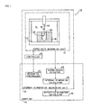
- Fig. 1 shows an outline structure of a screw measuring apparatus 10 that uses a screw measuring method according to an embodiment of the present invention.
- the screw measuring apparatus 10 includes a coordinate measuring unit 12 and a screw measuring probe 14.
- the coordinate measuring unit 12 is formed of a computer-numerical-control (CNC) three-dimensional measuring unit.
- a female screw 16 is placed in the coordinate measuring unit 12. The female screw 16 and the screw measuring probe 14 can be moved relatively to each other.
- the screw measuring probe 14 is attached to the coordinate measuring unit 12.
- the screw measuring probe 14 is formed of a probe body 18 and a stylus 20.
- the probe body 18 is provided so as to be movable relatively to the female screw 16, placed in the coordinate measuring unit 12.
- the probe body 18 detects coordinate information on the female screw 16.
- the stylus 20 is attached to the probe body 18.
- the stylus 20 has a stylus-tip sphere 22 at the tip of the stylus 20.
- the stylus-tip sphere 22 has an optimal diameter selected according to the pitch of the female screw 16.
- the screw measuring probe which includes the stylus 20, serves as a profiling probe. While the stylus-tip sphere 22 of the probe is butt against the wall surface of the female screw and is moved along the axis of the female screw, coordinate information about the wall surface of the female screw is obtained at constant intervals to measure the female-screw shape characteristics.
- the screw measuring apparatus 10 also includes an internal-dimension measuring unit 30 and an effective-diameter calculator 32.
- the internal-dimension measuring unit 30 calculates internal-dimension information D w from the coordinate information obtained when the stylus-tip sphere 22, having a diameter selected according to the pitch of the female screw 16, is butt against the groove of the female screw 16.
- This internal-dimension information D w is equal to the diameter of a cylinder having the same center axial line as the female screw 16 and having a wall that passes through the center of the stylus-tip sphere 22 when the stylus-tip sphere 22 is butt against the groove of the female screw 16.
- the effective-diameter calculator 32 calculates effective-diameter information D e of the female screw 16 from the internal-dimension information D w calculated by the internal-dimension measuring unit 30, diameter information 2r of the stylus-tip sphere 22, and thread-angle information ⁇ and pitch information P of the female screw 16.
- the internal-dimension measuring unit 30 includes a measurement controller 34, a screw-groove detector 36, and an internal-dimension calculator 38.
- the measurement controller 34 specifies movement along each axis and controls measurement operations in the coordinate measuring unit 12.
- the measurement controller 34 controls the coordinate measuring unit 12 such that the stylus-tip sphere 22 is made to crawl on the wall surface of the female screw 16 along the screw axis to detect the maximum displacement of the stylus-tip sphere 22 in the outer radial direction of the female screw 16.
- the screw-groove detector 36 performs screw-groove detection at two or more (for example, three) measurement positions separated by a predetermined angle in the circumferential direction on the wall surface of the female screw 16.
- the screw-groove detection based on coordinate information obtained when the stylus-tip sphere 22 is made to crawl on the wall surface of the female screw 16 along the screw axis, the maximum displacement of the stylus-tip sphere 22 in the outer radial direction of the female screw 16. It is assumed that the stylus-tip sphere 22 is completely fitted in the screw groove of the female screw 16 at the maximum displacement.
- the internal-dimension calculator 38 obtains the internal-dimension information D w from coordinate information of each screw groove detected by the screw-groove detector 36.
- the internal-dimension information D w indicates the diameter of the cylinder.
- the screw measuring probe 14 In order to perform relative movement between the screw measuring probe 14 and the female screw 16 in the axial-line directions (Z-axis directions) of the female screw 16 and the directions (X and Y axis directions) perpendicular to the axial line of the female screw 16, the screw measuring probe 14 is attached to a Z-axis spindle 40 of the coordinate measuring unit 12. The screw measuring probe 14 can be moved relative to the coordinate measuring unit 12 in the X, Y, and Z axis directions. In order to make the Z axis directions of the coordinate measuring unit 12 and the axial-line directions of the female screw 16 parallel, the female screw 16 is placed on a table 42 of the coordinate measuring unit 12.
- a computer 44 and a controller 46 are provided to make the screw measuring apparatus 10 automatically execute each of the above-described processes.
- the computer 44 controls the operation of the coordinate measuring unit 12 and performs data processing.
- the controller 46 is provided between the computer 44 and the coordinate measuring unit 12 and operates the coordinate measuring unit 12 according to instructions sent from the computer 44.
- the outline configuration of the screw measuring apparatus 10 is as described above. The operation thereof will be described below.
- the internal dimension D w is measured with the screw measuring probe, having the stylus at the tip of which the stylus-tip sphere 22 having the diameter selected according to the pitch of the female screw is attached.
- Fig. 2 is a cross-sectional view of a part of the female screw 16, including the axial line 50 of the female screw 16.
- the effective diameter D e of the female screw 16 is obtained by the above-described effective-diameter calculation expression.
- the internal dimension D w of the female screw 16 is equal to the diameter of a cylinder 54 having a center axial line 52 identical with the axial line 50 of the female screw 16 and having the wall surface that passes through the center of the stylus-tip sphere 22 when the stylus-tip sphere 22 having a diameter of 2r is butted against the screw groove of the female screw 16.
- the effective diameter D e of the female screw 16 is equal to the diameter of a cylinder 56 having the wall surface that passes through points of the female screw 16, where the width of the thread and the width of the groove match.
- an internal-dimension measuring process S10 and an effective-diameter calculating process S 12 are provided.
- the internal-dimension information D w is obtained from coordinate information measured when the stylus-tip sphere 22 is butted against the female screw 16.
- the internal dimension D w is equal to the diameter of a cylinder having a center axial line identical with the axial line 50 of the female screw 16 and having the wall surface that passes through the center of the stylus-tip sphere 22 when the stylus-tip sphere 22 is butted against the screw groove of the female screw 16.
- the effective-diameter information D e of the female screw 16 is obtained from the internal-dimension information D w calculated in the internal-dimension measuring process S10, diameter information 2r of the stylus-tip sphere 22, and thread-angle information ⁇ and pitch information P of the female screw 16.
- the internal-dimension measuring process S10 is formed of a screw-groove detecting process S 14 and an internal-dimension calculating process S16.
- the stylus 20 is inserted into the screw hole of the female screw 16 in the screw-groove detecting process S14, as shown in Fig. 3A.
- the stylus-tip sphere 22 is pushed into a perfectly threaded portion, for example, the fourth screw-valley from the top of the screw hole of the female screw 16, as shown in Fig. 3B.
- the wall surface of the screw hole is traced with the stylus-tip sphere 22, as shown in Fig. 3C. While the stylus-tip sphere 22 is pushed against the wall surface of the screw hole, the stylus-tip sphere 22 is moved along the axial line of the female screw 16 (along the Z axis). It is assumed that the stylus-tip sphere 22 completely falls in the screw groove (valley) of the female screw 16 at the maximum displacement toward the outside in the radial direction of the screw hole.
- This measurement is performed at three or more points separated in the circumferential direction on the wall surface of the screw hole. As shown in Fig. 3D, in a view from the top of the screw hole, the measurement is performed at three measurement points 60, 62, and 64, separated in the circumferential direction of the screw groove.
- the diameter of the cylinder is acquired to obtain the internal-dimension information D w in the internal-dimension calculating process S16.
- the effective diameter D e is obtained by the effective-diameter calculation expression from the internal dimension D w , measured with the stylus-tip sphere 22 being actually butted against the female screw 16.
- the effective diameter of a female screw can be automatically measured more accurately in the present invention than in a case where a combination of an actual internal-dimension measurement, with the stylus-tip sphere having a diameter optimal to the pitch of the female screw, and effective-diameter calculation by the use of the effective-diameter calculation expression is not taken into account.
- the effective diameter of a female screw can be automatically measured accurately with a CNC three-dimensional measuring machine.
- the present invention provides higher measurement efficiency than in manual measurement with a female-screw gauge.
- the effective diameter of the female screw 16 can be automatically measured with highly-increased accuracy.
- the accuracy of the effective-diameter measurement can be significantly improved compared with a case where the diameter 2r of the stylus-tip sphere 22 is not taken into account.
- the present inventors performed extensive examination of automatic measurement of female-screw effective diameters and found the following points.
- an error might occur when an actual female-screw shape is converted (changed by approximation) to a virtual female-screw shape.
- an error might occur when an actual shape of a stylus-tip sphere is changed by approximation to a virtual shape of the stylus-tip sphere. Therefore, actual measurement performed when the stylus-tip sphere contacts with the actual female screw differs from simulation performed with contact between a virtual female-screw shape and a virtual shape of the stylus-tip sphere.
- the present inventors found that the combination of the following points is very effective. Specifically, without performing virtual screw measurement, an internal dimension of a female screw is measured while a screw measuring probe of a three-dimensional measuring machine is actually butted against the female screw, and the effective diameter of the female screw is calculated by the above-described effective-diameter calculation expression.
- the present inventors also found that, just by direct measurement of an internal dimension, it was difficult to improve the accuracy to a desired level.
- the present inventors found that it is very effective to use a screw measuring probe that has a stylus-tip sphere having an optimal diameter which is selected such that the influence of an error that would adversely affect the measurement result of the effective diameter of a female screw is minimized.
- the present inventors have completed the present invention.
- Fig. 4A shows the whole of the L-shaped stylus 20.
- Fig. 4B is an enlarged view of the L-shaped stylus 20.
- Fig. 4C shows a measurement procedure with the L-shaped stylus 20.
- the stylus 20 preferably has an L shape, as shown in Fig. 4A.
- the L-shaped stylus 20 includes a body-side stylus shaft 70 and a tip-side stylus shaft 72.
- the body-side stylus shaft 70 has a stylus axial line that matches the axial line of the female screw.
- the tip-side stylus shaft 72 is perpendicular to the body-side stylus shaft 70 and has a stylus-tip sphere 22 at its tip.
- the detector include strain gauges 74a and 74b in order to automatically measure the effective diameter of a female screw more appropriately.
- the strain gauges 74a and 74b are provided for the body-side stylus shaft 70.
- the strain gauges 74a and 74b detect strain information (direction and displacement) in the directions of the tip-side stylus shaft 72.
- coordinate information for example, position information or displacement information of the stylus-tip sphere 22 in a radial direction of the female screw (along the X axis or the Y axis) is detected.
- the screw measuring probe When measurement is finished at a measurement point, the screw measuring probe can be rotated to perform the same measurement at three or more measurement points easily with the use of the L-shaped stylus, shown in Fig. 4A to Fig. 4C.
- Fig. 5A shows the whole of the cross-shaped stylus.
- Fig. 5B is an enlarged view of the cross-shaped stylus.
- Fig. 5C shows a measurement procedure with the cross-shaped stylus.
- the stylus have a cross shape such that the stylus-tip sphere does not interfere with the thread when the stylus-tip sphere contacts the screw groove (valley) of the female screw in measurement.
- the cross-shaped stylus includes a body-side stylus shaft 70 and four tip-side stylus shafts 72a, 72b, 72c, and 72d.
- the body-side stylus shaft 70 extends in the axial-line directions of the female screw.
- the tip-side stylus shafts 72a, 72b, 72c, and 72d are respectively perpendicular to the body-side stylus shaft 70 and are separated from each other by 90 degrees in a plane perpendicular to the axial-line directions of the female screw.
- strain gauges be included as detectors in order to automatically measure the effective diameter of a female screw more appropriately.
- strain gauges 74a and 74b for detecting strain information along the X axis and strain gauges 74c and 74d for detecting strain information along the Y axis are provided in an example case.
- measurement at a measurement point 60 with the use of a stylus-tip sphere 22a, measurement at a measurement point 62 with the use of a stylus-tip sphere 22b, and measurement at a measurement point 64 with the use of a stylus-tip sphere 22c can be sequentially performed.
- the cross-shaped stylus shown in Fig. 5A to Fig. 5C allows very-accurate and easy measurement of an internal dimension. Therefore, the effective diameter is also measured accurately and more easily.
- the cross-shaped stylus allows quick measurement at more measurement points without rotating the stylus, it can perform measurement more efficiently than the L-shaped stylus.
- scales are also preferably used as detectors.
- a case in which a virtual cylinder is obtained from coordinate information on a female screw and an internal dimension of the female screw is obtained from the diameter of the cylinder has been described.
- the present invention is not limited to this case. It is also preferred that the internal dimension be directly obtained.
- the distance between the center position of the stylus-tip sphere obtained when the stylus-tip sphere is butted against the screw groove (valley) of the female screw at a first measurement point, and the center position of the stylus-tip sphere obtained when the stylus-tip sphere is butted against the screw groove (valley) at a second measurement point opposite the first measurement point, separated by 180 degrees with respect to the axial line of the female screw is obtained to directly acquire the internal dimension.
- the effective diameter of a female screw can be directly calculated by direct measurement with a screw measuring probe having a stylus-tip sphere that has an optimal diameter selected according to the pitch of the female screw, without obtaining a large amount of shape data.
- the accuracy of automatic measurement of the effective diameter of a female screw with the use of a three-dimensional measuring machine can be more largely improved.
- a screw measuring probe that includes a stylus-tip sphere having a diameter selected according to the pitch of a female screw and effective-diameter calculation by the above-described effective-diameter calculation expression according to the present invention can be applied to the technology disclosed in Japanese Unexamined Patent Application Publication No. 2001-82952 to measure screw-shape characteristics other than the effective diameter of the female screw, such as the effective diameter and effective depth of a male screw.
Landscapes
- Physics & Mathematics (AREA)
- General Physics & Mathematics (AREA)
- A Measuring Device Byusing Mechanical Method (AREA)
- Length Measuring Devices With Unspecified Measuring Means (AREA)
Abstract
Description
- The present invention relates to screw measuring methods, screw measuring probes, and screw measuring apparatuses using the screw measuring probes, and more particularly, to an improvement of an automatic method (mechanism) for measuring the effective diameter of a female screw.
- Screws have been conventionally used to clamp various components. Since screws largely affect the quality and life time of the entire product in which the screws are used, it is very important to inspect them to maintain the quality thereof in a manufacturing process for machining them precisely. In screw inspection, characteristic values of the shape of each screw are measured, such as the effective depth, the pitch, the effective diameter, the thread angle, and the threading length.
- For example, the three-wire method is often used to measure the effective diameter of a male screw. In the three-wire method, a three-wire gauge is applied to the groove of the male screw, the external dimension is measured with a micrometer, and the effective diameter of the male screw is obtained from the measured external dimension.
- Since the three-wire method is a manual measurement method, skill in handling a three-wire gauge is required. Because micrometer readings may differ from operator to operator, it is difficult to maintain measurement precision and the efficiency of the measurement work.
- Therefore, simplified measurement has been demanded in the field of screw measurement. To satisfy such a demand, a measurement method of measuring the dimensions of various shape characteristics of screws by the use of a three-dimensional measurement machine has been proposed (such as that disclosed in
Japanese Unexamined Patent Application Publication No. 2001-82952 - In the method described in
Japanese Unexamined Patent Application Publication No. 2001-82952 - Even with the method described in
Japanese Unexamined Patent Application Publication No. 2001-82952 - Conventionally, there is no suitable conventional technology to solve this issue. Although a three-dimensional measurement machine has been used to measure the effective diameter of a female screw, an appropriate machine for automatic measurement of the effective diameter of a female screw has not been developed.
- The present invention has been made in view of the foregoing situation. Accordingly, it is an object of the present invention to provide a screw measuring method, a screw measuring probe, and a screw measuring apparatus using the screw measuring probe, all capable of performing accurate automatic measurement of the effective diameter of a female screw.
- The present inventors performed extensive examination of automatic measurement of the effective diameters of female screws, found that a combination of the following points largely improves the accuracy of automatic measurement of the effective diameters of female screws, and have thus realized the present invention. Specifically, an internal dimension of a female screw is actually measured with a stylus-tip sphere having a diameter optimal for the pitch of the female screw, and the effective diameter of the female screw is calculated by an effective-diameter calculation expression described below.
- In order to achieve the object described above, a screw measuring method according to the present invention includes an internal-dimension measuring step and an effective-diameter calculating step.
- The internal-dimension measuring step uses a coordinate measuring machine provided with a screw measuring probe that has a stylus-tip sphere having a diameter selected according to the pitch of a female screw to measure internal-dimension information Dw equal to the diameter of a cylinder having a center axial line identical with the axial line of the female screw and having a wall that passes through the center of the stylus-tip sphere when the stylus-tip sphere is butted against the screw groove of the female screw, based on coordinate information measured while the stylus-tip sphere is butted against the screw groove of the female screw.
- The effective-diameter calculating step obtains effective-diameter information De of the female screw from the internal-dimension information Dw measured in the internal-dimension measuring step,
diameter information 2r of the stylus-tip sphere, and thread angle information α and pitch information P of the female screw, by using an effective-diameter calculation expression De = Dw + 2r x cosec(α/2) - (P/2) x cot(α/2). - In the present invention, it is preferred that the internal-dimension measuring step includes a screw-groove detecting step, and an internal-dimension calculating step.
- The screw-groove detecting step detects the screw groove at two or more measurement points separated by a predetermined angle circumferentially on the wall surface of the female screw, when the stylus-tip sphere is at a maximum displacement point toward the outside in the radial direction of the female screw while the stylus-tip sphere contacts the wall surface of the female screw and the stylus-tip sphere is made to crawl along the axial line of the female screw, the maximum displacement point being regarded as a point where the stylus-tip sphere completely falls in the screw groove of the female screw.
- The internal-dimension calculating step obtains the internal-dimension information Dw according to coordinate information on each screw groove detected in the screw-groove detecting step.
- In order to achieve the object described above, a screw measuring probe according to the present invention, provided for a coordinate measuring machine and used for measuring the effective diameter of a female screw, includes a probe body, a stylus, and a detector.
- The probe body is provided in a movable manner relative to a female screw placed on the coordinate measuring machine;
- The stylus comprises a stylus shaft provided for the probe body and a stylus-tip sphere provided at a tip of the stylus shaft and having a diameter selected according to the pitch of the female screw.
- The detector is provided for the probe body or the stylus, detects coordinate information related to the female screw.
- In the present invention, it is preferred that the
diameter 2r of the stylus-tip sphere is given by anexpression 2r = P/(2cosα/2), where P indicates the pitch of the female screw and α indicates the thread angle of the female screw. - The inventors found that, when actually measuring the effective diameter of a female screw with a stylus having a stylus-tip sphere, the stylus-tip sphere is tilted in the directions of the lead angle of the screw thread and sometimes contacts not the slope of the screw thread in a cross-sectional plane of the axis of the female screw but a point shifted from the cross-sectional plane of the female screw. Since elastic deformation may occur between the stylus-tip sphere, and the screw thread and measurement plane, it was confirmed that an error could occur in a measurement result obtained when the stylus-tip sphere actually made contact with the female screw. It was also confirmed that an error could occur in a parameter included in the female-screw effective-diameter calculation expression. The present inventors found that it is very important to reduce the influence of an error that would adversely affect the measurement result of the effective diameter of the female screw in order to dramatically increase the accuracy of automatic measurement of the effective diameter of the female screw. It was found that, when an optimal diameter was selected for the stylus-tip sphere, especially when the stylus-tip sphere had a
diameter 2r represented by theexpression 2r = P/(2cosα/2), the influence of the error on the measurement result obtained when the stylus-tip sphere actually made contact with the female screw was largely reduced. - In the present invention, it is preferred that the stylus shaft comprises a body-side stylus shaft portion and a tip-side stylus shaft portion.
- The body-side stylus shaft portion has a stylus axial line identical with the axial line of the female screw.
- The tip-side stylus shaft portion perpendicular to the body-side stylus shaft portion, has a stylus axial line parallel to detection directions of the coordinate information, and has the stylus-tip sphere at a tip.
- In the present invention, it is preferred that the detector comprises a strain gauge or a scale.
- The strain gauge or the scale is provided for the probe body or the stylus shaft, detects the coordinate information related to the female screw.
- In order to achieve the object described above, a screw measuring apparatus according to the present invention includes the screw measuring probe, a coordinate measuring machine, an internal-dimension measuring unit, and an effective-diameter calculating unit.
- The coordinate measuring machine in which the female screw is placed such that the female screw and the screw measuring probe move relatively to each other, is used.
- The internal-dimension measuring unit obtains internal-dimension information Dw equal to the diameter of a cylinder having a center axial line identical with the axial line of the female screw and having a wall that passes through the center of the stylus-tip sphere when the stylus-tip sphere is butted against the screw groove of the female screw, based on coordinate information measured while the stylus-tip sphere is butted against the screw groove of the female screw.
- The effective-diameter calculating unit obtains effective-diameter information De of the female screw from the internal-dimension information Dw obtained by the internal-dimension measuring unit,
diameter information 2r of the stylus-tip sphere, and thread angle information α and pitch information P of the female screw, by using an effective-diameter calculation expression De = Dw + 2r x cosec(α/2) - (P/2) x cot(α/2). - The effective diameter of a female screw means the average of diameters obtained from portions where a male screw and the female screw contact. In other words, the effective diameter of the female screw equals the diameter of a cylinder whose wall passes through points where the thread width and the groove width are equal in the female screw.
- In the present invention, the number of threads can be used instead of the pitch P.
- A screw measuring method of the present invention includes an internal-dimension measuring step of measuring an internal dimension by actually butting a stylus-tip sphere having a diameter corresponding to the pitch of a female screw against the screw groove of the female screw, and an effective-diameter calculating step of obtaining the effective diameter of the female screw by using an effective-diameter calculation expression. Therefore, the effective diameter of the female screw can be automatically measured accurately.
- According to a screw measuring probe of the present invention, a stylus-tip sphere having a diameter corresponding to the pitch of a female screw is provided. Therefore, the effective diameter of the female screw can be automatically measured accurately.
- In the screw measuring probe of the present invention, when the
diameter 2r of the stylus-tip sphere is given by theexpression 2r = P/(2cosα/2), where P indicates the pitch of the female screw and α indicates the thread angle of the female screw, the effective diameter of the female screw can be automatically measured more accurately. - When the screw measuring probe of the present invention has an L-shaped stylus or a cross-shaped stylus, the effective diameter of the female screw can be automatically measured more easily.
- According to a screw measuring apparatus of the present invention, a screw measuring probe according to the present invention, a coordinate measuring machine, an internal-dimension measuring unit for obtaining an internal dimension by actually butting the screw measuring probe against the screw groove of a female screw, and an effective-diameter calculating unit for obtaining the effective diameter of the female screw by using an effective-diameter calculation expression are provided. Therefore, the effective diameter of the female screw can be automatically measured accurately.
-
- Fig. 1 is a view showing an outline structure of a screw measuring apparatus according to an embodiment of the present invention.
- Fig. 2 is a view showing an internal dimension and an effective diameter of a female screw in the embodiment.
- Fig. 3A to Fig. 3C show a flowchart of a processing procedure of a screw measuring method according to the embodiment. Fig. 3D shows measurement points.
- Fig. 4A to Fig. 4C show a screw measuring probe having an L-shaped stylus in the embodiment.
- Fig. 5A to Fig. 5C show a screw measuring probe having a cross-shaped stylus in the embodiment.
- A preferred embodiment of the present invention will be described below by referring to the drawings.
- Fig. 1 shows an outline structure of a
screw measuring apparatus 10 that uses a screw measuring method according to an embodiment of the present invention. - In Fig. 1, the
screw measuring apparatus 10 includes a coordinate measuringunit 12 and ascrew measuring probe 14. - The coordinate measuring
unit 12 is formed of a computer-numerical-control (CNC) three-dimensional measuring unit. Afemale screw 16 is placed in the coordinate measuringunit 12. Thefemale screw 16 and thescrew measuring probe 14 can be moved relatively to each other. - The
screw measuring probe 14 is attached to the coordinate measuringunit 12. Thescrew measuring probe 14 is formed of aprobe body 18 and astylus 20. - The
probe body 18 is provided so as to be movable relatively to thefemale screw 16, placed in the coordinate measuringunit 12. Theprobe body 18 detects coordinate information on thefemale screw 16. - The
stylus 20 is attached to theprobe body 18. Thestylus 20 has a stylus-tip sphere 22 at the tip of thestylus 20. The stylus-tip sphere 22 has an optimal diameter selected according to the pitch of thefemale screw 16. - In the present embodiment, the screw measuring probe, which includes the
stylus 20, serves as a profiling probe. While the stylus-tip sphere 22 of the probe is butt against the wall surface of the female screw and is moved along the axis of the female screw, coordinate information about the wall surface of the female screw is obtained at constant intervals to measure the female-screw shape characteristics. - The
screw measuring apparatus 10 also includes an internal-dimension measuring unit 30 and an effective-diameter calculator 32. - In an internal-dimension measuring process, the internal-
dimension measuring unit 30 calculates internal-dimension information Dw from the coordinate information obtained when the stylus-tip sphere 22, having a diameter selected according to the pitch of thefemale screw 16, is butt against the groove of thefemale screw 16. This internal-dimension information Dw is equal to the diameter of a cylinder having the same center axial line as thefemale screw 16 and having a wall that passes through the center of the stylus-tip sphere 22 when the stylus-tip sphere 22 is butt against the groove of thefemale screw 16. - In an effective-diameter calculating process, the effective-
diameter calculator 32 calculates effective-diameter information De of thefemale screw 16 from the internal-dimension information Dw calculated by the internal-dimension measuring unit 30,diameter information 2r of the stylus-tip sphere 22, and thread-angle information α and pitch information P of thefemale screw 16. Specifically, the effective-diameter information De is obtained by the following effective-diameter calculation expression:
- The internal-
dimension measuring unit 30 includes a measurement controller 34, a screw-groove detector 36, and an internal-dimension calculator 38. - The measurement controller 34 specifies movement along each axis and controls measurement operations in the coordinate measuring
unit 12. The measurement controller 34 controls the coordinate measuringunit 12 such that the stylus-tip sphere 22 is made to crawl on the wall surface of thefemale screw 16 along the screw axis to detect the maximum displacement of the stylus-tip sphere 22 in the outer radial direction of thefemale screw 16. - In a screw-groove detecting process, the screw-
groove detector 36 performs screw-groove detection at two or more (for example, three) measurement positions separated by a predetermined angle in the circumferential direction on the wall surface of thefemale screw 16. In the screw-groove detection, based on coordinate information obtained when the stylus-tip sphere 22 is made to crawl on the wall surface of thefemale screw 16 along the screw axis, the maximum displacement of the stylus-tip sphere 22 in the outer radial direction of thefemale screw 16. It is assumed that the stylus-tip sphere 22 is completely fitted in the screw groove of thefemale screw 16 at the maximum displacement. - In an internal-dimension calculating process, the internal-
dimension calculator 38 obtains the internal-dimension information Dw from coordinate information of each screw groove detected by the screw-groove detector 36. The internal-dimension information Dw indicates the diameter of the cylinder. - In order to perform relative movement between the
screw measuring probe 14 and thefemale screw 16 in the axial-line directions (Z-axis directions) of thefemale screw 16 and the directions (X and Y axis directions) perpendicular to the axial line of thefemale screw 16, thescrew measuring probe 14 is attached to a Z-axis spindle 40 of the coordinate measuringunit 12. Thescrew measuring probe 14 can be moved relative to the coordinate measuringunit 12 in the X, Y, and Z axis directions. In order to make the Z axis directions of the coordinate measuringunit 12 and the axial-line directions of thefemale screw 16 parallel, thefemale screw 16 is placed on a table 42 of the coordinate measuringunit 12. - A
computer 44 and a controller 46 are provided to make thescrew measuring apparatus 10 automatically execute each of the above-described processes. - The
computer 44 controls the operation of the coordinate measuringunit 12 and performs data processing. - The controller 46 is provided between the
computer 44 and the coordinate measuringunit 12 and operates the coordinate measuringunit 12 according to instructions sent from thecomputer 44. - The outline configuration of the
screw measuring apparatus 10 is as described above. The operation thereof will be described below. - In the present embodiment, the internal dimension Dw, shown in Fig. 2, is measured with the screw measuring probe, having the stylus at the tip of which the stylus-
tip sphere 22 having the diameter selected according to the pitch of the female screw is attached. Fig. 2 is a cross-sectional view of a part of thefemale screw 16, including theaxial line 50 of thefemale screw 16. The effective diameter De of thefemale screw 16 is obtained by the above-described effective-diameter calculation expression. - The internal dimension Dw of the
female screw 16 is equal to the diameter of acylinder 54 having a centeraxial line 52 identical with theaxial line 50 of thefemale screw 16 and having the wall surface that passes through the center of the stylus-tip sphere 22 when the stylus-tip sphere 22 having a diameter of 2r is butted against the screw groove of thefemale screw 16. - The effective diameter De of the
female screw 16 is equal to the diameter of acylinder 56 having the wall surface that passes through points of thefemale screw 16, where the width of the thread and the width of the groove match. - As shown in Fig. 3, an internal-dimension measuring process S10 and an effective-diameter
calculating process S 12 are provided. - In the internal-dimension measuring process S10, the internal-dimension information Dw is obtained from coordinate information measured when the stylus-
tip sphere 22 is butted against thefemale screw 16. The internal dimension Dw is equal to the diameter of a cylinder having a center axial line identical with theaxial line 50 of thefemale screw 16 and having the wall surface that passes through the center of the stylus-tip sphere 22 when the stylus-tip sphere 22 is butted against the screw groove of thefemale screw 16. - In the effective-diameter calculating process S12, the effective-diameter information De of the
female screw 16 is obtained from the internal-dimension information Dw calculated in the internal-dimension measuring process S10,diameter information 2r of the stylus-tip sphere 22, and thread-angle information α and pitch information P of thefemale screw 16. Specifically, the effective-diameter information De is obtained by the following effective-diameter calculation expression:
- The internal-dimension measuring process S10 is formed of a screw-groove detecting
process S 14 and an internal-dimension calculating process S16. - In the internal-dimension measuring process S10, while the stylus-
tip sphere 22 is in contact with the wall surface of thefemale screw 16, when the stylus-tip sphere 22 is made to crawl in the axial directions of thefemale screw 16, the maximum displacement of the stylus-tip sphere 22 in the outer radial direction (X direction or Y direction) of thefemale screw 16 is detected. It is assumed that the stylus-tip sphere 22 is completely fitted in the screw groove (valley) of thefemale screw 16 at the maximum displacement. - More specifically, the
stylus 20 is inserted into the screw hole of thefemale screw 16 in the screw-groove detecting process S14, as shown in Fig. 3A. - Then, the stylus-
tip sphere 22 is pushed into a perfectly threaded portion, for example, the fourth screw-valley from the top of the screw hole of thefemale screw 16, as shown in Fig. 3B. - The wall surface of the screw hole is traced with the stylus-
tip sphere 22, as shown in Fig. 3C. While the stylus-tip sphere 22 is pushed against the wall surface of the screw hole, the stylus-tip sphere 22 is moved along the axial line of the female screw 16 (along the Z axis). It is assumed that the stylus-tip sphere 22 completely falls in the screw groove (valley) of thefemale screw 16 at the maximum displacement toward the outside in the radial direction of the screw hole. - This measurement is performed at three or more points separated in the circumferential direction on the wall surface of the screw hole. As shown in Fig. 3D, in a view from the top of the screw hole, the measurement is performed at three
measurement points - Based on coordinate information at
screw groove portions process S 14, the diameter of the cylinder is acquired to obtain the internal-dimension information Dw in the internal-dimension calculating process S16. - The effective diameter De is obtained by the effective-diameter calculation expression from the internal dimension Dw, measured with the stylus-
tip sphere 22 being actually butted against thefemale screw 16. - As a result, the effective diameter of a female screw can be automatically measured more accurately in the present invention than in a case where a combination of an actual internal-dimension measurement, with the stylus-tip sphere having a diameter optimal to the pitch of the female screw, and effective-diameter calculation by the use of the effective-diameter calculation expression is not taken into account.
- For example, the effective diameter of a female screw can be automatically measured accurately with a CNC three-dimensional measuring machine.
- Since measurement is performed automatically, the present invention provides higher measurement efficiency than in manual measurement with a female-screw gauge.
- When measurement of the effective diameter of a female screw according to the present invention is performed in a manufacturing process for machining female screws at high precision, quantitative management of the effective diameters of the female screws can be performed accurately and easily.
- To measure the effective diameter of a female screw automatically and more accurately, it is preferred that the
diameter 2r of the stylus-tip sphere 22 of thescrew measuring probe 14 satisfy theexpression 2r = P/(2cosα/2). - Specific preferred examples of the relationship between the diameter (2r) of the stylus-
tip sphere 22 and the metric-screw pitch (P) of the female screw 16 (and the number (N) of unified-screw threads) will be indicated below.<Table 1> 2r(mm) 0.1155 0.1443 0.1732 0.2021 0.2309 0.2598 0.2887 0.3464 0.4041 P (mm) 0.2 0.25 0.3 0.35 0.4 0.45 0.5 0.6 0.7 N - - 80 72 64 56 48 44,40 36 2r(mm) 0.4330 0.4619 0.5196 0.5774 0.7217 0.7536 0.7964 0.8949 1.0227 P (mm) 0.75 0.8 - 1 1.25 - - 1.5 1.75 N - 32 28 24 20 - 18 16 14 2r(mm) 1.1547 1.1932 1.3016 1.4434 1.5908 1.7897 2.0454 2.3863 2.5981 P (mm) 2 - - 2.5 - 3 3.5 4 4.5 N 13 12 11 10 9 8 7 6 - 2r(mm) 2.8868 3.1817 3.4641 3.594 P (mm) 5 5.5 6 - N 5 4 1/2 - 4 - According to the present invention, only when the
diameter 2r of the stylus-tip sphere 22 is optimized according to the shape of thefemale screw 16 and effective-diameter calculation is also performed with the use of the effective-diameter calculation expression, the effective diameter of thefemale screw 16 can be automatically measured with highly-increased accuracy. In other words, when thediameter 2r of the stylus-tip sphere 22 is taken into account, the accuracy of the effective-diameter measurement can be significantly improved compared with a case where thediameter 2r of the stylus-tip sphere 22 is not taken into account. - Even conventionally, as disclosed in
Japanese Unexamined Patent Application Publication No. 2001-82952 - The present inventors performed extensive examination of automatic measurement of female-screw effective diameters and found the following points.
- In conventional screw-shape measurement using a three-dimensional measuring machine, measurement is basically performed with image processing. From profiling measurement results, a virtual screw shape is generated. In image processing, a virtual three-wire gauge is applied to the virtual screw shape to obtain the effective diameter of the screw, which is usually performed in the field.
- It was also found that a measurement error occurred when actual screw measurement was shifted to virtual screw measurement performed with image processing.
- More specifically, an error might occur when an actual female-screw shape is converted (changed by approximation) to a virtual female-screw shape. In addition, an error might occur when an actual shape of a stylus-tip sphere is changed by approximation to a virtual shape of the stylus-tip sphere. Therefore, actual measurement performed when the stylus-tip sphere contacts with the actual female screw differs from simulation performed with contact between a virtual female-screw shape and a virtual shape of the stylus-tip sphere.
- Even though an error occurs between the actual screw measurement and the virtual screw measurement, correcting the error has not been taken into account conventionally. In addition, such a correction is very difficult to perform. It was found that the error could have prevented an improvement in accuracy when the effective diameter of a female screw was performed by the use of a three-dimensional measuring machine.
- To improve accuracy in the automatic measurement of the effective diameter of a female screw with the use of a three-dimensional measuring machine, the present inventors found that the combination of the following points is very effective. Specifically, without performing virtual screw measurement, an internal dimension of a female screw is measured while a screw measuring probe of a three-dimensional measuring machine is actually butted against the female screw, and the effective diameter of the female screw is calculated by the above-described effective-diameter calculation expression.
- The present inventors also found that, just by direct measurement of an internal dimension, it was difficult to improve the accuracy to a desired level. The present inventors found that it is very effective to use a screw measuring probe that has a stylus-tip sphere having an optimal diameter which is selected such that the influence of an error that would adversely affect the measurement result of the effective diameter of a female screw is minimized. As a result of these findings, the present inventors have completed the present invention.
- Some details of the reasons of improving accuracy in female-screw effective diameter measurement have not yet been known. The present inventors think that, since an internal dimension of a female screw is actually measured by using a screw measuring probe that has a stylus-tip sphere having an optimal diameter which is selected such that the influence of an error that would adversely affect the measurement result of the effective diameter of the female screw is minimized, reproducibility (accuracy) in appropriate contact position of the stylus-tip sphere on the screw groove (valley) of the female screw is improved.
- It is also very important to design the shape of the stylus used, in order to make the measurement of the effective diameter of a female screw easier.
- In the measurement of the effective diameter of a female screw, because the stylus-tip sphere contacts the screw groove (valley) of the female screw, it is important that the stylus shaft should not interfere with the thread.
- An L-shaped
stylus 20 shown in Fig. 4A to Fig. 4C, which is very important, is employed. - Fig. 4A shows the whole of the L-shaped
stylus 20. Fig. 4B is an enlarged view of the L-shapedstylus 20. Fig. 4C shows a measurement procedure with the L-shapedstylus 20. - The
stylus 20 preferably has an L shape, as shown in Fig. 4A. The L-shapedstylus 20 includes a body-side stylus shaft 70 and a tip-side stylus shaft 72. The body-side stylus shaft 70 has a stylus axial line that matches the axial line of the female screw. The tip-side stylus shaft 72 is perpendicular to the body-side stylus shaft 70 and has a stylus-tip sphere 22 at its tip. - In Fig. 4A, it is preferred that the detector include
strain gauges side stylus shaft 70. The strain gauges 74a and 74b detect strain information (direction and displacement) in the directions of the tip-side stylus shaft 72. - Based on the strain information detected by the
strain gauges tip sphere 22 in a radial direction of the female screw (along the X axis or the Y axis) is detected. - When measurement is finished at a measurement point, the screw measuring probe can be rotated to perform the same measurement at three or more measurement points easily with the use of the L-shaped stylus, shown in Fig. 4A to Fig. 4C.
- When measurement is performed at three
measurement points - It is also important that a cross-shaped stylus shown in Fig. 5A to Fig. 5C be employed instead of the L-shaped stylus.
- Fig. 5A shows the whole of the cross-shaped stylus. Fig. 5B is an enlarged view of the cross-shaped stylus. Fig. 5C shows a measurement procedure with the cross-shaped stylus.
- As shown in Fig. 5A to Fig. 5C, it is also preferred that the stylus have a cross shape such that the stylus-tip sphere does not interfere with the thread when the stylus-tip sphere contacts the screw groove (valley) of the female screw in measurement. The cross-shaped stylus includes a body-
side stylus shaft 70 and four tip-side stylus shafts side stylus shaft 70 extends in the axial-line directions of the female screw. The tip-side stylus shafts side stylus shaft 70 and are separated from each other by 90 degrees in a plane perpendicular to the axial-line directions of the female screw. - It is also preferred in the screw measuring probe having the cross-shaped stylus shown in Fig. 5A that strain gauges be included as detectors in order to automatically measure the effective diameter of a female screw more appropriately.
- In Fig. 5A,
strain gauges strain gauges - With the use of the cross-shaped stylus shown in Fig. 5A to Fig. 5C, measurement can be easily performed at four measurement points without rotating the screw measuring probe.
- As shown in Fig. 5C, for example, without rotating the screw measuring probe, measurement at a
measurement point 60 with the use of a stylus-tip sphere 22a, measurement at ameasurement point 62 with the use of a stylus-tip sphere 22b, and measurement at ameasurement point 64 with the use of a stylus-tip sphere 22c can be sequentially performed. - Like the above-described L-shaped stylus, the cross-shaped stylus shown in Fig. 5A to Fig. 5C allows very-accurate and easy measurement of an internal dimension. Therefore, the effective diameter is also measured accurately and more easily.
- Since the cross-shaped stylus allows quick measurement at more measurement points without rotating the stylus, it can perform measurement more efficiently than the L-shaped stylus.
- Instead of the strain gauges, scales are also preferably used as detectors.
- In the above embodiment, a case in which the profiling measurement process with the profiling probe is used has been described. The present invention is not limited to this case. It is also preferred that a touching probe be used for point measurement.
- In the above embodiment, a case in which a virtual cylinder is obtained from coordinate information on a female screw and an internal dimension of the female screw is obtained from the diameter of the cylinder has been described. The present invention is not limited to this case. It is also preferred that the internal dimension be directly obtained. Specifically, the distance between the center position of the stylus-tip sphere obtained when the stylus-tip sphere is butted against the screw groove (valley) of the female screw at a first measurement point, and the center position of the stylus-tip sphere obtained when the stylus-tip sphere is butted against the screw groove (valley) at a second measurement point opposite the first measurement point, separated by 180 degrees with respect to the axial line of the female screw, is obtained to directly acquire the internal dimension.
- Therefore, the effective diameter of a female screw can be directly calculated by direct measurement with a screw measuring probe having a stylus-tip sphere that has an optimal diameter selected according to the pitch of the female screw, without obtaining a large amount of shape data. In this way, the accuracy of automatic measurement of the effective diameter of a female screw with the use of a three-dimensional measuring machine can be more largely improved.
- A screw measuring probe that includes a stylus-tip sphere having a diameter selected according to the pitch of a female screw and effective-diameter calculation by the above-described effective-diameter calculation expression according to the present invention can be applied to the technology disclosed in
Japanese Unexamined Patent Application Publication No. 2001-82952
Claims (7)
- A screw measuring method comprising:an internal-dimension measuring step of using a coordinate measuring machine provided with a screw measuring probe that has a stylus-tip sphere having a diameter selected according to the pitch of a female screw to measure internal-dimension information Dw equal to the diameter of a cylinder having a center axial line identical with the axial line of the female screw and having a wall that passes through the center of the stylus-tip sphere when the stylus-tip sphere is butted against the screw groove of the female screw, based on coordinate information measured while the stylus-tip sphere is butted against the screw groove of the female screw; andan effective-diameter calculating step of obtaining effective-diameter information De of the female screw from the internal-dimension information Dw measured in the internal-dimension measuring step, diameter information 2r of the stylus-tip sphere, and thread angle information α and pitch information P of the female screw, by using an effective-diameter calculation expression De = Dw + 2r x cosec(α/2) - (P/2) x cot(α/2).
- A screw measuring method according to Claim 1, wherein the internal-dimension measuring step comprises:a screw-groove detecting step of detecting the screw groove at two or more measurement points separated by a predetermined angle circumferentially on the wall surface of the female screw, when the stylus-tip sphere is at a maximum displacement point toward the outside in the radial direction of the female screw while the stylus-tip sphere contacts the wall surface of the female screw and the stylus-tip sphere is made to crawl along the axial line of the female screw, the maximum displacement point being regarded as a point where the stylus-tip sphere completely falls in the screw groove of the female screw; andan internal-dimension calculating step of obtaining the internal-dimension information Dw according to coordinate information on each screw groove detected in the screw-groove detecting step.
- A screw measuring probe provided for a coordinate measuring machine and used for measuring the effective diameter of a female screw, comprising:a probe body provided in a movable manner relative to a female screw placed on the coordinate measuring machine;a stylus comprising a stylus shaft provided for the probe body and a stylus-tip sphere provided at a tip of the stylus shaft and having a diameter selected according to the pitch of the female screw; anda detector provided for the probe body or the stylus, for detecting coordinate information related to the female screw.
- A screw measuring probe according to Claim 3, wherein the diameter 2r of the stylus-tip sphere is given by an expression 2r = P/(2cosα/2),
where P indicates the pitch of the female screw and α indicates the thread angle of the female screw. - A screw measuring probe according to Claim 3 or 4, wherein the stylus shaft comprises:a body-side stylus shaft portion having a stylus axial line identical with the axial line of the female screw; anda tip-side stylus shaft portion perpendicular to the body-side stylus shaft portion, having a stylus axial line parallel to detection directions of the coordinate information, and having the stylus-tip sphere at a tip.
- A screw measuring probe according to any one of Claims 3 to 5, wherein the detector comprises a strain gauge or a scale provided for the probe body or the stylus shaft, for detecting the coordinate information related to the female screw.
- A screw measuring apparatus for measuring the effective diameter of a female screw, comprising:a screw measuring probe according to any one of Claims 3 to 6;a coordinate measuring machine in which the female screw is placed such that the female screw and the screw measuring probe move relatively to each other;an internal-dimension measuring unit for obtaining internal-dimension information Dw equal to the diameter of a cylinder having a center axial line identical with the axial line of the female screw and having a wall that passes through the center of the stylus-tip sphere when the stylus-tip sphere is butted against the screw groove of the female screw, based on coordinate information measured while the stylus-tip sphere is butted against the screw groove of the female screw; andan effective-diameter calculating unit for obtaining effective-diameter information De of the female screw from the internal-dimension information Dw obtained by the internal-dimension measuring unit, diameter information 2r of the stylus-tip sphere, and thread angle information α and pitch information P of the female screw, by using an effective-diameter calculation expression De = Dw + 2r x cosec(α/2) - (P/2) x cot(α/2).
Applications Claiming Priority (1)
| Application Number | Priority Date | Filing Date | Title |
|---|---|---|---|
| JP2006072862A JP4828974B2 (en) | 2006-03-16 | 2006-03-16 | Screw measuring method, screw measuring probe, and screw measuring device using the same |
Publications (2)
| Publication Number | Publication Date |
|---|---|
| EP1835256A1 true EP1835256A1 (en) | 2007-09-19 |
| EP1835256B1 EP1835256B1 (en) | 2016-06-08 |
Family
ID=37983507
Family Applications (1)
| Application Number | Title | Priority Date | Filing Date |
|---|---|---|---|
| EP07004452.4A Ceased EP1835256B1 (en) | 2006-03-16 | 2007-03-05 | Screw measuring method, screw measuring probe, and screw measuring apparatus using the screw measuring probe |
Country Status (4)
| Country | Link |
|---|---|
| US (1) | US7490411B2 (en) |
| EP (1) | EP1835256B1 (en) |
| JP (1) | JP4828974B2 (en) |
| CN (1) | CN101038148B (en) |
Cited By (2)
| Publication number | Priority date | Publication date | Assignee | Title |
|---|---|---|---|---|
| CN102322780A (en) * | 2011-05-25 | 2012-01-18 | 浙江浦江齿轮有限公司 | Measurer and measuring method for intermediate diameter of steering nut raceway |
| WO2013128183A1 (en) * | 2012-02-27 | 2013-09-06 | Taylor Hobson Limited | Surface measurement apparatus and method |
Families Citing this family (26)
| Publication number | Priority date | Publication date | Assignee | Title |
|---|---|---|---|---|
| DE102004061438B3 (en) * | 2004-12-17 | 2006-04-06 | Sgl Carbon Ag | Wear-resistant calibration body, gauge or measuring device of carbon-silicon carbide material, obtained by infiltrating porous carbon material, e.g. felt or pyrolyzed wood, with liquid silicon |
| US8087181B2 (en) * | 2008-12-26 | 2012-01-03 | Vetco Gray Inc. | Valve body seat pocket inspection tool |
| US8164758B2 (en) * | 2008-07-10 | 2012-04-24 | Quest Metrology, LLC | Internal inspection system and method |
| CN101769724A (en) * | 2008-12-29 | 2010-07-07 | 山东奥博特铜铝业有限公司 | Method for measuring helical angle of inner-grooved copper tube |
| CN102175117B (en) * | 2011-01-19 | 2012-10-17 | 四川川锅锅炉有限责任公司 | Concave hole measurement tool |
| EP2718667B1 (en) * | 2011-06-09 | 2019-09-25 | Quest Metrology, LLC | Optical thread profiler |
| JP5946259B2 (en) * | 2011-10-20 | 2016-07-06 | 東芝機械株式会社 | Measuring device, measuring method and touch probe |
| US20130104407A1 (en) * | 2011-10-26 | 2013-05-02 | Hexagon Technology Center Gmbh | Determining thread lead or pitch accurately |
| JP6093538B2 (en) * | 2012-10-11 | 2017-03-08 | 株式会社ミツトヨ | Thread shape measurement method |
| DE102012025252A1 (en) * | 2012-12-21 | 2014-06-26 | Blum-Novotest Gmbh | Pin-shaped component for use in electromechanical coordinate measuring machine that is utilized for measuring coordinate of hole of step-like workpiece, has probe head attached at bar-shaped shaft and formed in tub or barrel shape |
| CN103047923B (en) * | 2012-12-27 | 2015-06-24 | 中国航空工业集团公司第六三一研究所 | Detection method of components and parts |
| JP2016027320A (en) * | 2014-06-23 | 2016-02-18 | 日産ネジ株式会社 | Automatic thread dimension measurement system |
| CN204988050U (en) * | 2015-07-22 | 2016-01-20 | 苏州国量量具科技有限公司 | Compound female thread ga(u)ge of modified nanocrystal |
| JP6216400B2 (en) * | 2016-02-26 | 2017-10-18 | 株式会社ミツトヨ | Measuring probe |
| JP6212148B2 (en) * | 2016-02-26 | 2017-10-11 | 株式会社ミツトヨ | Measuring probe |
| GB2551728B (en) * | 2016-06-28 | 2020-11-18 | Jaguar Land Rover Ltd | Method for configuring a machine for production of a thread |
| CN106969712A (en) * | 2017-02-14 | 2017-07-21 | 丽水市杰祥科技有限公司 | Screw thread drift meter |
| JP6344630B2 (en) * | 2017-07-12 | 2018-06-20 | 株式会社東京精密 | Circle measurement method using a three-dimensional measuring machine |
| JP2019035639A (en) * | 2017-08-14 | 2019-03-07 | 株式会社ミツトヨ | Screw shaft measuring device, screw shaft measuring method and adjustment jig |
| JP6450895B1 (en) * | 2017-11-07 | 2019-01-09 | 日立ジョンソンコントロールズ空調株式会社 | Screw rotor machining method and screw rotor lead correction calculation device |
| US10697750B2 (en) * | 2018-05-04 | 2020-06-30 | Ford Motor Company | Device and thread gauging method for ensuring spark plug orientation |
| CN108592809B (en) * | 2018-07-19 | 2020-06-02 | 中国北方车辆研究所 | Measurement method of single pitch diameter of odd-groove tap thread based on arc eyepiece |
| JP7390117B2 (en) * | 2019-05-30 | 2023-12-01 | オークマ株式会社 | Position measurement method and position measurement system for machine tool objects |
| KR102028866B1 (en) * | 2019-06-17 | 2019-10-04 | 한전케이피에스 주식회사 | Image acquisition apparatus for inspecting screw thread of stud hole |
| CN110631534B (en) * | 2019-10-28 | 2021-03-16 | 西安石油大学 | Method for detecting pitch diameter and pitch of taper thread of oil sleeve joint |
| CN111780645B (en) * | 2020-07-10 | 2021-09-10 | 西安石油大学 | Special thread detection device that detains of sleeve pipe |
Citations (4)
| Publication number | Priority date | Publication date | Assignee | Title |
|---|---|---|---|---|
| US5251154A (en) | 1989-11-09 | 1993-10-05 | Nippon Seiko Kabushiki Kaisha | Method for measuring accuracy of thread groove and system for the same |
| US5571222A (en) | 1994-03-24 | 1996-11-05 | Carl Zeiss Jena Gmbh | Process and arrangement for measuring tapered thread |
| JP2001082952A (en) | 1999-09-14 | 2001-03-30 | Mitsutoyo Corp | Method for measuring screw thread shape |
| US6285965B1 (en) | 1998-03-03 | 2001-09-04 | Optische Koordinatenmesstechnik Gmbh | Process and arrangement for the measurement of taper threads on a coordinate measurement device |
Family Cites Families (12)
| Publication number | Priority date | Publication date | Assignee | Title |
|---|---|---|---|---|
| JPS55113907A (en) | 1979-02-26 | 1980-09-02 | Nippon Steel Corp | Method of measuring shape of screw |
| SU1516731A1 (en) * | 1987-10-06 | 1989-10-23 | А.В.Дегт рёв | Method of measuring half an angle of profile of symmetric thread |
| JPH02135804A (en) * | 1988-11-16 | 1990-05-24 | Hitachi Chem Co Ltd | Connection method between waveguide and converter |
| US4947555A (en) * | 1989-02-10 | 1990-08-14 | Allen Gauge & Tool Company | Hand held pitch diameter gauge |
| JPH0760081B2 (en) * | 1989-03-15 | 1995-06-28 | 東京工業大学長 | Measuring method of female thread effective diameter |
| NL1008119C2 (en) * | 1998-01-22 | 1999-07-26 | Reginald Ir Galestien | A method of measuring workpieces with internal and external threads or similar grooves. |
| US6145207A (en) * | 1998-03-23 | 2000-11-14 | Brunson Instrument Company | Thread pitch diameter measuring system |
| JP3433710B2 (en) * | 1999-11-18 | 2003-08-04 | 株式会社ミツトヨ | V-groove shape measuring method and apparatus |
| US6460261B1 (en) * | 1999-11-18 | 2002-10-08 | Mitutoyo Corporation | V-groove shape measuring method and apparatus by using rotary table |
| US6543150B2 (en) * | 2000-05-01 | 2003-04-08 | Mitutoyo Corporation | Form measuring sensor and form measuring instrument |
| JP2004020342A (en) * | 2002-06-14 | 2004-01-22 | Mitsutoyo Corp | Method of measuring screw shape |
| JP3832582B2 (en) * | 2002-12-18 | 2006-10-11 | トヨタ自動車株式会社 | Screw hole position measurement method |
-
2006
- 2006-03-16 JP JP2006072862A patent/JP4828974B2/en not_active Expired - Fee Related
-
2007
- 2007-03-01 US US11/712,491 patent/US7490411B2/en active Active
- 2007-03-05 EP EP07004452.4A patent/EP1835256B1/en not_active Ceased
- 2007-03-16 CN CN2007100885575A patent/CN101038148B/en not_active Expired - Fee Related
Patent Citations (4)
| Publication number | Priority date | Publication date | Assignee | Title |
|---|---|---|---|---|
| US5251154A (en) | 1989-11-09 | 1993-10-05 | Nippon Seiko Kabushiki Kaisha | Method for measuring accuracy of thread groove and system for the same |
| US5571222A (en) | 1994-03-24 | 1996-11-05 | Carl Zeiss Jena Gmbh | Process and arrangement for measuring tapered thread |
| US6285965B1 (en) | 1998-03-03 | 2001-09-04 | Optische Koordinatenmesstechnik Gmbh | Process and arrangement for the measurement of taper threads on a coordinate measurement device |
| JP2001082952A (en) | 1999-09-14 | 2001-03-30 | Mitsutoyo Corp | Method for measuring screw thread shape |
Cited By (2)
| Publication number | Priority date | Publication date | Assignee | Title |
|---|---|---|---|---|
| CN102322780A (en) * | 2011-05-25 | 2012-01-18 | 浙江浦江齿轮有限公司 | Measurer and measuring method for intermediate diameter of steering nut raceway |
| WO2013128183A1 (en) * | 2012-02-27 | 2013-09-06 | Taylor Hobson Limited | Surface measurement apparatus and method |
Also Published As
| Publication number | Publication date |
|---|---|
| CN101038148A (en) | 2007-09-19 |
| EP1835256B1 (en) | 2016-06-08 |
| US7490411B2 (en) | 2009-02-17 |
| JP2007248295A (en) | 2007-09-27 |
| JP4828974B2 (en) | 2011-11-30 |
| CN101038148B (en) | 2010-05-26 |
| US20070240318A1 (en) | 2007-10-18 |
Similar Documents
| Publication | Publication Date | Title |
|---|---|---|
| EP1835256B1 (en) | Screw measuring method, screw measuring probe, and screw measuring apparatus using the screw measuring probe | |
| CN103831665B (en) | A kind of five-axis machine tool rotating shaft positioning precision detection and bearing calibration | |
| EP2259015B1 (en) | Device for measuring screw element at pipe end, system for measuring screw element and method for measuring screw element | |
| US7079969B2 (en) | Dynamic artefact comparison | |
| CN100335860C (en) | Workpiece inspection method | |
| CN111487923A (en) | Swing position error detection and identification method for CA double-swing five-axis numerical control machine tool | |
| US11338407B2 (en) | Error measurement method for machine tool and machine tool | |
| JPH07294244A (en) | Taper screw measurement method and layout | |
| JP5014152B2 (en) | Roundness measuring device and tip terminal pass / fail judgment method | |
| JP2010032474A (en) | Shape measuring apparatus and shape measuring technique | |
| CN112729039A (en) | Metering calibration method for thread gauge | |
| US10416647B1 (en) | Apparatus for determining axes for the computer assisted setup of a machine tool table | |
| CN118999449B (en) | A method for detecting the roundness of a bearing groove | |
| KR101823052B1 (en) | Method of measuring workpiece for correction of cnc machine job | |
| CN117961647A (en) | A method for in-situ detection of coaxiality of workpieces with large span and unequal diameter shaft holes | |
| CN114720490B (en) | A quantitative detection method for pipeline incomplete penetration depth based on digital ray | |
| CN114322763B (en) | Laser correction method | |
| CN115790454A (en) | Method for accurately measuring concentricity | |
| JP2022166284A (en) | calibration unit | |
| CN112697094B (en) | Method for measuring coaxiality of shaft part with round hole | |
| CN211452162U (en) | Detection mechanism for inner diameter of annular groove on inner side wall of cylindrical workpiece | |
| CN211346688U (en) | Calibrating device of optical axis measuring instrument | |
| CN118896548B (en) | A method and system for evaluating the measurement accuracy of pipeline online detection equipment | |
| CN115406387B (en) | Electrode detection method and detection device | |
| Wiśniewska et al. | Determination of form measuring machine displacement sensor characteristics with a use of flick standard |
Legal Events
| Date | Code | Title | Description |
|---|---|---|---|
| PUAI | Public reference made under article 153(3) epc to a published international application that has entered the european phase |
Free format text: ORIGINAL CODE: 0009012 |
|
| AK | Designated contracting states |
Kind code of ref document: A1 Designated state(s): AT BE BG CH CY CZ DE DK EE ES FI FR GB GR HU IE IS IT LI LT LU LV MC MT NL PL PT RO SE SI SK TR |
|
| AX | Request for extension of the european patent |
Extension state: AL BA HR MK YU |
|
| 17P | Request for examination filed |
Effective date: 20080218 |
|
| 17Q | First examination report despatched |
Effective date: 20080320 |
|
| AKX | Designation fees paid |
Designated state(s): DE FR GB |
|
| 17Q | First examination report despatched |
Effective date: 20150722 |
|
| GRAP | Despatch of communication of intention to grant a patent |
Free format text: ORIGINAL CODE: EPIDOSNIGR1 |
|
| INTG | Intention to grant announced |
Effective date: 20160202 |
|
| RIN1 | Information on inventor provided before grant (corrected) |
Inventor name: ARAI, MASANORI, Inventor name: MATSUMIYA, SADAYUKI, |
|
| GRAS | Grant fee paid |
Free format text: ORIGINAL CODE: EPIDOSNIGR3 |
|
| GRAA | (expected) grant |
Free format text: ORIGINAL CODE: 0009210 |
|
| AK | Designated contracting states |
Kind code of ref document: B1 Designated state(s): DE FR GB |
|
| REG | Reference to a national code |
Ref country code: GB Ref legal event code: FG4D |
|
| REG | Reference to a national code |
Ref country code: DE Ref legal event code: R096 Ref document number: 602007046561 Country of ref document: DE |
|
| REG | Reference to a national code |
Ref country code: DE Ref legal event code: R097 Ref document number: 602007046561 Country of ref document: DE |
|
| REG | Reference to a national code |
Ref country code: FR Ref legal event code: PLFP Year of fee payment: 11 |
|
| PLBE | No opposition filed within time limit |
Free format text: ORIGINAL CODE: 0009261 |
|
| STAA | Information on the status of an ep patent application or granted ep patent |
Free format text: STATUS: NO OPPOSITION FILED WITHIN TIME LIMIT |
|
| 26N | No opposition filed |
Effective date: 20170309 |
|
| REG | Reference to a national code |
Ref country code: FR Ref legal event code: PLFP Year of fee payment: 12 |
|
| PGFP | Annual fee paid to national office [announced via postgrant information from national office to epo] |
Ref country code: GB Payment date: 20220321 Year of fee payment: 16 |
|
| PGFP | Annual fee paid to national office [announced via postgrant information from national office to epo] |
Ref country code: FR Payment date: 20220322 Year of fee payment: 16 |
|
| PGFP | Annual fee paid to national office [announced via postgrant information from national office to epo] |
Ref country code: DE Payment date: 20220620 Year of fee payment: 17 |
|
| GBPC | Gb: european patent ceased through non-payment of renewal fee |
Effective date: 20230305 |
|
| PG25 | Lapsed in a contracting state [announced via postgrant information from national office to epo] |
Ref country code: GB Free format text: LAPSE BECAUSE OF NON-PAYMENT OF DUE FEES Effective date: 20230305 |
|
| PG25 | Lapsed in a contracting state [announced via postgrant information from national office to epo] |
Ref country code: GB Free format text: LAPSE BECAUSE OF NON-PAYMENT OF DUE FEES Effective date: 20230305 Ref country code: FR Free format text: LAPSE BECAUSE OF NON-PAYMENT OF DUE FEES Effective date: 20230331 |
|
| REG | Reference to a national code |
Ref country code: DE Ref legal event code: R119 Ref document number: 602007046561 Country of ref document: DE |
|
| PG25 | Lapsed in a contracting state [announced via postgrant information from national office to epo] |
Ref country code: DE Free format text: LAPSE BECAUSE OF NON-PAYMENT OF DUE FEES Effective date: 20241001 |
|
| PG25 | Lapsed in a contracting state [announced via postgrant information from national office to epo] |
Ref country code: DE Free format text: LAPSE BECAUSE OF NON-PAYMENT OF DUE FEES Effective date: 20241001 |