EP1835230B1 - Supporting structure for spray bars - Google Patents
Supporting structure for spray bars Download PDFInfo
- Publication number
- EP1835230B1 EP1835230B1 EP07250967.2A EP07250967A EP1835230B1 EP 1835230 B1 EP1835230 B1 EP 1835230B1 EP 07250967 A EP07250967 A EP 07250967A EP 1835230 B1 EP1835230 B1 EP 1835230B1
- Authority
- EP
- European Patent Office
- Prior art keywords
- corrugations
- trailing edge
- afterburner
- support
- supply component
- Prior art date
- Legal status (The legal status is an assumption and is not a legal conclusion. Google has not performed a legal analysis and makes no representation as to the accuracy of the status listed.)
- Expired - Fee Related
Links
- 239000007921 spray Substances 0.000 title claims description 3
- 239000002184 metal Substances 0.000 claims description 5
- 230000015572 biosynthetic process Effects 0.000 claims description 2
- 238000005728 strengthening Methods 0.000 claims 1
- 239000000446 fuel Substances 0.000 description 14
- 238000002485 combustion reaction Methods 0.000 description 10
- QVGXLLKOCUKJST-UHFFFAOYSA-N atomic oxygen Chemical compound [O] QVGXLLKOCUKJST-UHFFFAOYSA-N 0.000 description 6
- 229910052760 oxygen Inorganic materials 0.000 description 6
- 239000001301 oxygen Substances 0.000 description 6
- 238000005058 metal casting Methods 0.000 description 2
- 238000001816 cooling Methods 0.000 description 1
- 230000013011 mating Effects 0.000 description 1
- 239000000203 mixture Substances 0.000 description 1
- 238000012986 modification Methods 0.000 description 1
- 230000004048 modification Effects 0.000 description 1
Images



Classifications
-
- F—MECHANICAL ENGINEERING; LIGHTING; HEATING; WEAPONS; BLASTING
- F23—COMBUSTION APPARATUS; COMBUSTION PROCESSES
- F23R—GENERATING COMBUSTION PRODUCTS OF HIGH PRESSURE OR HIGH VELOCITY, e.g. GAS-TURBINE COMBUSTION CHAMBERS
- F23R3/00—Continuous combustion chambers using liquid or gaseous fuel
- F23R3/42—Continuous combustion chambers using liquid or gaseous fuel characterised by the arrangement or form of the flame tubes or combustion chambers
- F23R3/60—Support structures; Attaching or mounting means
-
- F—MECHANICAL ENGINEERING; LIGHTING; HEATING; WEAPONS; BLASTING
- F02—COMBUSTION ENGINES; HOT-GAS OR COMBUSTION-PRODUCT ENGINE PLANTS
- F02K—JET-PROPULSION PLANTS
- F02K3/00—Plants including a gas turbine driving a compressor or a ducted fan
- F02K3/08—Plants including a gas turbine driving a compressor or a ducted fan with supplementary heating of the working fluid; Control thereof
- F02K3/10—Plants including a gas turbine driving a compressor or a ducted fan with supplementary heating of the working fluid; Control thereof by after-burners
-
- F—MECHANICAL ENGINEERING; LIGHTING; HEATING; WEAPONS; BLASTING
- F23—COMBUSTION APPARATUS; COMBUSTION PROCESSES
- F23R—GENERATING COMBUSTION PRODUCTS OF HIGH PRESSURE OR HIGH VELOCITY, e.g. GAS-TURBINE COMBUSTION CHAMBERS
- F23R3/00—Continuous combustion chambers using liquid or gaseous fuel
- F23R3/02—Continuous combustion chambers using liquid or gaseous fuel characterised by the air-flow or gas-flow configuration
- F23R3/16—Continuous combustion chambers using liquid or gaseous fuel characterised by the air-flow or gas-flow configuration with devices inside the flame tube or the combustion chamber to influence the air or gas flow
- F23R3/18—Flame stabilising means, e.g. flame holders for after-burners of jet-propulsion plants
- F23R3/20—Flame stabilising means, e.g. flame holders for after-burners of jet-propulsion plants incorporating fuel injection means
-
- F—MECHANICAL ENGINEERING; LIGHTING; HEATING; WEAPONS; BLASTING
- F05—INDEXING SCHEMES RELATING TO ENGINES OR PUMPS IN VARIOUS SUBCLASSES OF CLASSES F01-F04
- F05D—INDEXING SCHEME FOR ASPECTS RELATING TO NON-POSITIVE-DISPLACEMENT MACHINES OR ENGINES, GAS-TURBINES OR JET-PROPULSION PLANTS
- F05D2250/00—Geometry
- F05D2250/60—Structure; Surface texture
- F05D2250/61—Structure; Surface texture corrugated
-
- F—MECHANICAL ENGINEERING; LIGHTING; HEATING; WEAPONS; BLASTING
- F23—COMBUSTION APPARATUS; COMBUSTION PROCESSES
- F23R—GENERATING COMBUSTION PRODUCTS OF HIGH PRESSURE OR HIGH VELOCITY, e.g. GAS-TURBINE COMBUSTION CHAMBERS
- F23R2900/00—Special features of, or arrangements for continuous combustion chambers; Combustion processes therefor
- F23R2900/00005—Preventing fatigue failures or reducing mechanical stress in gas turbine components
Definitions
- the invention generally relates to an arrangement to guide and support a fuel conduit within a turbine engine. More particularly, this invention relates to a structural support for spraybars within a trailing edge box.
- Turbine engines may have afterburners, or augmenters, located at the rear of the engine before an exhaust nozzle.
- Afterburners utilize unused oxygen from the turbine engine to obtain a second combustion.
- the second combustion provides additional thrust for the turbine engine.
- An afterburner includes trailing edge boxes that house fuel spraybars. The fuel spraybars are located in the trailing edge boxes to spray fuel where it can mix with unused oxygen.
- Turbine engines and afterburners are subject to heavy vibrations, which may cause high wear on the engine and afterburner components.
- the hostile environment requires support for the fuel spraybars and other components.
- the trailing edge boxes are formed from a metal casting to provide a surface for supporting the spraybar. In order to provide the required support and structure the metal casting has thick walls which result in a heavy component.
- the fuel spraybars and related tubing are mounted adjacent to each trailing edge box for support.
- the fuel spraybars and tubing are usually attached to the trailing edge boxes with brackets for support and guidance, and to limit the motion of the fuel spraybars and tubing during operation.
- a lighter arrangement to guide and support spraybars in a turbine engine is desirable.
- a turbine engine afterburner having the features of the preamble of claim 1 is disclosed in EP-A-1229290 .
- the afterburner has multiple trailing edge boxes to house afterburner components.
- Each trailing edge box includes a spraybar providing fuel to mix with leftover oxygen for a second combustion.
- Each trailing edge box is formed of sheet metal having corrugations formed in the walls.
- the spraybar includes features that mate to the corrugated inner walls of the trailing edge box. The mating configuration between the spraybar and the corrugations hold the spraybar to prevent shifting during engine operation.
- the corrugations not only support and guide the spraybar, but also reinforce the walls of the trailing edge box.
- the disclosed trailing edge box supports and guides the spraybars while providing a lighter more rigid assembly.
- Figure 1 is a schematic view of a turbine engine 10. Air is pulled into the turbine engine 10 by a fan 12 and flows through a low pressure compressor 14 and a high pressure compressor 16. Fuel is mixed with the oxygen and combustion occurs within the combustor 20. Exhaust from combustion flows through a high pressure turbine 22 and a low pressure turbine 24 prior to leaving the engine through the exhaust nozzle 26.
- the example engine 10 includes an afterburner, or augmenter, 30.
- a turbine exhaust case 28 is located in front of the exhaust nozzle 26 and behind the low pressure turbine 24 to house the afterburner 30.
- FIG. 2 and 3 an end view of the afterburner 30 looking forward in the engine 10 and a cross-section of the afterburner 30 are shown.
- An afterburner trailing edge 31 is located at the aft end of the afterburner 30 and an afterburner leading edge 33 is located at the forward edge of the afterburner 30. Air flows, depicted by arrow F, into the afterburner 30 at the leading edge 33 and exits at the trailing edge 31.
- the afterburner 30 includes vanes 50 positioned between an outer case 35 and an inner case 37 to support the inner case 37.
- the afterburner 30 has trailing edge boxes 32 that house afterburner components.
- the trailing edge boxes 32 are positioned between the outer case 35 and an inner case 37 similar to the vanes 50.
- the trailing edge boxes are radially spaced about the inner case 37.
- the trailing edge boxes 32 are symmetrically disposed about an axis A of the engine and about the outer case 35 and interposed with the vanes 50.
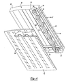
- FIG 4 shows an interior view of one trailing edge box 32.
- An afterburner spraybar 34 is housed within the trailing edge box 32 and provides fuel to mix with the leftover oxygen for a second combustion.
- the afterburner spraybar 34 extends radially within the afterburner 30 between the inner case 35 and the outer case 37.
- the afterburner spraybar 34 includes support lines 38 extending the length of the trailing edge box 32.
- a fuel conduit 18 is supported on the support lines 38.
- a plurality of diffusers 36 are spaced on the support lines 38. The diffusers 36 emit fuel, supplied by the fuel conduit 18, to mix with air for combustion.
- Supports 52 are also disposed along the length of the support lines 38. The supports 52 mate with the trailing edge box 32 to support and guide the afterburner spraybar 34.
- Cooling holes 58 are located on a first wall 42 and a second wall 44 of the trailing edge box 32 to allow oxygen to enter the trailing edge box 32.
- the exhaust from the second combustion leaves the trailing edge box 32 through exhaust holes 54 on a trailing edge side 43 of the trailing edge box 32. Exhaust flow is depicted by arrow F.
- the second combustion provides additional thrust to the turbine engine 10. Exhaust from the first and second combustion exits the turbine engine 10 through the exhaust nozzle 26 (shown in Figure 1 ).
- the example trailing edge box 32 is formed of sheet metal.
- the sheet metal is formed to create corrugations 40 on the internal side of the first wall 42 and the second wall 44 of the trailing edge box 32.
- the first wall 42 and the second wall 44 are opposing sides of the trailing edge box 32.
- the corrugations 40 may be formed as one piece with the first wall 42 and the second wall 44 or may be separate pieces of sheet metal which are attached to the first wall 42 and the second wall 44.
- the afterburner spraybar 34 is supported and guided by the corrugations 40 near the trailing edge side 43 of the trailing edge box 32. Although there is only one afterburner spraybar 34 in each trailing edge box other corrugations 40 within the trailing edge box provide structural support.
- Figure 5 shows a cross-section through the trailing edge box 32 looking from the outer case 35 toward the inner case 37 (shown in Figure 2 ). Air flows through the trailing edge box 32 to exit from the trailing edge side 43, depicted by arrow F.
- the corrugations 40 are shaped and sized to hold the supports 52 attached to the support lines 38 of the afterburner spraybar 34.
- the supports 52 are shaped to mate to the corrugations 40.
- the corrugations 40 are sized large enough to house the afterburner spraybar 34 but small enough to prevent shifting of the afterburner spraybar 34 during engine 10 operation.
- the shape of the corrugations 40 may vary to reflect the shape of the afterburner spraybar 34.
- the example supports 52 have a generally square shape.
- the corrugations 40 have U-shaped cross-section with the internal side of the first wall 42 and the second wall 44 crossing the opening of the U-shape.
- the U-shape of the corrugations 40 includes generally straight sides 46 extending from the first wall 42 or the second wall 44 of the trailing edge box 32.
- the sides 46 extend at an angle that corresponds to an angle of the support 52. Load on the trailing edge box 32 forces the first wall 42 and the second wall 44 away from each other, as a result the angle of the sides 46 places pressure on the supports 52 of the afterburner spraybar 34.
- the interference fit prevents shifting of the afterburner spraybar 34.
- the corrugation 40 has rounded corners 56 that substantially prevents formation of high stress areas.
- the corrugations 40 are sized and shaped to support the afterburner spraybar 34 and prevent shifting caused by vibrations during engine 10.
- the corrugations 40 also align the afterburner spraybar 34 within the trailing edge box 32.
- the corrugations 40 strengthen the walls of the trailing edge box 32.
- the example corrugations are located in the trailing edge box 32 within the afterburner 30 to support the afterburner spraybar 34.
- the example corrugations 40 provide support and alignment for the afterburner spraybar 34 within the trailing edge box 32, the corrugations 40 could be sized and shaped to provide support for other tubing or components as required.
Landscapes
- Engineering & Computer Science (AREA)
- Chemical & Material Sciences (AREA)
- Combustion & Propulsion (AREA)
- Mechanical Engineering (AREA)
- General Engineering & Computer Science (AREA)
- Exhaust Gas After Treatment (AREA)
- Heat-Exchange Devices With Radiators And Conduit Assemblies (AREA)
Description
- The invention generally relates to an arrangement to guide and support a fuel conduit within a turbine engine. More particularly, this invention relates to a structural support for spraybars within a trailing edge box.
- Turbine engines may have afterburners, or augmenters, located at the rear of the engine before an exhaust nozzle. Afterburners utilize unused oxygen from the turbine engine to obtain a second combustion. The second combustion provides additional thrust for the turbine engine. An afterburner includes trailing edge boxes that house fuel spraybars. The fuel spraybars are located in the trailing edge boxes to spray fuel where it can mix with unused oxygen.
- Turbine engines and afterburners are subject to heavy vibrations, which may cause high wear on the engine and afterburner components. The hostile environment requires support for the fuel spraybars and other components. Typically, the trailing edge boxes are formed from a metal casting to provide a surface for supporting the spraybar. In order to provide the required support and structure the metal casting has thick walls which result in a heavy component. The fuel spraybars and related tubing are mounted adjacent to each trailing edge box for support. The fuel spraybars and tubing are usually attached to the trailing edge boxes with brackets for support and guidance, and to limit the motion of the fuel spraybars and tubing during operation.
- A lighter arrangement to guide and support spraybars in a turbine engine is desirable.
- A turbine engine afterburner having the features of the preamble of claim 1 is disclosed in
EP-A-1229290 . - An afterburner for a turbine engine in accordance with the invention is set forth in claim 1.
- In a disclosed embodiment, the afterburner has multiple trailing edge boxes to house afterburner components. Each trailing edge box includes a spraybar providing fuel to mix with leftover oxygen for a second combustion.
- Each trailing edge box is formed of sheet metal having corrugations formed in the walls. The spraybar includes features that mate to the corrugated inner walls of the trailing edge box. The mating configuration between the spraybar and the corrugations hold the spraybar to prevent shifting during engine operation. The corrugations not only support and guide the spraybar, but also reinforce the walls of the trailing edge box.
- Accordingly, the disclosed trailing edge box supports and guides the spraybars while providing a lighter more rigid assembly.
- These and other features of the present invention can be best understood from the following specification and drawings, the following of which is a brief description.
-
-
Figure 1 is a schematic view of a turbine engine with an afterburner; -
Figure 2 is an end view of the afterburner showing trailing edge boxes according to this invention; -
Figure 3 is a cross-section of the afterburner showing the trailing edge boxes; -
Figure 4 is an interior view of a trailing edge box of the present invention;
and -
Figure 5 is a cross-sectional view of an example trailing edge box of the present invention. -
Figure 1 is a schematic view of aturbine engine 10. Air is pulled into theturbine engine 10 by afan 12 and flows through alow pressure compressor 14 and ahigh pressure compressor 16. Fuel is mixed with the oxygen and combustion occurs within thecombustor 20. Exhaust from combustion flows through ahigh pressure turbine 22 and alow pressure turbine 24 prior to leaving the engine through theexhaust nozzle 26. Theexample engine 10 includes an afterburner, or augmenter, 30. Aturbine exhaust case 28 is located in front of theexhaust nozzle 26 and behind thelow pressure turbine 24 to house theafterburner 30. - Referring to
Figures 2 and3 , an end view of theafterburner 30 looking forward in theengine 10 and a cross-section of theafterburner 30 are shown. An afterburnertrailing edge 31 is located at the aft end of theafterburner 30 and anafterburner leading edge 33 is located at the forward edge of theafterburner 30. Air flows, depicted by arrow F, into theafterburner 30 at the leadingedge 33 and exits at thetrailing edge 31. Theafterburner 30 includesvanes 50 positioned between anouter case 35 and aninner case 37 to support theinner case 37. Theafterburner 30 has trailingedge boxes 32 that house afterburner components. Thetrailing edge boxes 32 are positioned between theouter case 35 and aninner case 37 similar to thevanes 50. The trailing edge boxes are radially spaced about theinner case 37. Thetrailing edge boxes 32 are symmetrically disposed about an axis A of the engine and about theouter case 35 and interposed with thevanes 50. -
Figure 4 shows an interior view of onetrailing edge box 32. Anafterburner spraybar 34 is housed within thetrailing edge box 32 and provides fuel to mix with the leftover oxygen for a second combustion. Theafterburner spraybar 34 extends radially within theafterburner 30 between theinner case 35 and theouter case 37. Theafterburner spraybar 34 includessupport lines 38 extending the length of thetrailing edge box 32. Afuel conduit 18 is supported on thesupport lines 38. A plurality ofdiffusers 36 are spaced on thesupport lines 38. Thediffusers 36 emit fuel, supplied by thefuel conduit 18, to mix with air for combustion.Supports 52 are also disposed along the length of thesupport lines 38. The supports 52 mate with thetrailing edge box 32 to support and guide theafterburner spraybar 34. -
Cooling holes 58 are located on afirst wall 42 and asecond wall 44 of thetrailing edge box 32 to allow oxygen to enter thetrailing edge box 32. The exhaust from the second combustion leaves thetrailing edge box 32 throughexhaust holes 54 on atrailing edge side 43 of thetrailing edge box 32. Exhaust flow is depicted by arrow F. The second combustion provides additional thrust to theturbine engine 10. Exhaust from the first and second combustion exits theturbine engine 10 through the exhaust nozzle 26 (shown inFigure 1 ). - The example trailing
edge box 32 is formed of sheet metal. The sheet metal is formed to createcorrugations 40 on the internal side of thefirst wall 42 and thesecond wall 44 of thetrailing edge box 32. Thefirst wall 42 and thesecond wall 44 are opposing sides of thetrailing edge box 32. When thetrailing edge box 32 is assembled the corrugations from each side face one another running laterally from anouter case edge 39 toward an inner case edge 41. Thecorrugations 40 may be formed as one piece with thefirst wall 42 and thesecond wall 44 or may be separate pieces of sheet metal which are attached to thefirst wall 42 and thesecond wall 44. Theafterburner spraybar 34 is supported and guided by thecorrugations 40 near the trailingedge side 43 of the trailingedge box 32. Although there is only oneafterburner spraybar 34 in each trailing edge boxother corrugations 40 within the trailing edge box provide structural support. -
Figure 5 shows a cross-section through the trailingedge box 32 looking from theouter case 35 toward the inner case 37 (shown inFigure 2 ). Air flows through the trailingedge box 32 to exit from the trailingedge side 43, depicted by arrow F. Thecorrugations 40 are shaped and sized to hold thesupports 52 attached to the support lines 38 of theafterburner spraybar 34. The supports 52 are shaped to mate to thecorrugations 40. Thecorrugations 40 are sized large enough to house theafterburner spraybar 34 but small enough to prevent shifting of theafterburner spraybar 34 duringengine 10 operation. The shape of thecorrugations 40 may vary to reflect the shape of theafterburner spraybar 34. - The example supports 52 have a generally square shape. The
corrugations 40 have U-shaped cross-section with the internal side of thefirst wall 42 and thesecond wall 44 crossing the opening of the U-shape. The U-shape of thecorrugations 40 includes generally straight sides 46 extending from thefirst wall 42 or thesecond wall 44 of the trailingedge box 32. Thesides 46 extend at an angle that corresponds to an angle of thesupport 52. Load on the trailingedge box 32 forces thefirst wall 42 and thesecond wall 44 away from each other, as a result the angle of thesides 46 places pressure on thesupports 52 of theafterburner spraybar 34. The interference fit prevents shifting of theafterburner spraybar 34. Thecorrugation 40 has roundedcorners 56 that substantially prevents formation of high stress areas. - The
corrugations 40 are sized and shaped to support the afterburner spraybar 34 and prevent shifting caused by vibrations duringengine 10. Thecorrugations 40 also align theafterburner spraybar 34 within the trailingedge box 32. In addition, thecorrugations 40 strengthen the walls of the trailingedge box 32. - The example corrugations are located in the trailing
edge box 32 within theafterburner 30 to support theafterburner spraybar 34. Although the example corrugations 40 provide support and alignment for theafterburner spraybar 34 within the trailingedge box 32, thecorrugations 40 could be sized and shaped to provide support for other tubing or components as required. - Although a preferred embodiment of this invention has been disclosed, a worker of ordinary skill in this art would recognize that certain modifications would come within the scope of this invention. For that reason, the following claims should be studied to determine the true scope and content of this invention.
Claims (2)
- A turbine engine afterburner (30) comprising:a housing (32; 28) including corrugations (40; 64) having a U-shaped cross section to support and align a supply component (34; 66); anda supply (34; 66) component mounted on said corrugations (40; 64); whereinsaid housing comprises a trailing edge box (32) and said supply component comprises a spraybar (34) and support lines (38) of the spray bar (34); and characterized in that:said corrugations (40;64) have generally straight sides (46) connected by a connecting wall, said sides (46) extending at an angle to said connecting wall, said corrugations (40) being mounted on opposing walls (42,44) defining inner surfaces of said housing (32), said walls (42,44) crossing the opening of the U-shape, said corrugations (40) having rounded corners that substantially prevent formation of high stress areas, and being strengthening members of said housing (32); and in that:supports (52) on said supply component (34) mate with said corrugations (40) to retain said supply component (34) within said housing (32) and have a generally square shape with an angle that corresponds to the angle at which the side walls extend to said connecting wall, so that under load that forces the first and the second walls away from each other, the angle of the sides (46) places pressure on the support of the supply component, such that said sides (46) retain said supply component (34;66) with an interference fit.
- The turbine engine afterburner of claim 1, wherein said trailing edge box (32) is formed of sheet metal.
Applications Claiming Priority (1)
| Application Number | Priority Date | Filing Date | Title |
|---|---|---|---|
| US11/376,634 US7856827B2 (en) | 2006-03-14 | 2006-03-14 | Structural track support of spraybars/tubing |
Publications (3)
| Publication Number | Publication Date |
|---|---|
| EP1835230A2 EP1835230A2 (en) | 2007-09-19 |
| EP1835230A3 EP1835230A3 (en) | 2010-12-29 |
| EP1835230B1 true EP1835230B1 (en) | 2013-07-17 |
Family
ID=38080888
Family Applications (1)
| Application Number | Title | Priority Date | Filing Date |
|---|---|---|---|
| EP07250967.2A Expired - Fee Related EP1835230B1 (en) | 2006-03-14 | 2007-03-08 | Supporting structure for spray bars |
Country Status (3)
| Country | Link |
|---|---|
| US (1) | US7856827B2 (en) |
| EP (1) | EP1835230B1 (en) |
| JP (1) | JP2007248043A (en) |
Families Citing this family (2)
| Publication number | Priority date | Publication date | Assignee | Title |
|---|---|---|---|---|
| US9140213B2 (en) | 2011-12-06 | 2015-09-22 | United Technologies Corporation | Leaf spring damper for a turbine engine fuel delivery system |
| US20160076450A1 (en) * | 2014-04-21 | 2016-03-17 | Bob Burkett | Solar Jet Turbofan Aircraft Engine |
Citations (1)
| Publication number | Priority date | Publication date | Assignee | Title |
|---|---|---|---|---|
| US20060032231A1 (en) * | 2004-08-12 | 2006-02-16 | Volvo Aero Corporation | Method and apparatus for providing an afterburner fuel-feed arrangement |
Family Cites Families (17)
| Publication number | Priority date | Publication date | Assignee | Title |
|---|---|---|---|---|
| NL271986A (en) * | 1961-11-30 | |||
| US3750402A (en) * | 1963-08-07 | 1973-08-07 | Gen Electric | Mixed flow augmentation system |
| US3747345A (en) * | 1972-07-24 | 1973-07-24 | United Aircraft Corp | Shortened afterburner construction for turbine engine |
| FR2594998B1 (en) * | 1986-02-24 | 1988-06-10 | Fragema Framatome & Cogema | GRILLE FOR NUCLEAR FUEL ASSEMBLY, AND ASSEMBLY COMPRISING APPLICATION |
| FR2678714B1 (en) * | 1991-07-03 | 1993-09-17 | Snecma | REDUCED POLLUTION STATOREACTOR FIREPLACE. |
| US5259009A (en) * | 1991-08-19 | 1993-11-02 | Siemens Power Corporation | Boiling water reactor fuel rod assembly with fuel rod spacer arrangement |
| FR2689567B1 (en) * | 1992-04-01 | 1994-05-27 | Snecma | FUEL INJECTOR FOR A POST-COMBUSTION CHAMBER OF A TURBOMACHINE. |
| US5385015A (en) * | 1993-07-02 | 1995-01-31 | United Technologies Corporation | Augmentor burner |
| FR2709342B1 (en) * | 1993-08-25 | 1995-09-22 | Snecma | Post combustion device of a turbojet engine. |
| US5396763A (en) * | 1994-04-25 | 1995-03-14 | General Electric Company | Cooled spraybar and flameholder assembly including a perforated hollow inner air baffle for impingement cooling an outer heat shield |
| US5685140A (en) * | 1995-06-21 | 1997-11-11 | United Technologies Corporation | Method for distributing fuel within an augmentor |
| GB9623615D0 (en) * | 1996-11-13 | 1997-07-09 | Rolls Royce Plc | Jet pipe liner |
| US5813221A (en) * | 1997-01-14 | 1998-09-29 | General Electric Company | Augmenter with integrated fueling and cooling |
| US6038852A (en) * | 1997-12-05 | 2000-03-21 | United Technologies Corporation | Wear resistant augmentor fuel manifold clamp |
| US6463739B1 (en) | 2001-02-05 | 2002-10-15 | General Electric Company | Afterburner heat shield |
| FR2873411B1 (en) * | 2004-07-21 | 2009-08-21 | Snecma Moteurs Sa | TURBOREACTOR WITH PROTECTIVE MEANS FOR A FUEL INJECTION DEVICE, INJECTION DEVICE AND PROTECTIVE COVER FOR THE TURBOJET ENGINE |
| US7647775B2 (en) * | 2005-06-30 | 2010-01-19 | United Technologies Corporation | Augmentor spray bars |
-
2006
- 2006-03-14 US US11/376,634 patent/US7856827B2/en not_active Expired - Fee Related
-
2007
- 2007-03-08 EP EP07250967.2A patent/EP1835230B1/en not_active Expired - Fee Related
- 2007-03-14 JP JP2007064608A patent/JP2007248043A/en active Pending
Patent Citations (1)
| Publication number | Priority date | Publication date | Assignee | Title |
|---|---|---|---|---|
| US20060032231A1 (en) * | 2004-08-12 | 2006-02-16 | Volvo Aero Corporation | Method and apparatus for providing an afterburner fuel-feed arrangement |
Also Published As
| Publication number | Publication date |
|---|---|
| US7856827B2 (en) | 2010-12-28 |
| US20070214793A1 (en) | 2007-09-20 |
| EP1835230A3 (en) | 2010-12-29 |
| EP1835230A2 (en) | 2007-09-19 |
| JP2007248043A (en) | 2007-09-27 |
Similar Documents
| Publication | Publication Date | Title |
|---|---|---|
| US8186942B2 (en) | Nacelle assembly with turbulators | |
| EP1793165A2 (en) | Liquid fuel nozzle, gas turbine combustor, and method of rebuilding gas turbine combustor | |
| US8875517B2 (en) | Diffuser for turbine engine including indented annular webs | |
| EP3460331B1 (en) | Canted combustor for gas turbine engine | |
| EP2514947A1 (en) | Gas turbine engine including a nacelle assembly which comprises a cavity and a fan containment case | |
| US10197279B2 (en) | Combustor assembly for a turbine engine | |
| US7430852B2 (en) | Turbojet having a large bypass ratio | |
| CN101778765B (en) | Coupling system connecting an internal structure and an external structure of a jet engine nacelle | |
| EP1338784B1 (en) | Lobe mixer for jet flow | |
| EP2980393B1 (en) | Gas turbine engine | |
| EP1835230A2 (en) | Supporting structure for spray bars | |
| US10655502B2 (en) | Stator assembly with retention clip for gas turbine engine | |
| US9488106B2 (en) | Assembly formed by a turbine engine and a system for attaching it to an aircraft structure | |
| US20100024425A1 (en) | Turbine engine fuel nozzle | |
| US9127552B2 (en) | Transition piece aft frame with fuel injection apertures | |
| EP1840468A2 (en) | Structural metering plate | |
| US20200149402A1 (en) | Airfoil with convex sides and multi-piece baffle | |
| EP2397654B1 (en) | Vane assembly and method for assembling the same | |
| JP4031774B2 (en) | Gas turbine combustor | |
| US9863324B2 (en) | Oil tank mount with stiffeners | |
| EP3121430B1 (en) | A nacelle assembly | |
| JP4495198B2 (en) | Gas turbine combustor | |
| US12326112B2 (en) | Gas turbine engine bypass louver and baffle rib design | |
| EP1662203B1 (en) | Combustor | |
| EP2943654B1 (en) | Liner assembly for a gas turbine engine |
Legal Events
| Date | Code | Title | Description |
|---|---|---|---|
| PUAI | Public reference made under article 153(3) epc to a published international application that has entered the european phase |
Free format text: ORIGINAL CODE: 0009012 |
|
| AK | Designated contracting states |
Kind code of ref document: A2 Designated state(s): AT BE BG CH CY CZ DE DK EE ES FI FR GB GR HU IE IS IT LI LT LU LV MC MT NL PL PT RO SE SI SK TR |
|
| AX | Request for extension of the european patent |
Extension state: AL BA HR MK YU |
|
| PUAL | Search report despatched |
Free format text: ORIGINAL CODE: 0009013 |
|
| AK | Designated contracting states |
Kind code of ref document: A3 Designated state(s): AT BE BG CH CY CZ DE DK EE ES FI FR GB GR HU IE IS IT LI LT LU LV MC MT NL PL PT RO SE SI SK TR |
|
| AX | Request for extension of the european patent |
Extension state: AL BA HR MK RS |
|
| RIC1 | Information provided on ipc code assigned before grant |
Ipc: F02K 3/10 20060101ALI20101122BHEP Ipc: F23R 3/60 20060101ALI20101122BHEP Ipc: F23R 3/20 20060101AFI20070607BHEP |
|
| 17P | Request for examination filed |
Effective date: 20110629 |
|
| AKX | Designation fees paid |
Designated state(s): DE GB |
|
| 17Q | First examination report despatched |
Effective date: 20120530 |
|
| GRAP | Despatch of communication of intention to grant a patent |
Free format text: ORIGINAL CODE: EPIDOSNIGR1 |
|
| GRAS | Grant fee paid |
Free format text: ORIGINAL CODE: EPIDOSNIGR3 |
|
| GRAA | (expected) grant |
Free format text: ORIGINAL CODE: 0009210 |
|
| AK | Designated contracting states |
Kind code of ref document: B1 Designated state(s): DE GB |
|
| REG | Reference to a national code |
Ref country code: GB Ref legal event code: FG4D |
|
| REG | Reference to a national code |
Ref country code: DE Ref legal event code: R096 Ref document number: 602007031661 Country of ref document: DE Effective date: 20130912 |
|
| PLBE | No opposition filed within time limit |
Free format text: ORIGINAL CODE: 0009261 |
|
| STAA | Information on the status of an ep patent application or granted ep patent |
Free format text: STATUS: NO OPPOSITION FILED WITHIN TIME LIMIT |
|
| 26N | No opposition filed |
Effective date: 20140422 |
|
| REG | Reference to a national code |
Ref country code: DE Ref legal event code: R097 Ref document number: 602007031661 Country of ref document: DE Effective date: 20140422 |
|
| REG | Reference to a national code |
Ref country code: DE Ref legal event code: R119 Ref document number: 602007031661 Country of ref document: DE |
|
| GBPC | Gb: european patent ceased through non-payment of renewal fee |
Effective date: 20140308 |
|
| REG | Reference to a national code |
Ref country code: DE Ref legal event code: R119 Ref document number: 602007031661 Country of ref document: DE Effective date: 20141001 |
|
| PG25 | Lapsed in a contracting state [announced via postgrant information from national office to epo] |
Ref country code: DE Free format text: LAPSE BECAUSE OF NON-PAYMENT OF DUE FEES Effective date: 20141001 Ref country code: GB Free format text: LAPSE BECAUSE OF NON-PAYMENT OF DUE FEES Effective date: 20140308 |