EP1834845A2 - Vehicle steering wheel with an integrated airbag - Google Patents
Vehicle steering wheel with an integrated airbag Download PDFInfo
- Publication number
- EP1834845A2 EP1834845A2 EP07381018A EP07381018A EP1834845A2 EP 1834845 A2 EP1834845 A2 EP 1834845A2 EP 07381018 A EP07381018 A EP 07381018A EP 07381018 A EP07381018 A EP 07381018A EP 1834845 A2 EP1834845 A2 EP 1834845A2
- Authority
- EP
- European Patent Office
- Prior art keywords
- steering wheel
- snap
- airbag module
- fitting
- spring
- Prior art date
- Legal status (The legal status is an assumption and is not a legal conclusion. Google has not performed a legal analysis and makes no representation as to the accuracy of the status listed.)
- Granted
Links
Images

Classifications
-
- B—PERFORMING OPERATIONS; TRANSPORTING
- B60—VEHICLES IN GENERAL
- B60R—VEHICLES, VEHICLE FITTINGS, OR VEHICLE PARTS, NOT OTHERWISE PROVIDED FOR
- B60R21/00—Arrangements or fittings on vehicles for protecting or preventing injuries to occupants or pedestrians in case of accidents or other traffic risks
- B60R21/02—Occupant safety arrangements or fittings, e.g. crash pads
- B60R21/16—Inflatable occupant restraints or confinements designed to inflate upon impact or impending impact, e.g. air bags
- B60R21/20—Arrangements for storing inflatable members in their non-use or deflated condition; Arrangement or mounting of air bag modules or components
- B60R21/203—Arrangements for storing inflatable members in their non-use or deflated condition; Arrangement or mounting of air bag modules or components in steering wheels or steering columns
- B60R21/2035—Arrangements for storing inflatable members in their non-use or deflated condition; Arrangement or mounting of air bag modules or components in steering wheels or steering columns using modules containing inflator, bag and cover attachable to the steering wheel as a complete sub-unit
Definitions
- the present invention relates to an automotive vehicle steering wheel with an integrated airbag module and more particularly to the steering wheel of an automotive vehicle with an airbag module snap-fitted in the steering wheel.
- Spanish utility model 1 040 263 of the same applicant of the present invention describes means for snap-fitting the airbag module to the steering wheel consisting on one hand of a spring having one or more points fixed in the casing of the airbag module and on the other hand an insert of the steering wheel which is formed from a body finished in an arrow tip to allow the easy introduction thereof in a receptacle closing said spring and keeping it retained by the horizontal section of the mentioned insert.
- the steering wheel includes an access from outside by which, by means of a screwdriver or the like, the resistance of the spring can be overcome and the unblocking of the snap-fitting and therefore the removal of the insert from the receptacle in which it is retained by the spring is allowed.
- European patent EP 1 179 457 describes means for snap-fitting the airbag module to the steering wheel consisting on one hand of feet integral with the steering wheel and on the other hand of an elastic rod arranged in the casing of the airbag module. Said elastic rod is deformed by means of a suitable tool in order to remove the snap-fitting of the airbag module.
- a drawback of the previous technique is that the snap-fitting removal operation is not easy because the immediate contact of the snap-fitting removing tool with the snap-fitting spring is not ensured which means that several attempts may be necessary until it is achieved.
- the present invention is oriented to solving this drawback.
- the steering wheel of an automotive vehicle with an integrated airbag module according to the present invention comprises:
- said channel not only serves as a duct for the passage of a snap-fitting removing tool but also as a guide thereof, which considerably facilitates the snap-fitting removal operation.
- the figures show a steering wheel 11 of an automotive vehicle which is configured, as is well known in the art, with a base 12, a ring 13 and several radii 15 and is structured based on a framework 17 and a foam filling 19.
- the steering wheel 11 has an airbag module 21 fixed thereto.
- the fixing of the airbag module 21 to the steering wheel 11 is carried out by means of snap-fitting two snap-fitting parts 32 of a spring 31 located in the lower part of the airbag module 21 in the hooks 39 of two arms 33 incorporated in the framework 17 of the steering wheel 11.
- This snap-fitting is carried out vertically because the spring 31 is elastic.
- said snap-fitting parts 32 of the spring 31 are U-shaped.
- Said arms 33 are incorporated in the framework 17 of the steering wheel 11 in the areas occupied by the two diametrically opposite radii 15 and therein there is distinguished a first part 35 integrated in the structure of the steering wheel 11 and a second part 37 projecting from said structure.
- the arms 33 include a channel 41 in the lower part thereof which serves as a duct for the passage of a tool 45 for removing the snap-fitting of the airbag module 21 by pushing the snap-fitting parts 32 of said spring 31.
- the inlet opening 43 of this channel 41 is in the lower part of the radius 15 of the steering wheel 11.
- the rear cover 51 of the steering wheel includes in turn ribs 53 finished in line with the channel 41 to facilitate the guiding of the tool 45 during the snap-fitting removal operation.
Landscapes
- Engineering & Computer Science (AREA)
- Mechanical Engineering (AREA)
- Air Bags (AREA)
- Steering Controls (AREA)
Abstract
Description
- The present invention relates to an automotive vehicle steering wheel with an integrated airbag module and more particularly to the steering wheel of an automotive vehicle with an airbag module snap-fitted in the steering wheel.
-
Spanish utility model 1 040 263 -
European patent EP 1 179 457 - A drawback of the previous technique is that the snap-fitting removal operation is not easy because the immediate contact of the snap-fitting removing tool with the snap-fitting spring is not ensured which means that several attempts may be necessary until it is achieved.
- The present invention is oriented to solving this drawback.
- The steering wheel of an automotive vehicle with an integrated airbag module according to the present invention comprises:
- A steering wheel with a base, a ring and several radii structured by a framework and a foam filling.
- An airbag module
- Cooperating means for fixing the airbag module in the steering wheel, consisting of:
- a) In the steering wheel, at least two arms with a hook at the end thereof, incorporated in the framework of the steering wheel in the area of one of its radii.
- b) In the airbag module, a spring arranged in the lower part thereof with two areas provided for being snap-fit to said hooks by vertical pushing.
- An open channel in the lower part of said arms to allow the passage of a tool that can remove the snap-fitting of the airbag module by pushing said springs.
- An important feature of the present invention is that said channel not only serves as a duct for the passage of a snap-fitting removing tool but also as a guide thereof, which considerably facilitates the snap-fitting removal operation.
- Other features and advantages of the present invention will be disclosed in the following description of an illustrative and in no case limiting embodiment of the object thereof in relation to the attached drawings.
-
- Figure 1 is a front view of a vehicle steering wheel according to the present invention.
- Figure 2 is a side view of a vehicle steering wheel according to the present invention.
- Figure 3 is a rear view of a vehicle steering wheel according to the present invention.
- Figure 4 is a sectional view of an arm incorporated in the vehicle steering wheel according to the present invention to serve as a means for fixing the airbag module.
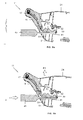
- Figures 5a and 5b are cross-sectional views of a vehicle steering wheel with an integrated airbag module according to the present invention which illustrates the snap-fitting removal operation.
- The figures show a
steering wheel 11 of an automotive vehicle which is configured, as is well known in the art, with abase 12, aring 13 andseveral radii 15 and is structured based on aframework 17 and afoam filling 19. Thesteering wheel 11 has anairbag module 21 fixed thereto. - The fixing of the
airbag module 21 to thesteering wheel 11 is carried out by means of snap-fitting two snap-fitting parts 32 of aspring 31 located in the lower part of theairbag module 21 in thehooks 39 of twoarms 33 incorporated in theframework 17 of thesteering wheel 11. This snap-fitting is carried out vertically because thespring 31 is elastic. In a preferred embodiment said snap-fittingparts 32 of thespring 31 are U-shaped. - Said
arms 33 are incorporated in theframework 17 of thesteering wheel 11 in the areas occupied by the two diametricallyopposite radii 15 and therein there is distinguished afirst part 35 integrated in the structure of thesteering wheel 11 and asecond part 37 projecting from said structure. - In turn, the
arms 33 include achannel 41 in the lower part thereof which serves as a duct for the passage of atool 45 for removing the snap-fitting of theairbag module 21 by pushing the snap-fittingparts 32 of saidspring 31. The inlet opening 43 of thischannel 41 is in the lower part of theradius 15 of thesteering wheel 11. Therear cover 51 of the steering wheel includes inturn ribs 53 finished in line with thechannel 41 to facilitate the guiding of thetool 45 during the snap-fitting removal operation. - In this operation, the force F1 necessary to separate the
spring 31 from thehook 39 is applied to thetool 45 in the direction of thechannel 41 and at the same time the vertical force F2 necessary to release theairbag module 21 is applied. - Although several embodiments of the invention have been described and shown, it is evident that modifications comprised within the scope thereof can be introduced therein, and the latter must not be considered limited to said embodiments but to the contents of the following claims.
Claims (4)
- A steering wheel (11) of an automotive vehicle with an integrated airbag module (21), the steering wheel comprising a base (12), ring (13) and several radii (15) structured based on a framework (17) and a foam filling (19); the airbag module (21) and the steering wheel (11) comprising cooperating means for fixing the airbag module (21) in the steering wheel (11), characterized in that:a) in the steering wheel (11), said means consist of at least two arms (33) with a hook (39) at the end thereof, incorporated in the framework (17) of the steering wheel (11) in the area of one of its radii (15);b) in the airbag (21), said means consist of a spring (31) arranged in the lower part thereof which is snap-fit to said hooks (39) by vertical pushing in two snap-fitting parts (32) configured for that purpose;c) said arms (33) include an open channel (41) in the lower part thereof to allow the passage of a tool (45) that can remove the snap-fitting of the airbag module (21) by pushing said snap-fitting parts (32) of the spring (31).
- A steering wheel (11) of an automotive vehicle with an integrated airbag module (21) according to claim 1, characterized in that a first part (35) of said arms (33) is integrated in the structure of the steering wheel (11) and a second part (37) projects from said structure.
- A steering wheel (11) of an automotive vehicle with an integrated airbag module (21) according to claim 1, characterized in that the inlet opening (43) of each channel (41) is located in the lower part of a radius (15) of the steering wheel (11).
- A steering wheel (11) of an automotive vehicle with an integrated airbag module (21) according to claim 1, characterized in that said snap-fitting parts (32) of the spring (31) are U-shaped.
Applications Claiming Priority (1)
| Application Number | Priority Date | Filing Date | Title |
|---|---|---|---|
| ES200600639A ES2301341B1 (en) | 2006-03-13 | 2006-03-13 | CAR WHEEL WITH INTEGRATED AIRBAG. |
Publications (3)
| Publication Number | Publication Date |
|---|---|
| EP1834845A2 true EP1834845A2 (en) | 2007-09-19 |
| EP1834845A3 EP1834845A3 (en) | 2008-12-03 |
| EP1834845B1 EP1834845B1 (en) | 2010-12-01 |
Family
ID=38134969
Family Applications (1)
| Application Number | Title | Priority Date | Filing Date |
|---|---|---|---|
| EP07381018A Not-in-force EP1834845B1 (en) | 2006-03-13 | 2007-03-01 | Vehicle steering wheel with an integrated airbag |
Country Status (7)
| Country | Link |
|---|---|
| US (1) | US7628420B2 (en) |
| EP (1) | EP1834845B1 (en) |
| JP (1) | JP2007246081A (en) |
| CN (1) | CN101037103B (en) |
| AT (1) | ATE490127T1 (en) |
| DE (1) | DE602007010855D1 (en) |
| ES (1) | ES2301341B1 (en) |
Cited By (1)
| Publication number | Priority date | Publication date | Assignee | Title |
|---|---|---|---|---|
| US20220314919A1 (en) * | 2019-07-04 | 2022-10-06 | Autoliv Development Ab | Device for removably mounting an airbag module on a steering wheel |
Families Citing this family (6)
| Publication number | Priority date | Publication date | Assignee | Title |
|---|---|---|---|---|
| KR100969098B1 (en) | 2008-05-07 | 2010-07-09 | 현대자동차주식회사 | Steering wheel of vehicle |
| KR101637264B1 (en) * | 2010-09-29 | 2016-07-07 | 현대자동차 주식회사 | Air bag module extracting unit for steeling wheel |
| JP5669018B2 (en) * | 2011-04-22 | 2015-02-12 | いすゞ自動車株式会社 | Airbag device mounting structure |
| JP6136683B2 (en) * | 2013-07-16 | 2017-05-31 | タカタ株式会社 | Steering wheel with airbag device for driver's seat |
| DE202017105933U1 (en) * | 2017-09-28 | 2019-01-08 | Dalphi Metal Espana, S.A. | Steering wheel for a motor vehicle |
| FR3085914B1 (en) * | 2018-09-14 | 2020-08-14 | Autoliv Dev | REMOVABLE MOUNTING DEVICE FOR AN INFLATABLE CUSHION MODULE |
Citations (2)
| Publication number | Priority date | Publication date | Assignee | Title |
|---|---|---|---|---|
| ES1040263U (en) | 1998-05-22 | 1999-03-16 | Dalphi Metal Espana Sa | New clipaje módulo air-bag with the steering wheel. (Machine-translation by Google Translate, not legally binding) |
| EP1179457A1 (en) | 2000-08-02 | 2002-02-13 | Autoliv-Isodelta | Vehicle steering wheel element with snap-in system and steering wheel comprising it |
Family Cites Families (18)
| Publication number | Priority date | Publication date | Assignee | Title |
|---|---|---|---|---|
| US5087069A (en) * | 1990-12-20 | 1992-02-11 | General Motors Corporation | Restraint system mounting |
| US5738369A (en) * | 1996-10-09 | 1998-04-14 | Breed Automotive Technology, Inc. | Snap-on air bag and horn switch module |
| DE29621295U1 (en) * | 1996-11-27 | 1997-02-06 | Petri Ag, 63743 Aschaffenburg | Device for fastening an airbag module in the steering wheel |
| DE19725684C2 (en) * | 1997-06-18 | 2003-10-09 | Autoliv Dev | Steering wheel with an airbag module attached to it by means of a snap connection |
| DE29805207U1 (en) * | 1998-03-23 | 1998-06-04 | TRW Automotive Safety Systems GmbH, 63743 Aschaffenburg | Steering wheel with an airbag |
| DE19927032A1 (en) * | 1999-06-04 | 2000-12-14 | Petri Ag | Arrangement for locking an airbag module with a steering wheel |
| ES1045447Y (en) * | 1999-11-23 | 2001-03-01 | Dalphi Metal Espana Sa | QUICK FIXING PROVISION BETWEEN THE AIRBAG MODULE AND THE WHEEL. |
| CN2455545Y (en) * | 2000-10-24 | 2001-10-24 | 上海久久汽车安全装置有限公司 | Safety air bag for vehicle driver and assistant |
| US6830263B2 (en) * | 2002-02-08 | 2004-12-14 | Key Safety Systems, Inc. | Method for attaching an airbag module |
| GB2385834A (en) * | 2002-03-01 | 2003-09-03 | Autoliv Dev | Air bag mounting arrangement on vehicle steering wheel |
| DE20311760U1 (en) * | 2003-07-30 | 2003-12-11 | Trw Automotive Safety Systems Gmbh | vehicle steering wheel |
| US7159898B2 (en) * | 2004-04-20 | 2007-01-09 | General Motors Corporation | Vehicle air bag module retention system |
| EP1595754B1 (en) * | 2004-05-10 | 2008-06-04 | Key Safety Systems, Inc. | Assembly for retaining airbag modules to steering wheels |
| US7510209B2 (en) * | 2004-09-10 | 2009-03-31 | Delphi Technologies, Inc. | Airbag module with integral locking mechanism and method of making |
| JP4797584B2 (en) * | 2005-03-16 | 2011-10-19 | タカタ株式会社 | Steering wheel with airbag device |
| US7490852B2 (en) * | 2005-03-21 | 2009-02-17 | Delphi Technologies, Inc. | Apparatus and method for providing a horn contact mechanism |
| US7380817B2 (en) * | 2005-03-29 | 2008-06-03 | Key Safety Systems, Inc. | Assembly for retaining an airbag module to a steering wheel |
| ES2301339B1 (en) * | 2006-03-13 | 2009-05-01 | Dalphi Metal España S.A. | CAR FLYWHEEL WITH FLOATING CLAXON. |
-
2006
- 2006-03-13 ES ES200600639A patent/ES2301341B1/en not_active Withdrawn - After Issue
-
2007
- 2007-02-20 US US11/708,713 patent/US7628420B2/en active Active
- 2007-03-01 DE DE602007010855T patent/DE602007010855D1/en active Active
- 2007-03-01 AT AT07381018T patent/ATE490127T1/en not_active IP Right Cessation
- 2007-03-01 EP EP07381018A patent/EP1834845B1/en not_active Not-in-force
- 2007-03-09 CN CN2007100862215A patent/CN101037103B/en not_active Expired - Fee Related
- 2007-03-12 JP JP2007061927A patent/JP2007246081A/en active Pending
Patent Citations (2)
| Publication number | Priority date | Publication date | Assignee | Title |
|---|---|---|---|---|
| ES1040263U (en) | 1998-05-22 | 1999-03-16 | Dalphi Metal Espana Sa | New clipaje módulo air-bag with the steering wheel. (Machine-translation by Google Translate, not legally binding) |
| EP1179457A1 (en) | 2000-08-02 | 2002-02-13 | Autoliv-Isodelta | Vehicle steering wheel element with snap-in system and steering wheel comprising it |
Cited By (2)
| Publication number | Priority date | Publication date | Assignee | Title |
|---|---|---|---|---|
| US20220314919A1 (en) * | 2019-07-04 | 2022-10-06 | Autoliv Development Ab | Device for removably mounting an airbag module on a steering wheel |
| US11772591B2 (en) * | 2019-07-04 | 2023-10-03 | Autoliv Development Ab | Device for removably mounting an airbag module on a steering wheel |
Also Published As
| Publication number | Publication date |
|---|---|
| EP1834845B1 (en) | 2010-12-01 |
| CN101037103A (en) | 2007-09-19 |
| ATE490127T1 (en) | 2010-12-15 |
| ES2301341B1 (en) | 2009-05-01 |
| US7628420B2 (en) | 2009-12-08 |
| CN101037103B (en) | 2010-12-01 |
| EP1834845A3 (en) | 2008-12-03 |
| DE602007010855D1 (en) | 2011-01-13 |
| ES2301341A1 (en) | 2008-06-16 |
| US20070210563A1 (en) | 2007-09-13 |
| JP2007246081A (en) | 2007-09-27 |
Similar Documents
| Publication | Publication Date | Title |
|---|---|---|
| EP1834845B1 (en) | Vehicle steering wheel with an integrated airbag | |
| JP4440714B2 (en) | Container holding unit and cup holder device | |
| JP3600880B2 (en) | Vehicle roof rack fixing device | |
| EP2520466B1 (en) | Mounting structure for an automotive exterior member | |
| EP1350667A3 (en) | Industrial vehicle | |
| CN107995901A (en) | System for door module to be fastened to car door | |
| EP1393966A3 (en) | Child seat mounting structure | |
| CN104590075B (en) | Glass stand and the car door comprising glass stand | |
| EP3138394B1 (en) | Pet tag holder system | |
| US7963417B2 (en) | Tank filling region of a motor vehicle | |
| JP2011157054A (en) | Device for installation of a-pillar garnish | |
| EP1437293A3 (en) | Small vehicle | |
| CN108454531A (en) | fixture mounting base | |
| CN112368183B (en) | Trim elements for rear covers of motor vehicles, rear covers and motor vehicles | |
| JP6774713B2 (en) | Interior parts | |
| CN109664844A (en) | Vehicle harness fixing piece, mounting assembly and vehicle | |
| JP2014065406A (en) | Fitting structure of pull-handle | |
| CN201597641U (en) | motor vehicle | |
| CN207207883U (en) | A kind of loudspeaker cap fixing structure and steering wheel | |
| EP1245467A3 (en) | Nozzle for a vehicle windscreen washing device | |
| CN222522475U (en) | Auxiliary instrument panel structure and vehicle | |
| JP2011156949A (en) | Lining member for box | |
| JP2005007908A (en) | Door trim for automobile | |
| JP4442739B2 (en) | Tire stopper storage device | |
| FR2903957B1 (en) | DOOR LOWER REINFORCEMENT DEVICE |
Legal Events
| Date | Code | Title | Description |
|---|---|---|---|
| PUAI | Public reference made under article 153(3) epc to a published international application that has entered the european phase |
Free format text: ORIGINAL CODE: 0009012 |
|
| AK | Designated contracting states |
Kind code of ref document: A2 Designated state(s): AT BE BG CH CY CZ DE DK EE ES FI FR GB GR HU IE IS IT LI LT LU LV MC MT NL PL PT RO SE SI SK TR |
|
| AX | Request for extension of the european patent |
Extension state: AL BA HR MK YU |
|
| PUAL | Search report despatched |
Free format text: ORIGINAL CODE: 0009013 |
|
| AK | Designated contracting states |
Kind code of ref document: A3 Designated state(s): AT BE BG CH CY CZ DE DK EE ES FI FR GB GR HU IE IS IT LI LT LU LV MC MT NL PL PT RO SE SI SK TR |
|
| AX | Request for extension of the european patent |
Extension state: AL BA HR MK RS |
|
| 17P | Request for examination filed |
Effective date: 20090603 |
|
| AKX | Designation fees paid |
Designated state(s): AT BE BG CH CY CZ DE DK EE ES FI FR GB GR HU IE IS IT LI LT LU LV MC MT NL PL PT RO SE SI SK TR |
|
| GRAP | Despatch of communication of intention to grant a patent |
Free format text: ORIGINAL CODE: EPIDOSNIGR1 |
|
| GRAS | Grant fee paid |
Free format text: ORIGINAL CODE: EPIDOSNIGR3 |
|
| GRAA | (expected) grant |
Free format text: ORIGINAL CODE: 0009210 |
|
| AK | Designated contracting states |
Kind code of ref document: B1 Designated state(s): AT BE BG CH CY CZ DE DK EE ES FI FR GB GR HU IE IS IT LI LT LU LV MC MT NL PL PT RO SE SI SK TR |
|
| REG | Reference to a national code |
Ref country code: GB Ref legal event code: FG4D |
|
| REG | Reference to a national code |
Ref country code: CH Ref legal event code: EP |
|
| REG | Reference to a national code |
Ref country code: IE Ref legal event code: FG4D |
|
| REF | Corresponds to: |
Ref document number: 602007010855 Country of ref document: DE Date of ref document: 20110113 Kind code of ref document: P |
|
| REG | Reference to a national code |
Ref country code: NL Ref legal event code: VDEP Effective date: 20101201 |
|
| PG25 | Lapsed in a contracting state [announced via postgrant information from national office to epo] |
Ref country code: LT Free format text: LAPSE BECAUSE OF FAILURE TO SUBMIT A TRANSLATION OF THE DESCRIPTION OR TO PAY THE FEE WITHIN THE PRESCRIBED TIME-LIMIT Effective date: 20101201 |
|
| LTIE | Lt: invalidation of european patent or patent extension |
Effective date: 20101201 |
|
| PG25 | Lapsed in a contracting state [announced via postgrant information from national office to epo] |
Ref country code: LV Free format text: LAPSE BECAUSE OF FAILURE TO SUBMIT A TRANSLATION OF THE DESCRIPTION OR TO PAY THE FEE WITHIN THE PRESCRIBED TIME-LIMIT Effective date: 20101201 Ref country code: BG Free format text: LAPSE BECAUSE OF FAILURE TO SUBMIT A TRANSLATION OF THE DESCRIPTION OR TO PAY THE FEE WITHIN THE PRESCRIBED TIME-LIMIT Effective date: 20110301 Ref country code: CY Free format text: LAPSE BECAUSE OF FAILURE TO SUBMIT A TRANSLATION OF THE DESCRIPTION OR TO PAY THE FEE WITHIN THE PRESCRIBED TIME-LIMIT Effective date: 20101201 Ref country code: NL Free format text: LAPSE BECAUSE OF FAILURE TO SUBMIT A TRANSLATION OF THE DESCRIPTION OR TO PAY THE FEE WITHIN THE PRESCRIBED TIME-LIMIT Effective date: 20101201 Ref country code: AT Free format text: LAPSE BECAUSE OF FAILURE TO SUBMIT A TRANSLATION OF THE DESCRIPTION OR TO PAY THE FEE WITHIN THE PRESCRIBED TIME-LIMIT Effective date: 20101201 Ref country code: FI Free format text: LAPSE BECAUSE OF FAILURE TO SUBMIT A TRANSLATION OF THE DESCRIPTION OR TO PAY THE FEE WITHIN THE PRESCRIBED TIME-LIMIT Effective date: 20101201 Ref country code: SI Free format text: LAPSE BECAUSE OF FAILURE TO SUBMIT A TRANSLATION OF THE DESCRIPTION OR TO PAY THE FEE WITHIN THE PRESCRIBED TIME-LIMIT Effective date: 20101201 Ref country code: SE Free format text: LAPSE BECAUSE OF FAILURE TO SUBMIT A TRANSLATION OF THE DESCRIPTION OR TO PAY THE FEE WITHIN THE PRESCRIBED TIME-LIMIT Effective date: 20101201 |
|
| PG25 | Lapsed in a contracting state [announced via postgrant information from national office to epo] |
Ref country code: GR Free format text: LAPSE BECAUSE OF FAILURE TO SUBMIT A TRANSLATION OF THE DESCRIPTION OR TO PAY THE FEE WITHIN THE PRESCRIBED TIME-LIMIT Effective date: 20110302 |
|
| PG25 | Lapsed in a contracting state [announced via postgrant information from national office to epo] |
Ref country code: CZ Free format text: LAPSE BECAUSE OF FAILURE TO SUBMIT A TRANSLATION OF THE DESCRIPTION OR TO PAY THE FEE WITHIN THE PRESCRIBED TIME-LIMIT Effective date: 20101201 Ref country code: PT Free format text: LAPSE BECAUSE OF FAILURE TO SUBMIT A TRANSLATION OF THE DESCRIPTION OR TO PAY THE FEE WITHIN THE PRESCRIBED TIME-LIMIT Effective date: 20110401 Ref country code: ES Free format text: LAPSE BECAUSE OF FAILURE TO SUBMIT A TRANSLATION OF THE DESCRIPTION OR TO PAY THE FEE WITHIN THE PRESCRIBED TIME-LIMIT Effective date: 20110312 Ref country code: BE Free format text: LAPSE BECAUSE OF FAILURE TO SUBMIT A TRANSLATION OF THE DESCRIPTION OR TO PAY THE FEE WITHIN THE PRESCRIBED TIME-LIMIT Effective date: 20101201 Ref country code: EE Free format text: LAPSE BECAUSE OF FAILURE TO SUBMIT A TRANSLATION OF THE DESCRIPTION OR TO PAY THE FEE WITHIN THE PRESCRIBED TIME-LIMIT Effective date: 20101201 Ref country code: IS Free format text: LAPSE BECAUSE OF FAILURE TO SUBMIT A TRANSLATION OF THE DESCRIPTION OR TO PAY THE FEE WITHIN THE PRESCRIBED TIME-LIMIT Effective date: 20110401 |
|
| PGFP | Annual fee paid to national office [announced via postgrant information from national office to epo] |
Ref country code: ES Payment date: 20110328 Year of fee payment: 5 |
|
| PG25 | Lapsed in a contracting state [announced via postgrant information from national office to epo] |
Ref country code: PL Free format text: LAPSE BECAUSE OF FAILURE TO SUBMIT A TRANSLATION OF THE DESCRIPTION OR TO PAY THE FEE WITHIN THE PRESCRIBED TIME-LIMIT Effective date: 20101201 Ref country code: RO Free format text: LAPSE BECAUSE OF FAILURE TO SUBMIT A TRANSLATION OF THE DESCRIPTION OR TO PAY THE FEE WITHIN THE PRESCRIBED TIME-LIMIT Effective date: 20101201 Ref country code: SK Free format text: LAPSE BECAUSE OF FAILURE TO SUBMIT A TRANSLATION OF THE DESCRIPTION OR TO PAY THE FEE WITHIN THE PRESCRIBED TIME-LIMIT Effective date: 20101201 |
|
| PLBE | No opposition filed within time limit |
Free format text: ORIGINAL CODE: 0009261 |
|
| STAA | Information on the status of an ep patent application or granted ep patent |
Free format text: STATUS: NO OPPOSITION FILED WITHIN TIME LIMIT |
|
| PG25 | Lapsed in a contracting state [announced via postgrant information from national office to epo] |
Ref country code: MC Free format text: LAPSE BECAUSE OF NON-PAYMENT OF DUE FEES Effective date: 20110331 Ref country code: DK Free format text: LAPSE BECAUSE OF FAILURE TO SUBMIT A TRANSLATION OF THE DESCRIPTION OR TO PAY THE FEE WITHIN THE PRESCRIBED TIME-LIMIT Effective date: 20101201 |
|
| REG | Reference to a national code |
Ref country code: CH Ref legal event code: PL |
|
| 26N | No opposition filed |
Effective date: 20110902 |
|
| GBPC | Gb: european patent ceased through non-payment of renewal fee |
Effective date: 20110301 |
|
| REG | Reference to a national code |
Ref country code: DE Ref legal event code: R097 Ref document number: 602007010855 Country of ref document: DE Effective date: 20110902 |
|
| PG25 | Lapsed in a contracting state [announced via postgrant information from national office to epo] |
Ref country code: IT Free format text: LAPSE BECAUSE OF FAILURE TO SUBMIT A TRANSLATION OF THE DESCRIPTION OR TO PAY THE FEE WITHIN THE PRESCRIBED TIME-LIMIT Effective date: 20101201 Ref country code: MT Free format text: LAPSE BECAUSE OF FAILURE TO SUBMIT A TRANSLATION OF THE DESCRIPTION OR TO PAY THE FEE WITHIN THE PRESCRIBED TIME-LIMIT Effective date: 20101201 |
|
| REG | Reference to a national code |
Ref country code: IE Ref legal event code: MM4A |
|
| PG25 | Lapsed in a contracting state [announced via postgrant information from national office to epo] |
Ref country code: LI Free format text: LAPSE BECAUSE OF NON-PAYMENT OF DUE FEES Effective date: 20110331 Ref country code: IE Free format text: LAPSE BECAUSE OF NON-PAYMENT OF DUE FEES Effective date: 20110301 Ref country code: CH Free format text: LAPSE BECAUSE OF NON-PAYMENT OF DUE FEES Effective date: 20110331 |
|
| PG25 | Lapsed in a contracting state [announced via postgrant information from national office to epo] |
Ref country code: GB Free format text: LAPSE BECAUSE OF NON-PAYMENT OF DUE FEES Effective date: 20110301 |
|
| PG25 | Lapsed in a contracting state [announced via postgrant information from national office to epo] |
Ref country code: LU Free format text: LAPSE BECAUSE OF NON-PAYMENT OF DUE FEES Effective date: 20110301 |
|
| PG25 | Lapsed in a contracting state [announced via postgrant information from national office to epo] |
Ref country code: TR Free format text: LAPSE BECAUSE OF FAILURE TO SUBMIT A TRANSLATION OF THE DESCRIPTION OR TO PAY THE FEE WITHIN THE PRESCRIBED TIME-LIMIT Effective date: 20101201 |
|
| PG25 | Lapsed in a contracting state [announced via postgrant information from national office to epo] |
Ref country code: HU Free format text: LAPSE BECAUSE OF FAILURE TO SUBMIT A TRANSLATION OF THE DESCRIPTION OR TO PAY THE FEE WITHIN THE PRESCRIBED TIME-LIMIT Effective date: 20101201 |
|
| REG | Reference to a national code |
Ref country code: FR Ref legal event code: PLFP Year of fee payment: 10 |
|
| REG | Reference to a national code |
Ref country code: FR Ref legal event code: PLFP Year of fee payment: 11 |
|
| REG | Reference to a national code |
Ref country code: FR Ref legal event code: PLFP Year of fee payment: 12 |
|
| P01 | Opt-out of the competence of the unified patent court (upc) registered |
Effective date: 20230528 |
|
| PGFP | Annual fee paid to national office [announced via postgrant information from national office to epo] |
Ref country code: DE Payment date: 20240331 Year of fee payment: 18 |
|
| PGFP | Annual fee paid to national office [announced via postgrant information from national office to epo] |
Ref country code: FR Payment date: 20240103 Year of fee payment: 18 |
|
| REG | Reference to a national code |
Ref country code: DE Ref legal event code: R119 Ref document number: 602007010855 Country of ref document: DE |
|
| PG25 | Lapsed in a contracting state [announced via postgrant information from national office to epo] |
Ref country code: DE Free format text: LAPSE BECAUSE OF NON-PAYMENT OF DUE FEES Effective date: 20251001 |
|
| PG25 | Lapsed in a contracting state [announced via postgrant information from national office to epo] |
Ref country code: FR Free format text: LAPSE BECAUSE OF NON-PAYMENT OF DUE FEES Effective date: 20250331 |