EP1834760A1 - Glass product - Google Patents
Glass product Download PDFInfo
- Publication number
- EP1834760A1 EP1834760A1 EP06111121A EP06111121A EP1834760A1 EP 1834760 A1 EP1834760 A1 EP 1834760A1 EP 06111121 A EP06111121 A EP 06111121A EP 06111121 A EP06111121 A EP 06111121A EP 1834760 A1 EP1834760 A1 EP 1834760A1
- Authority
- EP
- European Patent Office
- Prior art keywords
- leds
- glazing panel
- accordance
- substrate
- electrical
- Prior art date
- Legal status (The legal status is an assumption and is not a legal conclusion. Google has not performed a legal analysis and makes no representation as to the accuracy of the status listed.)
- Granted
Links
Images

Classifications
-
- B—PERFORMING OPERATIONS; TRANSPORTING
- B32—LAYERED PRODUCTS
- B32B—LAYERED PRODUCTS, i.e. PRODUCTS BUILT-UP OF STRATA OF FLAT OR NON-FLAT, e.g. CELLULAR OR HONEYCOMB, FORM
- B32B17/00—Layered products essentially comprising sheet glass, or glass, slag, or like fibres
- B32B17/06—Layered products essentially comprising sheet glass, or glass, slag, or like fibres comprising glass as the main or only constituent of a layer, next to another layer of a specific material
- B32B17/10—Layered products essentially comprising sheet glass, or glass, slag, or like fibres comprising glass as the main or only constituent of a layer, next to another layer of a specific material of synthetic resin
- B32B17/10005—Layered products essentially comprising sheet glass, or glass, slag, or like fibres comprising glass as the main or only constituent of a layer, next to another layer of a specific material of synthetic resin laminated safety glass or glazing
- B32B17/10009—Layered products essentially comprising sheet glass, or glass, slag, or like fibres comprising glass as the main or only constituent of a layer, next to another layer of a specific material of synthetic resin laminated safety glass or glazing characterized by the number, the constitution or treatment of glass sheets
- B32B17/10036—Layered products essentially comprising sheet glass, or glass, slag, or like fibres comprising glass as the main or only constituent of a layer, next to another layer of a specific material of synthetic resin laminated safety glass or glazing characterized by the number, the constitution or treatment of glass sheets comprising two outer glass sheets
- B32B17/10045—Layered products essentially comprising sheet glass, or glass, slag, or like fibres comprising glass as the main or only constituent of a layer, next to another layer of a specific material of synthetic resin laminated safety glass or glazing characterized by the number, the constitution or treatment of glass sheets comprising two outer glass sheets with at least one intermediate layer consisting of a glass sheet
- B32B17/10055—Layered products essentially comprising sheet glass, or glass, slag, or like fibres comprising glass as the main or only constituent of a layer, next to another layer of a specific material of synthetic resin laminated safety glass or glazing characterized by the number, the constitution or treatment of glass sheets comprising two outer glass sheets with at least one intermediate layer consisting of a glass sheet with at least one intermediate air space
-
- B—PERFORMING OPERATIONS; TRANSPORTING
- B32—LAYERED PRODUCTS
- B32B—LAYERED PRODUCTS, i.e. PRODUCTS BUILT-UP OF STRATA OF FLAT OR NON-FLAT, e.g. CELLULAR OR HONEYCOMB, FORM
- B32B17/00—Layered products essentially comprising sheet glass, or glass, slag, or like fibres
- B32B17/06—Layered products essentially comprising sheet glass, or glass, slag, or like fibres comprising glass as the main or only constituent of a layer, next to another layer of a specific material
- B32B17/10—Layered products essentially comprising sheet glass, or glass, slag, or like fibres comprising glass as the main or only constituent of a layer, next to another layer of a specific material of synthetic resin
- B32B17/10005—Layered products essentially comprising sheet glass, or glass, slag, or like fibres comprising glass as the main or only constituent of a layer, next to another layer of a specific material of synthetic resin laminated safety glass or glazing
- B32B17/10009—Layered products essentially comprising sheet glass, or glass, slag, or like fibres comprising glass as the main or only constituent of a layer, next to another layer of a specific material of synthetic resin laminated safety glass or glazing characterized by the number, the constitution or treatment of glass sheets
- B32B17/10036—Layered products essentially comprising sheet glass, or glass, slag, or like fibres comprising glass as the main or only constituent of a layer, next to another layer of a specific material of synthetic resin laminated safety glass or glazing characterized by the number, the constitution or treatment of glass sheets comprising two outer glass sheets
-
- B—PERFORMING OPERATIONS; TRANSPORTING
- B32—LAYERED PRODUCTS
- B32B—LAYERED PRODUCTS, i.e. PRODUCTS BUILT-UP OF STRATA OF FLAT OR NON-FLAT, e.g. CELLULAR OR HONEYCOMB, FORM
- B32B17/00—Layered products essentially comprising sheet glass, or glass, slag, or like fibres
- B32B17/06—Layered products essentially comprising sheet glass, or glass, slag, or like fibres comprising glass as the main or only constituent of a layer, next to another layer of a specific material
- B32B17/10—Layered products essentially comprising sheet glass, or glass, slag, or like fibres comprising glass as the main or only constituent of a layer, next to another layer of a specific material of synthetic resin
- B32B17/10005—Layered products essentially comprising sheet glass, or glass, slag, or like fibres comprising glass as the main or only constituent of a layer, next to another layer of a specific material of synthetic resin laminated safety glass or glazing
- B32B17/10165—Functional features of the laminated safety glass or glazing
- B32B17/10174—Coatings of a metallic or dielectric material on a constituent layer of glass or polymer
-
- B—PERFORMING OPERATIONS; TRANSPORTING
- B32—LAYERED PRODUCTS
- B32B—LAYERED PRODUCTS, i.e. PRODUCTS BUILT-UP OF STRATA OF FLAT OR NON-FLAT, e.g. CELLULAR OR HONEYCOMB, FORM
- B32B17/00—Layered products essentially comprising sheet glass, or glass, slag, or like fibres
- B32B17/06—Layered products essentially comprising sheet glass, or glass, slag, or like fibres comprising glass as the main or only constituent of a layer, next to another layer of a specific material
- B32B17/10—Layered products essentially comprising sheet glass, or glass, slag, or like fibres comprising glass as the main or only constituent of a layer, next to another layer of a specific material of synthetic resin
- B32B17/10005—Layered products essentially comprising sheet glass, or glass, slag, or like fibres comprising glass as the main or only constituent of a layer, next to another layer of a specific material of synthetic resin laminated safety glass or glazing
- B32B17/10165—Functional features of the laminated safety glass or glazing
- B32B17/10174—Coatings of a metallic or dielectric material on a constituent layer of glass or polymer
- B32B17/10183—Coatings of a metallic or dielectric material on a constituent layer of glass or polymer being not continuous, e.g. in edge regions
- B32B17/10192—Coatings of a metallic or dielectric material on a constituent layer of glass or polymer being not continuous, e.g. in edge regions patterned in the form of columns or grids
-
- B—PERFORMING OPERATIONS; TRANSPORTING
- B32—LAYERED PRODUCTS
- B32B—LAYERED PRODUCTS, i.e. PRODUCTS BUILT-UP OF STRATA OF FLAT OR NON-FLAT, e.g. CELLULAR OR HONEYCOMB, FORM
- B32B17/00—Layered products essentially comprising sheet glass, or glass, slag, or like fibres
- B32B17/06—Layered products essentially comprising sheet glass, or glass, slag, or like fibres comprising glass as the main or only constituent of a layer, next to another layer of a specific material
- B32B17/10—Layered products essentially comprising sheet glass, or glass, slag, or like fibres comprising glass as the main or only constituent of a layer, next to another layer of a specific material of synthetic resin
- B32B17/10005—Layered products essentially comprising sheet glass, or glass, slag, or like fibres comprising glass as the main or only constituent of a layer, next to another layer of a specific material of synthetic resin laminated safety glass or glazing
- B32B17/10165—Functional features of the laminated safety glass or glazing
- B32B17/10174—Coatings of a metallic or dielectric material on a constituent layer of glass or polymer
- B32B17/10201—Dielectric coatings
- B32B17/10211—Doped dielectric layer, electrically conductive, e.g. SnO2:F
-
- B—PERFORMING OPERATIONS; TRANSPORTING
- B32—LAYERED PRODUCTS
- B32B—LAYERED PRODUCTS, i.e. PRODUCTS BUILT-UP OF STRATA OF FLAT OR NON-FLAT, e.g. CELLULAR OR HONEYCOMB, FORM
- B32B17/00—Layered products essentially comprising sheet glass, or glass, slag, or like fibres
- B32B17/06—Layered products essentially comprising sheet glass, or glass, slag, or like fibres comprising glass as the main or only constituent of a layer, next to another layer of a specific material
- B32B17/10—Layered products essentially comprising sheet glass, or glass, slag, or like fibres comprising glass as the main or only constituent of a layer, next to another layer of a specific material of synthetic resin
- B32B17/10005—Layered products essentially comprising sheet glass, or glass, slag, or like fibres comprising glass as the main or only constituent of a layer, next to another layer of a specific material of synthetic resin laminated safety glass or glazing
- B32B17/10165—Functional features of the laminated safety glass or glazing
- B32B17/10541—Functional features of the laminated safety glass or glazing comprising a light source or a light guide
-
- B—PERFORMING OPERATIONS; TRANSPORTING
- B32—LAYERED PRODUCTS
- B32B—LAYERED PRODUCTS, i.e. PRODUCTS BUILT-UP OF STRATA OF FLAT OR NON-FLAT, e.g. CELLULAR OR HONEYCOMB, FORM
- B32B17/00—Layered products essentially comprising sheet glass, or glass, slag, or like fibres
- B32B17/06—Layered products essentially comprising sheet glass, or glass, slag, or like fibres comprising glass as the main or only constituent of a layer, next to another layer of a specific material
- B32B17/10—Layered products essentially comprising sheet glass, or glass, slag, or like fibres comprising glass as the main or only constituent of a layer, next to another layer of a specific material of synthetic resin
- B32B17/10005—Layered products essentially comprising sheet glass, or glass, slag, or like fibres comprising glass as the main or only constituent of a layer, next to another layer of a specific material of synthetic resin laminated safety glass or glazing
- B32B17/1055—Layered products essentially comprising sheet glass, or glass, slag, or like fibres comprising glass as the main or only constituent of a layer, next to another layer of a specific material of synthetic resin laminated safety glass or glazing characterized by the resin layer, i.e. interlayer
- B32B17/10761—Layered products essentially comprising sheet glass, or glass, slag, or like fibres comprising glass as the main or only constituent of a layer, next to another layer of a specific material of synthetic resin laminated safety glass or glazing characterized by the resin layer, i.e. interlayer containing vinyl acetal
-
- F—MECHANICAL ENGINEERING; LIGHTING; HEATING; WEAPONS; BLASTING
- F21—LIGHTING
- F21K—NON-ELECTRIC LIGHT SOURCES USING LUMINESCENCE; LIGHT SOURCES USING ELECTROCHEMILUMINESCENCE; LIGHT SOURCES USING CHARGES OF COMBUSTIBLE MATERIAL; LIGHT SOURCES USING SEMICONDUCTOR DEVICES AS LIGHT-GENERATING ELEMENTS; LIGHT SOURCES NOT OTHERWISE PROVIDED FOR
- F21K9/00—Light sources using semiconductor devices as light-generating elements, e.g. using light-emitting diodes [LED] or lasers
-
- H—ELECTRICITY
- H10—SEMICONDUCTOR DEVICES; ELECTRIC SOLID-STATE DEVICES NOT OTHERWISE PROVIDED FOR
- H10H—INORGANIC LIGHT-EMITTING SEMICONDUCTOR DEVICES HAVING POTENTIAL BARRIERS
- H10H20/00—Individual inorganic light-emitting semiconductor devices having potential barriers, e.g. light-emitting diodes [LED]
- H10H20/80—Constructional details
- H10H20/85—Packages
- H10H20/857—Interconnections, e.g. lead-frames, bond wires or solder balls
Definitions
- This invention relates to a panel incorporating a plurality of light emitting diodes (LEDs).
- the present invention provides a panel as defined in Claim 1.
- the panel may be a glazing panel and/or a lighting panel.
- the invention is particularly applicable for use with LEDs having a plurality of light emitting dies contained within the same packaging, particularly RGB LEDs which have individual red, green and blue emitting dies adapted to be controlled individually provided within the same packing.
- a relatively thin or narrow connection portion of the electrical pathway may facilitate connection with connection points of the LED packaging for the individual dies contained within.
- the spacing between connection points on the LED packaging may be of the order of 1 to 2 mm.
- a narrow connection portion may particularly facilitate connection between the electrical conduction coating and the interior or central connection points of a multi-die LED.
- a relatively wide transfer portion of the electrical pathway may help to minimise electrical losses in the electrical pathways.
- the electrically conducting pathways may be provided by an electrically conducting coating layer provided directly on one of the surfaces of the glass substrate.
- This may be a sputtered coating stack which may have a physical thickness in the range of 5 nm to 300 nm, for example a coating stack comprising ITO or silver.
- it may be a pyrolytic coating, particularly one deposited by chemical vapour deposition, which may have a thickness in the range of 100 nm to 5000 nm, for example a coating comprising tin oxide doped with fluorine or antimony.
- the sheet resistance of the conducting coating layer may be within the range of 1 to 6 ohms/square or within the range of 2 to 20 ohms/square.
- Interruptions are provided in the conductive coating layer so as to define one or more electrical pathways; such interruptions may be provided by masking during deposition of the coating layer or by ablation, for example laser ablation, chemical etching, abrasion or cutting. Provision of the electrically conducting pathways directly on one of the surfaces of one of the glass substrate, particularly in the form of a coating layer, may facilitate cutting to size and/or handling and/or assembly.
- the electrically conductive pathways may be provided by an electrically conductive coating layer provided on a substrate, for example a PET film, associated with the glass substrate, for example, laminated or adhered to the glass substrate.
- the coating layer may be a sputtered coating layer as referred to above.
- the electrically conducting coating is preferably present over substantially the entire surface area of the substrate, for example over at least 90 % or 95 % of the surface area of the substrate. This may provide a substantially constant or homogeneous visual appearance over the panel.
- the invention may facilitate a comprise or optimisation between one or more of the following factors:
- the substrate(s) may be a glass sheet; a flat soda lime glass, noteably float glass, may be used for one and preferably both of the glass sheets.
- One or both of the glass sheets may be clear glass, extra clear glass or body tinted glass.
- the glazing panel may be substantially transparent.
- it may have a light transmission (CIE Illuminant C) of greater than or equal to 40%, 50%, 60% or 70% and/or a level of haze of less than or equally to 5%, 3% or 2%.
- the panel may be unnecessary and/or undesired for the panel to be substantially transparent.
- it may have a light transmission (CIE Illuminant C) of less than or equal to 20%, 10%, or 5% and/or a level of haze of greater than or equally to 30%, 40% or 50%.
- a substantially transparent electrically conductive coating layer may be preferable when some or all of the LEDs are arranged to provide illuminate that will pass through the electrically conducting pathway.
- the first and second glass sheets may be laminated together to form a laminated assembly by a plastics interlayer which comprises one or more sheets of PVB or a resin, for example EVA.
- the plastics interlayer may be substantially transparent; it may be neutral or clear in colour or it may be body tinted.
- the majority and more preferably substantially the entire surface area of the panel is provided with LEDs, that is to say that the LEDs form an array of spaced LEDs with the array covering greater than 50%, 60%, 70%, 80% or 90% of the surface area of the panel.
- the glazing panel may incorporate at least 50, 100 or 200 LEDs.
- the substrate(s), particularly when in the form of glass sheets preferably have a thickness within the range of 2.5 mm to 10 mm.
- the glazing panel may have a mechanical resistance as defined in European Standard EN12600 (often referred to as the pendulum test) of 3B3, preferably 2B2 and more preferably 1B1.
- the panel may be supplied with a relatively high voltage, that is to say a voltage within the range 55 to 400 volts, perhaps 210 to 250 volts or 290 to 300 volts. This may help to reduce electrical power losses in the coating.
- a glazing panel 10 comprises first 11 and second 12 flat, clear, 3mm thick soda lime float glass sheets laminated together by means of a 0.76 mm thick sheet of PVB 13.
- the inner surface 14 of the first glass sheet 11 is provided with a substantially colour neutral CVD coating stack 15 comprising an SiOxCy undercoat and an overlying Sn02:F coating.
- the coating has a resistance of about 15 ohms per square.
- Interruptions 16 in the coating stack 15 formed by laser ablations about 70 microns wide define electrically conducting pathways between LEDs 17 which are soldered or attached with an electrically conductive adhesive 19 either side of the laser ablations 16.
- Each LED is in direct contact with the coating 15 of the first glass sheet 11, the spacing shown in FIG 2 being schematic and not representative of the actual positioning.
- Additional laser ablations 18 divide the array of LEDs 17 in to individual lines of LEDs 101, 102, 103, etc which are connected in series.
- the lines of LEDs are connected to bus bars (not shown) positioned at opposite edges 121, 122 of the glazing panel.
- the LEDs are adapted to provide illumination through the second glass sheet 12, i.e. without passage through or hindrance by the conductive pathways provided by the coating layer 15.
- the LEDs are arranged in a regular grid at 5cm intervals such that the array of diodes covers substantially the entire area of glazing panel.
- Each LED has a surface area of about 4mm 2 .
- each LED 17 is a RGB LED having three individual light emitting dies within its packaging.
- Each die has an associated connection or lead 21,22 23 arranged at the exterior of the packaging which is electrically connected to the its associated electrical pathway 31,32 33.
- connection portion 35 of electrical pathway 32 has a width of the order of 1 to 2 mm and is in the form of a narrowing of the transfer portion 34 of the electrical pathway.
- Transfer portion 34 may have a width of the order of 20 to 60 mm.
- three individual LEDs 41, 42 and 43 are arranged together in a cluster. These may be individual red, green and blue emitting LEDs.
- the narrowing of the electrical pathway 52 from the transfer portion 54 to form the connection portion 55 is achieved progressively rather than in a step. This may facilitate current flow within the electrical pathway; it may reduce the risk of creating hot spots; it may be more convenient to manufacture.
Landscapes
- Joining Of Glass To Other Materials (AREA)
Abstract
Description
- This invention relates to a panel incorporating a plurality of light emitting diodes (LEDs).
- According to a first aspect, the present invention provides a panel as defined in
Claim 1. - The dependent claims define features of preferred or alternative embodiments of the invention.
- Other aspects of the invention are defined in other independent claims.
- The panel may be a glazing panel and/or a lighting panel.
- The invention is particularly applicable for use with LEDs having a plurality of light emitting dies contained within the same packaging, particularly RGB LEDs which have individual red, green and blue emitting dies adapted to be controlled individually provided within the same packing.
- A relatively thin or narrow connection portion of the electrical pathway may facilitate connection with connection points of the LED packaging for the individual dies contained within. The spacing between connection points on the LED packaging may be of the order of 1 to 2 mm. A narrow connection portion may particularly facilitate connection between the electrical conduction coating and the interior or central connection points of a multi-die LED.
- A relatively wide transfer portion of the electrical pathway may help to minimise electrical losses in the electrical pathways.
- The electrically conducting pathways may be provided by an electrically conducting coating layer provided directly on one of the surfaces of the glass substrate. This may be a sputtered coating stack which may have a physical thickness in the range of 5 nm to 300 nm, for example a coating stack comprising ITO or silver. Alternatively, it may be a pyrolytic coating, particularly one deposited by chemical vapour deposition, which may have a thickness in the range of 100 nm to 5000 nm, for example a coating comprising tin oxide doped with fluorine or antimony. The sheet resistance of the conducting coating layer may be within the range of 1 to 6 ohms/square or within the range of 2 to 20 ohms/square.
- Interruptions are provided in the conductive coating layer so as to define one or more electrical pathways; such interruptions may be provided by masking during deposition of the coating layer or by ablation, for example laser ablation, chemical etching, abrasion or cutting. Provision of the electrically conducting pathways directly on one of the surfaces of one of the glass substrate, particularly in the form of a coating layer, may facilitate cutting to size and/or handling and/or assembly.
- Alternatively, the electrically conductive pathways may be provided by an electrically conductive coating layer provided on a substrate, for example a PET film, associated with the glass substrate, for example, laminated or adhered to the glass substrate. In this case, the coating layer may be a sputtered coating layer as referred to above.
- The electrically conducting coating is preferably present over substantially the entire surface area of the substrate, for example over at least 90 % or 95 % of the surface area of the substrate. This may provide a substantially constant or homogeneous visual appearance over the panel.
- The invention may facilitate a comprise or optimisation between one or more of the following factors:
- enabling a relatively thin electrical coating to be used;
- enabling connections between the coating and connection points in close proximity, for example connection points spaced less than 10 mm or less than 5 mm apart;
- avoiding unacceptably high electrical losses in the coating; electrical losses in the coating reduce the electrical efficiency of the glazing panel. In addition, in cases where these losses cause heat generation in the electrical coating , this may lead to an increased occurrence of failure of the electrical circuitry and/or be problematic for safety reasons.
- enabling a coating of substantially constant thickness and/or substantially constant visual appearance to be used.
- The substrate(s) may be a glass sheet; a flat soda lime glass, noteably float glass, may be used for one and preferably both of the glass sheets. One or both of the glass sheets may be clear glass, extra clear glass or body tinted glass.
- Particularly when intended for use in window applications, the glazing panel may be substantially transparent. In this case, it may have a light transmission (CIE Illuminant C) of greater than or equal to 40%, 50%, 60% or 70% and/or a level of haze of less than or equally to 5%, 3% or 2%.
- Particularly when intended for decoration and/or lighting purposes, it may be unnecessary and/or undesired for the panel to be substantially transparent. In this case, it may have a light transmission (CIE Illuminant C) of less than or equal to 20%, 10%, or 5% and/or a level of haze of greater than or equally to 30%, 40% or 50%.
- Use of a substantially transparent electrically conductive coating layer may be preferable when some or all of the LEDs are arranged to provide illuminate that will pass through the electrically conducting pathway.
- The first and second glass sheets may be laminated together to form a laminated assembly by a plastics interlayer which comprises one or more sheets of PVB or a resin, for example EVA. The plastics interlayer may be substantially transparent; it may be neutral or clear in colour or it may be body tinted.
- Preferably, the majority and more preferably substantially the entire surface area of the panel is provided with LEDs, that is to say that the LEDs form an array of spaced LEDs with the array covering greater than 50%, 60%, 70%, 80% or 90% of the surface area of the panel.
- The glazing panel may incorporate at least 50, 100 or 200 LEDs.
- The substrate(s), particularly when in the form of glass sheets preferably have a thickness within the range of 2.5 mm to 10 mm.
- The glazing panel may have a mechanical resistance as defined in European Standard EN12600 (often referred to as the pendulum test) of 3B3, preferably 2B2 and more preferably 1B1.
- The panel may be supplied with a relatively high voltage, that is to say a voltage within the range 55 to 400 volts, perhaps 210 to 250 volts or 290 to 300 volts. This may help to reduce electrical power losses in the coating.
- Non-limiting embodiments of the invention are described with reference to the accompanying drawings of which
- Fig 1 is a plan view of a panel ;
- Fig 2 is an expanded cross section;
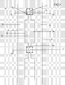
- Fig 3 is a schematic view of one form of electrical pathways interconnecting adjacent LEDs;
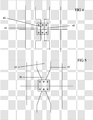
- Fig 4 is a schematic view similar to Fig 3 with an alternative form of LEDs;
- Fig 5 is a schematic view of another form of electrical pathways interconnecting adjacent LEDs.
- A
glazing panel 10 comprises first 11 and second 12 flat, clear, 3mm thick soda lime float glass sheets laminated together by means of a 0.76 mm thick sheet ofPVB 13. Theinner surface 14 of the first glass sheet 11 is provided with a substantially colour neutralCVD coating stack 15 comprising an SiOxCy undercoat and an overlying Sn02:F coating. The coating has a resistance of about 15 ohms per square.Interruptions 16 in thecoating stack 15 formed by laser ablations about 70 microns wide define electrically conducting pathways betweenLEDs 17 which are soldered or attached with an electrically conductive adhesive 19 either side of thelaser ablations 16. Each LED is in direct contact with thecoating 15 of the first glass sheet 11, the spacing shown in FIG 2 being schematic and not representative of the actual positioning.Additional laser ablations 18 divide the array ofLEDs 17 in to individual lines ofLEDs opposite edges - In this embodiment, the LEDs are adapted to provide illumination through the
second glass sheet 12, i.e. without passage through or hindrance by the conductive pathways provided by thecoating layer 15. - The LEDs are arranged in a regular grid at 5cm intervals such that the array of diodes covers substantially the entire area of glazing panel. Each LED has a surface area of about 4mm2.
- In the embodiment of Fig 3, each
LED 17 is a RGB LED having three individual light emitting dies within its packaging. Each die has an associated connection or lead 21,22 23 arranged at the exterior of the packaging which is electrically connected to the its associatedelectrical pathway - The
connection portion 35 ofelectrical pathway 32 has a width of the order of 1 to 2 mm and is in the form of a narrowing of thetransfer portion 34 of the electrical pathway.Transfer portion 34 may have a width of the order of 20 to 60 mm. - In the embodiment of Fig 4, three
individual LEDs - In the embodiment of Fig 5, the narrowing of the
electrical pathway 52 from thetransfer portion 54 to form the connection portion 55 is achieved progressively rather than in a step. This may facilitate current flow within the electrical pathway; it may reduce the risk of creating hot spots; it may be more convenient to manufacture.
Claims (11)
- A glazing panel comprising:a glass substrate;an electrically conductive coating layer;a plurality of LEDs, with adjacent LEDs being electrically connected via electrical pathways defined within the electrically conductive coating layer,the electrical pathways having connection portions adapted to be connected to a connection point or lead of a LED and a transfer portion adapted to provide electrical connection to an adjacent LED;at least some of the electrical pathways comprising connection portions which are provided in the form of a narrowing of the width of their transfer portion.
- A glazing panel in accordance with claim 1, in which at least some of the electrical pathways comprise a transfer portion which is at least 1.5 times wider than their connection portion, preferably at least 5, 10, 15 or 20 times wider.
- glazing panel in accordance with claim 1 or claim 2, in which the narrowing of the electrical pathway from the transfer portion to form the connection portion is achieved progressively.
- A glazing panel in accordance with any preceding claim, in which the adjacent LEDs contain a plurality of light emitting dies.
- A glazing panel in accordance with any preceding claim, in which the adjacent LEDs are RGB LEDs, the red, green, and blue dies of the adjacent LEDs being interconnected via separate electrical pathways.
- A glazing panel in accordance with any preceding claim, in which the electrically conductive coating layer is substantially transparent.
- A glazing panel in accordance with any preceding claim, in which the electrically conductive coating is deposited directly on the surface of the glass substrate.
- A glazing panel in accordance with any preceding claim, in which the glazing panel comprises a second substrate, spaced from the first substrate so that the LEDs are positioned between the two substrates.
- A glazing panel in accordance with claim 8, in which the second substrate is a glass sheet, spaced from the first substrate with an intervening gas filled space..
- A glazing panel in accordance with claim 8, in which the second substrate is a glass sheet and in which the two glass substrates are laminated together via plastics interlayer, preferably comprising a layer of pvb.
- Use of electrical pathways having transfer portions and connection portions provided as a narrowing of the transfer portion to facilitate connection to LEDs and/or reduce electrical losses between LEDs in a glazing structure having adjacent LEDs connected via an electrically conductive coating.
Priority Applications (1)
| Application Number | Priority Date | Filing Date | Title |
|---|---|---|---|
| EP06111121.7A EP1834760B1 (en) | 2006-03-14 | 2006-03-14 | Glass product |
Applications Claiming Priority (1)
| Application Number | Priority Date | Filing Date | Title |
|---|---|---|---|
| EP06111121.7A EP1834760B1 (en) | 2006-03-14 | 2006-03-14 | Glass product |
Publications (2)
| Publication Number | Publication Date |
|---|---|
| EP1834760A1 true EP1834760A1 (en) | 2007-09-19 |
| EP1834760B1 EP1834760B1 (en) | 2014-01-15 |
Family
ID=36809603
Family Applications (1)
| Application Number | Title | Priority Date | Filing Date |
|---|---|---|---|
| EP06111121.7A Expired - Lifetime EP1834760B1 (en) | 2006-03-14 | 2006-03-14 | Glass product |
Country Status (1)
| Country | Link |
|---|---|
| EP (1) | EP1834760B1 (en) |
Cited By (4)
| Publication number | Priority date | Publication date | Assignee | Title |
|---|---|---|---|---|
| DE102008012383B3 (en) * | 2008-03-04 | 2009-06-18 | Fraunhofer-Gesellschaft zur Förderung der angewandten Forschung e.V. | Light-generating wall element |
| WO2009152848A1 (en) * | 2008-06-17 | 2009-12-23 | Agc Flat Glass Europe Sa | Led based housing |
| JP2015029130A (en) * | 2013-03-28 | 2015-02-12 | 東芝ホクト電子株式会社 | LIGHT EMITTING DEVICE, ITS MANUFACTURING METHOD, AND LIGHT EMITTING DEVICE USING DEVICE |
| US20220255493A1 (en) * | 2021-02-11 | 2022-08-11 | Inalfa Roof Systems Group B.V. | Transparent roof panel having an isolated center unit |
Citations (4)
| Publication number | Priority date | Publication date | Assignee | Title |
|---|---|---|---|---|
| JPS61199683A (en) * | 1985-02-28 | 1986-09-04 | Kyocera Corp | Optical printer head |
| JPS62217677A (en) * | 1986-03-18 | 1987-09-25 | Kyocera Corp | Optical printer head |
| GB2362022A (en) * | 2000-03-16 | 2001-11-07 | Beverley Mildred Graham | Double skinned illuminated sign |
| EP1437215A1 (en) * | 2003-01-10 | 2004-07-14 | Glaverbel | Glazing comprising a luminous element |
-
2006
- 2006-03-14 EP EP06111121.7A patent/EP1834760B1/en not_active Expired - Lifetime
Patent Citations (4)
| Publication number | Priority date | Publication date | Assignee | Title |
|---|---|---|---|---|
| JPS61199683A (en) * | 1985-02-28 | 1986-09-04 | Kyocera Corp | Optical printer head |
| JPS62217677A (en) * | 1986-03-18 | 1987-09-25 | Kyocera Corp | Optical printer head |
| GB2362022A (en) * | 2000-03-16 | 2001-11-07 | Beverley Mildred Graham | Double skinned illuminated sign |
| EP1437215A1 (en) * | 2003-01-10 | 2004-07-14 | Glaverbel | Glazing comprising a luminous element |
Non-Patent Citations (2)
| Title |
|---|
| PATENT ABSTRACTS OF JAPAN vol. 011, no. 033 (E - 476) 30 January 1987 (1987-01-30) * |
| PATENT ABSTRACTS OF JAPAN vol. 012, no. 080 (E - 590) 12 March 1988 (1988-03-12) * |
Cited By (5)
| Publication number | Priority date | Publication date | Assignee | Title |
|---|---|---|---|---|
| DE102008012383B3 (en) * | 2008-03-04 | 2009-06-18 | Fraunhofer-Gesellschaft zur Förderung der angewandten Forschung e.V. | Light-generating wall element |
| WO2009152848A1 (en) * | 2008-06-17 | 2009-12-23 | Agc Flat Glass Europe Sa | Led based housing |
| JP2015029130A (en) * | 2013-03-28 | 2015-02-12 | 東芝ホクト電子株式会社 | LIGHT EMITTING DEVICE, ITS MANUFACTURING METHOD, AND LIGHT EMITTING DEVICE USING DEVICE |
| US20220255493A1 (en) * | 2021-02-11 | 2022-08-11 | Inalfa Roof Systems Group B.V. | Transparent roof panel having an isolated center unit |
| US12226978B2 (en) * | 2021-02-11 | 2025-02-18 | Inalfa Roof Systems Group B.V. | Transparent roof panel having an isolated center unit |
Also Published As
| Publication number | Publication date |
|---|---|
| EP1834760B1 (en) | 2014-01-15 |
Similar Documents
| Publication | Publication Date | Title |
|---|---|---|
| US10639869B2 (en) | Vehicular luminous laminated glazed roof, vehicle incorporating same and manufacture | |
| EP2401639B1 (en) | Laminated glass diffused lighting panel and method of manufacturing it | |
| JP6967017B2 (en) | Manufacture of luminous laminated glazing roofs for vehicles, vehicles incorporating them and said glazing roofs | |
| EP1840449B1 (en) | Light Panel | |
| JP6850307B2 (en) | Manufacture of luminous laminated glazing roofs for vehicles, vehicles incorporating them, and the glazing roofs | |
| CN101297606A (en) | Light-emitting structure comprising at least one light-emitting diode, its production and its use | |
| WO2007057459A1 (en) | Glass product | |
| WO2012059126A1 (en) | Laminated inorganic and organic glass diffused lighting panel | |
| CN105122482A (en) | Light-emitting device, manufacturing method thereof, and device using light-emitting device | |
| EA031770B1 (en) | Film-type heating element | |
| KR20130119429A (en) | Method for providing electrical connection(s) in an encapsulated organic light-emitting diode device, and such an oled device | |
| KR20200094170A (en) | Glazing of external light emitting vehicles, vehicles incorporating them, and manufacturing thereof | |
| EP1947693B1 (en) | Plane structure of light-emitting diode lighting apparatus | |
| EP1834760B1 (en) | Glass product | |
| WO2009003523A1 (en) | Glass product | |
| CN101688643B (en) | Led lamp panel | |
| HK1139548A (en) | Glass product | |
| US10493728B2 (en) | Method for supplying an electronic component of a laminated glazing unit with electrical power and laminated glazing unit for implementing said method | |
| HK1133233A (en) | Glass procuct | |
| CN117136137A (en) | Vehicle skylight glass with integrated light source | |
| HK1138563A (en) | Glass product |
Legal Events
| Date | Code | Title | Description |
|---|---|---|---|
| PUAI | Public reference made under article 153(3) epc to a published international application that has entered the european phase |
Free format text: ORIGINAL CODE: 0009012 |
|
| AK | Designated contracting states |
Kind code of ref document: A1 Designated state(s): AT BE BG CH CY CZ DE DK EE ES FI FR GB GR HU IE IS IT LI LT LU LV MC NL PL PT RO SE SI SK TR |
|
| AX | Request for extension of the european patent |
Extension state: AL BA HR MK YU |
|
| RAP1 | Party data changed (applicant data changed or rights of an application transferred) |
Owner name: AGC FLAT GLASS EUROPE SA |
|
| 17P | Request for examination filed |
Effective date: 20071001 |
|
| 17Q | First examination report despatched |
Effective date: 20071102 |
|
| AKX | Designation fees paid |
Designated state(s): AT BE BG CH CY CZ DE DK EE ES FI FR GB GR HU IE IS IT LI LT LU LV MC NL PL PT RO SE SI SK TR |
|
| RAP1 | Party data changed (applicant data changed or rights of an application transferred) |
Owner name: AGC GLASS EUROPE |
|
| GRAP | Despatch of communication of intention to grant a patent |
Free format text: ORIGINAL CODE: EPIDOSNIGR1 |
|
| INTG | Intention to grant announced |
Effective date: 20130823 |
|
| RIC1 | Information provided on ipc code assigned before grant |
Ipc: H01L 25/075 20060101ALI20130814BHEP Ipc: H01L 33/00 20100101ALI20130814BHEP Ipc: E06B 3/66 20060101ALI20130814BHEP Ipc: H01L 33/62 20100101ALN20130814BHEP Ipc: F21K 99/00 20100101ALN20130814BHEP Ipc: B32B 17/10 20060101AFI20130814BHEP Ipc: F21V 33/00 20060101ALI20130814BHEP |
|
| GRAS | Grant fee paid |
Free format text: ORIGINAL CODE: EPIDOSNIGR3 |
|
| GRAA | (expected) grant |
Free format text: ORIGINAL CODE: 0009210 |
|
| AK | Designated contracting states |
Kind code of ref document: B1 Designated state(s): AT BE BG CH CY CZ DE DK EE ES FI FR GB GR HU IE IS IT LI LT LU LV MC NL PL PT RO SE SI SK TR |
|
| REG | Reference to a national code |
Ref country code: GB Ref legal event code: FG4D Ref country code: CH Ref legal event code: EP |
|
| REG | Reference to a national code |
Ref country code: AT Ref legal event code: REF Ref document number: 649611 Country of ref document: AT Kind code of ref document: T Effective date: 20140215 |
|
| REG | Reference to a national code |
Ref country code: DE Ref legal event code: R096 Ref document number: 602006040054 Country of ref document: DE Effective date: 20140220 |
|
| REG | Reference to a national code |
Ref country code: IE Ref legal event code: FG4D |
|
| RAP2 | Party data changed (patent owner data changed or rights of a patent transferred) |
Owner name: AGC GLASS EUROPE |
|
| REG | Reference to a national code |
Ref country code: NL Ref legal event code: VDEP Effective date: 20140115 |
|
| REG | Reference to a national code |
Ref country code: AT Ref legal event code: MK05 Ref document number: 649611 Country of ref document: AT Kind code of ref document: T Effective date: 20140115 |
|
| REG | Reference to a national code |
Ref country code: LT Ref legal event code: MG4D |
|
| PG25 | Lapsed in a contracting state [announced via postgrant information from national office to epo] |
Ref country code: IS Free format text: LAPSE BECAUSE OF FAILURE TO SUBMIT A TRANSLATION OF THE DESCRIPTION OR TO PAY THE FEE WITHIN THE PRESCRIBED TIME-LIMIT Effective date: 20140515 Ref country code: LT Free format text: LAPSE BECAUSE OF FAILURE TO SUBMIT A TRANSLATION OF THE DESCRIPTION OR TO PAY THE FEE WITHIN THE PRESCRIBED TIME-LIMIT Effective date: 20140115 |
|
| PGFP | Annual fee paid to national office [announced via postgrant information from national office to epo] |
Ref country code: BE Payment date: 20140324 Year of fee payment: 9 |
|
| PG25 | Lapsed in a contracting state [announced via postgrant information from national office to epo] |
Ref country code: SE Free format text: LAPSE BECAUSE OF FAILURE TO SUBMIT A TRANSLATION OF THE DESCRIPTION OR TO PAY THE FEE WITHIN THE PRESCRIBED TIME-LIMIT Effective date: 20140115 Ref country code: AT Free format text: LAPSE BECAUSE OF FAILURE TO SUBMIT A TRANSLATION OF THE DESCRIPTION OR TO PAY THE FEE WITHIN THE PRESCRIBED TIME-LIMIT Effective date: 20140115 Ref country code: CY Free format text: LAPSE BECAUSE OF FAILURE TO SUBMIT A TRANSLATION OF THE DESCRIPTION OR TO PAY THE FEE WITHIN THE PRESCRIBED TIME-LIMIT Effective date: 20140115 Ref country code: ES Free format text: LAPSE BECAUSE OF FAILURE TO SUBMIT A TRANSLATION OF THE DESCRIPTION OR TO PAY THE FEE WITHIN THE PRESCRIBED TIME-LIMIT Effective date: 20140115 Ref country code: NL Free format text: LAPSE BECAUSE OF FAILURE TO SUBMIT A TRANSLATION OF THE DESCRIPTION OR TO PAY THE FEE WITHIN THE PRESCRIBED TIME-LIMIT Effective date: 20140115 Ref country code: PT Free format text: LAPSE BECAUSE OF FAILURE TO SUBMIT A TRANSLATION OF THE DESCRIPTION OR TO PAY THE FEE WITHIN THE PRESCRIBED TIME-LIMIT Effective date: 20140515 Ref country code: FI Free format text: LAPSE BECAUSE OF FAILURE TO SUBMIT A TRANSLATION OF THE DESCRIPTION OR TO PAY THE FEE WITHIN THE PRESCRIBED TIME-LIMIT Effective date: 20140115 |
|
| PG25 | Lapsed in a contracting state [announced via postgrant information from national office to epo] |
Ref country code: LV Free format text: LAPSE BECAUSE OF FAILURE TO SUBMIT A TRANSLATION OF THE DESCRIPTION OR TO PAY THE FEE WITHIN THE PRESCRIBED TIME-LIMIT Effective date: 20140115 Ref country code: BE Free format text: LAPSE BECAUSE OF FAILURE TO SUBMIT A TRANSLATION OF THE DESCRIPTION OR TO PAY THE FEE WITHIN THE PRESCRIBED TIME-LIMIT Effective date: 20140115 |
|
| REG | Reference to a national code |
Ref country code: DE Ref legal event code: R097 Ref document number: 602006040054 Country of ref document: DE |
|
| PG25 | Lapsed in a contracting state [announced via postgrant information from national office to epo] |
Ref country code: LU Free format text: LAPSE BECAUSE OF FAILURE TO SUBMIT A TRANSLATION OF THE DESCRIPTION OR TO PAY THE FEE WITHIN THE PRESCRIBED TIME-LIMIT Effective date: 20140314 Ref country code: EE Free format text: LAPSE BECAUSE OF FAILURE TO SUBMIT A TRANSLATION OF THE DESCRIPTION OR TO PAY THE FEE WITHIN THE PRESCRIBED TIME-LIMIT Effective date: 20140115 Ref country code: RO Free format text: LAPSE BECAUSE OF FAILURE TO SUBMIT A TRANSLATION OF THE DESCRIPTION OR TO PAY THE FEE WITHIN THE PRESCRIBED TIME-LIMIT Effective date: 20140115 Ref country code: DK Free format text: LAPSE BECAUSE OF FAILURE TO SUBMIT A TRANSLATION OF THE DESCRIPTION OR TO PAY THE FEE WITHIN THE PRESCRIBED TIME-LIMIT Effective date: 20140115 Ref country code: CZ Free format text: LAPSE BECAUSE OF FAILURE TO SUBMIT A TRANSLATION OF THE DESCRIPTION OR TO PAY THE FEE WITHIN THE PRESCRIBED TIME-LIMIT Effective date: 20140115 |
|
| REG | Reference to a national code |
Ref country code: CH Ref legal event code: PL |
|
| PLBE | No opposition filed within time limit |
Free format text: ORIGINAL CODE: 0009261 |
|
| STAA | Information on the status of an ep patent application or granted ep patent |
Free format text: STATUS: NO OPPOSITION FILED WITHIN TIME LIMIT |
|
| PG25 | Lapsed in a contracting state [announced via postgrant information from national office to epo] |
Ref country code: PL Free format text: LAPSE BECAUSE OF FAILURE TO SUBMIT A TRANSLATION OF THE DESCRIPTION OR TO PAY THE FEE WITHIN THE PRESCRIBED TIME-LIMIT Effective date: 20140115 Ref country code: SK Free format text: LAPSE BECAUSE OF FAILURE TO SUBMIT A TRANSLATION OF THE DESCRIPTION OR TO PAY THE FEE WITHIN THE PRESCRIBED TIME-LIMIT Effective date: 20140115 |
|
| 26N | No opposition filed |
Effective date: 20141016 |
|
| GBPC | Gb: european patent ceased through non-payment of renewal fee |
Effective date: 20140415 |
|
| REG | Reference to a national code |
Ref country code: IE Ref legal event code: MM4A |
|
| PG25 | Lapsed in a contracting state [announced via postgrant information from national office to epo] |
Ref country code: LI Free format text: LAPSE BECAUSE OF NON-PAYMENT OF DUE FEES Effective date: 20140331 Ref country code: IE Free format text: LAPSE BECAUSE OF NON-PAYMENT OF DUE FEES Effective date: 20140314 Ref country code: GB Free format text: LAPSE BECAUSE OF NON-PAYMENT OF DUE FEES Effective date: 20140415 Ref country code: CH Free format text: LAPSE BECAUSE OF NON-PAYMENT OF DUE FEES Effective date: 20140331 |
|
| REG | Reference to a national code |
Ref country code: DE Ref legal event code: R097 Ref document number: 602006040054 Country of ref document: DE Effective date: 20141016 |
|
| PG25 | Lapsed in a contracting state [announced via postgrant information from national office to epo] |
Ref country code: SI Free format text: LAPSE BECAUSE OF FAILURE TO SUBMIT A TRANSLATION OF THE DESCRIPTION OR TO PAY THE FEE WITHIN THE PRESCRIBED TIME-LIMIT Effective date: 20140115 |
|
| REG | Reference to a national code |
Ref country code: FR Ref legal event code: PLFP Year of fee payment: 11 |
|
| PG25 | Lapsed in a contracting state [announced via postgrant information from national office to epo] |
Ref country code: BG Free format text: LAPSE BECAUSE OF FAILURE TO SUBMIT A TRANSLATION OF THE DESCRIPTION OR TO PAY THE FEE WITHIN THE PRESCRIBED TIME-LIMIT Effective date: 20140115 Ref country code: MC Free format text: LAPSE BECAUSE OF FAILURE TO SUBMIT A TRANSLATION OF THE DESCRIPTION OR TO PAY THE FEE WITHIN THE PRESCRIBED TIME-LIMIT Effective date: 20140115 |
|
| PG25 | Lapsed in a contracting state [announced via postgrant information from national office to epo] |
Ref country code: GR Free format text: LAPSE BECAUSE OF FAILURE TO SUBMIT A TRANSLATION OF THE DESCRIPTION OR TO PAY THE FEE WITHIN THE PRESCRIBED TIME-LIMIT Effective date: 20140416 |
|
| PG25 | Lapsed in a contracting state [announced via postgrant information from national office to epo] |
Ref country code: TR Free format text: LAPSE BECAUSE OF FAILURE TO SUBMIT A TRANSLATION OF THE DESCRIPTION OR TO PAY THE FEE WITHIN THE PRESCRIBED TIME-LIMIT Effective date: 20140115 Ref country code: HU Free format text: LAPSE BECAUSE OF FAILURE TO SUBMIT A TRANSLATION OF THE DESCRIPTION OR TO PAY THE FEE WITHIN THE PRESCRIBED TIME-LIMIT; INVALID AB INITIO Effective date: 20060314 |
|
| REG | Reference to a national code |
Ref country code: FR Ref legal event code: PLFP Year of fee payment: 12 |
|
| REG | Reference to a national code |
Ref country code: FR Ref legal event code: PLFP Year of fee payment: 13 |
|
| PGFP | Annual fee paid to national office [announced via postgrant information from national office to epo] |
Ref country code: FR Payment date: 20230208 Year of fee payment: 18 |
|
| PGFP | Annual fee paid to national office [announced via postgrant information from national office to epo] |
Ref country code: IT Payment date: 20230213 Year of fee payment: 18 Ref country code: DE Payment date: 20230131 Year of fee payment: 18 |
|
| REG | Reference to a national code |
Ref country code: DE Ref legal event code: R119 Ref document number: 602006040054 Country of ref document: DE |
|
| PG25 | Lapsed in a contracting state [announced via postgrant information from national office to epo] |
Ref country code: DE Free format text: LAPSE BECAUSE OF NON-PAYMENT OF DUE FEES Effective date: 20241001 |
|
| PG25 | Lapsed in a contracting state [announced via postgrant information from national office to epo] |
Ref country code: FR Free format text: LAPSE BECAUSE OF NON-PAYMENT OF DUE FEES Effective date: 20240331 |
|
| PG25 | Lapsed in a contracting state [announced via postgrant information from national office to epo] |
Ref country code: FR Free format text: LAPSE BECAUSE OF NON-PAYMENT OF DUE FEES Effective date: 20240331 Ref country code: DE Free format text: LAPSE BECAUSE OF NON-PAYMENT OF DUE FEES Effective date: 20241001 |
|
| PG25 | Lapsed in a contracting state [announced via postgrant information from national office to epo] |
Ref country code: IT Free format text: LAPSE BECAUSE OF NON-PAYMENT OF DUE FEES Effective date: 20240314 |