EP1834711A1 - Method and apparatus for separating glass leaves and intermediate film from crushed glass laminate - Google Patents
Method and apparatus for separating glass leaves and intermediate film from crushed glass laminate Download PDFInfo
- Publication number
- EP1834711A1 EP1834711A1 EP20050816732 EP05816732A EP1834711A1 EP 1834711 A1 EP1834711 A1 EP 1834711A1 EP 20050816732 EP20050816732 EP 20050816732 EP 05816732 A EP05816732 A EP 05816732A EP 1834711 A1 EP1834711 A1 EP 1834711A1
- Authority
- EP
- European Patent Office
- Prior art keywords
- laminated glass
- glass pane
- stripping
- intermediate film
- crushed laminated
- Prior art date
- Legal status (The legal status is an assumption and is not a legal conclusion. Google has not performed a legal analysis and makes no representation as to the accuracy of the status listed.)
- Withdrawn
Links
- 239000011521 glass Substances 0.000 title claims abstract description 72
- 239000005340 laminated glass Substances 0.000 title claims abstract description 70
- 238000000034 method Methods 0.000 title claims description 22
- 239000007864 aqueous solution Substances 0.000 claims abstract description 35
- 238000007598 dipping method Methods 0.000 claims abstract description 23
- XLYOFNOQVPJJNP-UHFFFAOYSA-N water Substances O XLYOFNOQVPJJNP-UHFFFAOYSA-N 0.000 claims abstract description 8
- 238000001035 drying Methods 0.000 claims abstract description 7
- 239000002184 metal Substances 0.000 claims description 11
- 239000003795 chemical substances by application Substances 0.000 claims description 2
- 230000000881 depressing effect Effects 0.000 claims description 2
- 230000005587 bubbling Effects 0.000 claims 1
- 238000007790 scraping Methods 0.000 claims 1
- 238000000926 separation method Methods 0.000 description 4
- 238000011144 upstream manufacturing Methods 0.000 description 3
- NBIIXXVUZAFLBC-UHFFFAOYSA-N Phosphoric acid Chemical compound OP(O)(O)=O NBIIXXVUZAFLBC-UHFFFAOYSA-N 0.000 description 2
- DQXBYHZEEUGOBF-UHFFFAOYSA-N but-3-enoic acid;ethene Chemical compound C=C.OC(=O)CC=C DQXBYHZEEUGOBF-UHFFFAOYSA-N 0.000 description 2
- 239000005038 ethylene vinyl acetate Substances 0.000 description 2
- -1 fluorine ion Chemical compound 0.000 description 2
- OSWPMRLSEDHDFF-UHFFFAOYSA-N methyl salicylate Chemical compound COC(=O)C1=CC=CC=C1O OSWPMRLSEDHDFF-UHFFFAOYSA-N 0.000 description 2
- 230000035515 penetration Effects 0.000 description 2
- 229920001200 poly(ethylene-vinyl acetate) Polymers 0.000 description 2
- 229920002037 poly(vinyl butyral) polymer Polymers 0.000 description 2
- 0 CC(CCO)*1CCCCC1 Chemical compound CC(CCO)*1CCCCC1 0.000 description 1
- QXRHEATXNGVTIQ-UHFFFAOYSA-N CC1CCC(C)(CCO)CC1 Chemical compound CC1CCC(C)(CCO)CC1 QXRHEATXNGVTIQ-UHFFFAOYSA-N 0.000 description 1
- KRHYYFGTRYWZRS-UHFFFAOYSA-M Fluoride anion Chemical compound [F-] KRHYYFGTRYWZRS-UHFFFAOYSA-M 0.000 description 1
- 239000004698 Polyethylene Substances 0.000 description 1
- 229910000147 aluminium phosphate Inorganic materials 0.000 description 1
- 150000001875 compounds Chemical class 0.000 description 1
- 238000011109 contamination Methods 0.000 description 1
- 239000006063 cullet Substances 0.000 description 1
- 238000007865 diluting Methods 0.000 description 1
- 230000000694 effects Effects 0.000 description 1
- 239000012530 fluid Substances 0.000 description 1
- 238000010438 heat treatment Methods 0.000 description 1
- 239000007788 liquid Substances 0.000 description 1
- 239000000463 material Substances 0.000 description 1
- 229960001047 methyl salicylate Drugs 0.000 description 1
- LNOPIUAQISRISI-UHFFFAOYSA-N n'-hydroxy-2-propan-2-ylsulfonylethanimidamide Chemical compound CC(C)S(=O)(=O)CC(N)=NO LNOPIUAQISRISI-UHFFFAOYSA-N 0.000 description 1
- 229920000573 polyethylene Polymers 0.000 description 1
- 239000002861 polymer material Substances 0.000 description 1
- 238000004064 recycling Methods 0.000 description 1
- 229920005989 resin Polymers 0.000 description 1
- 239000011347 resin Substances 0.000 description 1
- 239000000243 solution Substances 0.000 description 1
- 239000004094 surface-active agent Substances 0.000 description 1
- 230000008961 swelling Effects 0.000 description 1
- 239000002699 waste material Substances 0.000 description 1
Images




Classifications
-
- B—PERFORMING OPERATIONS; TRANSPORTING
- B29—WORKING OF PLASTICS; WORKING OF SUBSTANCES IN A PLASTIC STATE IN GENERAL
- B29B—PREPARATION OR PRETREATMENT OF THE MATERIAL TO BE SHAPED; MAKING GRANULES OR PREFORMS; RECOVERY OF PLASTICS OR OTHER CONSTITUENTS OF WASTE MATERIAL CONTAINING PLASTICS
- B29B17/00—Recovery of plastics or other constituents of waste material containing plastics
- B29B17/02—Separating plastics from other materials
-
- C—CHEMISTRY; METALLURGY
- C03—GLASS; MINERAL OR SLAG WOOL
- C03C—CHEMICAL COMPOSITION OF GLASSES, GLAZES OR VITREOUS ENAMELS; SURFACE TREATMENT OF GLASS; SURFACE TREATMENT OF FIBRES OR FILAMENTS MADE FROM GLASS, MINERALS OR SLAGS; JOINING GLASS TO GLASS OR OTHER MATERIALS
- C03C1/00—Ingredients generally applicable to manufacture of glasses, glazes, or vitreous enamels
- C03C1/02—Pretreated ingredients
- C03C1/024—Chemical treatment of cullet or glass fibres
-
- B—PERFORMING OPERATIONS; TRANSPORTING
- B29—WORKING OF PLASTICS; WORKING OF SUBSTANCES IN A PLASTIC STATE IN GENERAL
- B29B—PREPARATION OR PRETREATMENT OF THE MATERIAL TO BE SHAPED; MAKING GRANULES OR PREFORMS; RECOVERY OF PLASTICS OR OTHER CONSTITUENTS OF WASTE MATERIAL CONTAINING PLASTICS
- B29B17/00—Recovery of plastics or other constituents of waste material containing plastics
- B29B17/02—Separating plastics from other materials
- B29B2017/0213—Specific separating techniques
- B29B2017/0286—Cleaning means used for separation
- B29B2017/0289—Washing the materials in liquids
-
- B—PERFORMING OPERATIONS; TRANSPORTING
- B29—WORKING OF PLASTICS; WORKING OF SUBSTANCES IN A PLASTIC STATE IN GENERAL
- B29B—PREPARATION OR PRETREATMENT OF THE MATERIAL TO BE SHAPED; MAKING GRANULES OR PREFORMS; RECOVERY OF PLASTICS OR OTHER CONSTITUENTS OF WASTE MATERIAL CONTAINING PLASTICS
- B29B17/00—Recovery of plastics or other constituents of waste material containing plastics
- B29B17/04—Disintegrating plastics, e.g. by milling
- B29B2017/0424—Specific disintegrating techniques; devices therefor
- B29B2017/0436—Immersion baths
-
- B—PERFORMING OPERATIONS; TRANSPORTING
- B29—WORKING OF PLASTICS; WORKING OF SUBSTANCES IN A PLASTIC STATE IN GENERAL
- B29K—INDEXING SCHEME ASSOCIATED WITH SUBCLASSES B29B, B29C OR B29D, RELATING TO MOULDING MATERIALS OR TO MATERIALS FOR MOULDS, REINFORCEMENTS, FILLERS OR PREFORMED PARTS, e.g. INSERTS
- B29K2031/00—Use of polyvinylesters or derivatives thereof as moulding material
- B29K2031/04—Polymers of vinyl acetate, e.g. PVAc, i.e. polyvinyl acetate
-
- B—PERFORMING OPERATIONS; TRANSPORTING
- B29—WORKING OF PLASTICS; WORKING OF SUBSTANCES IN A PLASTIC STATE IN GENERAL
- B29K—INDEXING SCHEME ASSOCIATED WITH SUBCLASSES B29B, B29C OR B29D, RELATING TO MOULDING MATERIALS OR TO MATERIALS FOR MOULDS, REINFORCEMENTS, FILLERS OR PREFORMED PARTS, e.g. INSERTS
- B29K2709/00—Use of inorganic materials not provided for in groups B29K2703/00 - B29K2707/00, for preformed parts, e.g. for inserts
- B29K2709/08—Glass
-
- B—PERFORMING OPERATIONS; TRANSPORTING
- B29—WORKING OF PLASTICS; WORKING OF SUBSTANCES IN A PLASTIC STATE IN GENERAL
- B29L—INDEXING SCHEME ASSOCIATED WITH SUBCLASS B29C, RELATING TO PARTICULAR ARTICLES
- B29L2031/00—Other particular articles
- B29L2031/778—Windows
- B29L2031/7782—Glazing
-
- C—CHEMISTRY; METALLURGY
- C03—GLASS; MINERAL OR SLAG WOOL
- C03C—CHEMICAL COMPOSITION OF GLASSES, GLAZES OR VITREOUS ENAMELS; SURFACE TREATMENT OF GLASS; SURFACE TREATMENT OF FIBRES OR FILAMENTS MADE FROM GLASS, MINERALS OR SLAGS; JOINING GLASS TO GLASS OR OTHER MATERIALS
- C03C2218/00—Methods for coating glass
- C03C2218/30—Aspects of methods for coating glass not covered above
- C03C2218/32—After-treatment
- C03C2218/328—Partly or completely removing a coating
-
- Y—GENERAL TAGGING OF NEW TECHNOLOGICAL DEVELOPMENTS; GENERAL TAGGING OF CROSS-SECTIONAL TECHNOLOGIES SPANNING OVER SEVERAL SECTIONS OF THE IPC; TECHNICAL SUBJECTS COVERED BY FORMER USPC CROSS-REFERENCE ART COLLECTIONS [XRACs] AND DIGESTS
- Y02—TECHNOLOGIES OR APPLICATIONS FOR MITIGATION OR ADAPTATION AGAINST CLIMATE CHANGE
- Y02W—CLIMATE CHANGE MITIGATION TECHNOLOGIES RELATED TO WASTEWATER TREATMENT OR WASTE MANAGEMENT
- Y02W30/00—Technologies for solid waste management
- Y02W30/50—Reuse, recycling or recovery technologies
- Y02W30/62—Plastics recycling; Rubber recycling
Definitions
- the present invention relates generally to a method and apparatus for separating glass segments and an intermediate film of a laminated glass pane, particularly to a method and apparatus for separating glass segments and an intermediate film from a crushed laminated glass pane.
- a laminated glass pane is used for building glass panes, vehicle glass pane, and the like, the laminated glass pane being improved in its strength by sandwiching an intermediate film between two glasses.
- a large amount of waste limited glass panes are generated by discarding building glass panes and vehicle glass panes.
- Conventional recycling methods of laminated glass panes are known, for example, a method for separating glass segments and an intermediate film by crushing a laminated glass pane and subsequently providing tensile strain to the intermediate film (refer to Japanese Patent Publication No.
- a first aspect of the present invention is an apparatus for separating glass segments and an intermediate film from a crushed laminated glass pane.
- the apparatus comprises dipping means for dipping the crushed laminated glass pane aqueous solution, and stripping means for striping the glass segments from the intermediate film while the crushed laminated glass pane being dipped in the aqueous solution.
- a second aspect of the present invention is a method for separating glass segments and an intermediate film from a crushed laminated glass pane.
- the method comprises the step of dipping the crushed laminated glass pane aqueous solution, and stripping the glass segments from the intermediate film while the crushed laminated glass pane being dipped in the aqueous solution.
- the separation of glass segments and an intermediate film from a laminated glass pane may be implemented in a small amount of time.
- FIG. shows an embodiment of a separating apparatus 10 according to the present invention
- FIG.2 a sectional view of the separating apparatus in FIG. 1.
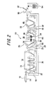
- the separating apparatus 10 comprises a dipping zone 16 in which a crushed laminated glass pane 12 is transported with sandwiched between mesh conveyors 22 and 24 and is dipped in an aqueous solution 18; a separating zone 30 in which the crushed laminated glass pane 12 transferred out of the dipping zone 16 is transported with sandwiched between mesh conveyors 26 and 28 in the aqueous solution 18, and the glass segments are stripped from the intermediate film during the transportation of the glass pane to collect the glass segments; and a rinsing / drying zone 46 in which the intermediate film transferred out of the separating zone 30 is transported with sandwiched between mesh conveyors 32 and 33, is rinsed with water and is dried.
- the dipping zone 16 and separating zone 30 are driven by a wall 29, and the separating zone 30 and rinsing / drying zone 46 by a wall 45.
- the intermediate film to be processed in the separating apparatus is made of polymer materials, for example PVB (polyvinyl butyral) or EVA (ethylene vinyl acetate).
- a crusher (not shown) is provided at a stage proceeding to the separating apparatus 10.
- the overlapped mesh conveyors 22 and 24 are traveling up and down in a meandering manner in a receptacle 20 filled with aqueous solution 18.
- the aqueous solution 18 is a warm water, for example.
- the aqueous solution may include at least one type of sulfamic acid, phosphoric acid, compound including fluorine ion, and methyl salicylate, as a separating agent.
- the aqueous solution may include an alkaline diluting fluid (alkaline treated water of PH11) or may include a surface active agent.
- the crushed laminated glass pane 12 is sandwiched between the mesh conveyors 22 and 24 at the entrance of the dipping zone 16, and is dipped in the aqueous solution held at a predetermined temperature, 30-70°C for examples, for 10-15 minutes during a meandering travel of the mesh conveyors. In this period, the aqueous solution 18 is penetrated into between the glass segments and intermediate film so as to facilitate the separation of the glass segments at a post-process.
- a heater (not shown) for heating the aqueous solution.
- the temperature of the aqueous solution is in a range of 30-70°C is based on the face that the softening temperature of the intermediate film is required to be 30°Cor more in order to extend easily the softened intermediate film, and if the temperature of the aqueous solution is 70°C or more, the intermediate film is softened too much so that the crushed glass segments are embedded in the intermediate film, resulting in the difficulty of effective separation of the glass segments and intermediate film. More preferable temperature of the aqueous solution is approximately 50°C which is 20°C higher than the softening temperature of the intermediate film.
- the aqueous solution is supplied to the receptacle 20 of the dipping zone 16 through a value 60.
- the aqueous solution is sucked up from the bottom of receptacle 20 by a pump 62, is filtered by a filter 64, and is flowed back to the upper portion of the receptacle 20.
- the crushed laminated glass pane 12 is ejected out of the overlapped mesh conveyors 22 and 24 at the exit of the dipping zone 16 and transferred to the separating zone 30.
- the crushed laminated glass pane 12 is sandwiched by the mesh conveyors 26 and 28 at the entrance of the separating zone 30, the mesh conveyors being traveling in a meandering manner.
- the separating zone 30 is filled with the aqueous solution 18 an well as the dipping zone 16.
- the aqueous solution is held at a temperature of 30°C-70°C an described above.
- a heater (not shown) is provided in the separating zone 30.
- an umbonate roll 34 and a metal roll brush 36 are provided opposing to each other with interposing the overlapped mesh conveyors 26 and 28 at two locations in the course of the overlapped mesh conveyors.
- protrusions 38 of the umbonate roll 34 push the intermediated film 44 carried the glass segments 42 thereon through the mesh of the conveyor (the cross-section thereof is designated by reference numeral 40 in the figure).
- the glass segments carried on the protruded intermediate film pushed by the protrusion are stripped by means of the metal roll brush 36. While only two sets of the umbonate roll and metal roll brush are shown in FIG.2 to simplify the drawing, four-six sets of them may preferably be provided.
- the separated glass segments are deposited on the bottom of a receptacle 66 in the separating zone 30.
- the solution flow is formed by supplying further aqueous solution though a pipe 61.
- the gathered glass segments are exhausted by means of a suction pipe 68 provided at the bottom of the receptacle 66 and are rinsed with water to be collected.
- a drain pipe 70 exhausts only the aqueous solution at the bottom of the receptacle 66.
- a connection pipe 71 connects the receptacle 20 of the dipping zone and the receptacle 66 of the separating zone.
- the intermediate film 44 from both sides thereof the glass segments 42 have been stripped is transferred to the rinsing / drying zone 46.
- the intermediate film 44 is sandwiched between the mesh conveyors 32 and 33 which are traveling in a meandering manner.
- the intermediate film 44 is rinsed by means of a washer such as a shower device (not shown), and subsequently is dried by means of a dryer 50. If warm water is used as the aqueous solution, the rinsing by the washer may be omitted.
- the dried intermediate film 44 is grasped by a suction device 52 and are stacked on a carriage 54. In this case, if need arises, a polyethylene sheet is inserted between the intermediate sheets so that the films are not adhered to each other.
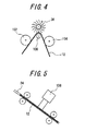
- FIG.4 shows an example in which only a metal roll brush is used for stripping the glass segments.
- mesh conveyors are omitted for simplification.
- Two hold down roll 102 and 14 are arranged on the both sides of one small diameter roll 100 to strip the glass segments by means of the metal roll brush 36 from the crushed laminated glass pane 12 traveling in a convex manner.
- FIG.5 shows another example in which a vibration generator 106 is provided at the upstream side of a metal roll brush for mechanical stripping.
- the vibration generator 106 is arranged in proximity to the crushed laminated glass pane 12 traveling with sandwiched between mesh conveyors 24.
- the vibration generator may be a vibrator or air-knocker.
- vibration generator 106 is arranged in proximity to the mesh conveyor 24 in this example, it may be provided at any location in the aqueous solution within the separating zone 30.
- an ultrasonic generator or bubble generator may be utilized as a method for facilitating the penetration of aqueous solution into between the glass segments and intermediate film.
- Such ultrasonic generator or bubble generator may be provided at any location in the aqueous solution.
- the glass segments are stripped by means of the metal roller brush, the glass segments may be stripped by extending the crushed laminated glass pane.
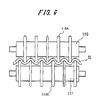
- the stripping means comprises two flanged rolls 110 and 112 arranged opposing to each other.
- the flange of the roll 110 is designated by reference number 110A, and the flange of the roll 112 by reference numeral 112A.
- Each roll is provided with such flanges at intervals.
- the flanges 110A and 112A are alternately arranged to engage with each other.
- the crushed laminated glass pane 12 is transported in a direction perpendicular to the surface of the sheet on which FIG.6 is drawn.
- a ladder conveyor is preferably used for the transportation of the glass pane 12.
- FIGS. 7A and 7B Two typical structures of the ladder conveyor are shown in FIGS. 7A and 7B.
- the ladder conveyor shown in FIG.7A comprises a chain 114C provided across two roller 114A and 114B, a chain 116C provided across two roller 116A and 116B, and bars 118 (such as round bars and pipes) extended across these chains.
- the ladder conveyor shown in FIG.7B comprises a plurality of members 120C arranged in parallel such as chains, ropes, V-belts, wires and the like, the member being provided across two rollers 120A and 120B.
- the ladder conveyor in FIG.7B is used for the stripping means shown in FIG.6 to transport the crushed laminated glass pane.
- the crushed laminated glass pane is sandwiched between overlapped ladder conveyors, or is mounted on the ladder conveyor.
- the crushed laminated glass pane is transported up and down as shown in FIG.2, the crushed laminated glass pane is transported with sandwiched between the overlapped ladder conveyors.
- the crushed laminated glass pane 12 transported by the ladder conveyor(s) is inserted between the flanges 110A and 112A rotated with the rolls 110 and 112.
- the intermediate film of the crushed laminated glass pane is extended by the engagement of the flange 110A and 112B.
- the glass segments are stripped from the intermediate film due to the extension of the intermediate film.
- FIG.8 Further example of means for stripping the glass segments by extending the intermediate film is illustrated in FIG.8.
- Two gears 122 and 124 are used in this example.
- reference numerals 126 and 128 designate holding rollers.
- the crushed laminated glass pane 12 is transported in a direction shown by an arrow 130.
- the ladder conveyor in FIG.7A is utilized.
- the intermediate film is extended by the engagement of respective teeth 122A and 124A of the gears 122 and 124 so that the glass segments are stripped from the intermediate film in the same manner as in FIG.6.
- FIGS. 9A and 9B and 9C Further example of means for stripping the glass segments by the extension of the intermediate film is shown in FIGS. 9A and 9B and 9C.
- the stripping means comprises two pressure plates 130 and 132 each having protrusions as shown in FIG.9A.
- the protrusion are designated by reference numerals 130A and 132A.
- protrusion is a convex one as shown in FIG.9B, and another example a toothed one as shown in FIG.9C. These protrusion are arranged so as to be engaged to each other when the pressure plates 130 and 132 are approached.
- the crushed laminated glass pane 12 is transported to between the pressure plates 130 and 132 being apart from each other. Subsequently, the pressure plates are repeatedly pressed to each other so that the protrusions 130A and 132A are engaged to each other. As a result, the intermediate film is extended so that the glass segments are stripped from the intermediate film. Alternatively, the pressure plates may be pressed to each other for a predetermined period to hold the extension state of the crushed laminated glass pane for a predetermined period.
- the crushed laminated glass pane is intermittently transported to carry out the stripping process in units of small area of the glass pane. Where the pressure plates are large, the entire of one sheet of the crushed laminated glass pane may be processed at one time.
- FIGS. 10A and 10B Further example of means for stripping the glass segments by the extension of the intermediate film is shown is FIGS. 10A and 10B.
- FIG.10A is a sectional side elevation of the means and FIG.10B a sectional view taken along X-X line in FIG.10A.
- the stripping means comprises members 140A and 140B for clipping the crushed laminated glass pane 12 at plural positions from both sides thereof, and a pressure member 142 for depressing the clipped glass pane at plural positions other than the clipped positions thereof.
- the crushed laminated glass pane 12 is transported to between the clipping members 140A and 140B being apart from each other, and is fixed by clipping the glass pane with the clipping members.
- the pressure member 142 is repeatedly pushed down to depress and extend the intermediate film, resulting in the stripping of glass segments from the intermediate film
- the pressure member 142 may be borne down on the crushed laminated glass pane for a predetermined period to hold the extension state of the glass pane for a predetermined period.
- the pressure members 142 may be provided on both sides of the crushed laminated glass pane 12 (this example is not shown in the figure). In this stripping means, the crushed laminated glass pane is intermittently transported to carry out stripping process in units of small area of the glass pane. Where the pressure member is large, the entire of one sheet of the crushed laminated glass pane may be processed at one time.
- the glass segments and intermediate film separated by means of the method or apparatus according to the present invention for separating the glass segment and intermediate film from the crushed laminated glass pane may be reutilized to glass products as cullet and to a resin material, respectively.
Landscapes
- Engineering & Computer Science (AREA)
- Chemical & Material Sciences (AREA)
- General Chemical & Material Sciences (AREA)
- Life Sciences & Earth Sciences (AREA)
- Mechanical Engineering (AREA)
- Chemical Kinetics & Catalysis (AREA)
- Environmental & Geological Engineering (AREA)
- Geochemistry & Mineralogy (AREA)
- Materials Engineering (AREA)
- Organic Chemistry (AREA)
- Processing Of Solid Wastes (AREA)
- Joining Of Glass To Other Materials (AREA)
- Separation, Recovery Or Treatment Of Waste Materials Containing Plastics (AREA)
Abstract
An apparatus for separating glass segments and an intermediated film from a crushed laminated glass pane. The apparatus comprises dipping means for dipping the crushed laminated glass transported by means of a mesh conveyor in aqueous solution, stripping means for stripping and collecting the glass segment from the intermediate film while the crushed laminated glass pane transferred from the dipping means being transported by means of a mesh conveyor in the aqueous solution, and rinsing / drying means for rinsing with water and drying the intermediate film transferred from the stripping means while the intermediate film being transported by means of a mesh conveyor.
Description
- The present invention relates generally to a method and apparatus for separating glass segments and an intermediate film of a laminated glass pane, particularly to a method and apparatus for separating glass segments and an intermediate film from a crushed laminated glass pane.
- A laminated glass pane is used for building glass panes, vehicle glass pane, and the like, the laminated glass pane being improved in its strength by sandwiching an intermediate film between two glasses. A large amount of waste limited glass panes are generated by discarding building glass panes and vehicle glass panes. Conventional recycling methods of laminated glass panes are known, for example, a method for separating glass segments and an intermediate film by crushing a laminated glass pane and subsequently providing tensile strain to the intermediate film (refer to
Japanese Patent Publication No. 181321/2004 Japanese Patent Publication No. 326849/2002 - In the method for stripping glass segments from an intermediate film by crushing a laminated glass pane and extending the crushed laminated glass pane without dipping the crushed laminated glass pane in a separate liquid for the intermediate film, a large size of crushed glass segments may be easily stripped from the intermediate film, but a small size of crushed glass segments (5mm or less in diameter, for example) may not be easily stripped from an intermediate film. Also, in a method for stripping glass segments form an intermediate film by dipping a crushed laminated glass pane in a high-temperature water (80°C or more, for example), the moisture content of the intermediate film is much so that the intermediate film may not be collected in a recyclable manner. It is an object of the present invention is to provide a method and apparatus for separating glass segments and an intermediate film in a small amount of time without causing the problems described above.
- A first aspect of the present invention is an apparatus for separating glass segments and an intermediate film from a crushed laminated glass pane. The apparatus comprises dipping means for dipping the crushed laminated glass pane aqueous solution, and stripping means for striping the glass segments from the intermediate film while the crushed laminated glass pane being dipped in the aqueous solution.
- A second aspect of the present invention is a method for separating glass segments and an intermediate film from a crushed laminated glass pane. The method comprises the step of dipping the crushed laminated glass pane aqueous solution, and stripping the glass segments from the intermediate film while the crushed laminated glass pane being dipped in the aqueous solution.
- According to the present invention, the separation of glass segments and an intermediate film from a laminated glass pane may be implemented in a small amount of time.
-
- FIG.1 is a perspective view of embodiment of a separating apparatus according to the present invention.
- FIG.2 is a sectional view of the separating apparatus in FIG.1.
- FIG.3 is a schematic view for illustrating the stripping of glass segments by means of an umbonate roll and metal roll bush.
- FIG.4 is a schematic view of an example of stripping means in which only a metal roll brush is used for stripping glass segments.
- FIG.5 is a schematic view of another example of stripping means in which a vibration generator is provided at the upstream side of a metal roll brush for mechanical stripping.
- FIG.6 is a schematic view of further example of stripping means.
- FIG.7 is a schematic view of one example of ladder conveyor.
- FIG.7B is schematic view of another example of ladder conveyor.
- FIG.8 is schematic view of further example of stripping means.
- FIG.9A is schematic view of further example of stripping means.
- FIG.9B is schematic view of one structure of protrusion.
- FIG.9C is schematic view of another structure of protrusion.
- FIG.10A is schematic view of further example of stripping means.
- FIG.10B is sectional view taken along X-X line in FIG.10A.
- FIG. shows an embodiment of a separating
apparatus 10 according to the present invention, and FIG.2 a sectional view of the separating apparatus in FIG. 1. The separatingapparatus 10 comprises a dippingzone 16 in which a crushed laminatedglass pane 12 is transported with sandwiched betweenmesh conveyors aqueous solution 18; a separatingzone 30 in which the crushed laminatedglass pane 12 transferred out of thedipping zone 16 is transported with sandwiched betweenmesh conveyors aqueous solution 18, and the glass segments are stripped from the intermediate film during the transportation of the glass pane to collect the glass segments; and a rinsing /drying zone 46 in which the intermediate film transferred out of the separatingzone 30 is transported with sandwiched betweenmesh conveyors 32 and 33, is rinsed with water and is dried. The dippingzone 16 and separatingzone 30 are driven by awall 29, and the separatingzone 30 and rinsing /drying zone 46 by awall 45. It is noted that the intermediate film to be processed in the separating apparatus is made of polymer materials, for example PVB (polyvinyl butyral) or EVA (ethylene vinyl acetate). - A crusher (not shown) is provided at a stage proceeding to the separating
apparatus 10. The laminated glass pane crushed by the crusher in such a manner that the glasses on both sides of the intermediate film are broken in a size of 5-8mm, for example, is transferred to the dippingzone 16 of theseparating apparatus 10 through aconveyor 14. - In the
dipping zone 16, the overlappedmesh conveyors receptacle 20 filled withaqueous solution 18. Theaqueous solution 18 is a warm water, for example. Alternatively, the aqueous solution may include at least one type of sulfamic acid, phosphoric acid, compound including fluorine ion, and methyl salicylate, as a separating agent. Alternatively, the aqueous solution may include an alkaline diluting fluid (alkaline treated water of PH11) or may include a surface active agent. - The crushed laminated
glass pane 12 is sandwiched between themesh conveyors dipping zone 16, and is dipped in the aqueous solution held at a predetermined temperature, 30-70°C for examples, for 10-15 minutes during a meandering travel of the mesh conveyors. In this period, theaqueous solution 18 is penetrated into between the glass segments and intermediate film so as to facilitate the separation of the glass segments at a post-process. In thedipping zone 16, there is provided a heater (not shown) for heating the aqueous solution. The reason why it is preferable that the temperature of the aqueous solution is in a range of 30-70°C is based on the face that the softening temperature of the intermediate film is required to be 30°Cor more in order to extend easily the softened intermediate film, and if the temperature of the aqueous solution is 70°C or more, the intermediate film is softened too much so that the crushed glass segments are embedded in the intermediate film, resulting in the difficulty of effective separation of the glass segments and intermediate film. More preferable temperature of the aqueous solution is approximately 50°C which is 20°C higher than the softening temperature of the intermediate film. - The aqueous solution is supplied to the
receptacle 20 of thedipping zone 16 through avalue 60. In order to filter the contamination of the aqueous solution, the aqueous solution is sucked up from the bottom ofreceptacle 20 by a pump 62, is filtered by afilter 64, and is flowed back to the upper portion of thereceptacle 20. - The crushed laminated
glass pane 12 is ejected out of the overlappedmesh conveyors zone 16 and transferred to the separatingzone 30. - The crushed laminated
glass pane 12 is sandwiched by themesh conveyors zone 30, the mesh conveyors being traveling in a meandering manner. - The separating
zone 30 is filled with theaqueous solution 18 an well as thedipping zone 16. The aqueous solution is held at a temperature of 30°C-70°C an described above. For this purpose, a heater (not shown) is provided in theseparating zone 30. - In the
separating zone 30, anumbonate roll 34 and ametal roll brush 36 are provided opposing to each other with interposing the overlappedmesh conveyors - As shown is Fig.3,
protrusions 38 of theumbonate roll 34 push theintermediated film 44 carried theglass segments 42 thereon through the mesh of the conveyor (the cross-section thereof is designated byreference numeral 40 in the figure). The glass segments carried on the protruded intermediate film pushed by the protrusion are stripped by means of themetal roll brush 36. While only two sets of the umbonate roll and metal roll brush are shown in FIG.2 to simplify the drawing, four-six sets of them may preferably be provided. - The separated glass segments are deposited on the bottom of a
receptacle 66 in theseparating zone 30. In order to gather the glass segments at one location on the bottom of the receptacle, the solution flow is formed by supplying further aqueous solution though apipe 61. The gathered glass segments are exhausted by means of asuction pipe 68 provided at the bottom of thereceptacle 66 and are rinsed with water to be collected. Adrain pipe 70 exhausts only the aqueous solution at the bottom of thereceptacle 66. Aconnection pipe 71 connects thereceptacle 20 of the dipping zone and thereceptacle 66 of the separating zone. - In a manner described above, the
intermediate film 44 from both sides thereof theglass segments 42 have been stripped is transferred to the rinsing / dryingzone 46. At the entrance of thezone 46, theintermediate film 44 is sandwiched between themesh conveyors 32 and 33 which are traveling in a meandering manner. During this process, theintermediate film 44 is rinsed by means of a washer such as a shower device (not shown), and subsequently is dried by means of adryer 50. If warm water is used as the aqueous solution, the rinsing by the washer may be omitted. - The dried
intermediate film 44 is grasped by asuction device 52 and are stacked on a carriage 54. In this case, if need arises, a polyethylene sheet is inserted between the intermediate sheets so that the films are not adhered to each other. - While one embodiment of the present invention has been described hereinbefore, different types of means for stripping the glass segments from the intermediate film in the separating
zone 30 may be considered. The examples of these means will now be described. - FIG.4 shows an example in which only a metal roll brush is used for stripping the glass segments. In the figure, mesh conveyors are omitted for simplification. Two hold down
roll small diameter roll 100 to strip the glass segments by means of themetal roll brush 36 from the crushed laminatedglass pane 12 traveling in a convex manner. - FIG.5 shows another example in which a
vibration generator 106 is provided at the upstream side of a metal roll brush for mechanical stripping. Thevibration generator 106 is arranged in proximity to the crushed laminatedglass pane 12 traveling with sandwiched betweenmesh conveyors 24. The vibration generator may be a vibrator or air-knocker. - While the
vibration generator 106 is arranged in proximity to themesh conveyor 24 in this example, it may be provided at any location in the aqueous solution within the separatingzone 30. - Supplying the vibration to the crushed laminated
glass pane 12 accelerates the penetration of aqueous solution into between the glass segments and intermediate film so as to facilitate the separation of the glass segments at a post-process. As a method for facilitating the penetration of aqueous solution into between the glass segments and intermediate film, an ultrasonic generator or bubble generator may be utilized. Such ultrasonic generator or bubble generator may be provided at any location in the aqueous solution. - While the glass segments are stripped by means of the metal roller brush, the glass segments may be stripped by extending the crushed laminated glass pane.
- A stripping means based on a principle described above is shown in FIG. 6. In the figure, the stripping means comprises two
flanged rolls roll 110 is designated byreference number 110A, and the flange of theroll 112 byreference numeral 112A. Each roll is provided with such flanges at intervals. Theflanges - In such stripping means, the crushed laminated
glass pane 12 is transported in a direction perpendicular to the surface of the sheet on which FIG.6 is drawn. A ladder conveyor is preferably used for the transportation of theglass pane 12. - Two typical structures of the ladder conveyor are shown in FIGS. 7A and 7B. The ladder conveyor shown in FIG.7A comprises a chain 114C provided across two
roller chain 116C provided across tworoller - The ladder conveyor shown in FIG.7B comprises a plurality of members 120C arranged in parallel such as chains, ropes, V-belts, wires and the like, the member being provided across two
rollers - The ladder conveyor in FIG.7B is used for the stripping means shown in FIG.6 to transport the crushed laminated glass pane. In this case, the crushed laminated glass pane is sandwiched between overlapped ladder conveyors, or is mounted on the ladder conveyor. In case that the crushed laminated glass pane is transported up and down as shown in FIG.2, the crushed laminated glass pane is transported with sandwiched between the overlapped ladder conveyors.
- In FIG.6, the crushed laminated
glass pane 12 transported by the ladder conveyor(s) is inserted between theflanges rolls flange 110A and 112B. The glass segments are stripped from the intermediate film due to the extension of the intermediate film. - Further example of means for stripping the glass segments by extending the intermediate film is illustrated in FIG.8. Two gears 122 and 124 are used in this example. In the figure,
reference numerals glass pane 12 is transported in a direction shown by anarrow 130. In this case, the ladder conveyor in FIG.7A is utilized. - In this example, the intermediate film is extended by the engagement of
respective teeth gears - Further example of means for stripping the glass segments by the extension of the intermediate film is shown in FIGS. 9A and 9B and 9C. The stripping means comprises two
pressure plates reference numerals - One example of the protrusion is a convex one as shown in FIG.9B, and another example a toothed one as shown in FIG.9C. These protrusion are arranged so as to be engaged to each other when the
pressure plates - The crushed laminated
glass pane 12 is transported to between thepressure plates protrusions - In such stripping device, the crushed laminated glass pane is intermittently transported to carry out the stripping process in units of small area of the glass pane. Where the pressure plates are large, the entire of one sheet of the crushed laminated glass pane may be processed at one time.
- Further example of means for stripping the glass segments by the extension of the intermediate film is shown is FIGS. 10A and 10B. FIG.10A is a sectional side elevation of the means and FIG.10B a sectional view taken along X-X line in FIG.10A.
- The stripping means comprises
members glass pane 12 at plural positions from both sides thereof, and apressure member 142 for depressing the clipped glass pane at plural positions other than the clipped positions thereof. - The crushed laminated
glass pane 12 is transported to between the clippingmembers pressure member 142 is repeatedly pushed down to depress and extend the intermediate film, resulting in the stripping of glass segments from the intermediate film Alternatively, thepressure member 142 may be borne down on the crushed laminated glass pane for a predetermined period to hold the extension state of the glass pane for a predetermined period. - In addition, the
pressure members 142 may be provided on both sides of the crushed laminated glass pane 12 (this example is not shown in the figure). In this stripping means, the crushed laminated glass pane is intermittently transported to carry out stripping process in units of small area of the glass pane. Where the pressure member is large, the entire of one sheet of the crushed laminated glass pane may be processed at one time. - The glass segments and intermediate film separated by means of the method or apparatus according to the present invention for separating the glass segment and intermediate film from the crushed laminated glass pane may be reutilized to glass products as cullet and to a resin material, respectively.
Claims (18)
- An apparatus for separating glass segments and intermediate film from a crushed laminated glass pane, comprising:dipping means for dipping the crushed laminated glass pane in aqueous solution; andstripping means for stripping the glass segments from the intermediate film while the crushed laminated glass pane being dipped in the aqueous solution.
- The apparatus according to claim 1, wherein the aqueous solution includes a stripping agent.
- The apparatus according to claim 2, further comprising rinsing means for rinsing with water the intermediate film from which the glass segments have been stripped.
- The apparatus according to claim 3, further comprising:drying means for drying the intermediate film rinsed;a first transport means for transporting the crushed laminated glass pane to the dipping means; anda second transport means for transporting the intermediate film from which the glass segments have been stripped to the rinsing means.
- The apparatus according to claim 4, wherein the first and second transport means are mesh conveyors, respectively.
- The apparatus according to claim 4, wherein the first and second transport means are ladder conveyors, respectively.
- The apparatus according to claim 5, wherein the stripping means includes a metal brush for scraping the glass segments so as to be stripped from the intermediate film.
- The apparatus according to claim 5, wherein the stripping means includes a vibration generator for supplying vibration to the crushed laminated glass pane.
- The apparatus according to claim 5, wherein the stripping means includes an ultrasonic generator for supplying ultrasonic waves to the crushed laminated glass pane.
- The apparatus according to claim 5, wherein the stripping means includes a bubble generator for supplying vibration by bubbling to the crushed laminated glass pane.
- The apparatus according to claim 6, wherein the stripping means includes two flanged rolls each having plural flanges, which are arranged so that the flanges of respective flanged rolls are engaged with each other with sandwiching the crushed laminated glass pane therebetween.
- The apparatus according to claim 6, wherein the stripping means includes two gears which are arranged so that the teeth of respective gears are engaged with each other with sandwiching the crushed laminated glass pane therebetween.
- The apparatus according to claim 6, wherein the stripping means includes two pressure plates each having plural protrusions to press the crushed laminated glass pane therebetween.
- The apparatus according to claim 6, wherein the stripping means includes clipping members for clipping the crushed laminated glass at plural positions from both sides thereof, and a pressure member for depressing the crushed laminated glass pane clipped by the clipping members at plural positions other than the clipped positions thereof.
- A method for separating glass segments and an intermediate film from a crushed laminated glass pane, comprising the steps of:dipping the crushed laminated glass pane in aqueous solutions; andstripping the glass segments from the intermediate film while the crushed laminated glass pane being dipped in the aqueous solutions.
- The method according to claim 15, wherein the step of stripping includes the step of dressing and extending the crushed laminated glass pane.
- The method according to claim 15, wherein the step of stripping included the step of repeatedly extending the crushed laminated glass pane.
- The method according to claim 15, wherein the step of stripping included the step of extending the crushed laminated glass pane and holding its extended state for a predetermined period.
Applications Claiming Priority (2)
| Application Number | Priority Date | Filing Date | Title |
|---|---|---|---|
| JP2004360076 | 2004-12-13 | ||
| PCT/JP2005/022892 WO2006064815A1 (en) | 2004-12-13 | 2005-12-13 | Method and apparatus for separating glass leaves and intermediate film from crushed glass laminate |
Publications (1)
| Publication Number | Publication Date |
|---|---|
| EP1834711A1 true EP1834711A1 (en) | 2007-09-19 |
Family
ID=36587870
Family Applications (1)
| Application Number | Title | Priority Date | Filing Date |
|---|---|---|---|
| EP20050816732 Withdrawn EP1834711A1 (en) | 2004-12-13 | 2005-12-13 | Method and apparatus for separating glass leaves and intermediate film from crushed glass laminate |
Country Status (3)
| Country | Link |
|---|---|
| EP (1) | EP1834711A1 (en) |
| JP (1) | JPWO2006064815A1 (en) |
| WO (1) | WO2006064815A1 (en) |
Cited By (1)
| Publication number | Priority date | Publication date | Assignee | Title |
|---|---|---|---|---|
| JP2013091591A (en) * | 2011-10-27 | 2013-05-16 | Sekisui Chem Co Ltd | Recycling material, reproduction interlayer film for laminated glass and laminated glass |
Families Citing this family (5)
| Publication number | Priority date | Publication date | Assignee | Title |
|---|---|---|---|---|
| JP2007203504A (en) * | 2006-01-31 | 2007-08-16 | Nippon Sheet Glass Co Ltd | Intermediate membrane separation method |
| JP4755564B2 (en) * | 2006-10-06 | 2011-08-24 | 株式会社 ガラステクノシナジー | A device that separates glass fragments and interlayers from crushed laminated glass |
| KR102560950B1 (en) * | 2016-03-17 | 2023-07-27 | 고등기술연구원연구조합 | Washing-drying device for recycled material used in film-glass separating plant for recycling wasted glass |
| JP7607232B2 (en) * | 2021-04-30 | 2024-12-27 | 群馬県 | Chunk glass removal device |
| WO2023095627A1 (en) * | 2021-11-24 | 2023-06-01 | ソーラーフロンティア株式会社 | Dismantling method and dismantling device |
Family Cites Families (6)
| Publication number | Priority date | Publication date | Assignee | Title |
|---|---|---|---|---|
| JPS5146308A (en) * | 1974-10-18 | 1976-04-20 | Central Glass Co Ltd | |
| JPH05309655A (en) * | 1992-05-13 | 1993-11-22 | Sekisui Chem Co Ltd | Method for recovering interlayer from laminated glass |
| JPH06247752A (en) * | 1993-02-24 | 1994-09-06 | Asahi Glass Co Ltd | Laminated glass membrane and glass separation method |
| JPH07291682A (en) * | 1994-04-28 | 1995-11-07 | Nippon Sheet Glass Co Ltd | Method for extracting interlayer film of laminated glass and method for producing solid fuel |
| DE19608045A1 (en) * | 1996-03-02 | 1997-09-04 | Tzn Forschung & Entwicklung | Process for separating glass and foils, in particular from composite panes |
| JP4048537B2 (en) * | 2002-12-02 | 2008-02-20 | 泰志 下村 | Method and apparatus for separating laminated glass and laminated glass into glass and film |
-
2005
- 2005-12-13 JP JP2006548861A patent/JPWO2006064815A1/en not_active Withdrawn
- 2005-12-13 EP EP20050816732 patent/EP1834711A1/en not_active Withdrawn
- 2005-12-13 WO PCT/JP2005/022892 patent/WO2006064815A1/en not_active Ceased
Non-Patent Citations (1)
| Title |
|---|
| See references of WO2006064815A1 * |
Cited By (1)
| Publication number | Priority date | Publication date | Assignee | Title |
|---|---|---|---|---|
| JP2013091591A (en) * | 2011-10-27 | 2013-05-16 | Sekisui Chem Co Ltd | Recycling material, reproduction interlayer film for laminated glass and laminated glass |
Also Published As
| Publication number | Publication date |
|---|---|
| WO2006064815A1 (en) | 2006-06-22 |
| JPWO2006064815A1 (en) | 2008-06-12 |
Similar Documents
| Publication | Publication Date | Title |
|---|---|---|
| JP2022170953A (en) | Lump broken glass peeling device | |
| CN102205667A (en) | Manufacturing method and manufacturing device of wet tissue | |
| KR101804222B1 (en) | Automatic remote control device capable of compressing the waste plastic bottles | |
| CN117065416A (en) | Epoxy resin wastewater treatment plate and frame filter press and filter cake cutting method | |
| TWI531347B (en) | Manufacture method and manufacturing apparatus of wet tissue | |
| WO2006064815A1 (en) | Method and apparatus for separating glass leaves and intermediate film from crushed glass laminate | |
| JP2016222412A (en) | Transport device | |
| KR101475488B1 (en) | Laminating equipment of panel surface | |
| CN214140733U (en) | Transfer and collection device for optical film | |
| JP2002326849A (en) | Laminated glass separation and recovery system | |
| CN210339245U (en) | Conveying device for solar vacuum tube production for preventing vacuum tube from being broken | |
| CN217574479U (en) | Paper surface cleaning device in laminating machine | |
| CN106268297B (en) | Catalyst plate recovery method and recovery device | |
| CN210364711U (en) | Waste discharge device | |
| CN205081104U (en) | Prevent conveyor of battery piece adhesion | |
| CN219384096U (en) | Sugarcane feeding device | |
| WO2007088984A1 (en) | Method of separating intermediate film | |
| CN222876863U (en) | An explosion-proof waste aluminum chips collection device | |
| CN209427519U (en) | A kind of storage brick device for finished product ceramic tile | |
| CN212475138U (en) | Insulating brick blank brick body is carried and is put device immediately | |
| CN218026165U (en) | Rolling type cutting machine | |
| JPS5951896B2 (en) | Honeycomb element and its manufacturing method | |
| CN214052352U (en) | Automatic bottom brushing and coating device | |
| KR102797177B1 (en) | Apparatus for manufacturing flat type referigerant tube of wide width | |
| CN214606133U (en) | High-efficient carton cross cutting machine |
Legal Events
| Date | Code | Title | Description |
|---|---|---|---|
| PUAI | Public reference made under article 153(3) epc to a published international application that has entered the european phase |
Free format text: ORIGINAL CODE: 0009012 |
|
| 17P | Request for examination filed |
Effective date: 20070615 |
|
| AK | Designated contracting states |
Kind code of ref document: A1 Designated state(s): AT BE BG CH CY CZ DE DK EE ES FI FR GB GR HU IE IS IT LI LT LU LV MC NL PL PT RO SE SI SK TR |
|
| RAP1 | Party data changed (applicant data changed or rights of an application transferred) |
Owner name: NIPPON SHEET GLASS COMPANY LIMITED |
|
| STAA | Information on the status of an ep patent application or granted ep patent |
Free format text: STATUS: THE APPLICATION HAS BEEN WITHDRAWN |
|
| 18W | Application withdrawn |
Effective date: 20071002 |
|
| RAP1 | Party data changed (applicant data changed or rights of an application transferred) |
Owner name: NIPPON SHEET GLASS COMPANY, LIMITED |