EP1834538A1 - Decorative button - Google Patents
Decorative button Download PDFInfo
- Publication number
- EP1834538A1 EP1834538A1 EP06024328A EP06024328A EP1834538A1 EP 1834538 A1 EP1834538 A1 EP 1834538A1 EP 06024328 A EP06024328 A EP 06024328A EP 06024328 A EP06024328 A EP 06024328A EP 1834538 A1 EP1834538 A1 EP 1834538A1
- Authority
- EP
- European Patent Office
- Prior art keywords
- cap
- base member
- cap member
- decorative button
- prong
- Prior art date
- Legal status (The legal status is an assumption and is not a legal conclusion. Google has not performed a legal analysis and makes no representation as to the accuracy of the status listed.)
- Withdrawn
Links
Images


Classifications
-
- A—HUMAN NECESSITIES
- A44—HABERDASHERY; JEWELLERY
- A44B—BUTTONS, PINS, BUCKLES, SLIDE FASTENERS, OR THE LIKE
- A44B1/00—Buttons
- A44B1/18—Buttons adapted for special ways of fastening
- A44B1/42—Buttons adapted for special ways of fastening with deformable prongs
-
- A—HUMAN NECESSITIES
- A44—HABERDASHERY; JEWELLERY
- A44B—BUTTONS, PINS, BUCKLES, SLIDE FASTENERS, OR THE LIKE
- A44B1/00—Buttons
- A44B1/18—Buttons adapted for special ways of fastening
- A44B1/44—Buttons adapted for special ways of fastening with deformable counterpiece
-
- Y—GENERAL TAGGING OF NEW TECHNOLOGICAL DEVELOPMENTS; GENERAL TAGGING OF CROSS-SECTIONAL TECHNOLOGIES SPANNING OVER SEVERAL SECTIONS OF THE IPC; TECHNICAL SUBJECTS COVERED BY FORMER USPC CROSS-REFERENCE ART COLLECTIONS [XRACs] AND DIGESTS
- Y10—TECHNICAL SUBJECTS COVERED BY FORMER USPC
- Y10T—TECHNICAL SUBJECTS COVERED BY FORMER US CLASSIFICATION
- Y10T24/00—Buckles, buttons, clasps, etc.
- Y10T24/36—Button with fastener
- Y10T24/3611—Deflecting prong or rivet
Definitions
- the present invention relates to a decorative button. Specifically, the invention relates to a dome-shaped decorative button.
- Dome-shaped decorative buttons are widely used for decoration of garments, shoes and bags, especially for decoration of leather and denim products due to an appearance of a head thereof like an embedded pin or rivet of a dome-like arched shape when the button is fixed to a fabric.
- dome-shaped buttons is disclosed in JP-U-48-97104 .
- the dome made of a metal plate of the button might be deformed relatively easily when a load is applied on a surface of the dome.
- the button becomes relatively heavy. Accordingly, especially when many buttons are used, reduction in total weight of the product may be hindered. Or a prong-accommodating portion for receiving a prong portion (a prong) of a fixing member may need to be provided after die cast molding by the way of curling a lower end portion of the molded product or by another way.
- An object of the invention is to provide a decorative button including a cap which is not easily deformed.
- a decorative button according to an aspect of the invention is fixed to a fabric.
- the decorative button includes: a base member; and a cap member undetachably disposed on the base member, the cap member forming an outer surface of the decorative button.
- the base member abuts to a middle portion of a rear surface of the cap member to support the cap member.
- the base member includes a supporting portion which prevents a deformation of the cap member.
- the supporting portion of the base member supports, from the rear side of the cap member, the middle portion of the cap member projecting in a dome-like shape. Accordingly, in attaching of the button to the fabric or when the button is in use, the risk of deforming the dome shape of the cap can be reduced even when a load or an impact is applied on the cap.
- a fixing member thereof which fixes the decorative button to a fabric may preferably include a prong portion to penetrate the fabric.
- the base member may preferably include a flange portion which forms a prong-accommodating portion deforming and receiving the prong portion of the fixing member.
- the cap member may preferably include a lower end portion which holds the flange portion of the base member.
- the prong portion of the fixing member penetrating the fabric is received in the prong-accommodating portion of the base member of the decorative button, thereby attaching the button to the fabric and engaging the button and the fixing member (see Fig. 3).
- a projection provided on the decorative button side along the axial direction may penetrate the fabric to be held on the fixing member side.
- a top portion of the supporting portion of the base member curves along the rear surface of the cap member to make a plane-contact to the cap member.
- the top portion of the supporting portion of the base member is adapted to make not a point-contact but a plane-contact to the rear surface of the cap member.
- the contacting surface of the supporting portion is not horizontal but curved along the rear surface of the curving cap. Accordingly, the cap-supporting capacity of the cap-supporting portion can be enhanced.
- Fig. 1 is a cross section showing a decorative button 1 and a fixing member (a cap prong) 2 vertically facing to each other with a fabric 3 therebetween, the decorative button 1 and the fixing member 2 to be fixed to the fabric 3.
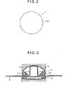
- Fig. 2 is a plan view of the decorative button 1.
- Fig. 3 is a cross section showing the decorative button 1 attached to the fabric 3.
- the decorative button 1 includes a base member 10 and a dome-shaped cap member 14 disposed on the base member 10, both members being made of brass, stainless steel, aluminum or the like and formed by drawing.
- the cap member 14 forms an outer surface (a convex and spherical surface) of the doom shape of the decorative button 1.
- the base member 10 includes a ring-shaped flange portion 12 and a cap-supporting portion 13.
- the flange portion 12 includes a prong-accommodating portion 11 for accommodating a prong portion 21 of the fixing member 2 when the fixing member 2 is attached to the fabric as shown in Fig. 3.
- the cap-supporting portion 13 is in the middle of the flange portion 12 i.e. on the inner periphery of the flange portion 12.
- the cap-supporting portion 13 projects from the lowest portion of the base member 10 toward the upper side thereof to abut to a middle portion of a rear surface of the cap member 14.
- the diameter of a bottom portion of the decorative button 1 is approximately 10 mm; the height thereof is approximately 4 mm; and the outside diameter of a top portion 13' of the cap-supporting portion 13 is approximately 3 mm.
- the diameter of the cap-supporting portion 13 of the decorative button 1 is set to be approximately constant from a base end portion of the cap-supporting portion 13 to the top portion 13' as well as to be maximum to the extent possible.
- the top portion 13', which abuts to an inner surface of the cap member 14, is not a point but a plane.
- the plane is not horizontal but slightly curved along the curving inner surface of the cap member 14. Accordingly, the cap-supporting portion 13 provides enhanced cap-supporting capacity.
- the fixing member 2 is a general cap prong.
- the fixing member 2 includes: a prong 20 including the prong portion 21; and a cap 22 to cover the prong 20. Owing to the cap 22 on a rear side of the fabric and the above-described dome-shaped cap member 14 on a front side of the fabric, the front and rear surfaces of the decorative button 1 do not give an untidy impression but have good and neat appearances.
- Figs. 4 and 5 each are an illustration for explaining a process of covering the base member 10 with the cap member 14.
- the cap member 14 Before attached to the base member 10, the cap member 14 has a cylindrical lower end portion 15 of the dome shape (the upper side in Figs. 4 and 5).
- the cylindrical lower end portion 15 is plastic-deformed by a pressing machine such that the lower end portion 15 holds the flange portion 12 of the base member 10.
- the pressing machine includes: a cap member mount 40 on the lower side, which has a recess 41 in an upper surface, the recess 41 being fittable with the dome shape of the cap member 14; a base member holder 42 on the upper side, which can be vertically moved by the base member holder 42 around the base member holder 42 with a projection 43 which serves such that the base member 10 is held by the cap-supporting portion 13; and a cylindrical press die 44 having a bending die portion 45 for bending the cylindrical lower end portion 15 of the cap portion 14.
- the cap member 14 When attaching the cap member 14 to the base member 10, the cap member 14 is placed upside down in the recess 41 of the cap member mount 40.
- the base member 10 is held by the base member holder 42 that is apart from the cap member mount 40 in the upward direction with the cap-supporting portion 13 accommodating the projection 43.
- the base member holder 42 is then lowered such that the base member 10 is brought in the cap member 14 and that the top portion 13' of the cap-supporting portion 13 reliably but gently abuts on the rear surface of the cap member 14.
- the press die 44 While maintaining the base member holder 42 in the state, the press die 44 is lowered (see Fig. 5).
- the cylindrical lower end portion 15 of the cap member 14 is bent by the bending die portion 45 toward the inner side of the radial direction so as to undetachably cover the flange portion 12 of the base member 10.
- the cap-supporting portion 13 supports the cap member 14 from the rear side of the cap member 14. Therefore, even when the cap member 14 receives an impact or the like from the outer side, the cap member 14 is not easily deformed by the impact.
Landscapes
- Slide Fasteners, Snap Fasteners, And Hook Fasteners (AREA)
Abstract
A decorative button (1) includes a base member (10) and a cap member (14). The base member (10) includes a prong-accommodating portion (11) that receives a prong portion (21) of a fixing member (2). The cap member (14) is disposed on the base member (10) and forms an outer surface of the decorative button (1). The base member (10) is provided with a cap-supporting portion (13) which abuts to a middle portion of a rear surface of the cap member (14) to support the cap member (14), thereby preventing a deformation of the cap member (14). A top portion (13') of the cap-supporting portion (13) is a plane to abut to the rear surface of the cap member (14) along the curving of the rear surface.
Description
- The present invention relates to a decorative button. Specifically, the invention relates to a dome-shaped decorative button.
- Dome-shaped decorative buttons are widely used for decoration of garments, shoes and bags, especially for decoration of leather and denim products due to an appearance of a head thereof like an embedded pin or rivet of a dome-like arched shape when the button is fixed to a fabric.
- One example of the dome-shaped buttons is disclosed in
JP-U-48-97104 - When the dome-shaped decorative button is a solid die cast product, the button becomes relatively heavy. Accordingly, especially when many buttons are used, reduction in total weight of the product may be hindered. Or a prong-accommodating portion for receiving a prong portion (a prong) of a fixing member may need to be provided after die cast molding by the way of curling a lower end portion of the molded product or by another way.
- The present invention has been attained in light of the above-described points. An object of the invention is to provide a decorative button including a cap which is not easily deformed.
- A decorative button according to an aspect of the invention is fixed to a fabric. The decorative button includes: a base member; and a cap member undetachably disposed on the base member, the cap member forming an outer surface of the decorative button. The base member abuts to a middle portion of a rear surface of the cap member to support the cap member. The base member includes a supporting portion which prevents a deformation of the cap member.
- In the decorative button according to the aspect of the invention, the supporting portion of the base member supports, from the rear side of the cap member, the middle portion of the cap member projecting in a dome-like shape. Accordingly, in attaching of the button to the fabric or when the button is in use, the risk of deforming the dome shape of the cap can be reduced even when a load or an impact is applied on the cap.
- In a decorative button of the invention, a fixing member thereof which fixes the decorative button to a fabric may preferably include a prong portion to penetrate the fabric. The base member may preferably include a flange portion which forms a prong-accommodating portion deforming and receiving the prong portion of the fixing member. The cap member may preferably include a lower end portion which holds the flange portion of the base member. According to the aspect, the prong portion of the fixing member penetrating the fabric is received in the prong-accommodating portion of the base member of the decorative button, thereby attaching the button to the fabric and engaging the button and the fixing member (see Fig. 3). For example, in another embodiment, a projection provided on the decorative button side along the axial direction may penetrate the fabric to be held on the fixing member side.
- In a decorative button according the invention, a top portion of the supporting portion of the base member curves along the rear surface of the cap member to make a plane-contact to the cap member. Specifically, the top portion of the supporting portion of the base member is adapted to make not a point-contact but a plane-contact to the rear surface of the cap member. The contacting surface of the supporting portion is not horizontal but curved along the rear surface of the curving cap. Accordingly, the cap-supporting capacity of the cap-supporting portion can be enhanced.
-
- Fig. 1 is a cross section showing a decorative button and a fixing member vertically facing to each other with a fabric therebetween;
- Fig. 2 is a plan view of the decorative button;
- Fig. 3 is a cross section showing the decorative button and the fixing member brought to each other from the state shown in Fig. 1 into engagement in which the decorative button and the fixing member are fixed to the fabric;
- Fig. 4 is a process illustration showing a state in which a base member is about to be covered by a cap member; and
- Fig. 5 is another process illustration showing a state in which the base member is covered by the cap member.
- A preferred embodiment of a decorative button according to the present invention will be described below with reference to the attached drawings. Fig. 1 is a cross section showing a
decorative button 1 and a fixing member (a cap prong) 2 vertically facing to each other with afabric 3 therebetween, thedecorative button 1 and thefixing member 2 to be fixed to thefabric 3. Fig. 2 is a plan view of thedecorative button 1. Fig. 3 is a cross section showing thedecorative button 1 attached to thefabric 3. - The
decorative button 1 includes abase member 10 and a dome-shaped cap member 14 disposed on thebase member 10, both members being made of brass, stainless steel, aluminum or the like and formed by drawing. Thecap member 14 forms an outer surface (a convex and spherical surface) of the doom shape of thedecorative button 1. Thebase member 10 includes a ring-shaped flange portion 12 and a cap-supportingportion 13. Theflange portion 12 includes a prong-accommodatingportion 11 for accommodating aprong portion 21 of thefixing member 2 when thefixing member 2 is attached to the fabric as shown in Fig. 3. The cap-supportingportion 13 is in the middle of theflange portion 12 i.e. on the inner periphery of theflange portion 12. The cap-supportingportion 13 projects from the lowest portion of thebase member 10 toward the upper side thereof to abut to a middle portion of a rear surface of thecap member 14. In the embodiment, the diameter of a bottom portion of thedecorative button 1 is approximately 10 mm; the height thereof is approximately 4 mm; and the outside diameter of a top portion 13' of the cap-supportingportion 13 is approximately 3 mm. - The diameter of the cap-supporting
portion 13 of thedecorative button 1 is set to be approximately constant from a base end portion of the cap-supportingportion 13 to the top portion 13' as well as to be maximum to the extent possible. The top portion 13', which abuts to an inner surface of thecap member 14, is not a point but a plane. The plane is not horizontal but slightly curved along the curving inner surface of thecap member 14. Accordingly, the cap-supportingportion 13 provides enhanced cap-supporting capacity. - The
fixing member 2 is a general cap prong. Thefixing member 2 includes: aprong 20 including theprong portion 21; and acap 22 to cover theprong 20. Owing to thecap 22 on a rear side of the fabric and the above-described dome-shaped cap member 14 on a front side of the fabric, the front and rear surfaces of thedecorative button 1 do not give an untidy impression but have good and neat appearances. - Figs. 4 and 5 each are an illustration for explaining a process of covering the
base member 10 with thecap member 14. Before attached to thebase member 10, thecap member 14 has a cylindricallower end portion 15 of the dome shape (the upper side in Figs. 4 and 5). The cylindricallower end portion 15 is plastic-deformed by a pressing machine such that thelower end portion 15 holds theflange portion 12 of thebase member 10. Specifically, the pressing machine includes: a cap member mount 40 on the lower side, which has a recess 41 in an upper surface, the recess 41 being fittable with the dome shape of thecap member 14; abase member holder 42 on the upper side, which can be vertically moved by thebase member holder 42 around thebase member holder 42 with aprojection 43 which serves such that thebase member 10 is held by the cap-supportingportion 13; and acylindrical press die 44 having abending die portion 45 for bending the cylindricallower end portion 15 of thecap portion 14. - When attaching the
cap member 14 to thebase member 10, thecap member 14 is placed upside down in the recess 41 of thecap member mount 40. Thebase member 10 is held by thebase member holder 42 that is apart from thecap member mount 40 in the upward direction with the cap-supportingportion 13 accommodating theprojection 43. Thebase member holder 42 is then lowered such that thebase member 10 is brought in thecap member 14 and that the top portion 13' of the cap-supportingportion 13 reliably but gently abuts on the rear surface of thecap member 14. While maintaining thebase member holder 42 in the state, the press die 44 is lowered (see Fig. 5). The cylindricallower end portion 15 of thecap member 14 is bent by thebending die portion 45 toward the inner side of the radial direction so as to undetachably cover theflange portion 12 of thebase member 10. - As described above, the cap-supporting
portion 13 supports thecap member 14 from the rear side of thecap member 14. Therefore, even when thecap member 14 receives an impact or the like from the outer side, thecap member 14 is not easily deformed by the impact.
Claims (3)
- A decorative button (1) fixed to a fabric (3), comprising:a base member (10);and a cap member (14) undetachably disposed on the base member (10), the cap member (14) forming an outer surface of the decorative button (1), whereinthe base member (10) abuts to a middle portion of a rear surface of the cap member (14) to support the cap member (14), andthe base member (10) includes a supporting portion (13) which prevents a deformation of the cap member (14).
- The decorative button (1) according to claim 1, wherein
the decorative button (1) is fixed to the fabric (3) by a fixing member (2) having a prong portion (21) penetrating the fabric (3),
the base member (10) includes a flange portion (12) which forms a prong-accommodating portion (11) deforming and receiving the prong portion (21) of the fixing member (2), and
the cap member (14) includes a lower end portion (15) which holds the flange portion (12) of the base member (10). - The decorative button (1) according to claim 1 or 2, wherein a top portion (13') of the supporting portion (13) of the base member (10) curves along the rear surface of the cap member (14) to make a plane-contact to the cap member (14).
Applications Claiming Priority (1)
| Application Number | Priority Date | Filing Date | Title |
|---|---|---|---|
| JP2006072925A JP2007244667A (en) | 2006-03-16 | 2006-03-16 | Decorative button |
Publications (1)
| Publication Number | Publication Date |
|---|---|
| EP1834538A1 true EP1834538A1 (en) | 2007-09-19 |
Family
ID=37801406
Family Applications (1)
| Application Number | Title | Priority Date | Filing Date |
|---|---|---|---|
| EP06024328A Withdrawn EP1834538A1 (en) | 2006-03-16 | 2006-11-23 | Decorative button |
Country Status (4)
| Country | Link |
|---|---|
| US (1) | US20070214612A1 (en) |
| EP (1) | EP1834538A1 (en) |
| JP (1) | JP2007244667A (en) |
| CN (1) | CN101036541A (en) |
Families Citing this family (5)
| Publication number | Priority date | Publication date | Assignee | Title |
|---|---|---|---|---|
| US7565721B2 (en) * | 2006-03-30 | 2009-07-28 | Ykk Corporation | Non-rotating sandwich button |
| JP5684796B2 (en) * | 2010-04-19 | 2015-03-18 | Ykk株式会社 | button |
| CN103298363A (en) * | 2011-01-13 | 2013-09-11 | Ykk株式会社 | Eyelet washer and eyelet-fastening method |
| KR101342053B1 (en) * | 2012-09-06 | 2013-12-18 | 허진호 | Accessory of personal daily goods |
| CN104661546B (en) * | 2012-09-28 | 2017-02-15 | Ykk株式会社 | Inspection component, inspection device, inspection method, and mounting device |
Citations (4)
| Publication number | Priority date | Publication date | Assignee | Title |
|---|---|---|---|---|
| US3577846A (en) * | 1969-06-30 | 1971-05-11 | United Carr Inc | Three-piece tack button |
| EP0174606A2 (en) * | 1984-09-13 | 1986-03-19 | Nippon Notion Kogyo Co., Ltd. | A button assembly for attachment to a garment fabric |
| DE8710108U1 (en) * | 1987-07-23 | 1987-09-17 | William Prym-Werke GmbH & Co KG, 5190 Stolberg | Anchoring link for connecting a haberdashery functional link, in particular a snap fastener part, to a carrier |
| DE3725439A1 (en) * | 1987-07-31 | 1989-02-09 | Prym Werke William | Anchoring member for connecting a functional haberdashery member, in particular a snap fastener part, to a backing |
Family Cites Families (9)
| Publication number | Priority date | Publication date | Assignee | Title |
|---|---|---|---|---|
| US310273A (en) * | 1885-01-06 | Mazstes hamburgeb | ||
| US2081196A (en) * | 1935-09-27 | 1937-05-25 | Emsig Max | Tack button |
| US2332578A (en) * | 1942-03-07 | 1943-10-26 | Waterbury Button Company | Composite metallic and nonmetallic button |
| AU557267B2 (en) * | 1983-04-13 | 1986-12-18 | Nippon Notion Kogyo Co. Ltd. | Button |
| US4700435A (en) * | 1986-10-06 | 1987-10-20 | Handy Button Machine Company | Tack button |
| JPH0748087Y2 (en) * | 1988-09-22 | 1995-11-08 | ワイケイケイ株式会社 | Stoppers for mounting buttons, etc. |
| ITPD940146A1 (en) * | 1994-08-05 | 1996-02-05 | Riccardo Candotti | BUTTON FOR PACKS |
| TW564694U (en) * | 2002-03-28 | 2003-12-01 | Universal Trim Supply Co Ltd | Safety surface buckle capable of preventing children from biting |
| US7565721B2 (en) * | 2006-03-30 | 2009-07-28 | Ykk Corporation | Non-rotating sandwich button |
-
2006
- 2006-03-16 JP JP2006072925A patent/JP2007244667A/en not_active Withdrawn
- 2006-11-23 EP EP06024328A patent/EP1834538A1/en not_active Withdrawn
-
2007
- 2007-01-04 CN CN200710002346.5A patent/CN101036541A/en active Pending
- 2007-02-20 US US11/708,255 patent/US20070214612A1/en not_active Abandoned
Patent Citations (4)
| Publication number | Priority date | Publication date | Assignee | Title |
|---|---|---|---|---|
| US3577846A (en) * | 1969-06-30 | 1971-05-11 | United Carr Inc | Three-piece tack button |
| EP0174606A2 (en) * | 1984-09-13 | 1986-03-19 | Nippon Notion Kogyo Co., Ltd. | A button assembly for attachment to a garment fabric |
| DE8710108U1 (en) * | 1987-07-23 | 1987-09-17 | William Prym-Werke GmbH & Co KG, 5190 Stolberg | Anchoring link for connecting a haberdashery functional link, in particular a snap fastener part, to a carrier |
| DE3725439A1 (en) * | 1987-07-31 | 1989-02-09 | Prym Werke William | Anchoring member for connecting a functional haberdashery member, in particular a snap fastener part, to a backing |
Also Published As
| Publication number | Publication date |
|---|---|
| JP2007244667A (en) | 2007-09-27 |
| CN101036541A (en) | 2007-09-19 |
| US20070214612A1 (en) | 2007-09-20 |
Similar Documents
| Publication | Publication Date | Title |
|---|---|---|
| US20070214612A1 (en) | Decorative button | |
| EP1477245A1 (en) | Successive forming device | |
| KR910013409A (en) | Method and apparatus for forming sheet metal blanks, especially for making cathode ray masks | |
| EP2514334A1 (en) | Button fastener and button structure | |
| WO2008018383A1 (en) | Button | |
| KR900008810Y1 (en) | Decorative button device | |
| JP5275476B2 (en) | Upper mold for button mounting | |
| CN103717101A (en) | Snap fastener-forming method, intermediate snap member, and snap fastener | |
| US20170265601A1 (en) | Male button for a snap button | |
| US7694394B2 (en) | Button | |
| EP0293758B1 (en) | Button collet and method and apparatus for making the same | |
| WO2013118262A1 (en) | Button attaching device and button holding die | |
| CN103298363A (en) | Eyelet washer and eyelet-fastening method | |
| JP2000500690A (en) | Cap rivet | |
| JPS637857B2 (en) | ||
| CN204444478U (en) | a snap button | |
| JP4401811B2 (en) | Decorative button | |
| US2072218A (en) | Novelty button | |
| JPH088641Y2 (en) | Button | |
| CN210747592U (en) | Novel metal button | |
| JP2001120317A (en) | Jewelry and its manufacturing method | |
| KR101865502B1 (en) | Logo indenting structure formed frying pan mold manufacture | |
| JP3137043U (en) | Decoration | |
| CN104661549A (en) | Method for affixing button and button | |
| JP2000317525A (en) | Press bending mold |
Legal Events
| Date | Code | Title | Description |
|---|---|---|---|
| PUAI | Public reference made under article 153(3) epc to a published international application that has entered the european phase |
Free format text: ORIGINAL CODE: 0009012 |
|
| 17P | Request for examination filed |
Effective date: 20061123 |
|
| AK | Designated contracting states |
Kind code of ref document: A1 Designated state(s): AT BE BG CH CY CZ DE DK EE ES FI FR GB GR HU IE IS IT LI LT LU LV MC NL PL PT RO SE SI SK TR |
|
| AX | Request for extension of the european patent |
Extension state: AL BA HR MK YU |
|
| AKX | Designation fees paid |
Designated state(s): DE FR IT |
|
| STAA | Information on the status of an ep patent application or granted ep patent |
Free format text: STATUS: THE APPLICATION IS DEEMED TO BE WITHDRAWN |
|
| 18D | Application deemed to be withdrawn |
Effective date: 20100531 |