EP1834063B2 - Threads with perturbations - Google Patents
Threads with perturbations Download PDFInfo
- Publication number
- EP1834063B2 EP1834063B2 EP05855438.7A EP05855438A EP1834063B2 EP 1834063 B2 EP1834063 B2 EP 1834063B2 EP 05855438 A EP05855438 A EP 05855438A EP 1834063 B2 EP1834063 B2 EP 1834063B2
- Authority
- EP
- European Patent Office
- Prior art keywords
- thread
- pin
- box
- lead
- flank
- Prior art date
- Legal status (The legal status is an assumption and is not a legal conclusion. Google has not performed a legal analysis and makes no representation as to the accuracy of the status listed.)
- Active
Links
- 230000013011 mating Effects 0.000 claims description 8
- 238000007789 sealing Methods 0.000 claims description 4
- 238000000034 method Methods 0.000 claims description 3
- 230000007423 decrease Effects 0.000 description 24
- 239000000314 lubricant Substances 0.000 description 10
- 239000000463 material Substances 0.000 description 10
- 238000004519 manufacturing process Methods 0.000 description 7
- 230000008901 benefit Effects 0.000 description 5
- 238000003754 machining Methods 0.000 description 5
- 230000008859 change Effects 0.000 description 4
- 230000000694 effects Effects 0.000 description 4
- 230000015572 biosynthetic process Effects 0.000 description 3
- 239000007789 gas Substances 0.000 description 3
- 239000002184 metal Substances 0.000 description 3
- 230000000737 periodic effect Effects 0.000 description 3
- 229910000975 Carbon steel Inorganic materials 0.000 description 2
- 239000010962 carbon steel Substances 0.000 description 2
- 238000005520 cutting process Methods 0.000 description 2
- 230000003247 decreasing effect Effects 0.000 description 2
- 238000009826 distribution Methods 0.000 description 2
- 239000012530 fluid Substances 0.000 description 2
- 230000004044 response Effects 0.000 description 2
- 229910000831 Steel Inorganic materials 0.000 description 1
- 229910045601 alloy Inorganic materials 0.000 description 1
- 239000000956 alloy Substances 0.000 description 1
- 230000007797 corrosion Effects 0.000 description 1
- 238000005260 corrosion Methods 0.000 description 1
- 230000001419 dependent effect Effects 0.000 description 1
- 238000005553 drilling Methods 0.000 description 1
- 238000009499 grossing Methods 0.000 description 1
- 230000006872 improvement Effects 0.000 description 1
- 239000007788 liquid Substances 0.000 description 1
- 238000005461 lubrication Methods 0.000 description 1
- 238000005498 polishing Methods 0.000 description 1
- 230000000630 rising effect Effects 0.000 description 1
- 239000010959 steel Substances 0.000 description 1
- 239000000126 substance Substances 0.000 description 1
Images


Classifications
-
- F—MECHANICAL ENGINEERING; LIGHTING; HEATING; WEAPONS; BLASTING
- F16—ENGINEERING ELEMENTS AND UNITS; GENERAL MEASURES FOR PRODUCING AND MAINTAINING EFFECTIVE FUNCTIONING OF MACHINES OR INSTALLATIONS; THERMAL INSULATION IN GENERAL
- F16L—PIPES; JOINTS OR FITTINGS FOR PIPES; SUPPORTS FOR PIPES, CABLES OR PROTECTIVE TUBING; MEANS FOR THERMAL INSULATION IN GENERAL
- F16L15/00—Screw-threaded joints; Forms of screw-threads for such joints
- F16L15/001—Screw-threaded joints; Forms of screw-threads for such joints with conical threads
- F16L15/004—Screw-threaded joints; Forms of screw-threads for such joints with conical threads with axial sealings having at least one plastically deformable sealing surface
-
- E—FIXED CONSTRUCTIONS
- E21—EARTH DRILLING; MINING
- E21B—EARTH DRILLING, e.g. DEEP DRILLING; OBTAINING OIL, GAS, WATER, SOLUBLE OR MELTABLE MATERIALS OR A SLURRY OF MINERALS FROM WELLS
- E21B17/00—Drilling rods or pipes; Flexible drill strings; Kellies; Drill collars; Sucker rods; Cables; Casings; Tubings
- E21B17/02—Couplings; joints
- E21B17/04—Couplings; joints between rod or the like and bit or between rod and rod or the like
- E21B17/042—Threaded
-
- F—MECHANICAL ENGINEERING; LIGHTING; HEATING; WEAPONS; BLASTING
- F16—ENGINEERING ELEMENTS AND UNITS; GENERAL MEASURES FOR PRODUCING AND MAINTAINING EFFECTIVE FUNCTIONING OF MACHINES OR INSTALLATIONS; THERMAL INSULATION IN GENERAL
- F16L—PIPES; JOINTS OR FITTINGS FOR PIPES; SUPPORTS FOR PIPES, CABLES OR PROTECTIVE TUBING; MEANS FOR THERMAL INSULATION IN GENERAL
- F16L15/00—Screw-threaded joints; Forms of screw-threads for such joints
- F16L15/001—Screw-threaded joints; Forms of screw-threads for such joints with conical threads
-
- F—MECHANICAL ENGINEERING; LIGHTING; HEATING; WEAPONS; BLASTING
- F16—ENGINEERING ELEMENTS AND UNITS; GENERAL MEASURES FOR PRODUCING AND MAINTAINING EFFECTIVE FUNCTIONING OF MACHINES OR INSTALLATIONS; THERMAL INSULATION IN GENERAL
- F16L—PIPES; JOINTS OR FITTINGS FOR PIPES; SUPPORTS FOR PIPES, CABLES OR PROTECTIVE TUBING; MEANS FOR THERMAL INSULATION IN GENERAL
- F16L15/00—Screw-threaded joints; Forms of screw-threads for such joints
- F16L15/06—Screw-threaded joints; Forms of screw-threads for such joints characterised by the shape of the screw-thread
-
- Y—GENERAL TAGGING OF NEW TECHNOLOGICAL DEVELOPMENTS; GENERAL TAGGING OF CROSS-SECTIONAL TECHNOLOGIES SPANNING OVER SEVERAL SECTIONS OF THE IPC; TECHNICAL SUBJECTS COVERED BY FORMER USPC CROSS-REFERENCE ART COLLECTIONS [XRACs] AND DIGESTS
- Y10—TECHNICAL SUBJECTS COVERED BY FORMER USPC
- Y10T—TECHNICAL SUBJECTS COVERED BY FORMER US CLASSIFICATION
- Y10T29/00—Metal working
- Y10T29/49—Method of mechanical manufacture
- Y10T29/49826—Assembling or joining
- Y10T29/49881—Assembling or joining of separate helix [e.g., screw thread]
Definitions
- Casing joints, liners, drill pipe, and drill collars are often used in drilling, completing, and producing a well.
- Casing joints may be emplaced in a wellbore to stabilize a formation, to protect a formation against elevated wellbore pressures (e.g., wellbore pressures that exceed a formation pressure), and the like.
- Casing joints may be coupled in an end-to-end manner by threaded connections, welded connections, and other connections known in the art. The connections may be designed so as to form a seal between an interior of the coupled casing joints and an annular space formed between exterior walls of the casing joints and walls of the wellbore.
- the seal may be, for example, an elastomeric seal (e.g., an o-ring seal), a metal-to-metal seal formed proximate the connection, or similar seals known in the art.
- seals are formed between the internal and external threads. Connections with this characteristic are said to have a "thread seal.”
- a "thread seal” means that a seal is formed between at least a portion of the internal thread on the box member and the external thread on the pin member.
- load flank designates the side wall surface of a thread that faces away from the outer end of the respective pin or box member on which the thread is formed and supports the weight (i.e., tensile load) of the lower tubular member hanging in the well bore.
- stab flank designates the side wall surface of the thread that faces toward the outer end of the respective pin or box member and supports forces compressing the joints toward each other such as the weight of the upper tubular member during the initial makeup of the joint or such as a force applied to push a lower tubular member against the bottom of a bore hole (i.e., compressive force).
- face of the box is the end of the box member facing outward from the box threads and the term “nose” of the pin is the end of the pin member facing outward from the threads of the connection. Upon makeup of a connection the nose of the pin is stabbed into and past the face of the box.
- wedge threads are characterized by threads that increase in width (i.e., axial distance between load flanks 225 and 226 and stab flanks 232 and 231) in opposite directions on the pin member 101 and box member 102. Wedge threads are extensively disclosed in U.S. Patent No. RE 30,647 issued to Blose , U.S. Pat. No. RE 34,467 issued to Reeves , U.S. Pat. No. 4,703,954 issued to Ortloff , and U.S. Pat. No. 5,454,605 issued to Mott , all assigned to the assignee of the present invention.
- the pin thread crest 222 is narrow towards the distal end of the pin member 101 while the box thread crest 291 is wide. Moving along the axis 105 (from right to left), the pin thread crest 222 widens while the box thread crest 291 narrows.
- thread seals are difficult to achieve with free-running threads having broad crests and roots, however, the same thread forms may have thread seals when used for wedge threads.
- Various thread forms may be used for embodiments of the invention disclosed below.
- One example of a suitable thread form is a semi-dovetailed thread form disclosed in U.S. Patent No. 5,360,239 issued to Klementich .
- Another thread form includes a multi-faceted load flank or stab flank, as disclosed in U.S. Patent No. 6,722,706 issued to Church .
- An open thread form with a generally rectangular shape is disclosed in U.S. Patent No. 6,578,880 issued to Watts .
- Each of the above thread forms are example thread forms that may be used for embodiments of the invention having wedge threads.
- a thread seal is accomplished by the contact pressure caused by interference over at least a portion of the connection between the pin load flank 226 and the box load flank 225 and between the pin stab flank 232 and the box stab flank 231, which occurs when the connection is made-up. Close proximity or interference between the roots 292 and 221 and crests 222 and 291 completes the thread seal when it occurs over at least a portion of where the flank interference occurs. Higher pressure may be contained with increased interference between the roots and crests ("root/crest interference") on the pin member 101 and the box member 102 and by increasing flank interference.
- This particular connection also includes a metal-to-metal seal that is accomplished by contact between corresponding sealing surfaces 103 and 104 locating on the pin member 101 and box member 102, respectively.
- make-up refers to threading a pin member and a box member together.
- selected make-up refers to threading the pin member and the box member together with a desired amount of torque, or based on a relative position (axial or circumferential) of the pin member with the box member.
- both the flank interference and root/crest interference increase as the connection is made-up (i.e. increase in torque increases flank interference and root/crest interference).
- the clearance decreases as the connection is made-up.
- corresponding flanks and corresponding roots and crests come closer to each other (i.e. clearance decreases or interference decreases) during make-up. Indeterminate make-up allows for the flank interference and root/crest interference to be increased by increasing the torque on the connection.
- a wedge thread may be able to thread seal higher pressures of gas and/or liquid by designing the connection to have more flank interference and/or root/crest interference or by increasing the torque on the connection, however, this also increases stress on the connection during make-up, which could lead to failure during use.
- Free-running threads used for oilfield tubular connections typically do not form thread seals when the connection is made-up.
- Figure 2 shows a prior art connection having free-running threads.
- the free-running threads include load flanks 154 and 155, stab flanks 157 and 158, crests 159 and 162, and roots 160 and 161.
- this connection relies on a positive stop torque shoulder formed by the contact of surfaces 151 and 152 disposed on the pin member 101 and the box member 102, respectively.
- the positive stop torque shoulder shown in Figure 2 is commonly referred to as a "pin nose shoulder.”
- the positive stop torque shoulder may instead be formed by the box face 163 and a mating shoulder (not shown) on the pin member 101.
- the positive stop torque shoulder also provides a seal. Unlike wedge threads, which make-up by the wedging of the pin thread and the box thread, free-running threads rely on the positive stop torque shoulder to load the connection during make-up.
- the pin member 101 and the box member 102 are screwed together until the surfaces 151 and 152 are brought into abutment, at which point the pin load flank 154 and box load flank 155 are also in abutment. Additional torque is applied to the pin member 101 and the box member 102 to load the surfaces 151 and 152 and the pin load flank 154 and box load flank 155 until the desired amount of make-up torque has been applied to the connection.
- connection shown in Figure 2 does not accomplish a thread seal because of the large gap 153 that exists between the pin stab flank 157 and box stab flank 158.
- the gap 153 occurs because of how free-running threads with positive stop torque shoulders are loaded. Applying torque to the connection during make-up against the positive stop torque shoulder causes the pin member 101 to be compressed while the box member 102 is stretched in tension. Note that when a box face shoulder is used, the box member 102 is compressed while the pin member 101 is stretched in tension. The force between the pin member 101 and the box member 102 is applied through the pin load flank 154 and box load flank 155. The pin stab flank 157 and the box stab flank 158 are not loaded during make-up.
- a wedge thread (as shown in Figure 1 ) is able to form a thread seal in part because of the interference between the load flanks 225 and 226 and the stab flanks 232 and 231. For wedge threads, this occurs near the end of the make-up of the connection because of the varying width of the pin thread and the box thread.
- the interference would exist substantially throughout the make-up of the connection because the pin thread and the box thread have a continuous width. Further, root/crest interference, if any, would exist substantially throughout the make-up of the connection. This could lead to galling of the threads and difficulty in making up the connection.
- the variance in thread width for a wedge thread occurs as a result of the load flanks having different leads than the stab flanks.
- a thread lead may be quantified in inches per revolution. Note that this is the inverse of a commonly used term "thread pitch,” which is commonly quantified as threads per inch.
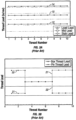
- a graph of the leads for a prior art wedge thread is shown in Figure 3A .
- the load lead 14 is constant over the length of the connection and greater than the stab lead 12, which is also constant.
- the nominal lead is shown as item 10.
- "nominal lead” refers to the average of the load lead 14 and the stab lead 12. The thread will widen with each revolution by the difference in the load lead 14 and the stab lead 12.
- the difference in the load lead 14 and the stab lead 12 is sometimes referred to as the "wedge ratio.”
- the load lead 14 and the stab lead 12 would be substantially equal causing the free-running thread to have a substantially constant thread width (i.e. a zero wedge ratio).
- a thread is cut on a tubular using a substantially constant thread lead (including the load lead and the stab lead), however, some variance in the thread lead occurs during the manufacturing process, which is typically includes machining with a mill or lathe.
- the variance in the thread lead manifests as a slight periodic variation in the thread lead above and below the intended value for the thread lead. This phenomenon is commonly referred to as "thread drunkenness.”
- the amount of thread drunkenness that occurs is largely dependent on the machine being used. It may be caused by slop or backlash in the machine tool that is cutting the thread.
- the material being machined and the dimensions of the part being machined are also variables that affect the amount of thread drunkenness.
- Thread drunkenness can also occur as a result of the electronic controls "hunting" the location for the machine tool.
- thread drunkenness is on the order of 0,00127 mm (0.00005 inch) to 0,012.7mm (0.0005 inch) from nominal and is not visible to the eye.
- the period of the thread drunkenness is typically at least once per thread turn. Greater than normal thread drunkenness is visible as "chatter on the thread surface and may result in the connection being scrapped.
- manufacturers try to eliminate any variations from nominal, such as experienced with thread drunkenness.
- the pin thread lead 21 and box thread lead 22 are substantially equal. Then, at the other end of the connection, the box thread lead 22 is larger than the pin thread lead 21.
- the changes in the pin thread lead 21 and box thread lead 22 are step changes (i.e. substantially instantaneous changes in the lead).
- the varied thread leads disclosed by Dearden are intended to distribute loading across a greater portion of the connection, and have no effect on the inability of the free-running threads to form a thread seal. Dearden does not disclose varying a load lead or stab lead independent of each other.
- connection is disclosed in U.S. Application Serial No. 10/126,918 entitled “Threaded Connection Especially for Radially Plastically Expandable Conduit,” (“Sivley) and assigned to the assignee of the present invention. That application is incorporated herein by reference in its entirety.
- Sivley discloses connections having a variance in load lead and/or stab lead on one or both of the pin member and the box member.
- a graph of an embodiment disclosed by Sivley is shown in Figure 3C .
- Sivley discloses varying the load lead 14 relative to the stab lead 12 at a selected rate over at least a portion of the pin thread and/or box thread.
- the connection is a wedge thread as shown by the difference between the load lead 14 and the stab lead 12.
- the load lead 14 and the stab lead 12 converge at a linear rate towards the end of the thread.
- Sivley discloses various other embodiments having load leads 14 and stab leads 12 that vary at linear rates relative to each other. The variance in the thread leads distributes the loads experienced by the connection over the length of the connection.
- free-running threads suitable for oilfield tubulars fail to provide thread seals suitable for the pressure differentials experienced by the tubulars in the downhole environment.
- Wedge threads provide thread seals, but have difficulty sealing gases, which are more difficult to seal than fluids. Also, any improvement in the thread seal is generally desirable. What is still needed is an improved thread seal for wedge threads.
- the present invention relates to a threaded connection according to claim 1.
- Document US4917409 discloses a threaded connection to connect pipes in a continuous flow conduit forming relationship.
- the threaded connection employs a tapered or wedge shaped thread with angled or tapered thread load flanks to obtain superior mechanical strength by controlling stress levels in the connection.
- the dimension of the thread structure in the root and crests dimensions is chosen to prevent trapping of thread lubricant during rotational make-up which may produce false torque make-up values.
- the present invention relates to a method of forming a thread seal on a connection in accordance with claim 6.
- the present invention relates to threads for tubulars. More specifically, the present invention relates to wedge threads having increased contact pressure between portions of the pin thread and the box thread.
- a thread lead refers generally to the group of leads consisting of the load lead, the stab lead, and the nominal lead.
- perturbation refers to a deviation in an original path of the load flank, the stab flank, the root, or the crest on the thread such that a bump is formed thereon. After the perturbation, the path returns at least partially towards the original path prior to the perturbation.
- helical length refers to the number of turns of the thread that the contactor is disposed, and may be expressed in the number of degrees about the axis of the tubular (i.e. 360 degrees is one thread pitch).
- Embodiments of the present invention have variations in at least one thread lead over at least a portion of a thread such that contact pressure between mating load flanks and/or mating stab flanks varies. Some embodiments may also vary the height of a thread (as measured from root to crest) in order to form a thread seal. Increases in contact pressure increases the maximum sealing pressure that may be achieved by the thread seal at the location of the perturbation. Decreases in contact pressure may be used to provide locations for an increased amount of thread lubricant to remain between the pin thread and the box thread after make-up of the connection.
- Figure 4A a graph of thread leads versus axial position in accordance with one embodiment of the present invention is shown.
- Figure 4B shows an unwrapped wedge thread corresponding to the graph in Figure 4A .
- the graph in Figure 4A shows the box load lead 14B and box stab lead 12B relative to pin load lead 14A and pin stab lead 12A.
- the pin thread has a substantially constant load lead 14A and stab lead 12A over the illustrated portion, while the box thread has perturbations caused by variances in the load lead 14B and stab lead 12B.
- the perturbations may instead be located on the pin thread.
- a perturbation of the box thread begins at points A1 and A2 where the box load lead 14B decreases and the box stab lead 12B increases.
- the corresponding change in the shape of the thread is shown in Figure 4B .
- the box load flank 226 and box stab flank 231 begin to "pinch" the pin thread.
- the box load lead 14B and the box stab lead 12B return to the original values. This continues for a selected helical length resulting in a portion of the box thread and pin thread at which increased contact pressure exists when the connection is made-up.
- the box load lead 14B increases and the box stab lead 12B decreases.
- the box load flank 226 and the box stab flank 231 substantially return to the original path prior to the start of the perturbation.
- one or both of the box load flank 226 and the box stab flank 231 may not return fully to the original path.
- the maximum value and the minimum value in thread lead changes may not be equal in magnitude. For example, a thread lead may increase by "x" over the original thread lead for a helical length "L.” To return to the original path, the same thread lead may decrease by 1/2*x under the original thread lead for a helical length 2L.
- the perturbation may have a helical length that is less than about 360 degrees. In another embodiment, the perturbation may have a helical length that is less than about 180 degrees.
- Figures 4A and 4B provide an exaggerated example of a thread perturbation for illustrative purposes.
- the wedge thread in Figure 4B is partially made-up such that the only point of contact between the load flanks 225 and 226 and the stab flanks 231 and 232 is at the perturbation between points B1, B2 and points C1, C2.
- the gap between the load flanks 225 and 226 and the stab flanks 231 and 232 is exaggerated to be visible in Figure 4B .
- the change in the thread lead and the helical length which it continues may be selected such that the perturbation is between about 0,0127 mm (0.0005 inch) and about 0,127 mm (0.005 inch) in size.
- the perturbation may be between about 0,0254 mm (0.001 inch) and about 0,0508 mm (0.002 inch) in size.
- the gap between the load flanks 225 and 226 and the stab flanks 231 and 232 will disappear as the contact pressure at the perturbations locally deforms the thread.
- greater contact pressure will exist between the load flanks 225 and 226 and the stab flanks 231 and 232 at the perturbations in Figure 4B between points A1, A2 and points D1, D2 than the remaining portions of the threads.
- the helical length of each perturbation may vary as desired, however, the manufacturing method may limit the variability of the helical length.
- CNC computer numerically controlled
- CNC machines may be controlled by CNC programs.
- the CNC program consists of positions for each axis of control. For example, if the CNC lathe has an axial position and a rotational position, the program would have an axial position value corresponding with each rotational position. Because a CNC lathe is usually rotating at a set speed measured in rotations per minute (“RPM”), the CNC program typically has the rotational positions in order and at set increments as the part is rotated in the machine.
- RPM rotations per minute
- the increments at which the rotational positions are spaced is commonly referred to as the "resolution" of the lathe. For example, if the resolution is about 90 degrees, a data point will exist for each sequential increment of about 90 degrees. An axial position would be selected for each increment. Typically, the CNC lathe will move the axial position at a substantially constant speed between points. The speed is selected as required to reach the next axial position at substantially the same time as the corresponding rotational position.
- the thread lead can be selected by calculating the value for the increments such that for each revolution, the axial position advances by a distance substantially equal to the thread lead. For example, a lead of 25,4 mm (1 inch) per revolution would advance by a 6,35 mm (1/4 inch) every 90 degrees.
- a CNC mill having 4 axes of control (X, Y, Z, and rotational) may be used.
- the resolution of the machine used may limit the minimum helical length of a perturbation.
- the minimum perturbation would be about 180 degrees (90 degrees of increased lead, 90 degrees of decreased lead). If the maximum contact pressure is desired over an extended length (similar to Figures 4A and 4B ), then the minimum helical length of the perturbation would be about 270 degrees (90 degrees increased lead, 90 degrees at original lead, 90 degrees at decreased lead). Higher resolution (i.e. smaller rotational increments) allows for greater variability in the helical length of the perturbation.
- machines with higher or lower resolution may be used to form the perturbations without departing from the scope of the present invention.
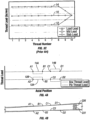
- Figure 5A shows a graph of a pin load lead 14A relative to axial position in accordance with one embodiment of the present invention.
- Figure 5B shows the idealized shape of the perturbation corresponding to the graph in Figure 5A
- Figure 5C shows what may be the actual shape of the perturbation as a result of the machine used.
- the pin load lead 14A increases by a selected amount at point A to achieve increased contact pressure between the pin load flank 225 and the box load flank 226. Then, the pin load lead 14A returns to the original pin load lead 14A at point B.
- the pin load lead 14A decreases by about the same amount as the previous increase to return the pin load flank 225 to about its original path at point D.
- the pin load flank 225 corresponding to the graph of the pin load lead 14A in Figure 5A would be substantially as shown in Figure 5B .
- the pin load flank 225 changes instantaneously at point A and at a constant linear slope (about equal to the change in pin load lead 14A shown in Figure 5A ) until point B.
- the pin load flank 225 begins to return to its original path until point D.
- Momentum of the moving parts and response time in the controls may result in a more smoothed out perturbation as shown in Figure 5C .
- the curvature may be substantially sinusoidal. Although the precise shape of the perturbation may vary by production method, the benefits of the increased contact pressure may still be realized.
- a perturbation may be formed during the finishing pass ("skim cut") of the thread.
- a skim cut refers to a cut on a thread subsequent to a first cut.
- a skim cut removes 0,508 mm (0.020 inches) or less of material. Because less material is removed during the skim cut, higher machining tolerances for the size of the perturbation may be achieved. It should be noted, however, that the machined perturbation may be smaller in size than what was coded into the CNC program. This is largely due to push-off of the machine tool from the thread while cutting.
- FIG. 6A a graph of a box load lead 14B relative to axial position is shown in accordance with one embodiment of the present invention.
- Figure 6B shows the corresponding box load flank 226.
- the shape of the perturbation is slightly curved as a result of the machine used to form the thread.
- the box load lead 14B decreases at point A. Note that this is the inverse of Figure 5A , which changed the pin load lead 14A to form the perturbation.
- Viewing Figures 5A and 6A relative to each other shows that either the pin thread or box thread may have a perturbation to achieve and increased contact pressure at a selected location on the threads.
- the change in stab leads 12A and 12B is the inverse of the load leads 14A and 14B.
- the pin load lead 14A may increase and the pin stab lead 12A may decrease at about the same axial position.
- the pin thread would widen causing increased contact pressure between the neighboring box thread.
- the box load lead 14B may decrease and the box stab lead 12 may decrease as shown in Figure 4A .
- Figures 7A and 7B a perturbation in accordance with one embodiment of the present invention is shown.
- Figure 7A shows a graph of the pin load lead 14A
- Figure 7B shows the corresponding perturbation on the pin load flank 225.
- the pin load lead 14A increases at point A by a selected amount.
- the pin load lead 14A decreases by about the same selected amount below the original pin load lead 14A.
- the perturbation ends at point C where the pin load flank 225 returns to about its original path.
- the corresponding perturbation shown in Figure 7B resembles a rounded bump.
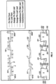
- Figure 8 multiple perturbations in accordance with one embodiment of the present invention are shown.
- Figure 8 includes a graph the pin load lead 14A and the pin stab lead 12A.
- the embodiment shown in Figure 8 may be referred to as "induced thread drunkenness" because it resembles the wobbling effect of machining as discussed above. Thread drunkenness may be "induced” by programming thread lead changes into the CNC program.
- the induced thread drunkenness begins at points 801A and 801B where both the pin load lead 14A (termed as “instantaneous pin load lead” in this embodiment) and the pin stab lead 12A (termed as “instantaneous box load lead” in this embodiment) begin to vary upward and downward, which results in a rippled pin load flank 225 and pin stab flank 232.
- the initial increase in pin load lead 14A and pin stab lead 12A may have a helical length of L
- the subsequent decrease in pin load lead 14A and pin stab lead 12A may have a helical length of 2L such that the pin load flank 225 and pin stab flank 232 cross their original paths.
- the total increases in pin load lead 14A and pin stab lead 12A multiplied by the helical lengths of the heightened thread leads should substantially equal the total decreases in pin load lead 14A and pin stab lead 12A multiplied by the helical lengths.
- the pin load lead 14A and pin stab lead 12A are less than the average pin load lead 810 and the average pin stab lead 811, respectively, for a total of 5L in helical length.
- the pin load flank 225 and pin stab flank 232 return to their original paths at points 802A and 802B after the pin load lead 14A and pin stab lead 12A have been above the average pin load lead 810 and the average pin stab lead 811, respectively, for a total of 5L in helical length.
- the helical lengths may not need to be equivalent if at any point the absolute values of decreases or increases in the pin load lead 14A and pin stab lead 12A are not equal.
- increases in the pin load lead 14A may be about 0,0508 mm (0.002 inch) per revolution above the average pin load lead 810, and decreases in the pin load lead 14A may be about 0,0254 mm (0.001 inch) per revolution below the average pin load lead 810.
- the helical length of decreases in the pin load lead 14A may be about twice as much as the helical length of increases in the pin load lead 14A to return to the original path of the pin load flank 225.
- some embodiments of the present invention may vary asymmetrically from nominal.
- the increases and decreases in the thread leads, as well as their respective helical lengths may vary without departing from the scope of the present invention. Further, embodiments of the present invention may have perturbations that do not fully return to their original paths.
- cross sections of threads corresponding to the graph are shown.
- the cross sections are labeled A, B, and C, which corresponds to points A, B, and C on the graph.
- the wedge thread in Figure 4B is partially made-up such that the only point of contact between the load flanks 225 and 226 and the stab flanks 231 and 232 is at the perturbations.
- the positive and negative perturbations are equal in absolute value such that contact occurs at each maximum and minimum of the perturbations at substantially the same make-up position.
- This contact is shown in cross sections A and C, which are at a local minimum and local maximum, respectively. At the local minimums of the perturbations (cross section A), the stab flanks 231 and 232 are in contact.
- the load flanks 225 and 226 are in contact.
- the gaps between the load flanks 225 and 226 and the stab flanks 231 and 232 may be substantially equal, which is shown in cross section B.
- Figure 9 includes a graph the pin load lead 14A and the pin stab lead 12A.
- the embodiment shown in Figure 9 is similar to the "induced thread drunkenness" shown in Figure 8 , except that the pin load lead 14A and the pin stab lead 12A do not increase and decrease in unison. Instead, the pin load lead 14A and the pin stab lead 12A increase and decrease at opposing locations such that the pin thread widens and narrows with each of the perturbations.
- the pin load lead 14A is greater than the average load lead 810 at substantially the same locations where the pin stab lead 12A is less than the average stab lead 811.
- Embodiments of the present invention may also have variable thread heights (i.e. perturbations on a root and/or a crest) on the pin member and/or the box member.
- the embodiment shown in Figure 9 includes a variance in the pin thread height.
- the pin thread height increases at about the same locations as increases in the pin thread width causing interference between the box thread root 221 and the pin thread crease 222, as shown in cross section A when compared to cross section B.
- perturbations on either the pin member or the box member may be on portions of the thread that would not contact each other (i.e. at sufficiently different axial positions such that the perturbations do not interact).
- the desired amount of contact pressure created by perturbations may vary based on the pressure to be sealed, the substance to be sealed, and the material used for the connection. As discussed above, a higher contact pressure results in the ability to seal a greater pressure. Further, if gas, which is more difficult to seal than fluid, is to be sealed by the connection, a greater contact pressure may be desired.
- the material to be used for the connection may limit the maximum allowable contact pressure. For example, a corrosion resistant alloy (CRA) is typically more susceptible to damage from localized stress (such as that resulting from perturbations) than other high strength steels.
- CRA corrosion resistant alloy
- Those having ordinary skill in the art will be able to select the desired contact pressure in view of the material to be used for the connection. Alternatively, the material may be selected in view of the desired contact pressure.
- Embodiments of the present invention may include one or more stress relief grooves in the roots of the pin thread and/or the box thread.
- stress relief grooves are taught in U.S. Patent No. 6,050,610 issued to Enderle et al. , and assigned to the assignee of the present invention.
- Enderle discloses stress relief grooves that provide an escape for trapped lubricant during make-up of the connection. Trapped lubricant may result in false torque readings, which can result in improperly made-up connections. Further, trapped lubricant may damage the connection during make-up if pressure build up within the connection occurs. This problem typically occurs in colder environments when the lubricant is more viscous and less able to escape from the connection to relieve pressure build up. It may also be exacerbated if the connection is made-up with a high speed of rotation.
- stress relief grooves in the roots of the pin thread and/or the box thread, which act as a pressure release, are that the stress relief grooves reduce the ability to thread seal on portions of the threads having the thread seal. Because, as disclosed by Enderle, the stress relief groove may be employed over a limited portion of the thread and in any shape, or of varying depths, the remaining portion of the thread can be used to form an internal and external pressure seal (e.g. by forming one or more perturbations on the thread). In such an embodiment, a thread seal would exist where one or more perturbations are appropriately located away from any stress relief groove.
- the perturbations shown in Figures 8 and 9 may be used instead of the stress relief grooves disclosed by Enderle.
- Periodic or induced thread drunkenness as shown in Figures 8 and 9 results in small, spaced apart pockets of reduced contact pressure or gaps along the threads.
- the stress relief grooves disclosed by Enderle largely function by providing an exit for excess thread dope.
- the spaced apart pockets can provide places for the lubricant to collect in the connection rather than exit the connection.
- the present inventor believes that the intermittent trapping of the lubricant between perturbations with increased contact pressure can provide an improved thread seal. Further, having trapped lubricant ensures that sufficient lubrication exists in the connection to aid in disconnecting the tubulars after use.
- the size of the perturbations may be selected to be about twice (i.e. +/- 0.002 inch) the size of the natural variations.
- Characteristics of the connection may affect the desired size of the perturbations.
- a metal-to-metal seal e.g. a thread seal
- the surfaces coming into contact rub for a short distance causing "burnishing" of the surfaces.
- burnishing means a slight polishing or smoothing of the surfaces. If the surfaces contact for too great of a length at too great of a contact pressure, galling may occur. Galling occurs when the lubricant is displaced from between the surfaces as sliding contact continues, resulting in an increase in friction and heat build up. To avoid undesirable galling, perturbations should be sized to prevent extended lengths of sliding contact during make-up.
- contact pressure between mating surfaces e.g.
- load flanks, stab flanks, and roots and crests is typically from about 25 percent to about 100 percent of the yield strength of the material.
- Closed thread forms e.g. dovetailed threads
- a thread seal is formed by surfaces coming together over a short distance with sharply rising contact pressure ending with the contact pressure within the effect range of forming a thread seal.
- the wedge ratio of a wedge thread is a parameter that may affect the desired size of the perturbation. Essentially, the wedge ratio determines how "quickly" (i.e. over how many linear inches the surfaces contact during make-up) the surfaces come into contact. In general, larger wedge ratios allow for larger perturbations than smaller wedge ratios.
- the size of the perturbation may be selected to be between about 0.1 and about 0.2 times the wedge ratio. For example if the wedge ratio (difference between the load lead and the stab lead) is about 0,508 mm (0.002 inch) inches), the desired size of the perturbation would be between about 0,0508 mm (0.002 inch) and about 0,102 mm (0.004 inch).
- CRA is more prone to galling than carbon steel.
- a connection made of CRA would be more likely to have thread galling than a connection made of carbon steel having the same size perturbation.
- the connection made of CRA may have a smaller perturbation.
Description
- Casing joints, liners, drill pipe, and drill collars (collectively referred to as "tubulars") are often used in drilling, completing, and producing a well. Casing joints, for example, may be emplaced in a wellbore to stabilize a formation, to protect a formation against elevated wellbore pressures (e.g., wellbore pressures that exceed a formation pressure), and the like. Casing joints may be coupled in an end-to-end manner by threaded connections, welded connections, and other connections known in the art. The connections may be designed so as to form a seal between an interior of the coupled casing joints and an annular space formed between exterior walls of the casing joints and walls of the wellbore. The seal may be, for example, an elastomeric seal (e.g., an o-ring seal), a metal-to-metal seal formed proximate the connection, or similar seals known in the art. In some connections, seals are formed between the internal and external threads. Connections with this characteristic are said to have a "thread seal." As used herein, a "thread seal" means that a seal is formed between at least a portion of the internal thread on the box member and the external thread on the pin member.
- It will be understood that certain terms are used herein as they would be conventionally understood where tubular joints are being connected in a vertical position along a central axis of the tubular members such as when making up a pipe string for lowering into a well bore. Thus, the term "load flank" designates the side wall surface of a thread that faces away from the outer end of the respective pin or box member on which the thread is formed and supports the weight (i.e., tensile load) of the lower tubular member hanging in the well bore. The term "stab flank" designates the side wall surface of the thread that faces toward the outer end of the respective pin or box member and supports forces compressing the joints toward each other such as the weight of the upper tubular member during the initial makeup of the joint or such as a force applied to push a lower tubular member against the bottom of a bore hole (i.e., compressive force). The term "face" of the box is the end of the box member facing outward from the box threads and the term "nose" of the pin is the end of the pin member facing outward from the threads of the connection. Upon makeup of a connection the nose of the pin is stabbed into and past the face of the box.
- One type of thread commonly used to form a thread seal is a wedge thread. In
Figure 1 , a connection having a wedge thread is shown. "Wedge threads" are characterized by threads that increase in width (i.e., axial distance betweenload flanks stab flanks 232 and 231) in opposite directions on thepin member 101 andbox member 102. Wedge threads are extensively disclosed inU.S. Patent No. RE 30,647 issued to Blose ,U.S. Pat. No. RE 34,467 issued to Reeves ,U.S. Pat. No. 4,703,954 issued to Ortloff , andU.S. Pat. No. 5,454,605 issued to Mott , all assigned to the assignee of the present invention. On thepin member 101, thepin thread crest 222 is narrow towards the distal end of thepin member 101 while thebox thread crest 291 is wide. Moving along the axis 105 (from right to left), the pin thread crest 222 widens while the box thread crest 291 narrows. - Generally, thread seals are difficult to achieve with free-running threads having broad crests and roots, however, the same thread forms may have thread seals when used for wedge threads. Various thread forms may be used for embodiments of the invention disclosed below. One example of a suitable thread form is a semi-dovetailed thread form disclosed in
U.S. Patent No. 5,360,239 issued to Klementich . Another thread form includes a multi-faceted load flank or stab flank, as disclosed inU.S. Patent No. 6,722,706 issued to Church . An open thread form with a generally rectangular shape is disclosed inU.S. Patent No. 6,578,880 issued to Watts . Each of the above thread forms are example thread forms that may be used for embodiments of the invention having wedge threads. Those having ordinary skill in the art will appreciate that the teachings contained herein are not limited to particular thread forms. - For wedge threads, a thread seal is accomplished by the contact pressure caused by interference over at least a portion of the connection between the
pin load flank 226 and thebox load flank 225 and between thepin stab flank 232 and thebox stab flank 231, which occurs when the connection is made-up. Close proximity or interference between theroots crests pin member 101 and thebox member 102 and by increasing flank interference. This particular connection also includes a metal-to-metal seal that is accomplished by contact betweencorresponding sealing surfaces pin member 101 andbox member 102, respectively. - A property of wedge threads, which typically do not have a positive stop torque shoulder on the connection, is that the make-up is "indeterminate," and, as a result, the relative position of the pin member and box member varies more for a given torque range to be applied than connections having a positive stop torque shoulder. As used herein, "make-up" refers to threading a pin member and a box member together. "Selected make-up refers to threading the pin member and the box member together with a desired amount of torque, or based on a relative position (axial or circumferential) of the pin member with the box member. For wedge threads that are designed to have both flank interference and root/crest interference at a selected make-up, both the flank interference and root/crest interference increase as the connection is made-up (i.e. increase in torque increases flank interference and root/crest interference). For wedge threads that are designed to have root/crest clearance, the clearance decreases as the connection is made-up. Regardless of the design of the wedge thread, corresponding flanks and corresponding roots and crests come closer to each other (i.e. clearance decreases or interference decreases) during make-up. Indeterminate make-up allows for the flank interference and root/crest interference to be increased by increasing the torque on the connection. Thus, a wedge thread may be able to thread seal higher pressures of gas and/or liquid by designing the connection to have more flank interference and/or root/crest interference or by increasing the torque on the connection, however, this also increases stress on the connection during make-up, which could lead to failure during use.
- Free-running threads used for oilfield tubular connections typically do not form thread seals when the connection is made-up.
Figure 2 shows a prior art connection having free-running threads. The free-running threads includeload flanks stab flanks crests roots surfaces pin member 101 and thebox member 102, respectively. The positive stop torque shoulder shown inFigure 2 is commonly referred to as a "pin nose shoulder." In other connections, the positive stop torque shoulder may instead be formed by thebox face 163 and a mating shoulder (not shown) on thepin member 101. The positive stop torque shoulder also provides a seal. Unlike wedge threads, which make-up by the wedging of the pin thread and the box thread, free-running threads rely on the positive stop torque shoulder to load the connection during make-up. To make-up the connection shown inFigure 2 , thepin member 101 and thebox member 102 are screwed together until thesurfaces pin load flank 154 andbox load flank 155 are also in abutment. Additional torque is applied to thepin member 101 and thebox member 102 to load thesurfaces pin load flank 154 andbox load flank 155 until the desired amount of make-up torque has been applied to the connection. - The connection shown in
Figure 2 does not accomplish a thread seal because of thelarge gap 153 that exists between thepin stab flank 157 andbox stab flank 158. Thegap 153 occurs because of how free-running threads with positive stop torque shoulders are loaded. Applying torque to the connection during make-up against the positive stop torque shoulder causes thepin member 101 to be compressed while thebox member 102 is stretched in tension. Note that when a box face shoulder is used, thebox member 102 is compressed while thepin member 101 is stretched in tension. The force between thepin member 101 and thebox member 102 is applied through thepin load flank 154 andbox load flank 155. Thepin stab flank 157 and thebox stab flank 158 are not loaded during make-up. This results in contact pressure between theload flanks stab flanks Figure 1 ) is able to form a thread seal in part because of the interference between theload flanks stab flanks load flanks stab flanks - The variance in thread width for a wedge thread occurs as a result of the load flanks having different leads than the stab flanks. A thread lead may be quantified in inches per revolution. Note that this is the inverse of a commonly used term "thread pitch," which is commonly quantified as threads per inch. A graph of the leads for a prior art wedge thread is shown in
Figure 3A . For this connection, theload lead 14 is constant over the length of the connection and greater than thestab lead 12, which is also constant. The nominal lead is shown asitem 10. As used herein, "nominal lead" refers to the average of theload lead 14 and thestab lead 12. The thread will widen with each revolution by the difference in theload lead 14 and thestab lead 12. The difference in theload lead 14 and thestab lead 12 is sometimes referred to as the "wedge ratio." For a free-running thread (i.e. nonwedge thead), theload lead 14 and thestab lead 12 would be substantially equal causing the free-running thread to have a substantially constant thread width (i.e. a zero wedge ratio). - Generally, a thread is cut on a tubular using a substantially constant thread lead (including the load lead and the stab lead), however, some variance in the thread lead occurs during the manufacturing process, which is typically includes machining with a mill or lathe. During machining, the variance in the thread lead manifests as a slight periodic variation in the thread lead above and below the intended value for the thread lead. This phenomenon is commonly referred to as "thread drunkenness." The amount of thread drunkenness that occurs is largely dependent on the machine being used. It may be caused by slop or backlash in the machine tool that is cutting the thread. The material being machined and the dimensions of the part being machined are also variables that affect the amount of thread drunkenness. Thread drunkenness can also occur as a result of the electronic controls "hunting" the location for the machine tool. Typically, thread drunkenness is on the order of 0,00127 mm (0.00005 inch) to 0,012.7mm (0.0005 inch) from nominal and is not visible to the eye. The period of the thread drunkenness is typically at least once per thread turn. Greater than normal thread drunkenness is visible as "chatter on the thread surface and may result in the connection being scrapped. Generally, manufacturers try to eliminate any variations from nominal, such as experienced with thread drunkenness.
- Intentional variances in thread leads have been disclosed in the prior art for the purposes of load distribution, however, the present inventor is unaware of variances in thread leads to form a thread seal for a wedge thread or a free-running thread. One example of a varied thread lead for stress distribution is disclosed in
U.S. Patent No. 4,582,348 issued to Dearden, et al. Dearden discloses a connection with free-running threads that has the pin thread and box thread divided into three portions with different leads (note that Dearden refers to thread pitch, which is quantified as threads per inch). InFigure 3B , a graph of the thread leads for the box member and the pin member is shown. As shown in the graph, at one end of the connection, thepin thread lead 21 is larger than thebox thread lead 22. In the intermediate portion 23, thepin thread lead 21 andbox thread lead 22 are substantially equal. Then, at the other end of the connection, thebox thread lead 22 is larger than thepin thread lead 21. In Dearden, the changes in thepin thread lead 21 andbox thread lead 22 are step changes (i.e. substantially instantaneous changes in the lead). The varied thread leads disclosed by Dearden are intended to distribute loading across a greater portion of the connection, and have no effect on the inability of the free-running threads to form a thread seal. Dearden does not disclose varying a load lead or stab lead independent of each other. - Another connection is disclosed in
U.S. Application Serial No. 10/126,918 entitled "Threaded Connection Especially for Radially Plastically Expandable Conduit," ("Sivley) and assigned to the assignee of the present invention. That application is incorporated herein by reference in its entirety. Sivley discloses connections having a variance in load lead and/or stab lead on one or both of the pin member and the box member. A graph of an embodiment disclosed by Sivley is shown inFigure 3C . Sivley discloses varying theload lead 14 relative to thestab lead 12 at a selected rate over at least a portion of the pin thread and/or box thread. InFigure 3C , the connection is a wedge thread as shown by the difference between theload lead 14 and thestab lead 12. Theload lead 14 and thestab lead 12 converge at a linear rate towards the end of the thread. Sivley discloses various other embodiments having load leads 14 and stab leads 12 that vary at linear rates relative to each other. The variance in the thread leads distributes the loads experienced by the connection over the length of the connection. - In the prior art, free-running threads suitable for oilfield tubulars fail to provide thread seals suitable for the pressure differentials experienced by the tubulars in the downhole environment. Wedge threads provide thread seals, but have difficulty sealing gases, which are more difficult to seal than fluids. Also, any improvement in the thread seal is generally desirable. What is still needed is an improved thread seal for wedge threads.
- In one aspect, the present invention relates to a threaded connection according to
claim 1. DocumentUS4917409 discloses a threaded connection to connect pipes in a continuous flow conduit forming relationship. The threaded connection employs a tapered or wedge shaped thread with angled or tapered thread load flanks to obtain superior mechanical strength by controlling stress levels in the connection. To insure proper make-up of the connection the dimension of the thread structure in the root and crests dimensions is chosen to prevent trapping of thread lubricant during rotational make-up which may produce false torque make-up values. - Document
US3882917 discloses a self-locking threaded bolt having a relatively massive but bendable rib in one of the thread flanks which is adapted to engage the corresponding flank of a cooperating conventional thread of a nut with sufficient friction to prevent loosening of the self-locking thread - Document
US4346920 discloses a threaded connection of enhanced strength. The threads of the connection are so defined that when the connection , formed by two members, pin and box, is assembled and subjected to an axial load of specific magnitude the threads are stressed uniformly and relatively lightly through the connection. This is achieved by varying the lead of the load faces of the threads on at least one of the member, from a constant lead by an amount which, at any given location along the threads, is equal to the net relative deflection due to strain of the members along the axis of such location in response to the application of a load of specified magnitude in the specified axial direction. - In another aspect, the present invention relates to a method of forming a thread seal on a connection in accordance with
claim 6. - Other aspects and advantages of the invention will be apparent from the following description and the appended claims.
-
-
Figure 1 shows a cross section of a prior art connection having a wedge thread. -
Figure 2 shows a cross section of a prior art connection having a free-running thread. -
Figures 3A, 3B , and3C show graphs of thread leads for prior art connections. -
Figure 4A shows a graph of thread leads in accordance with one embodiment of the present invention. -
Figure 4B shows a portion of unwrapped threads corresponding with the graph shown inFigure 4A . -
Figure 5A shows a graph of a thread lead in accordance with one embodiment of the present invention. -
Figures 5B and 5C show a portion of unwrapped threads corresponding with the graph shown inFigure 5A . -
Figure 6A shows a graph of a thread lead in accordance with one embodiment of the present invention. -
Figure 6B shows a portion of unwrapped threads corresponding with the graph shown inFigure 6A . -
Figure 7A shows a graph of a thread lead in accordance with one embodiment of the present invention. -
Figure 7B shows a portion of unwrapped threads corresponding with the graph shown inFigure 7A . -
Figure 8 shows a graph of thread leads with corresponding cross sections of threads in accordance with one embodiment of the present invention. -
Figure 9 shows a graph of thread leads with corresponding cross sections of threads in accordance with one embodiment of the present invention. - The present invention relates to threads for tubulars. More specifically, the present invention relates to wedge threads having increased contact pressure between portions of the pin thread and the box thread.
- For the purpose of clarity, several terms are explicitly defined below. As used herein, "a thread lead" refers generally to the group of leads consisting of the load lead, the stab lead, and the nominal lead.
- As used herein, "perturbation" refers to a deviation in an original path of the load flank, the stab flank, the root, or the crest on the thread such that a bump is formed thereon. After the perturbation, the path returns at least partially towards the original path prior to the perturbation.
- As used herein, "helical length" refers to the number of turns of the thread that the contactor is disposed, and may be expressed in the number of degrees about the axis of the tubular (i.e. 360 degrees is one thread pitch).
- Embodiments of the present invention have variations in at least one thread lead over at least a portion of a thread such that contact pressure between mating load flanks and/or mating stab flanks varies. Some embodiments may also vary the height of a thread (as measured from root to crest) in order to form a thread seal. Increases in contact pressure increases the maximum sealing pressure that may be achieved by the thread seal at the location of the perturbation. Decreases in contact pressure may be used to provide locations for an increased amount of thread lubricant to remain between the pin thread and the box thread after make-up of the connection.
- Turning to
Figure 4A , a graph of thread leads versus axial position in accordance with one embodiment of the present invention is shown.Figure 4B shows an unwrapped wedge thread corresponding to the graph inFigure 4A . The graph inFigure 4A shows thebox load lead 14B and box stab lead 12B relative to pinload lead 14A andpin stab lead 12A. In this embodiment, the pin thread has a substantiallyconstant load lead 14A and stab lead 12A over the illustrated portion, while the box thread has perturbations caused by variances in theload lead 14B and stab lead 12B. Those having ordinary skill in the art will appreciate that, in another embodiment, the perturbations may instead be located on the pin thread. - In
Figure 4A , a perturbation of the box thread begins at points A1 and A2 where thebox load lead 14B decreases and the box stab lead 12B increases. The corresponding change in the shape of the thread is shown inFigure 4B . At points A1 and A2, thebox load flank 226 andbox stab flank 231 begin to "pinch" the pin thread. At points B1 and B2, thebox load lead 14B and the box stab lead 12B return to the original values. This continues for a selected helical length resulting in a portion of the box thread and pin thread at which increased contact pressure exists when the connection is made-up. At points C1 and C2, thebox load lead 14B increases and the box stab lead 12B decreases. Between points C1, C2 and points D1, D2, thebox load flank 226 and thebox stab flank 231 substantially return to the original path prior to the start of the perturbation. In one embodiment, one or both of thebox load flank 226 and thebox stab flank 231 may not return fully to the original path. Further, in one embodiment, the maximum value and the minimum value in thread lead changes may not be equal in magnitude. For example, a thread lead may increase by "x" over the original thread lead for a helical length "L." To return to the original path, the same thread lead may decrease by 1/2*x under the original thread lead for ahelical length 2L. Those having ordinary skill in the art will appreciate that numerous variations of perturbations may be derived without departing from the scope of the present invention. In one embodiment, the perturbation may have a helical length that is less than about 360 degrees. In another embodiment, the perturbation may have a helical length that is less than about 180 degrees. -
Figures 4A and 4B provide an exaggerated example of a thread perturbation for illustrative purposes. The wedge thread inFigure 4B is partially made-up such that the only point of contact between the load flanks 225 and 226 and the stab flanks 231 and 232 is at the perturbation between points B1, B2 and points C1, C2. The gap between the load flanks 225 and 226 and the stab flanks 231 and 232 is exaggerated to be visible inFigure 4B . In one embodiment, the change in the thread lead and the helical length which it continues may be selected such that the perturbation is between about 0,0127 mm (0.0005 inch) and about 0,127 mm (0.005 inch) in size. In another embodiment, the perturbation may be between about 0,0254 mm (0.001 inch) and about 0,0508 mm (0.002 inch) in size. As the connection inFigure 4B is made-up past the initial contact at the perturbation, the gap between the load flanks 225 and 226 and the stab flanks 231 and 232 will disappear as the contact pressure at the perturbations locally deforms the thread. After the connection has been made-up to a desired torque or relative position of the pin member and the box member, greater contact pressure will exist between the load flanks 225 and 226 and the stab flanks 231 and 232 at the perturbations inFigure 4B between points A1, A2 and points D1, D2 than the remaining portions of the threads. - The helical length of each perturbation may vary as desired, however, the manufacturing method may limit the variability of the helical length. For example, in one embodiment, a computer numerically controlled ("CNC") lathe may be used. CNC machines may be controlled by CNC programs. Typically, the CNC program consists of positions for each axis of control. For example, if the CNC lathe has an axial position and a rotational position, the program would have an axial position value corresponding with each rotational position. Because a CNC lathe is usually rotating at a set speed measured in rotations per minute ("RPM"), the CNC program typically has the rotational positions in order and at set increments as the part is rotated in the machine. The increments at which the rotational positions are spaced is commonly referred to as the "resolution" of the lathe. For example, if the resolution is about 90 degrees, a data point will exist for each sequential increment of about 90 degrees. An axial position would be selected for each increment. Typically, the CNC lathe will move the axial position at a substantially constant speed between points. The speed is selected as required to reach the next axial position at substantially the same time as the corresponding rotational position. The thread lead can be selected by calculating the value for the increments such that for each revolution, the axial position advances by a distance substantially equal to the thread lead. For example, a lead of 25,4 mm (1 inch) per revolution would advance by a 6,35 mm (1/4 inch) every 90 degrees. Those having ordinary skill in the art will be able to apply the above teachings for use with other manufacturing methods. For example, a CNC mill having 4 axes of control (X, Y, Z, and rotational) may be used.
- The resolution of the machine used may limit the minimum helical length of a perturbation. Continuing with the 90 degree example, the minimum perturbation would be about 180 degrees (90 degrees of increased lead, 90 degrees of decreased lead). If the maximum contact pressure is desired over an extended length (similar to
Figures 4A and 4B ), then the minimum helical length of the perturbation would be about 270 degrees (90 degrees increased lead, 90 degrees at original lead, 90 degrees at decreased lead). Higher resolution (i.e. smaller rotational increments) allows for greater variability in the helical length of the perturbation. Those having ordinary skill in the art will appreciate that machines with higher or lower resolution may be used to form the perturbations without departing from the scope of the present invention. - The manufacturing method used, and in particular the specific machine, to form the threads with perturbations will affect the actual shape and size of the perturbations.
Figure 5A shows a graph of a pin load lead 14A relative to axial position in accordance with one embodiment of the present invention.Figure 5B shows the idealized shape of the perturbation corresponding to the graph inFigure 5A , whileFigure 5C shows what may be the actual shape of the perturbation as a result of the machine used. InFigure 5A , the pin load lead 14A increases by a selected amount at point A to achieve increased contact pressure between thepin load flank 225 and thebox load flank 226. Then, the pin load lead 14A returns to the originalpin load lead 14A at point B. At point C, the pin load lead 14A decreases by about the same amount as the previous increase to return thepin load flank 225 to about its original path at point D. Ideally, thepin load flank 225 corresponding to the graph of thepin load lead 14A inFigure 5A would be substantially as shown inFigure 5B . InFigure 5B , thepin load flank 225 changes instantaneously at point A and at a constant linear slope (about equal to the change inpin load lead 14A shown inFigure 5A ) until point B. Then at point C, thepin load flank 225 begins to return to its original path until point D. Momentum of the moving parts and response time in the controls may result in a more smoothed out perturbation as shown inFigure 5C . In some embodiments, the curvature may be substantially sinusoidal. Although the precise shape of the perturbation may vary by production method, the benefits of the increased contact pressure may still be realized. - In one embodiment, a perturbation may be formed during the finishing pass ("skim cut") of the thread. As used herein, a skim cut refers to a cut on a thread subsequent to a first cut. Typically, a skim cut removes 0,508 mm (0.020 inches) or less of material. Because less material is removed during the skim cut, higher machining tolerances for the size of the perturbation may be achieved. It should be noted, however, that the machined perturbation may be smaller in size than what was coded into the CNC program. This is largely due to push-off of the machine tool from the thread while cutting. As a result, if a 0,0508 mm (0.002 inch) perturbation is coded into the CNC program, the actual perturbation may be only 0,0191 mm (0.00075 inch). Those having ordinary skill in the art will appreciate that the characteristics of the particular machine will result in variances between the perturbation that is input and the resulting perturbation size. This discrepancy may be corrected for a selected machine by increasing the size of the input perturbations to result in the desired perturbation size when the accuracy of the selected machine is known.
- Turning to
Figure 6A , a graph of abox load lead 14B relative to axial position is shown in accordance with one embodiment of the present invention.Figure 6B shows the correspondingbox load flank 226. InFigure 6B , the shape of the perturbation is slightly curved as a result of the machine used to form the thread. To achieve increased contact pressure between thepin load flank 225 and thebox load flank 226, thebox load lead 14B decreases at point A. Note that this is the inverse ofFigure 5A , which changed the pin load lead 14A to form the perturbation. ViewingFigures 5A and 6A relative to each other shows that either the pin thread or box thread may have a perturbation to achieve and increased contact pressure at a selected location on the threads. Reducing thebox load lead 14B achieves substantially the same result as increasing thepin load lead 14A. As shown inFigure 4A , the change in stab leads 12A and 12B is the inverse of the load leads 14A and 14B. For example, to have perturbations on thepin load flank 225 and thepin stab flank 232 in one embodiment, the pin load lead 14A may increase and the pin stab lead 12A may decrease at about the same axial position. Essentially, the pin thread would widen causing increased contact pressure between the neighboring box thread. To have substantially the same effect by having perturbations on the box member, thebox load lead 14B may decrease and thebox stab lead 12 may decrease as shown inFigure 4A . - In
Figures 7A and 7B , a perturbation in accordance with one embodiment of the present invention is shown.Figure 7A shows a graph of the pin load lead 14A, andFigure 7B shows the corresponding perturbation on thepin load flank 225. In this embodiment, thepin load lead 14A increases at point A by a selected amount. At point B, the pin load lead 14A decreases by about the same selected amount below the originalpin load lead 14A. The perturbation ends at point C where thepin load flank 225 returns to about its original path. The corresponding perturbation shown inFigure 7B resembles a rounded bump. - Turning to
Figure 8 , multiple perturbations in accordance with one embodiment of the present invention are shown.Figure 8 includes a graph the pin load lead 14A and thepin stab lead 12A. The embodiment shown inFigure 8 may be referred to as "induced thread drunkenness" because it resembles the wobbling effect of machining as discussed above. Thread drunkenness may be "induced" by programming thread lead changes into the CNC program. InFigure 8 , the induced thread drunkenness begins atpoints pin load flank 225 andpin stab flank 232. To have even positive and negative drunkenness, the initial increase inpin load lead 14A and pin stab lead 12A may have a helical length of L, then the subsequent decrease inpin load lead 14A and pin stab lead 12A may have a helical length of 2L such that thepin load flank 225 andpin stab flank 232 cross their original paths. To return to the original paths atpoint pin load lead 14A andpin stab lead 12A multiplied by the helical lengths of the heightened thread leads should substantially equal the total decreases inpin load lead 14A andpin stab lead 12A multiplied by the helical lengths. - For example, in
Figure 8 , thepin load lead 14A and pin stab lead 12A are less than the averagepin load lead 810 and the averagepin stab lead 811, respectively, for a total of 5L in helical length. Thepin load flank 225 andpin stab flank 232 return to their original paths atpoints pin load lead 14A and pin stab lead 12A have been above the averagepin load lead 810 and the averagepin stab lead 811, respectively, for a total of 5L in helical length. Those having ordinary skill in the art will appreciate that the helical lengths may not need to be equivalent if at any point the absolute values of decreases or increases in thepin load lead 14A andpin stab lead 12A are not equal. For example in one embodiment, increases in the pin load lead 14A may be about 0,0508 mm (0.002 inch) per revolution above the averagepin load lead 810, and decreases in the pin load lead 14A may be about 0,0254 mm (0.001 inch) per revolution below the averagepin load lead 810. In that embodiment, the helical length of decreases in the pin load lead 14A may be about twice as much as the helical length of increases in the pin load lead 14A to return to the original path of thepin load flank 225. In other words, some embodiments of the present invention may vary asymmetrically from nominal. Those having ordinary skill in the art will appreciate that the increases and decreases in the thread leads, as well as their respective helical lengths, may vary without departing from the scope of the present invention. Further, embodiments of the present invention may have perturbations that do not fully return to their original paths. - Continuing with
Figure 8 , cross sections of threads corresponding to the graph are shown. The cross sections are labeled A, B, and C, which corresponds to points A, B, and C on the graph. The wedge thread inFigure 4B is partially made-up such that the only point of contact between the load flanks 225 and 226 and the stab flanks 231 and 232 is at the perturbations. In this particular embodiment, the positive and negative perturbations are equal in absolute value such that contact occurs at each maximum and minimum of the perturbations at substantially the same make-up position. This contact is shown in cross sections A and C, which are at a local minimum and local maximum, respectively. At the local minimums of the perturbations (cross section A), the stab flanks 231 and 232 are in contact. At the local maximums of the perturbations (cross section C), the load flanks 225 and 226 are in contact. At the averagepin load lead 810 and average pin load lead 811 (i.e.original paths), the gaps between the load flanks 225 and 226 and the stab flanks 231 and 232 may be substantially equal, which is shown in cross section B. - As the connection in
Figure 8 is made-up past the initial contact at the perturbations, the gap between the load flanks 225 and 226 and the stab flanks 231 and 232 will disappear as the contact pressure at the perturbations locally deform the thread. After the connection has been made-up to a desired torque or relative position of the pin member and the box member, greater contact pressure will exist between the load flanks 225 and 226 and the stab flanks 231 and 232 at the maximums and minimums of the perturbations than the remaining portions of the threads. Also, as previously discussed, the gap between theroots - Turning to
Figure 9 , multiple perturbations in accordance with one embodiment of the present invention are shown.Figure 9 includes a graph the pin load lead 14A and thepin stab lead 12A. The embodiment shown inFigure 9 is similar to the "induced thread drunkenness" shown inFigure 8 , except that the pin load lead 14A and the pin stab lead 12A do not increase and decrease in unison. Instead, the pin load lead 14A and thepin stab lead 12A increase and decrease at opposing locations such that the pin thread widens and narrows with each of the perturbations. In other words, in this embodiment, thepin load lead 14A is greater than theaverage load lead 810 at substantially the same locations where the pin stab lead 12A is less than theaverage stab lead 811. An increase in thepin load lead 14A combined with a decrease in the pin stab lead 12A widens the thread (see cross section A), while a decrease in thepin load lead 14A combined with an increase in the pin stab lead 12A narrows the thread (see cross section B). During make-up of the connection, contact between the flanks would occur at the increased width portions as shown in cross section A. When the contact occurs at the wider portions, gaps between the flanks would still exist in the narrower portions as shown in cross section B. Upon selected make-up of the connection, substantially all of the gaps between the flanks will disappear, and the connection will have increased contact pressure between the flanks at the wider portions. - Embodiments of the present invention may also have variable thread heights (i.e. perturbations on a root and/or a crest) on the pin member and/or the box member. The embodiment shown in
Figure 9 includes a variance in the pin thread height. In that particular embodiment, the pin thread height increases at about the same locations as increases in the pin thread width causing interference between thebox thread root 221 and thepin thread crease 222, as shown in cross section A when compared to cross section B. - Because of indeterminate make-up of wedge threads, it may be more desirable to have all perturbations on either the pin member or the box member. Alternatively, perturbations on the pin member and the box member may be on portions of the thread that would not contact each other (i.e. at sufficiently different axial positions such that the perturbations do not interact).
- Those having ordinary skill in the art will appreciate that the desired amount of contact pressure created by perturbations may vary based on the pressure to be sealed, the substance to be sealed, and the material used for the connection. As discussed above, a higher contact pressure results in the ability to seal a greater pressure. Further, if gas, which is more difficult to seal than fluid, is to be sealed by the connection, a greater contact pressure may be desired. The material to be used for the connection may limit the maximum allowable contact pressure. For example, a corrosion resistant alloy (CRA) is typically more susceptible to damage from localized stress (such as that resulting from perturbations) than other high strength steels. Those having ordinary skill in the art will be able to select the desired contact pressure in view of the material to be used for the connection. Alternatively, the material may be selected in view of the desired contact pressure.
- Embodiments of the present invention may include one or more stress relief grooves in the roots of the pin thread and/or the box thread. Such stress relief grooves are taught in
U.S. Patent No. 6,050,610 issued to Enderle et al. , and assigned to the assignee of the present invention. Enderle discloses stress relief grooves that provide an escape for trapped lubricant during make-up of the connection. Trapped lubricant may result in false torque readings, which can result in improperly made-up connections. Further, trapped lubricant may damage the connection during make-up if pressure build up within the connection occurs. This problem typically occurs in colder environments when the lubricant is more viscous and less able to escape from the connection to relieve pressure build up. It may also be exacerbated if the connection is made-up with a high speed of rotation. - One problem inherent in stress relief grooves in the roots of the pin thread and/or the box thread, which act as a pressure release, is that the stress relief grooves reduce the ability to thread seal on portions of the threads having the thread seal. Because, as disclosed by Enderle, the stress relief groove may be employed over a limited portion of the thread and in any shape, or of varying depths, the remaining portion of the thread can be used to form an internal and external pressure seal (e.g. by forming one or more perturbations on the thread). In such an embodiment, a thread seal would exist where one or more perturbations are appropriately located away from any stress relief groove.
- In one embodiment, the perturbations shown in
Figures 8 and9 may be used instead of the stress relief grooves disclosed by Enderle. Periodic or induced thread drunkenness as shown inFigures 8 and9 results in small, spaced apart pockets of reduced contact pressure or gaps along the threads. The stress relief grooves disclosed by Enderle largely function by providing an exit for excess thread dope. As an alternative, the spaced apart pockets can provide places for the lubricant to collect in the connection rather than exit the connection. The present inventor believes that the intermittent trapping of the lubricant between perturbations with increased contact pressure can provide an improved thread seal. Further, having trapped lubricant ensures that sufficient lubrication exists in the connection to aid in disconnecting the tubulars after use. - As discussed above, periodic variations from nominal dimensions occur naturally ("natural variations") during the manufacturing process. Although manufacturers take various steps to minimize the natural variations, at least some variation from nominal exists, and is acceptable if it is within a desired tolerance. Because the exact location and extent of the natural variations are unknown during manufacturing, it may be desirable that the size of the perturbations be selected such that benefits are derived despite the location of the perturbations relative to the natural variations. For example, if a particular machining setup (e.g. machine, machine tool, fixtures, material, dimensions of the part) has a typical occurrence of natural variations on the order of about +/- 0,0254 mm (0.001 inch) To ensure that some benefit of the perturbations exist in the connection (rather than being cancelled out by the natural variations), the size of the perturbations may be selected to be about twice (i.e. +/- 0.002 inch) the size of the natural variations.
- Characteristics of the connection may affect the desired size of the perturbations. Ideally, as a metal-to-metal seal is formed (e.g. a thread seal) the surfaces coming into contact rub for a short distance causing "burnishing" of the surfaces. As used herein, "burnishing" means a slight polishing or smoothing of the surfaces. If the surfaces contact for too great of a length at too great of a contact pressure, galling may occur. Galling occurs when the lubricant is displaced from between the surfaces as sliding contact continues, resulting in an increase in friction and heat build up. To avoid undesirable galling, perturbations should be sized to prevent extended lengths of sliding contact during make-up. To form a thread seal, contact pressure between mating surfaces (e.g. load flanks, stab flanks, and roots and crests) is typically from about 25 percent to about 100 percent of the yield strength of the material. Closed thread forms (e.g. dovetailed threads) generally allow for the contact pressure to be towards the higher end of the range. Ideally, a thread seal is formed by surfaces coming together over a short distance with sharply rising contact pressure ending with the contact pressure within the effect range of forming a thread seal.
- The wedge ratio of a wedge thread is a parameter that may affect the desired size of the perturbation. Essentially, the wedge ratio determines how "quickly" (i.e. over how many linear inches the surfaces contact during make-up) the surfaces come into contact. In general, larger wedge ratios allow for larger perturbations than smaller wedge ratios. In one embodiment, the size of the perturbation may be selected to be between about 0.1 and about 0.2 times the wedge ratio. For example if the wedge ratio (difference between the load lead and the stab lead) is about 0,508 mm (0.002 inch) inches), the desired size of the perturbation would be between about 0,0508 mm (0.002 inch) and about 0,102 mm (0.004 inch).
- Another factor to consider in selecting the size of the perturbation is the material, which can affect the susceptibility to galling. For example, CRA is more prone to galling than carbon steel. Thus, a connection made of CRA (assuming all other parameters are equal) would be more likely to have thread galling than a connection made of carbon steel having the same size perturbation. To prevent galling, the connection made of CRA may have a smaller perturbation.
- While the invention has been described with respect to a limited number of embodiments, those skilled in the art, having benefit of this disclosure, will appreciate that other embodiments can be devised which do not depart from the scope of the invention as disclosed herein. Accordingly, the scope of the invention should be limited only by the attached claims.
Claims (6)
- A threaded connection comprising:a pin member (101) comprising a pin thread having a pin thread crest (222), a pin thread root (221), a pin load flank (225), and a pin stab flank (232);a box member (102) comprising a box thread having a box thread crest (291), a box thread root (292), a box load flank (226), and a box stab flank (231),characterized in that:- at least one of the pin thread crest (222), the pin thread root (221) the pin load flank (225), the pin stab flank (232), the box thread crest (291), the box thread root (292), the box load flank (226), and the box stab flank (231) has at least one deviation in an original path made over at least a portion of a thread;- after the deviation, being referred to as perturbation, the path returns at least partially towards the original path prior to the deviation, thus a bump is formed on the corresponding flank or root or crest of the pin or the box;- the perturbation is between 0,0005 inch (0.0127mm) and 0,005 inch (0,127mm) in size;- the pin thread and the box thread are wedge threads,- wherein upon a selected make-up of the pin member (101) with the box member (102), a sharply increased contact pressure exists between mating flanks and/or mating crests/roots, at the location of the perturbation, resulting in a thread seal capable of achieving higher sealing pressure.
- The threaded connection of claim 1, wherein each of the at least one perturbation is located only on one of the pin thread and the box thread.
- The threaded connection of claim 1, wherein a plurality of perturbations is formed on one of the pin thread and the box thread in a substantially sinusoidal pattern.
- The threaded connection of claim 1, wherein the at least one perturbation is between about 0,001 inch (0,0254 mm) and about 0,002 inch (0,0508mm) in size.
- The threaded connection of claim 1, further comprising:
a groove formed in only a portion of at least one of the pin thread root and the box thread root, wherein the at least one perturbation is selectively located to form a thread seal at a location away from the groove. - A method of forming a thread seal on a connection comprising a pin member (101) and a box member (102),wherein the pin member comprises a pin thread having a pin thread crest (222), a pin thread root (221), a pin load flank (225), and a pin stab flank (232) andthe box member comprises a box thread having a box thread crest (291), a box thread root (292), a box load flank (226), and a box stab flank (231),the method being characterized by:forming at least one perturbation on at least one of the pin thread crest (222), the pin thread root (221), the pin load flank (225), the pin stab flank (232), the box thread crest (291), the box thread root (292), the box load flank (226), and the box stab flank (231);such perturbation being limited to at least a portion of the thread,and being between about 0,0005 inch (0,0127mm) and about 0,005 inch (0,127mm) in size,the pin thread and the box thread being wedge threads,achieving in this way, upon a selected make-up of the pin member with the box member, a sharply increased contact pressure between mating flanks and/or mating crests/roots, at the location of the perturbation.
Applications Claiming Priority (2)
| Application Number | Priority Date | Filing Date | Title |
|---|---|---|---|
| US11/027,014 US7458616B2 (en) | 2004-12-30 | 2004-12-30 | Threads with perturbations |
| PCT/US2005/046874 WO2006073902A2 (en) | 2004-12-30 | 2005-12-22 | Threads with perturbations |
Publications (3)
| Publication Number | Publication Date |
|---|---|
| EP1834063A2 EP1834063A2 (en) | 2007-09-19 |
| EP1834063B1 EP1834063B1 (en) | 2012-08-22 |
| EP1834063B2 true EP1834063B2 (en) | 2023-11-29 |
Family
ID=36202498
Family Applications (1)
| Application Number | Title | Priority Date | Filing Date |
|---|---|---|---|
| EP05855438.7A Active EP1834063B2 (en) | 2004-12-30 | 2005-12-22 | Threads with perturbations |
Country Status (12)
| Country | Link |
|---|---|
| US (4) | US7458616B2 (en) |
| EP (1) | EP1834063B2 (en) |
| JP (1) | JP5153344B2 (en) |
| CN (1) | CN101163850A (en) |
| AU (1) | AU2005322986B2 (en) |
| BR (1) | BRPI0517576B1 (en) |
| CA (1) | CA2593228C (en) |
| EA (1) | EA013575B1 (en) |
| MX (1) | MX2007008071A (en) |
| NO (1) | NO335350B1 (en) |
| WO (1) | WO2006073902A2 (en) |
| ZA (1) | ZA200704984B (en) |
Families Citing this family (28)
| Publication number | Priority date | Publication date | Assignee | Title |
|---|---|---|---|---|
| US7717478B2 (en) * | 2006-08-29 | 2010-05-18 | Hydril Llc | Scalloped wedge threads |
| US7458616B2 (en) * | 2004-12-30 | 2008-12-02 | Hydril Company | Threads with perturbations |
| US8668233B2 (en) * | 2004-12-30 | 2014-03-11 | Hydril Company | Threaded connection with perturbed flanks |
| US7690697B2 (en) * | 2007-05-09 | 2010-04-06 | Gandy Technologies Corp. | Thread form for tubular connections |
| US8800654B2 (en) * | 2008-12-12 | 2014-08-12 | Statoil Petroleum As | Wellbore machining device |
| FR2944553B1 (en) * | 2009-04-17 | 2011-06-03 | Vallourec Mannesmann Oil & Gas | TUBULAR COMPONENT FOR DRILLING AND OPERATING HYDROCARBON WELLS AND RESULTING THREAD |
| FR2945604B1 (en) * | 2009-05-12 | 2011-06-03 | Vallourec Mannesmann Oil & Gas | ASSEMBLY FOR THE PRODUCTION OF A THREADED JOINT FOR DRILLING AND OPERATING HYDROCARBON WELLS AND RESULTING THREAD |
| FR2945850B1 (en) | 2009-05-20 | 2011-06-24 | Vallourec Mannesmann Oil & Gas | ASSEMBLY FOR MANUFACTURING A THREADED JOINT FOR DRILLING AND OPERATING HYDROCARBON WELLS AND RESULTING THREAD |
| CN101696621B (en) * | 2009-11-04 | 2012-05-16 | 天津钢管集团股份有限公司 | Air-tight seal screw joint |
| US10215314B2 (en) | 2010-08-23 | 2019-02-26 | Vallourec Oil And Gas France | Tubular threaded connection |
| US9869414B2 (en) * | 2011-05-24 | 2018-01-16 | Ultra Premium Oilfield Services, Ltd. | Tubular connection and associated threadform |
| FR2979968B1 (en) | 2011-09-13 | 2014-06-27 | Vallourec Mannesmann Oil & Gas | ASSEMBLY FOR THE PRODUCTION OF A THREADED JOINT FOR DRILLING AND OPERATING HYDROCARBON WELLS AND RESULTING THREAD |
| US8931809B2 (en) | 2012-09-21 | 2015-01-13 | Vallourec Oil And Gas France | Tubular threaded connection |
| US9869139B2 (en) | 2012-11-28 | 2018-01-16 | Ultra Premium Oilfield Services, Ltd. | Tubular connection with helically extending torque shoulder |
| US9677346B2 (en) | 2012-11-28 | 2017-06-13 | Ultra Premium Oilfield Services, Ltd. | Tubular connection with helically extending torque shoulder |
| US10443318B2 (en) | 2013-12-27 | 2019-10-15 | Halliburton Energy Services, Inc. | Threaded connection with high bend and torque capacities |
| WO2016033687A1 (en) * | 2014-09-03 | 2016-03-10 | Diversity Technologies Corporation | Threaded joint for coupling rods |
| EP3128119A1 (en) | 2015-08-05 | 2017-02-08 | Hydril Company | Threaded tubular connection |
| US11047413B2 (en) | 2016-04-27 | 2021-06-29 | Hydril Company | Threaded and coupled tubular goods connection |
| WO2018052140A1 (en) | 2016-09-16 | 2018-03-22 | 新日鐵住金株式会社 | Threaded joint |
| NL2018298B1 (en) * | 2017-02-03 | 2018-08-28 | Hydril Co | Threaded tubular connection |
| EP3473798B1 (en) | 2017-10-20 | 2020-03-11 | Vallourec Oil And Gas France | Threaded connection partially in a self-locking engagement |
| EP3728923B1 (en) | 2017-12-21 | 2023-10-18 | Hydril Company | Wedge threadform having crest to root thread compound relief areas |
| US11371292B2 (en) | 2017-12-21 | 2022-06-28 | Hydril Company | Threadform having crest to root thread compound relief areas |
| MX2020011162A (en) | 2018-04-25 | 2021-01-29 | Hydril Co | Wedge thread connection for tubular goods. |
| RU195566U1 (en) * | 2019-10-14 | 2020-01-31 | Акционерное общество "Выксунский металлургический завод" (АО "ВМЗ") | High torque threaded casing joint |
| EP4102025B1 (en) | 2021-06-07 | 2023-06-07 | Vallourec Oil And Gas France | Self-locking threaded connection partially in non-locking engagement |
| US11940064B2 (en) | 2022-06-17 | 2024-03-26 | Saudi Arabian Oil Company | Threaded tubular connection |
Citations (2)
| Publication number | Priority date | Publication date | Assignee | Title |
|---|---|---|---|---|
| US4828295A (en) † | 1984-10-10 | 1989-05-09 | Vallourec | Steel tube threaded joint having an impervious device at the level of the threading |
| EP1828659A2 (en) † | 2004-10-26 | 2007-09-05 | Hydril Company L.P. | Expandable threaded connection |
Family Cites Families (56)
| Publication number | Priority date | Publication date | Assignee | Title |
|---|---|---|---|---|
| US597000A (en) | 1898-01-11 | Screw union or coupling | ||
| US2177100A (en) * | 1938-09-21 | 1939-10-24 | Nat Supply Co | Leak-resisting pipe thread |
| US2239942A (en) * | 1939-05-17 | 1941-04-29 | Hydril Company Of California | Well pipe joint |
| US2788046A (en) * | 1952-12-15 | 1957-04-09 | Rosan Joseph | Screw thread construction comprising conventional truncated threads with integral locking thread interposed therebetween |
| US2827313A (en) * | 1954-11-01 | 1958-03-18 | Republic Steel Corp | Sealing compound holding pipe thread |
| US2992019A (en) * | 1958-07-07 | 1961-07-11 | Hydril Co | Casing joint having metal-to-metal sealing means responsive to fluid pressure |
| US3359013A (en) * | 1965-09-03 | 1967-12-19 | Hydril Co | Deep well casing jont |
| CA954430A (en) * | 1970-04-03 | 1974-09-10 | Dumont Aviation Associates | Self-locking screw |
| US3882917A (en) * | 1970-04-03 | 1975-05-13 | Litton Industrial Products | Self-locking thread |
| GB1421272A (en) | 1973-03-06 | 1976-01-14 | Okuma Machinery Works Ltd | Thread cutting system in numerical control of machine tools |
| USRE30647E (en) * | 1975-04-23 | 1981-06-16 | Hydril Company | Tubular connection |
| GB1583038A (en) * | 1976-04-22 | 1981-01-21 | Hydril Co | Screw thread connection for pin and box pipe joints |
| US4346920A (en) * | 1980-04-28 | 1982-08-31 | Smith International, Inc. | Threaded connection using variable lead threads |
| JPS59110410U (en) * | 1983-01-16 | 1984-07-25 | 吉岡 隆浩 | locking screw |
| US4570982A (en) * | 1983-01-17 | 1986-02-18 | Hydril Company | Tubular joint with trapped mid-joint metal-to-metal seal |
| US4662659A (en) * | 1983-01-17 | 1987-05-05 | Hydril Company | Tubular joint with trapped mid-joint metal-to-metal seal having unequal tapers |
| US4537429A (en) * | 1983-04-26 | 1985-08-27 | Hydril Company | Tubular connection with cylindrical and tapered stepped threads |
| USRE34467E (en) * | 1983-04-29 | 1993-12-07 | The Hydril Company | Tubular connection |
| US4917409A (en) * | 1983-04-29 | 1990-04-17 | Hydril Company | Tubular connection |
| GB8323348D0 (en) * | 1983-08-31 | 1983-10-05 | Hunting Oilfield Services Ltd | Pipe connectors |
| US4600225A (en) * | 1983-12-23 | 1986-07-15 | Interlock Technologies Corporation | Tubular connection having a parallel chevron thread |
| JPS60237142A (en) * | 1984-05-07 | 1985-11-26 | Toyota Motor Corp | Controller for internal-combustion engine |
| US4688832A (en) * | 1984-08-13 | 1987-08-25 | Hydril Company | Well pipe joint |
| US4753460A (en) * | 1985-04-26 | 1988-06-28 | The Hydril Company | Tubular connection having two thread sets with multiple interengaging characteristics |
| US4703954A (en) * | 1985-11-08 | 1987-11-03 | Hydril Company | Threaded pipe connection having wedge threads |
| CA1322773C (en) * | 1989-07-28 | 1993-10-05 | Erich F. Klementich | Threaded tubular connection |
| US5462315A (en) * | 1992-03-09 | 1995-10-31 | Marubeni Tubulars, Inc. | Stabilized center-shoulder-sealed tubular connection |
| US5454605A (en) * | 1993-06-15 | 1995-10-03 | Hydril Company | Tool joint connection with interlocking wedge threads |
| US6050610A (en) * | 1997-05-20 | 2000-04-18 | Hydril Company | Stress reduction groove for tubular connection |
| US5970000A (en) * | 1998-02-02 | 1999-10-19 | International Business Machines Corporation | Repairable semiconductor integrated circuit memory by selective assignment of groups of redundancy elements to domains |
| US6174001B1 (en) * | 1998-03-19 | 2001-01-16 | Hydril Company | Two-step, low torque wedge thread for tubular connector |
| UA71575C2 (en) * | 1998-09-07 | 2004-12-15 | Валлурек Маннесманн Ойл Енд Гес Франс | Threaded joint of two metal tubes with large screwing moment |
| US6206436B1 (en) * | 1999-02-19 | 2001-03-27 | Hydril Company | Differential wedge thread for threaded connector |
| US6254146B1 (en) * | 1999-04-23 | 2001-07-03 | John Gandy Corporation | Thread form with multifacited flanks |
| EP1332308B8 (en) * | 1999-10-20 | 2012-02-29 | Beverly Watts Ramos | Open type wedgethread connection |
| JP4092871B2 (en) * | 2000-12-04 | 2008-05-28 | 住友金属工業株式会社 | Composition for forming a lubricating coating suitable for lubricating treatment of threaded joints |
| FR2820806B1 (en) | 2001-02-09 | 2004-02-20 | Vallourec Mannesmann Oil & Gas | TUBULAR THREAD JOINT WITH CONVEXED BOMBED THREAD SIDE |
| FR2821916B1 (en) * | 2001-03-09 | 2003-05-16 | Vallourec Mannesmann Oil & Gas | THREADED ELEMENT FOR FATIGUE-RESISTANT TUBULAR THREADED JOINT |
| JP3765243B2 (en) * | 2001-04-12 | 2006-04-12 | 住友金属工業株式会社 | Threaded joints for steel pipes |
| JP2003052130A (en) * | 2001-08-07 | 2003-02-21 | Yazaki Corp | Charging control apparatus |
| US6682101B2 (en) * | 2002-03-06 | 2004-01-27 | Beverly Watts Ramos | Wedgethread pipe connection |
| US6976711B2 (en) * | 2002-04-19 | 2005-12-20 | Hydril Company Lp | Threaded connection especially for radially plastically expandable conduit |
| GB0215668D0 (en) * | 2002-07-06 | 2002-08-14 | Weatherford Lamb | Coupling tubulars |
| GB0222321D0 (en) * | 2002-09-25 | 2002-10-30 | Weatherford Lamb | Expandable connection |
| US6905149B2 (en) * | 2003-01-02 | 2005-06-14 | Grant Prideco, L.P. | Pressure relieved thread connection |
| FR2855587B1 (en) * | 2003-05-30 | 2006-12-29 | Vallourec Mannesmann Oil & Gas | TUBULAR THREADED JOINT WITH PROGRESSIVE AXIAL THREAD |
| FR2863681B1 (en) * | 2003-12-11 | 2006-02-24 | Vallourec Mannesmann Oil & Gas | FATIGUE-RESISTANT THREADED TUBULAR JOINT |
| US7243957B2 (en) * | 2004-12-30 | 2007-07-17 | Hydril Company Lp | Pseudo two-step connection |
| US7458616B2 (en) * | 2004-12-30 | 2008-12-02 | Hydril Company | Threads with perturbations |
| US20070035131A1 (en) * | 2005-08-11 | 2007-02-15 | Grinaldi Ltd | Expandable tubular connection |
| US7549682B2 (en) * | 2005-09-19 | 2009-06-23 | Vetco Gray Inc. | Threaded pipe connector |
| US7686350B2 (en) * | 2006-03-30 | 2010-03-30 | Hydril Llc | Mismatched flanks for a wedge thread |
| US7685736B2 (en) * | 2006-08-01 | 2010-03-30 | Grant Prideco, L.P. | Shoulder refacing indicator |
| US7588269B2 (en) * | 2006-09-26 | 2009-09-15 | Gandy Technologies Corporation | Z-shaped thread form for tubular connections |
| US7690697B2 (en) * | 2007-05-09 | 2010-04-06 | Gandy Technologies Corp. | Thread form for tubular connections |
| US7780202B2 (en) * | 2007-09-05 | 2010-08-24 | Grant Prideco, Lp | Oilfield tubular connection with increased compression capacity |
-
2004
- 2004-12-30 US US11/027,014 patent/US7458616B2/en active Active
-
2005
- 2005-12-22 BR BRPI0517576A patent/BRPI0517576B1/en active IP Right Grant
- 2005-12-22 WO PCT/US2005/046874 patent/WO2006073902A2/en active Application Filing
- 2005-12-22 CA CA2593228A patent/CA2593228C/en active Active
- 2005-12-22 ZA ZA200704984A patent/ZA200704984B/en unknown
- 2005-12-22 CN CNA2005800480031A patent/CN101163850A/en active Pending
- 2005-12-22 EP EP05855438.7A patent/EP1834063B2/en active Active
- 2005-12-22 MX MX2007008071A patent/MX2007008071A/en active IP Right Grant
- 2005-12-22 EA EA200701186A patent/EA013575B1/en unknown
- 2005-12-22 AU AU2005322986A patent/AU2005322986B2/en active Active
- 2005-12-22 JP JP2007549518A patent/JP5153344B2/en active Active
-
2007
- 2007-02-23 US US11/678,501 patent/US7828337B2/en active Active
- 2007-05-23 US US11/752,646 patent/US7810849B2/en active Active
- 2007-07-03 NO NO20073410A patent/NO335350B1/en unknown
-
2010
- 2010-03-10 US US12/721,410 patent/US7942454B2/en active Active
Patent Citations (2)
| Publication number | Priority date | Publication date | Assignee | Title |
|---|---|---|---|---|
| US4828295A (en) † | 1984-10-10 | 1989-05-09 | Vallourec | Steel tube threaded joint having an impervious device at the level of the threading |
| EP1828659A2 (en) † | 2004-10-26 | 2007-09-05 | Hydril Company L.P. | Expandable threaded connection |
Also Published As
| Publication number | Publication date |
|---|---|
| EP1834063B1 (en) | 2012-08-22 |
| US7828337B2 (en) | 2010-11-09 |
| CA2593228A1 (en) | 2006-07-13 |
| JP2008527255A (en) | 2008-07-24 |
| US7810849B2 (en) | 2010-10-12 |
| EA200701186A1 (en) | 2008-06-30 |
| NO335350B1 (en) | 2014-11-24 |
| CA2593228C (en) | 2014-01-28 |
| US20060145477A1 (en) | 2006-07-06 |
| US20100156099A1 (en) | 2010-06-24 |
| NO20073410L (en) | 2007-09-07 |
| US7942454B2 (en) | 2011-05-17 |
| JP5153344B2 (en) | 2013-02-27 |
| CN101163850A (en) | 2008-04-16 |
| US20070132239A1 (en) | 2007-06-14 |
| WO2006073902A3 (en) | 2007-08-02 |
| US7458616B2 (en) | 2008-12-02 |
| BRPI0517576A (en) | 2008-10-14 |
| MX2007008071A (en) | 2008-03-19 |
| EP1834063A2 (en) | 2007-09-19 |
| EA013575B1 (en) | 2010-06-30 |
| AU2005322986B2 (en) | 2011-06-23 |
| US20070216160A1 (en) | 2007-09-20 |
| BRPI0517576B1 (en) | 2016-08-09 |
| ZA200704984B (en) | 2009-11-25 |
| AU2005322986A1 (en) | 2006-07-13 |
| WO2006073902A2 (en) | 2006-07-13 |
Similar Documents
| Publication | Publication Date | Title |
|---|---|---|
| EP1834063B2 (en) | Threads with perturbations | |
| US8668233B2 (en) | Threaded connection with perturbed flanks | |
| EP1836426B1 (en) | Pseudo two-step connection | |
| EP2029930B1 (en) | Wedge thread with high-metal seal | |
| US8029025B1 (en) | Single taper wedge thread connection with mid-seal | |
| EP2005052B1 (en) | Threaded connection with variable flank angles |
Legal Events
| Date | Code | Title | Description |
|---|---|---|---|
| PUAI | Public reference made under article 153(3) epc to a published international application that has entered the european phase |
Free format text: ORIGINAL CODE: 0009012 |
|
| 17P | Request for examination filed |
Effective date: 20070727 |
|
| AK | Designated contracting states |
Kind code of ref document: A2 Designated state(s): AT BE BG CH CY CZ DE DK EE ES FI FR GB GR HU IE IS IT LI LT LU LV MC NL PL PT RO SE SI SK TR |
|
| AX | Request for extension of the european patent |
Extension state: AL BA HR MK YU |
|
| 17Q | First examination report despatched |
Effective date: 20071108 |
|
| RAP1 | Party data changed (applicant data changed or rights of an application transferred) |
Owner name: HYDRIL LLC |
|
| DAX | Request for extension of the european patent (deleted) | ||
| RAP1 | Party data changed (applicant data changed or rights of an application transferred) |
Owner name: HYDRIL COMPANY |
|
| GRAP | Despatch of communication of intention to grant a patent |
Free format text: ORIGINAL CODE: EPIDOSNIGR1 |
|
| GRAS | Grant fee paid |
Free format text: ORIGINAL CODE: EPIDOSNIGR3 |
|
| GRAA | (expected) grant |
Free format text: ORIGINAL CODE: 0009210 |
|
| STAA | Information on the status of an ep patent application or granted ep patent |
Free format text: STATUS: THE PATENT HAS BEEN GRANTED |
|
| AK | Designated contracting states |
Kind code of ref document: B1 Designated state(s): AT BE BG CH CY CZ DE DK EE ES FI FR GB GR HU IE IS IT LI LT LU LV MC NL PL PT RO SE SI SK TR |
|
| REG | Reference to a national code |
Ref country code: GB Ref legal event code: FG4D |
|
| REG | Reference to a national code |
Ref country code: CH Ref legal event code: EP |
|
| REG | Reference to a national code |
Ref country code: IE Ref legal event code: FG4D |
|
| REG | Reference to a national code |
Ref country code: AT Ref legal event code: REF Ref document number: 572133 Country of ref document: AT Kind code of ref document: T Effective date: 20120915 |
|
| REG | Reference to a national code |
Ref country code: DE Ref legal event code: R096 Ref document number: 602005035819 Country of ref document: DE Effective date: 20121018 |
|
| REG | Reference to a national code |
Ref country code: RO Ref legal event code: EPE |
|
| REG | Reference to a national code |
Ref country code: NL Ref legal event code: T3 |
|
| REG | Reference to a national code |
Ref country code: AT Ref legal event code: MK05 Ref document number: 572133 Country of ref document: AT Kind code of ref document: T Effective date: 20120822 |
|
| REG | Reference to a national code |
Ref country code: LT Ref legal event code: MG4D Effective date: 20120822 |
|
| PG25 | Lapsed in a contracting state [announced via postgrant information from national office to epo] |
Ref country code: IS Free format text: LAPSE BECAUSE OF FAILURE TO SUBMIT A TRANSLATION OF THE DESCRIPTION OR TO PAY THE FEE WITHIN THE PRESCRIBED TIME-LIMIT Effective date: 20121222 Ref country code: AT Free format text: LAPSE BECAUSE OF FAILURE TO SUBMIT A TRANSLATION OF THE DESCRIPTION OR TO PAY THE FEE WITHIN THE PRESCRIBED TIME-LIMIT Effective date: 20120822 Ref country code: LT Free format text: LAPSE BECAUSE OF FAILURE TO SUBMIT A TRANSLATION OF THE DESCRIPTION OR TO PAY THE FEE WITHIN THE PRESCRIBED TIME-LIMIT Effective date: 20120822 Ref country code: FI Free format text: LAPSE BECAUSE OF FAILURE TO SUBMIT A TRANSLATION OF THE DESCRIPTION OR TO PAY THE FEE WITHIN THE PRESCRIBED TIME-LIMIT Effective date: 20120822 Ref country code: CY Free format text: LAPSE BECAUSE OF FAILURE TO SUBMIT A TRANSLATION OF THE DESCRIPTION OR TO PAY THE FEE WITHIN THE PRESCRIBED TIME-LIMIT Effective date: 20120822 |
|
| PG25 | Lapsed in a contracting state [announced via postgrant information from national office to epo] |
Ref country code: SI Free format text: LAPSE BECAUSE OF FAILURE TO SUBMIT A TRANSLATION OF THE DESCRIPTION OR TO PAY THE FEE WITHIN THE PRESCRIBED TIME-LIMIT Effective date: 20120822 Ref country code: SE Free format text: LAPSE BECAUSE OF FAILURE TO SUBMIT A TRANSLATION OF THE DESCRIPTION OR TO PAY THE FEE WITHIN THE PRESCRIBED TIME-LIMIT Effective date: 20120822 Ref country code: PT Free format text: LAPSE BECAUSE OF FAILURE TO SUBMIT A TRANSLATION OF THE DESCRIPTION OR TO PAY THE FEE WITHIN THE PRESCRIBED TIME-LIMIT Effective date: 20121224 Ref country code: BE Free format text: LAPSE BECAUSE OF FAILURE TO SUBMIT A TRANSLATION OF THE DESCRIPTION OR TO PAY THE FEE WITHIN THE PRESCRIBED TIME-LIMIT Effective date: 20120822 Ref country code: LV Free format text: LAPSE BECAUSE OF FAILURE TO SUBMIT A TRANSLATION OF THE DESCRIPTION OR TO PAY THE FEE WITHIN THE PRESCRIBED TIME-LIMIT Effective date: 20120822 Ref country code: GR Free format text: LAPSE BECAUSE OF FAILURE TO SUBMIT A TRANSLATION OF THE DESCRIPTION OR TO PAY THE FEE WITHIN THE PRESCRIBED TIME-LIMIT Effective date: 20121123 |
|
| PLBI | Opposition filed |
Free format text: ORIGINAL CODE: 0009260 |
|
| 26 | Opposition filed |
Opponent name: VALLOUREC MANNESMANN OIL & GAS FRANCE Effective date: 20130305 |
|
| PG25 | Lapsed in a contracting state [announced via postgrant information from national office to epo] |
Ref country code: DK Free format text: LAPSE BECAUSE OF FAILURE TO SUBMIT A TRANSLATION OF THE DESCRIPTION OR TO PAY THE FEE WITHIN THE PRESCRIBED TIME-LIMIT Effective date: 20120822 Ref country code: EE Free format text: LAPSE BECAUSE OF FAILURE TO SUBMIT A TRANSLATION OF THE DESCRIPTION OR TO PAY THE FEE WITHIN THE PRESCRIBED TIME-LIMIT Effective date: 20120822 Ref country code: CZ Free format text: LAPSE BECAUSE OF FAILURE TO SUBMIT A TRANSLATION OF THE DESCRIPTION OR TO PAY THE FEE WITHIN THE PRESCRIBED TIME-LIMIT Effective date: 20120822 |
|
| REG | Reference to a national code |
Ref country code: DE Ref legal event code: R026 Ref document number: 602005035819 Country of ref document: DE Effective date: 20130305 |
|
| PG25 | Lapsed in a contracting state [announced via postgrant information from national office to epo] |
Ref country code: PL Free format text: LAPSE BECAUSE OF FAILURE TO SUBMIT A TRANSLATION OF THE DESCRIPTION OR TO PAY THE FEE WITHIN THE PRESCRIBED TIME-LIMIT Effective date: 20120822 Ref country code: SK Free format text: LAPSE BECAUSE OF FAILURE TO SUBMIT A TRANSLATION OF THE DESCRIPTION OR TO PAY THE FEE WITHIN THE PRESCRIBED TIME-LIMIT Effective date: 20120822 |
|
| PLAX | Notice of opposition and request to file observation + time limit sent |
Free format text: ORIGINAL CODE: EPIDOSNOBS2 |
|
| PG25 | Lapsed in a contracting state [announced via postgrant information from national office to epo] |
Ref country code: BG Free format text: LAPSE BECAUSE OF FAILURE TO SUBMIT A TRANSLATION OF THE DESCRIPTION OR TO PAY THE FEE WITHIN THE PRESCRIBED TIME-LIMIT Effective date: 20121122 Ref country code: MC Free format text: LAPSE BECAUSE OF NON-PAYMENT OF DUE FEES Effective date: 20121231 |
|
| REG | Reference to a national code |
Ref country code: CH Ref legal event code: PL |
|
| REG | Reference to a national code |
Ref country code: IE Ref legal event code: MM4A |
|
| PLAF | Information modified related to communication of a notice of opposition and request to file observations + time limit |
Free format text: ORIGINAL CODE: EPIDOSCOBS2 |
|
| PG25 | Lapsed in a contracting state [announced via postgrant information from national office to epo] |
Ref country code: CH Free format text: LAPSE BECAUSE OF NON-PAYMENT OF DUE FEES Effective date: 20121231 Ref country code: LI Free format text: LAPSE BECAUSE OF NON-PAYMENT OF DUE FEES Effective date: 20121231 Ref country code: IE Free format text: LAPSE BECAUSE OF NON-PAYMENT OF DUE FEES Effective date: 20121222 Ref country code: ES Free format text: LAPSE BECAUSE OF FAILURE TO SUBMIT A TRANSLATION OF THE DESCRIPTION OR TO PAY THE FEE WITHIN THE PRESCRIBED TIME-LIMIT Effective date: 20121203 |
|
| PLBB | Reply of patent proprietor to notice(s) of opposition received |
Free format text: ORIGINAL CODE: EPIDOSNOBS3 |
|
| PLAB | Opposition data, opponent's data or that of the opponent's representative modified |
Free format text: ORIGINAL CODE: 0009299OPPO |
|
| R26 | Opposition filed (corrected) |
Opponent name: VALLOUREC OIL AND GAS FRANCE Effective date: 20130305 |
|
| PG25 | Lapsed in a contracting state [announced via postgrant information from national office to epo] |
Ref country code: TR Free format text: LAPSE BECAUSE OF FAILURE TO SUBMIT A TRANSLATION OF THE DESCRIPTION OR TO PAY THE FEE WITHIN THE PRESCRIBED TIME-LIMIT Effective date: 20120822 |
|
| PG25 | Lapsed in a contracting state [announced via postgrant information from national office to epo] |
Ref country code: LU Free format text: LAPSE BECAUSE OF NON-PAYMENT OF DUE FEES Effective date: 20121222 |
|
| PG25 | Lapsed in a contracting state [announced via postgrant information from national office to epo] |
Ref country code: HU Free format text: LAPSE BECAUSE OF FAILURE TO SUBMIT A TRANSLATION OF THE DESCRIPTION OR TO PAY THE FEE WITHIN THE PRESCRIBED TIME-LIMIT Effective date: 20051222 |
|
| REG | Reference to a national code |
Ref country code: FR Ref legal event code: PLFP Year of fee payment: 11 |
|
| REG | Reference to a national code |
Ref country code: FR Ref legal event code: PLFP Year of fee payment: 12 |
|
| RDAF | Communication despatched that patent is revoked |
Free format text: ORIGINAL CODE: EPIDOSNREV1 |
|
| STAA | Information on the status of an ep patent application or granted ep patent |
Free format text: STATUS: THE PATENT HAS BEEN GRANTED |
|
| APAH | Appeal reference modified |
Free format text: ORIGINAL CODE: EPIDOSCREFNO |
|
| APBM | Appeal reference recorded |
Free format text: ORIGINAL CODE: EPIDOSNREFNO |
|
| APBP | Date of receipt of notice of appeal recorded |
Free format text: ORIGINAL CODE: EPIDOSNNOA2O |
|
| APBQ | Date of receipt of statement of grounds of appeal recorded |
Free format text: ORIGINAL CODE: EPIDOSNNOA3O |
|
| REG | Reference to a national code |
Ref country code: FR Ref legal event code: PLFP Year of fee payment: 13 |
|
| REG | Reference to a national code |
Ref country code: FR Ref legal event code: PLFP Year of fee payment: 14 |
|
| APBU | Appeal procedure closed |
Free format text: ORIGINAL CODE: EPIDOSNNOA9O |
|
| PLAB | Opposition data, opponent's data or that of the opponent's representative modified |
Free format text: ORIGINAL CODE: 0009299OPPO |
|
| R26 | Opposition filed (corrected) |
Opponent name: VALLOUREC OIL AND GAS FRANCE Effective date: 20130305 |
|
| PLAB | Opposition data, opponent's data or that of the opponent's representative modified |
Free format text: ORIGINAL CODE: 0009299OPPO |
|
| PGFP | Annual fee paid to national office [announced via postgrant information from national office to epo] |
Ref country code: IT Payment date: 20221122 Year of fee payment: 18 |
|
| R26 | Opposition filed (corrected) |
Opponent name: VALLOUREC OIL AND GAS FRANCE Effective date: 20130305 |
|
| RIC2 | Information provided on ipc code assigned after grant |
Ipc: F16L 15/06 20060101ALI20230317BHEP Ipc: F16L 15/00 20060101ALI20230317BHEP Ipc: E21B 17/042 20060101AFI20230317BHEP |
|
| P01 | Opt-out of the competence of the unified patent court (upc) registered |
Effective date: 20230527 |
|
| PUAH | Patent maintained in amended form |
Free format text: ORIGINAL CODE: 0009272 |
|
| STAA | Information on the status of an ep patent application or granted ep patent |
Free format text: STATUS: PATENT MAINTAINED AS AMENDED |
|
| 27A | Patent maintained in amended form |
Effective date: 20231129 |
|
| AK | Designated contracting states |
Kind code of ref document: B2 Designated state(s): AT BE BG CH CY CZ DE DK EE ES FI FR GB GR HU IE IS IT LI LT LU LV MC NL PL PT RO SE SI SK TR |
|
| REG | Reference to a national code |
Ref country code: DE Ref legal event code: R102 Ref document number: 602005035819 Country of ref document: DE |
|
| PGFP | Annual fee paid to national office [announced via postgrant information from national office to epo] |
Ref country code: NL Payment date: 20231121 Year of fee payment: 19 |
|
| PGFP | Annual fee paid to national office [announced via postgrant information from national office to epo] |
Ref country code: GB Payment date: 20231121 Year of fee payment: 19 |
|
| PGFP | Annual fee paid to national office [announced via postgrant information from national office to epo] |
Ref country code: RO Payment date: 20231219 Year of fee payment: 19 Ref country code: FR Payment date: 20231122 Year of fee payment: 19 Ref country code: DE Payment date: 20231121 Year of fee payment: 19 |
|
| REG | Reference to a national code |
Ref country code: NL Ref legal event code: FP |