EP1833583B1 - Seat for amusement apparatus - Google Patents
Seat for amusement apparatus Download PDFInfo
- Publication number
- EP1833583B1 EP1833583B1 EP05750548A EP05750548A EP1833583B1 EP 1833583 B1 EP1833583 B1 EP 1833583B1 EP 05750548 A EP05750548 A EP 05750548A EP 05750548 A EP05750548 A EP 05750548A EP 1833583 B1 EP1833583 B1 EP 1833583B1
- Authority
- EP
- European Patent Office
- Prior art keywords
- seat
- rider
- support
- platform
- amusement apparatus
- Prior art date
- Legal status (The legal status is an assumption and is not a legal conclusion. Google has not performed a legal analysis and makes no representation as to the accuracy of the status listed.)
- Expired - Lifetime
Links
Images










Classifications
-
- A—HUMAN NECESSITIES
- A63—SPORTS; GAMES; AMUSEMENTS
- A63G—MERRY-GO-ROUNDS; SWINGS; ROCKING-HORSES; CHUTES; SWITCHBACKS; SIMILAR DEVICES FOR PUBLIC AMUSEMENT
- A63G7/00—Up-and-down hill tracks; Switchbacks
-
- A—HUMAN NECESSITIES
- A47—FURNITURE; DOMESTIC ARTICLES OR APPLIANCES; COFFEE MILLS; SPICE MILLS; SUCTION CLEANERS IN GENERAL
- A47C—CHAIRS; SOFAS; BEDS
- A47C15/00—Other seating furniture
- A47C15/004—Seating furniture for specified purposes not covered by main groups A47C1/00 or A47C9/00
-
- A—HUMAN NECESSITIES
- A47—FURNITURE; DOMESTIC ARTICLES OR APPLIANCES; COFFEE MILLS; SPICE MILLS; SUCTION CLEANERS IN GENERAL
- A47C—CHAIRS; SOFAS; BEDS
- A47C7/00—Parts, details, or accessories of chairs or stools
- A47C7/54—Supports for the arms
-
- A—HUMAN NECESSITIES
- A47—FURNITURE; DOMESTIC ARTICLES OR APPLIANCES; COFFEE MILLS; SPICE MILLS; SUCTION CLEANERS IN GENERAL
- A47C—CHAIRS; SOFAS; BEDS
- A47C9/00—Stools for specified purposes
- A47C9/002—Stools for specified purposes with exercising means or having special therapeutic or ergonomic effects
-
- A—HUMAN NECESSITIES
- A63—SPORTS; GAMES; AMUSEMENTS
- A63G—MERRY-GO-ROUNDS; SWINGS; ROCKING-HORSES; CHUTES; SWITCHBACKS; SIMILAR DEVICES FOR PUBLIC AMUSEMENT
- A63G21/00—Chutes; Helter-skelters
- A63G21/20—Slideways with movably suspended cars, or with cars moving on ropes, or the like
-
- A—HUMAN NECESSITIES
- A63—SPORTS; GAMES; AMUSEMENTS
- A63G—MERRY-GO-ROUNDS; SWINGS; ROCKING-HORSES; CHUTES; SWITCHBACKS; SIMILAR DEVICES FOR PUBLIC AMUSEMENT
- A63G31/00—Amusement arrangements
- A63G31/16—Amusement arrangements creating illusions of travel
Definitions
- This invention relates to an amusement apparatus and a seat for an amusement apparatus.
- the user or passenger In amusement apparatus, the user or passenger is generally seated on a suitable seat.
- the seat is often provided with means for immobilizing the user on the support of the seat in such a way that the user is firmly held in his seat despite the movements performed by the amusement apparatus
- Such an apparaturs is dsclosed in WO 2004/073818 A1 .
- US 2004/0032157 A1 discloses a restraint bar for securing a person in vehicles for amusement rides, wherein the restraint bar is hinged at the top end of a seat and the end of the restraint bar opposite the hinge can he folded up to allow a person to board and get off.
- EP 1 215 091 A2 discloses device for locking the legs of a passenger in a seat on an installation for amusement parks comprising two flaps mounted for articulation at the end of the support of the base of the seat.
- US 5 979 333 discloses an amusement device includes a guide structure forming an endless track, along which a vehicle capable of accommodating at least one person can travel, and where a person present in the vehicle extends substantially parallel to the track during operation, wherein the person is secured via a support.
- a seat for amusement apparatus including a fixed back and a fork hinged on the back above the user is for example known.
- the fork descends and immobilizes the user's shoulders and chest against the fixed back.
- a seat having this configuration immobilizes the user on the support of the seat, ensuring his safety, but doe s not allow the spectator to make movements of any kind, thus for example diminishing the ride sensation provided by the amusement apparatus, or one of the sensations which it is attempted to generate in order to render the amusement apparatus exciting.
- amusement apparatus which can generate new sensations for users has always been felt within the sector. This requirement may for example be satisfied through the design of new seats which allow the user to adopt new positions and attitu des with respect to the apparatus.
- the problem underlying this invention is that of providing a seat for amusement apparatus which has structural and functional characteristics such as to distinguish it from the known art and to allow the user to adopt new positions on the apparatus.
- a seat for amusement apparatus including a support and device for immobilizing the user on the support.
- the immobilizing device includes at least one support in front of the user and opposing arrangement suitable for acting on the user's back.
- the opposing arrangement includes an arm which may move between a lowered position in which the user can sit down on the support and a raised position in which one end of the arm abuts against the user's back.
- the seat comprises retractable extensions projecting from each side of the seat for maintaining a user's legs in a crouched motorcycle riding position.
- the seat may optionally have a motorcycle shape and may include handlebars.
- the support may include a seat portion and a front support member and may be configured to receive the rider astride the seat portion.
- the arrangement may be configured to secure the rider at least against the front support member at at least one of the abdominal portion of the rider and the thoracic portion of the rider.
- the support may include a seat portion and a front portion situated higher than the seat portion and angled such that a rider sitting astride on the seat portion must lean forward into a forward leaning posture for at least one of the passsenger's abdominal and thoracic regions to contact the front portion of the rider support.
- the arrangement may further include a restraint moveable between a first position not contacting the rider in the forward leaning posture and a second position in which at least a portion of the restraint contacts at least a back portion of the rider in the forward leaning posture and configured to maintain the rider in said forward leaning posture.
- the restraint may be pivotable between the first and second positions.
- At least one of the front portion and the restraint may include side portions arranged to at least partially wrap around a side of the rider.
- the restraint does not restrain shoulders of the rider.
- the support may be supported by a frame connected to a floor of the amusement apparatus.
- the restraint may be pivotally connected to the frame.
- the frame may include a frontal support member arranged at an angle to the floor and a support portion connected to one end of the frontal support member at an angle to the frontal support member.
- the front portion of the rider support may be connected to the support portion of the frame.
- the frame may include a frontal support member arranged at an angle to the floor, a support portion connected to the frontal support member and a pair of handlebars connected to one of the frontal support and the support portion.
- the frame may include at least one lateral support member connected to the floor on one end and the frontal support member at an opposite end.
- the seat may include a casing that at least partially covers the frame.
- the casing may be motorcycle shaped.
- the restraint may include an arm and an opposing portion connected to the arm arranged to abut the riders back when the restraint is in the second position and the rider is in the forward leaning posture.
- the restraint may be operatively associated with one of a rotating actuator and a linear actuator.
- the arm may be operatively associated with a splined shaft and a gear rotatable by one of a rotating actuator and a linear actuator.
- the front portion of the rider support may be movably mounted on the seat such that a position of the front portion is adjustable according to a rider's dimensions.
- the arm may be operatively associated with a splined shaft having a cam connected thereto. Further, the cam may be configured to trigger a switch when the restraint is moved to a predetermined position.
- the switch may include a runner arm having a wheel rotatably connected to one end. Further, the profile of the cam may be configured to move with respect to the wheel to cause the runner arm to rotate about a switch hinge point.
- the cam may be circular and may include a first radius over a portion of the cam profile and a second smaller radius over another portion of the cam profile.
- the seat may include a lock configured to immobilize the arm when the restraint is in the second position and the rider is in the forward leaning posture.
- the lock may include a rack hinged on the frame and associated with a toothed wheel keyed on a splined shaft operatively associated with the arm.
- the seat may include resilient means for keeping the toothed wheel against the rack.
- the resilient means may be disabled during a return movement of the arm from the second position to the first position.
- the seat may include a pneumatic piston configured to keep the toothed wheel against the rack.
- the pneumatic piston may be configured to be pneumatically disabled during a return movement of the arm from the second position to the first position.
- the seat may be mounted on a platform of the amusement apparatus configured to move on at least one track.
- the track may have a U-shape.
- the platform may be circular.
- the seat may be arranged on at least one peripheral portion of the platform.
- the seat may be arranged such that the rider faces outwardly away from the platform.
- the seat may be arranged such that the rider faces in a traveling direction of the seat.
- a longitudinal axis of the seat portion of the seat may be arranged on the platform in a direction following the track.
- the platform may be configured to rotate relative to the track.
- the platform may include two or more hinged boards.
- the extensions in the extended position may be configured to extend behind knees of the rider and maintain legs of the rider bent at the knee in a motorcycle riding position.
- the extensions may include pivoting members which pivot between a retracted position, in which they lay substantially flat against respective sides of the seat allowing the rider to mount the seat unobstructed, and an extended position in which they project away from the respective sides of the seat.
- the seat may include an actuator for moving the members between the retracted and extended positions.
- the seat may include a support member and an actuator connected to the support member.
- the pivoting members may be pivotally connected towards one end to the support member and the actuator may be configured to move the pivoting members between the extended and retracted positions.
- the seat may include a frame and a casing that at least partially covers the frame.
- Each of the pivoting members may have a curved section at least a portion of which is outside the casing when in the retracted position and is inside the casing when in the extended position.
- the casing may have a hole on either side through which the pivoting members extend.
- the actuator may include one or more pistons with a trigger head having at least one recess.
- the pivoting members may each have a catch portion spaced a predetermined distance away from a pivot point of the pivoting members on the support member.
- the trigger head may be configured to receive at least a portion of the catch portion in the at least one recess and to move away from and towards the piston.
- the pivoting members and the trigger head may be configured such that movement of the trigger head away from and towards the piston causes pivoting of the pivoting members about the pivot point between the extended and retracted positions.
- the support may include an elongated seat having a longitudinal axis. Further, the piston may be oriented in the same direction as the longitudinal axis.
- the actuator may include a pair of pistons, each piston controlling the movement of one of the pivoting members.
- the actuator may include a single piston. At least a portion of the catch portion of one pivoting member may be received in one recess on one side of the trigger head and at least a portion of the catch portion of the other pivoting member may be received in another recess on an opposite side of the trigger head.
- the seat may include at least one biasing element configured to force the extensions towards the retracted position.
- An exemplary amusement apparatus embodiment of the present invention may include at least one platform configured to move on at least one track and at least one seat connected to the platform.
- the seat may include: a support configured to receive a rider astride the support; an arrangement configured to immobilize the rider on the support, the arrangement configure to maintain shoulders of the rider free and to secure the rider on the support at at least one of an abdominal portion of the rider and a thoracic portion of the rider; and a pair of extensions configured to move between an extended position, in which a first one of the extensions projects outwardly from a first side of the seat and a second one of the extensions projects outwardly from a second side of the seat, and a retracted position, in which the extensions are retracted relative to the extended position.
- the support may include a seat portion and a front support member and may be configured to receive the rider astride the seat portion.
- the arrangement may be configured to secure the rider at least against the front support member at at least one of the abdominal portion of the rider and the thoracic portion of the rider.
- the support may include a seat portion and a front portion situated higher than the seat portion and angled such that the rider sitting astride on the seat portion must lean forward into a forward leaning posture for at.least one of the rider's abdominal and thoracic regions to contact the front portion of the rider support.
- the arrangement may include a restraint moveable between a first position not contacting the rider in the forward leaning posture and a second position in which at least a portion of the restraint contacts at least a back portion of the rider in the forward leaning posture and configured to maintain the rider in said forward leaning posture.
- the at least one platform may be circular.
- the at least one platform may be elongated and have a front edge and a trailing edge.
- the trailing edge may have a concave semi-circular contour.
- the front edge may have a convex semi-circular contour.
- the front edge may have a w shaped contour.
- An exemplary embodiment of the amusement apparatus of the present invention may further include at least two platforms, wherein a front portion of one platform has a convex semi-circular contour and fits in a rear portion of another platform having a concave semi-circular contour.
- an axle may be connected to an underside of the platform and configured to support the platform on the at least one track.
- a pulley member may be pivotally connected on one end to the axle.
- the other platform may include an axle connected to an underside.
- the pulley member may be pivotally connected to the axle of the other platform interconnecting the two platforms.
- a front portion of the other platform may rest on rollers connected to the pulley member.
- the platform may include at least two hinged portions.
- the seat portion of the seat may be elongated and a longitudinal axis of the seat portion may be arranged to follow the track.
- the seat may be arranged on at least one peripheral portion of the platform.
- the seat may be arranged such that the rider faces outwardly away from the platform.
- the platform may be configured to rotate relative to the track.
- each platform may have connected to it two seats side-by-side.
- the at least one platform may include a plurality of platforms inteconnected by pivotally connected pulley members.
- the pulley member of one of the at least one platforms may be connected on one end to an independent axle not connected to a platform.
- An exemplary embodiment of the seat for an amusement apparatus of the present invention may include a support in the shape of a motorcycle configured to receive a rider astride the support and an arrangement configured to immobilize the rider on the support.
- the arrangement may be configured to maintain shoulders of the rider free and to secure the rider on the support at at least one of an abdominal portion of the rider and a thoracic portion of the rider.
- An exemplary embodiment of the amusement apparatus of the present invention may include at least one platform configured to move on at least one track and at least one motorcycle shaped seat connected to the platform.
- the at least one seat may include a support configured to receive a rider astride the support and an arrangement configured to immobilize the rider on the support.
- the arrangement may be configured to maintain shoulders of the rider free and to secure the rider on the support at at least one of an abdominal portion of the rider and a thoracic portion of the rider.
- An exemplary embodiment of the amusement apparatus of the present invention may include: a leading platform configured to move on at least one track; a trailing platform configured to move on the at least one track and including hinged leading and trailing portions; at least one seat configured to receive a rider connected to at least one of the leading and trailing platforms; at least one pulley member pivotally interconnecting the leading and trailing platforms; and at least one roller connected to the pulley member, the leading portion of the trailing platform supported on the at least one roller.
- each platform may be supported on the track by a supporting axle.
- the pulley member may be pivotally connected on one end to the supporting axle supporting the leading platform and on the opposite end to the the supporting axle supporting the trailing platform.
- the leading portion of the trailing platform may have a convex contour which rotates at least partially within a concave contour of a trailing portion of the leading platform upon rotation of the platforms relative to each other.
- An exemplary embodiment of the seat of the present invention may include a support in the shape of a motorcycle configured to receive a rider astride the support and a pair of extensions configured to move between an extended position, in which a first one of the extensions projects outwardly from a first side of the seat and a second one of the extensions projects outwardly from a second side of the seat, and a retracted position, in which the extensions are retracted relative to the extended position.
- An exemplary embodiment of the amusement apparatus of the present invention may include a motor cycle shaped support configured to receive a rider astride the support and a pair of extensions configured to move between an extended position, in which a first one of the extensions projects outwardly from a first side of the seat and a second one of the extensions projects outwardly from a second side of the seat, and a retracted position, in which the extensions are retracted relative to the extended position.
- An exemplary embodiment of the seat of the present invention may include a rider support and opposing means.
- the rider support may include: a seat portion; a front portion situated higher than the seat portion and angled relative to a floor of the amusement apparatus such that a rider sitting astride on the seat portion must lean forward into a forward leaning posture for at least one of the rider's abdominal and thoracic regions to contact the front portion of the rider support; and extension means configured to exend from the seat behind the rider's knees and to maintain the rider's knees bent and in a crouched motorcycle riding position.
- the opposing means may be moveable between a first position not contacting the rider in the forward leaning posture and a second position wherein at least a portion of the restraint contacts at least a back portion of the rider in the forward leaning posture and configured to maintain the rider in said forward leaning posture.
- the seat may include means for checking a position of the opposing means to assure that the rider is secured.
- the seat may include means for immobilizing the opposing means in the second position.
- the seat may include means for moving the extension means between a high profile extended position and a lower profile retracted position, in which the extension means has a lower profile along each side of the seat.
- An exemplary embodiment of the present invention is a method for maintaining the positioning of a rider on a seat for an amusement apparatus.
- the seat may include a support configured to receive a rider astride the support and a pair of extensions configured to move between an extended position, in which a first one of the extensions projects outwardly from a first side of the seat and a second one of the extensions projects outwardly from a second side of the seat, and a retracted position, in which the extensions are retracted relative to the extended position.
- the method may include the step of extending the pair of extensions such that they extend behind the knees of the rider and maintain the rider in a crouched motor cycle riding position.
- An exemplary embodiment of a method of the present invention may include the step of securing the rider on the support at at least one of an abdominal portion of the rider and a thoracic portion of the rider while maintaining shoulders of the rider free.
- a seat for amusement apparatus is indicated as a whole by 10.
- seat 10 is advantageously constructed in such a way that the passenger or user sits astride the same, adopting a posture similar to that adopted by motorcyclists.
- the structure of the seat is such as to leave the passenger's shoulders free, securing him in the vicinity of the chest or abdomen.
- seat 10 compris es a support 12 supported by a frame 14.
- support 12 is in the shape of a saddle or motor vehicle seat so as to receive the passenger sitting astride the same.
- frame 14 is for example constructed of a set of tubular members, although other embodiments such as compact and boxed structures are possible.
- Figure 6 illustrates an exemplary embodiment of frame 14 in which frontal supporting member 16 is fixed to a floor 18.
- Frontal supporting member 16 extends from floor 18 preferably in a direction which is inclined at an angle of a with respect to the floor.
- portion 16a which is preferably inclined at an angle ⁇ with respect to the frontal supporting member.
- Portion 16a is suitable for supporting a cushion to support the passenger, which is for example manufactured from polyurethane.
- Two lateral supporting members 20 extend from frontal supporting member 16 and floor 18. Further supporting members 22 extend in a direction substantially perpendicular to floor 18 and constitute a support for supporting members 24 for support 12.
- a cover or casing 26 completely encloses frame 14 of seat 10.
- support 30 is located frontally with respect to the user and according to an exemplary embodiment has a shape such as to wrap round the passenger both at the front and at the side.
- support 30 comprises a central portion 30a which may comprise a supporting member for a frontal port ion of the user, for example the chest in the case of children or the abdomen in the case of adults.
- two side portions 30b which are preferably arched, are also provided and extend from central portion 30a and have a configuration such as to surround the passenger laterally.
- Immobilizing means 28 advantageously also comprise opposing means 32 suitable for acting against the user's back.
- the opposing means can move between an open position and a closed pos ition in which it abuts against the user's back.
- Figure 5 illustrates three positions of the opposing means corresponding to the open position (lowered position illustrated by a dashed line), the closed position (raised position illustrated by the unbroken line) and a position intermediate between the open position and the closed position (illustrated by a dashed line).
- opposing means 32 comprises an arm 34 which can move between a lowered position in which the user can sit down on the support of the seat and a raised position in which one end of the arm abuts against the user's back ( Figure 5 ).
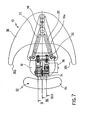
- arm 34 is suitable for rotating with respect to support 12 and is operatively associated with a rotating actuator 36.
- actuator 36 may be of the pneumatic, hydraulic or electrical type.
- one end of arm 34 is keyed onto a splined shaft 38 mounted on f rame 14.
- a gear 40 is suitable for being caused to rotate by rotating actuator 36 and transmit the motion to splined shaft 38 ( Figures 7 and 8 ).
- arm 34 is operatively associated with a cam 42 and a microswitch 44 preferably through splined shaft 38 ( Figures 7 and 8 ) with the function of checking that the opposing means has passed beyond a particular vertical position so as to ensure that the passenger is held.
- cam 42 has a first circular profile which extends over approximately three quarters of the total perimeter of the cam and a second circular profile of smaller radius than the first circular profile which extends over approximately one quarter of the total perimeter of the cam.
- the two profiles are suitably connected.
- microswitch 44 comprises a runner 46 which is hinged to a body of the microswitch and is provided at one end with a small wheel 48 which rotates with respect to the runner and can move over the profile of cam 42.
- arm 34 is operatively associated with means for immobilizing it in the raised position, for example comprising a rack 50 hinged on frame 14.
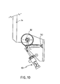
- the rack is associated with a toothed wheel 52 keyed onto splined shaft 38 to mechanically immobilize the opposing means in the raised position when it has reached the position in which it supports the passenger ( Figures 7 and 10 ).
- Rack 50 and toothed wheel 52 therefore comprise immobilizing means of the mechanical type to prevent movement of the opposing means either as a result of the movements of the amusement apparatus or the thrust of the passenger against the opposing means, preventing the passenger from being thrown out of the seat.
- rack 50 is kept in contact with and in mesh with toothed wheel 52, activated for example by a single-action pneumatic piston.
- rack 50 is held against toothed wheel 52 by resilient means which can be disabled, for example pneumatically, during the return movement of the opposing means.
- one end 54 of arm 34 can wrap partly round the user's back.
- cover or casing 26 is in the form of a motorcycle, as illustrated in Figures 13A-13D .
- Cover or casing 26 may be made, for example, from fiberglass.
- the seat 10 may include handlebars 200 and leg extensions 202, which may sit behind a user's knee to maintain the user's legs in a crouched motorcycle-like riding position.
- leg extensions 202 on either side of the seat 10 move between a retracted position, in which they lie against the cover or casing 26, and an extended position, in which they project out from each side of the cover or casing 26.
- a cushion 29 may be fixed to one end of arm 34, as shown in Figures 13 and 13A , or pivotally connected to arm 34, as shown in Figures 13E and 15 .
- the mechanism used to position arm 34, as shown in Figures 13E and 15 is the same as that used in the seat of Figure 1 except that it is adjusted to fit in the motorcycle shaped casing 26.
- a portion of arm 34 sits inside a recess 35 in a back wheel portion 37 of the casing when in the lowered position and sits in a recess 39 above the back wheel portion 37 when in the raised position.
- Figures 13E and 15 are side views of the seat of Figure 13A with the leg extensions 202 in the retracted and extended positions, respectively.
- Figures 14 and 16 are top views of Figure 13A , in which some components are in cross -section along the lines XIV and XVI, with the leg extension 202 in the retracted and extended positions, respectively.
- FIGs 13E and 14 to 16 For clarity, only a portion of the cover or casing 2 6 is shown in Figures 13E and 14 to 16 exposing the frame 14.
- An upward extending member 206 connects the handlebars 200 to the frame 14.
- a support plate 204 connected to the frame 14 is used to support the leg extensions 202, which are pivotally connect ed to the support plate 204 along axis A and axis B (behind axis A), as seen in Figures 13E and 15 , at points A and B, as seen in Figures 14 and 16 .
- Actuation means known in the art such as, for example, one or more motors, pumps, servos or hydraulic or g as pistons, may be used to move the leg extensions 202 between the retracted and extended positions.
- the actuation means may be, for example, of the pneumatic, hydraulic or electrical type.
- leg extensions 202 may be manually pivoted and locked in position using gears, cranks, cams, levers, etc.
- a piston 208 having a trigger head 210 is used to pivot the leg extensions 202 about points A and B between the retracted position ( Figures 13E and 14 ) and the extended position ( Figures 15 and 16 ).
- piston 208 may be flipped or reoriented such that it extends in the direction towards seat 10 and retracts away from seat 10.
- a biasing element such as a torsion spring 212, for example, may be used to bias the leg extensions 202 in the retracted position against the cover or casing 26.
- Trigger head 210 may have a recess 214 on each of opposing sides, which may pull a catch portion 216 on each of the leg extensions 202.
- the catch portion 216 of each leg extension 202 may be pulled towards the seat forcing one leg extension 202 to pivot about point A and the other leg extension 202 to simultaneously pivot about point B.
- each leg extension 202 may rotate in the recesses 214 on either side of the catch portion as the trigger head 210 moves in the direction of the arrow in Figure 14 .
- a portion 218 of each leg extension 202 may be drawn into the cover or casing 26 through a port or hole 220 ( Figures 13 and 13A ) on each side of the cover or casing 26.
- plate 204 may be connected to connected to other portions of frame 14, e.g., frontal supporting member 16 alone, frontal supporting member 16 and lateral supporting members 20, base plate 222 alone, etc.
- leg extensions 202 may be separately controlled by independent actuation means.
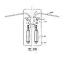
- Figures 17A and 17B show plate 204 including two separate pistons 224 for independent control of each of leg extensions 202. Pistons 224 may operate in a manner similar to that of piston 208.
- the leg extensions are shown in the retracted state in Figure 17A and in the extended state in Figure 17B .
- leg extensions 202 may each be independently controlled by a motor capable of forcing rotation of each leg extension about its respective pivot axis.
- the motors may be directly mounted on plate 204. Further, a single motor may be configured to control both leg extensions 202.
- the user whether a child or an adult, sits astride support 12 substantially as on a motor cycle and rests his chest or abdomen against support 30.
- cam 42 and microswitch 44 constitute a control for the position of arm 34.
- profile of cam 42 moves with respect to small wheel 48 causing runner 46 to rotate about the hinge point (the dashed and unbroken line in Figure 9 ).
- Rack 50 meshes with toothed wheel 52 and keeps the arm immobilized in the raised position thus opposing the movements of the amusement apparatus and the thrust from the passenger, thus preventing the passenger from leaving the seat.
- leg extensions 202 are triggered on the command of an operator, forcing leg extensions 202 to pivot about points A and B and move from the retracted position, as shown in Figures 13 , 13E and 14 , to the extended position, as shown in Figures 13A , 15 and 16 .
- the leg extensions 202 project to the side away from the cover or casing 26 directly behind a user's knees maintaining the user's legs in a crouched motorcycle -riding position.
- piston 53 compresses the spring which maintains contact between rack 50 and toothed wheel 52 while actuator 36 causes arm 34 to make its return travel. Further, piston 208 may be triggered again, this time forcing the trigger head 210 in an opposite direction, and thus, the leg extensions 202 to the retracted position.
- FIG. 11 and 12 An exemplary embodiment of apparatus provided with seats according to this invention is illustrated in Figures 11 and 12 .
- 100 indicates the apparatus as a whole comprising at least one track 102 on which a platform 104 can move.
- Platform 104 is mounted in such a way that it can rotate about an axis, for example an axis substantially perpendicular to the plane defined by the platform.
- At least one set of seats 10 is mounted on a substantially perimetral portion of the platform, preferably in such a way that the user faces outwards from the platform.
- the motion to which the user is subjected is the combination of the rotatory motion and the oscillatory motion of the platform. Provision may also be made for movement of the seats with respect to the platform.
- the seat according to this invention leaves the user's shoulders free and allows him to adopt a position similar to that adopted by motorcyclists.
- the motion of the opposing means, and in particular the arm can be brought about by means other than those described and illustrated.
- arm 34 may have a substantially circular shape with one toothed side suitable for meshing with a toothed wheel driven by the actuator.
- the frontal support may be movably mounted on the seat so that its position can be adjusted according to the user's dimensions.
- a continuous adjustment or a stepwise adjustment may be provided, or movement may be permitted to assist access from the side.
- the seat 10 may be substantially reversed with the provision of a movable frontal support and a fixed rear support. In each case the passenger sits astride the seat with his shoulders free.
- the frontal support may rotate or move linearly.
- FIG. 18A-18G An exemplary embodiment of an amusement apparatus provided with the seat of Figure 13A is illustrated in Figures 18A-18G .
- the amusement apparatus may also be provided with the seat 10 of Figure 1 .
- 300 indicates the apparatus as a whole comprising at least one track 302 on which one or more platforms 304 can move. Platforms 304 may be mounted in such a way that they can move along the track 302.
- Track 302 may include support rails 306 and cross beams 308.
- At least one seat 10 may be mounted on each of the platforms 304.
- the seat 10 may be situated on each platform 304 such that the length of the seat 10 runs along a longitudinal axis of the support rails 306 and such that a rider faces the direction of travel of the seat 10.
- two seats 10 are connected side -by-side on each platform 304.
- One or more foot guards 344 may be connected to each platform 304 to assure that a user's feet do not extend off the platform 304.
- the foot guard 344 may, for example, be constructed of tubing, as shown in Figure 18A , or a sheet of material, such as plexiglass, as shown in Figure 19 .
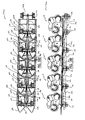
- the amusement apparatus 300 may include one or more platforms 304. As shown in Figures 18D -E , the amusement apparatus 300 may include five platforms including a leading platform 310 and a trailing platform 312. Only the leading two of the five platforms 304 are shown in Figures 18A -D . Each of the platforms 304 has a leading edge 318 and a trailing edge 320.
- the leading platform 310 may include a solid supporting surface having a contoured w -shaped leading edge 323.
- the trailing platform 312 may have a straight trailing edge 324 that extends transverse to the supporting rails 306.
- Each of the remainder of the platforms 304 may have a convex leading portion 318, for example, in the shape of a half circle, and a trailing portion 336 having a ma ting concave trailing edge 320, for example, in the shape of a half circle.
- the platforms 304 may be interconnected such that the convex leading edge 318 of each platform 304 fits in the concave trailing edge 320 of an adjacent platform 304.
- the leading portion 318 on a given platform 304 may be pivotally connected, for example, via hinges 338 ( Figure 18F ), to the trailing portion 336 so as to allow the platform 304 to enter horizontal and vertical curves with tighter radii.
- the leading platform 310 is shown as a solid planar support unit but may also include one or more hinged sections.
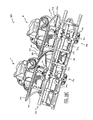
- Each platform 304 may be supported by a front axle 322 which may connected to and roll on each of the supporting rails 306 via a bogie 340, which may include, for example, two road wheels 324, one up-stop wheel 326 and two guide wheels 328.
- Pulley axles 332 may interconnect each of the front axles 322 and may be pivotably and rotatably connected on each end to the front axles 322.
- a trailing end of the pulley axle 332 of the trailing platform 312 may be connected to an independent axle 334, which is not used to support a platform 304.
- the platforms 304 may be interconnected such that the convex leading portion 318 of each platform 304 partially fits in the concave trailing portion 336 of an adjacent platform 304.
- rollers 342 may be connected to each of the pulley axles 332 such that the leading portion 318 may roll on rollers 342 and rotate within the adjacent trailing portion 336.
- the pulley axles 332 may interconnect the platforms 304 directly, i.e., they may be pivotally connected on both ends to the adjacent platforms, as opposed to being connected to the adjacent front axles 322.
- Each of the pulley axles 332 may include a fin 330 projecting downward away from the platform 304 towards the track cross members 308.
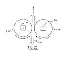
- one or more propulsion mechanisms including, for example, a pair of kicker motors 344, 346, may be connected to the track 302 and used to propel or brake the seats 10 via, for example, rolling contact of wheels 348 and 350 with the fins 330.
- Motors 344, 346 are shown freestanding and independent of the track 302 for clarity but may be mounted on the track, for example, to an upper surface of a support plate 341 ( Fig. 18C ).
- the track 302 may twist and turn and be supported via structures known in the art of roller coasters.
- the propulsion mechanisms may add potential energy to the train, i.e., the interconnected platforms 304, by driving the train to the top of a lift hill. Once the center of gravity of the train crests the apex of the lift hill gravity may be used to propel the train throughout the remainder of the track 302.
- a ride control system may be provided including, for example, a programmable logic controller (PLC), so as to monitor and actuate all necessary ride components such as the restraint releases, leg extensions 202, kicker motors 344, 346, etc.
- PLC programmable logic controller
- the ride control system may include proximity sensors and photo eyes.
Landscapes
- Seats For Vehicles (AREA)
- Chair Legs, Seat Parts, And Backrests (AREA)
- Toilet Supplies (AREA)
- Passenger Equipment (AREA)
- Chairs Characterized By Structure (AREA)
Abstract
Description
- This invention relates to an amusement apparatus and a seat for an amusement apparatus.
- In amusement apparatus, the user or passenger is generally seated on a suitable seat. For reasons of safety, the seat is often provided with means for immobilizing the user on the support of the seat in such a way that the user is firmly held in his seat despite the movements performed by the amusement apparatus Such an apparaturs is dsclosed in
WO 2004/073818 A1 . -
US 2004/0032157 A1 discloses a restraint bar for securing a person in vehicles for amusement rides, wherein the restraint bar is hinged at the top end of a seat and the end of the restraint bar opposite the hinge can he folded up to allow a person to board and get off. -
EP 1 215 091 A2 discloses device for locking the legs of a passenger in a seat on an installation for amusement parks comprising two flaps mounted for articulation at the end of the support of the base of the seat. -
US 5 979 333 discloses an amusement device includes a guide structure forming an endless track, along which a vehicle capable of accommodating at least one person can travel, and where a person present in the vehicle extends substantially parallel to the track during operation, wherein the person is secured via a support. - A seat for amusement apparatus including a fixed back and a fork hinged on the back above the user is for example known. The fork descends and immobilizes the user's shoulders and chest against the fixed back.
- A seat having this configuration immobilizes the user on the support of the seat, ensuring his safety, but doe s not allow the spectator to make movements of any kind, thus for example diminishing the ride sensation provided by the amusement apparatus, or one of the sensations which it is attempted to generate in order to render the amusement apparatus exciting.
- The need to construct amusement apparatus which can generate new sensations for users has always been felt within the sector. This requirement may for example be satisfied through the design of new seats which allow the user to adopt new positions and attitu des with respect to the apparatus.
- The problem underlying this invention is that of providing a seat for amusement apparatus which has structural and functional characteristics such as to distinguish it from the known art and to allow the user to adopt new positions on the apparatus.
- The present invention is directed to a seat for an amusement apparatus according to claim 1 and a method for maintaining the positioning of a rider on a seat for an amusement apparatus according to claim 74. In particular, a seat for amusement apparatus including a support and device for immobilizing the user on the support. The immobilizing device includes at least one support in front of the user and opposing arrangement suitable for acting on the user's back. The opposing arrangement includes an arm which may move between a lowered position in which the user can sit down on the support and a raised position in which one end of the arm abuts against the user's back. The seat comprises retractable extensions projecting from each side of the seat for maintaining a user's legs in a crouched motorcycle riding position. The seat may optionally have a motorcycle shape and may include handlebars.
- In an exemplary embodiment of the seat of the present invention, the support may include a seat portion and a front support member and may be configured to receive the rider astride the seat portion. The arrangement may be configured to secure the rider at least against the front support member at at least one of the abdominal portion of the rider and the thoracic portion of the rider.
- In an exemplary embodiment of the seat of the present invention, the support may include a seat portion and a front portion situated higher than the seat portion and angled such that a rider sitting astride on the seat portion must lean forward into a forward leaning posture for at least one of the passsenger's abdominal and thoracic regions to contact the front portion of the rider support. The arrangement may further include a restraint moveable between a first position not contacting the rider in the forward leaning posture and a second position in which at least a portion of the restraint contacts at least a back portion of the rider in the forward leaning posture and configured to maintain the rider in said forward leaning posture.
- In an exemplary embodiment of the seat of the present invention, the restraint may be pivotable between the first and second positions.
- In an exemplary embodiment of the seat of the present invention, at least one of the front portion and the restraint may include side portions arranged to at least partially wrap around a side of the rider.
- In an exemplary embodiment of the seat of the present invention, the restraint does not restrain shoulders of the rider.
- In an exemplary embodiment of the seat of the present invention, the support may be supported by a frame connected to a floor of the amusement apparatus.
- In an exemplary embodiment of the seat of the present invention, the restraint may be pivotally connected to the frame.
- In an exemplary embodiment of the seat of the present invention, the frame may include a frontal support member arranged at an angle to the floor and a support portion connected to one end of the frontal support member at an angle to the frontal support member.
- In an exemplary embodiment of the seat of the present invention, the front portion of the rider support may be connected to the support portion of the frame.
- In an exemplary embodiment of the seat of the present invention, the frame may include a frontal support member arranged at an angle to the floor, a support portion connected to the frontal support member and a pair of handlebars connected to one of the frontal support and the support portion.
- In an exemplary embodiment of the seat of the present invention, the frame may include at least one lateral support member connected to the floor on one end and the frontal support member at an opposite end.
- In an exemplary embodiment of the seat of the present invention, the seat may include a casing that at least partially covers the frame.
- In an exemplary embodiment of the seat of the present invention, the casing may be motorcycle shaped.
- In an exemplary embodiment of the seat of the present invention, the the restraint may include an arm and an opposing portion connected to the arm arranged to abut the riders back when the restraint is in the second position and the rider is in the forward leaning posture.
- In an exemplary embodiment of the seat of the present invention, the restraint may be operatively associated with one of a rotating actuator and a linear actuator.
- In an exemplary embodiment of the seat of the present invention, the arm may be operatively associated with a splined shaft and a gear rotatable by one of a rotating actuator and a linear actuator.
- In an exemplary embodiment of the seat of the present invention, the front portion of the rider support may be movably mounted on the seat such that a position of the front portion is adjustable according to a rider's dimensions.
- In an exemplary embodiment of the seat of the present invention, the arm may be operatively associated with a splined shaft having a cam connected thereto. Further, the cam may be configured to trigger a switch when the restraint is moved to a predetermined position.
- In an exemplary embodiment of the seat of the present invention, the switch may include a runner arm having a wheel rotatably connected to one end. Further, the profile of the cam may be configured to move with respect to the wheel to cause the runner arm to rotate about a switch hinge point.
- In an exemplary embodiment of the seat of the present invention, the cam may be circular and may include a first radius over a portion of the cam profile and a second smaller radius over another portion of the cam profile.
- In an exemplary embodiment of the seat of the present invention, the seat may include a lock configured to immobilize the arm when the restraint is in the second position and the rider is in the forward leaning posture.
- In an exemplary embodiment of the seat of the present invention, the lock may include a rack hinged on the frame and associated with a toothed wheel keyed on a splined shaft operatively associated with the arm.
- In an exemplary embodiment of the seat of the present invention, the seat may include resilient means for keeping the toothed wheel against the rack. The resilient means may be disabled during a return movement of the arm from the second position to the first position.
- In an exemplary embodiment of the seat of the present invention, the seat may include a pneumatic piston configured to keep the toothed wheel against the rack. The pneumatic piston may be configured to be pneumatically disabled during a return movement of the arm from the second position to the first position.
- In an exemplary embodiment of the seat of the present invention, the seat may be mounted on a platform of the amusement apparatus configured to move on at least one track.
- In an exemplary embodiment of the present invention, the the track may have a U-shape.
- In an exemplary embodiment of the seat of the present invention the platform may be circular.
- In an exemplary embodiment of the seat of the present invention, the seat may be arranged on at least one peripheral portion of the platform.
- In an exemplary embodiment of the seat of the present invention, the seat may be arranged such that the rider faces outwardly away from the platform.
- In an exemplary embodiment of the seat of the present invention, the seat may be arranged such that the rider faces in a traveling direction of the seat.
- In an exemplary embodiment of the seat of the present invention, a longitudinal axis of the seat portion of the seat may be arranged on the platform in a direction following the track.
- In an exemplary embodiment of the seat of the present invention, the platform may be configured to rotate relative to the track.
- In an exemplary embodiment of the seat of the present invention, the platform may include two or more hinged boards.
- In an exemplary embodiment of the seat of the present invention, the extensions in the extended position may be configured to extend behind knees of the rider and maintain legs of the rider bent at the knee in a motorcycle riding position.
- In an exemplary embodiment of the seat of the present invention, the extensions may include pivoting members which pivot between a retracted position, in which they lay substantially flat against respective sides of the seat allowing the rider to mount the seat unobstructed, and an extended position in which they project away from the respective sides of the seat.
- In an exemplary embodiment of the seat of the present invention, the seat may include an actuator for moving the members between the retracted and extended positions.
- In an exemplary embodiment of the seat of the present invention, the seat may include a support member and an actuator connected to the support member. The pivoting members may be pivotally connected towards one end to the support member and the actuator may be configured to move the pivoting members between the extended and retracted positions.
- In an exemplary embodiment of the seat of the present invention, the seat may include a frame and a casing that at least partially covers the frame. Each of the pivoting members may have a curved section at least a portion of which is outside the casing when in the retracted position and is inside the casing when in the extended position.
- In an exemplary embodiment of the seat of the present invention, the the casing may have a hole on either side through which the pivoting members extend.
- In an exemplary embodiment of the seat of the present invention, the actuator may include one or more pistons with a trigger head having at least one recess. The pivoting members may each have a catch portion spaced a predetermined distance away from a pivot point of the pivoting members on the support member. The trigger head may be configured to receive at least a portion of the catch portion in the at least one recess and to move away from and towards the piston. The pivoting members and the trigger head may be configured such that movement of the trigger head away from and towards the piston causes pivoting of the pivoting members about the pivot point between the extended and retracted positions.
- In an exemplary embodiment of the seat of the present invention, the support may include an elongated seat having a longitudinal axis. Further, the piston may be oriented in the same direction as the longitudinal axis.
- In an exemplary embodiment of the seat of the present invention, the actuator may include a pair of pistons, each piston controlling the movement of one of the pivoting members.
- In an exemplary embodiment of the present invention, the actuator may include a single piston. At least a portion of the catch portion of one pivoting member may be received in one recess on one side of the trigger head and at least a portion of the catch portion of the other pivoting member may be received in another recess on an opposite side of the trigger head.
- In an exemplary embodiment of the seat of the present invention, the seat may include at least one biasing element configured to force the extensions towards the retracted position.
- An exemplary amusement apparatus embodiment of the present invention may include at least one platform configured to move on at least one track and at least one seat connected to the platform. The seat may include: a support configured to receive a rider astride the support; an arrangement configured to immobilize the rider on the support, the arrangement configure to maintain shoulders of the rider free and to secure the rider on the support at at least one of an abdominal portion of the rider and a thoracic portion of the rider; and a pair of extensions configured to move between an extended position, in which a first one of the extensions projects outwardly from a first side of the seat and a second one of the extensions projects outwardly from a second side of the seat, and a retracted position, in which the extensions are retracted relative to the extended position.
- In an exemplary embodiment of the amusement apparatus of the present invention, the support may include a seat portion and a front support member and may be configured to receive the rider astride the seat portion. The arrangement may be configured to secure the rider at least against the front support member at at least one of the abdominal portion of the rider and the thoracic portion of the rider.
- In an exemplary embodiment of the amusement apparatus of the present invention, the support may include a seat portion and a front portion situated higher than the seat portion and angled such that the rider sitting astride on the seat portion must lean forward into a forward leaning posture for at.least one of the rider's abdominal and thoracic regions to contact the front portion of the rider support. The arrangement may include a restraint moveable between a first position not contacting the rider in the forward leaning posture and a second position in which at least a portion of the restraint contacts at least a back portion of the rider in the forward leaning posture and configured to maintain the rider in said forward leaning posture.
- In an exemplary embodiment of the amusement apparatus of the present invention, the at least one platform may be circular.
- In an exemplary embodiment of the amusement apparatus of the present invention, the at least one platform may be elongated and have a front edge and a trailing edge. The trailing edge may have a concave semi-circular contour.
- In an exemplary embodiment of the amusement apparatus of the present invention, the front edge may have a convex semi-circular contour.
- In an exemplary embodiment of the amusement apparatus of the present invention, the front edge may have a w shaped contour.
- An exemplary embodiment of the amusement apparatus of the present invention may further include at least two platforms, wherein a front portion of one platform has a convex semi-circular contour and fits in a rear portion of another platform having a concave semi-circular contour.
- In an exemplary embodiment of the amusement apparatus of the present invention, an axle may be connected to an underside of the platform and configured to support the platform on the at least one track. A pulley member may be pivotally connected on one end to the axle.
- In an exemplary embodiment of the amusement apparatus of the present invention, the other platform may include an axle connected to an underside. The pulley member may be pivotally connected to the axle of the other platform interconnecting the two platforms.
- In an exemplary embodiment of the amusement apparatus of the present invention, a front portion of the other platform may rest on rollers connected to the pulley member.
- In an exemplary embodiment of the amusement apparatus of the present invention, the platform may include at least two hinged portions.
- In an exemplary embodiment of the amusement apparatus of the present invention, the seat portion of the seat may be elongated and a longitudinal axis of the seat portion may be arranged to follow the track.
- In an exemplary embodiment of the amusement apparatus of the present invention, the seat may be arranged on at least one peripheral portion of the platform.
- In an exemplary embodiment of the amusement apparatus of the present invention, the seat may be arranged such that the rider faces outwardly away from the platform.
- In an exemplary embodiment of the amusement apparatus of the present invention, the platform may be configured to rotate relative to the track.
- In an exemplary embodiment of the amusement apparatus of the present invention, each platform may have connected to it two seats side-by-side.
- In an exemplary embodiment of the amusement apparatus of the present invention, the at least one platform may include a plurality of platforms inteconnected by pivotally connected pulley members.
- In an exemplary embodiment of the amusement apparatus of the present invention, the pulley member of one of the at least one platforms may be connected on one end to an independent axle not connected to a platform.
- An exemplary embodiment of the seat for an amusement apparatus of the present invention may include a support in the shape of a motorcycle configured to receive a rider astride the support and an arrangement configured to immobilize the rider on the support. The arrangement may be configured to maintain shoulders of the rider free and to secure the rider on the support at at least one of an abdominal portion of the rider and a thoracic portion of the rider.
- An exemplary embodiment of the amusement apparatus of the present invention may include at least one platform configured to move on at least one track and at least one motorcycle shaped seat connected to the platform. The at least one seat may include a support configured to receive a rider astride the support and an arrangement configured to immobilize the rider on the support. The arrangement may be configured to maintain shoulders of the rider free and to secure the rider on the support at at least one of an abdominal portion of the rider and a thoracic portion of the rider.
- An exemplary embodiment of the amusement apparatus of the present invention may include: a leading platform configured to move on at least one track; a trailing platform configured to move on the at least one track and including hinged leading and trailing portions; at least one seat configured to receive a rider connected to at least one of the leading and trailing platforms; at least one pulley member pivotally interconnecting the leading and trailing platforms; and at least one roller connected to the pulley member, the leading portion of the trailing platform supported on the at least one roller.
- In exemplary embodiment of the amusement apparatus of the present invention, each platform may be supported on the track by a supporting axle. Further, the pulley member may be pivotally connected on one end to the supporting axle supporting the leading platform and on the opposite end to the the supporting axle supporting the trailing platform.
- In exemplary embodiment of the amusement apparatus of the present invention, the leading portion of the trailing platform may have a convex contour which rotates at least partially within a concave contour of a trailing portion of the leading platform upon rotation of the platforms relative to each other.
- An exemplary embodiment of the seat of the present invention may include a support in the shape of a motorcycle configured to receive a rider astride the support and a pair of extensions configured to move between an extended position, in which a first one of the extensions projects outwardly from a first side of the seat and a second one of the extensions projects outwardly from a second side of the seat, and a retracted position, in which the extensions are retracted relative to the extended position.
- An exemplary embodiment of the amusement apparatus of the present invention may include a motor cycle shaped support configured to receive a rider astride the support and a pair of extensions configured to move between an extended position, in which a first one of the extensions projects outwardly from a first side of the seat and a second one of the extensions projects outwardly from a second side of the seat, and a retracted position, in which the extensions are retracted relative to the extended position.
- An exemplary embodiment of the seat of the present invention may include a rider support and opposing means. The rider support may include: a seat portion; a front portion situated higher than the seat portion and angled relative to a floor of the amusement apparatus such that a rider sitting astride on the seat portion must lean forward into a forward leaning posture for at least one of the rider's abdominal and thoracic regions to contact the front portion of the rider support; and extension means configured to exend from the seat behind the rider's knees and to maintain the rider's knees bent and in a crouched motorcycle riding position. The opposing means may be moveable between a first position not contacting the rider in the forward leaning posture and a second position wherein at least a portion of the restraint contacts at least a back portion of the rider in the forward leaning posture and configured to maintain the rider in said forward leaning posture.
- In exemplary embodiment of the seat of the present invention, the seat may include means for checking a position of the opposing means to assure that the rider is secured.
- In exemplary embodiment of the seat of the present invention, the seat may include means for immobilizing the opposing means in the second position.
- In exemplary embodiment of the amusement apparatus of the present invention, the seat may include means for moving the extension means between a high profile extended position and a lower profile retracted position, in which the extension means has a lower profile along each side of the seat.
- An exemplary embodiment of the present invention is a method for maintaining the positioning of a rider on a seat for an amusement apparatus. The seat may include a support configured to receive a rider astride the support and a pair of extensions configured to move between an extended position, in which a first one of the extensions projects outwardly from a first side of the seat and a second one of the extensions projects outwardly from a second side of the seat, and a retracted position, in which the extensions are retracted relative to the extended position. The method may include the step of extending the pair of extensions such that they extend behind the knees of the rider and maintain the rider in a crouched motor cycle riding position.
- An exemplary embodiment of a method of the present invention may include the step of securing the rider on the support at at least one of an abdominal portion of the rider and a thoracic portion of the rider while maintaining shoulders of the rider free.
- Other advantages and characteristics of the present invention will become clear from the following detailed description which is given with reference to the appended drawings which are provided purely by way of non -limiting example and in which:
-
Figure 1 illustrates a perspective view of the seat according to this invention, -
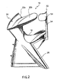
Figure 2 illustrates a side view of the seat inFigure 1 , -
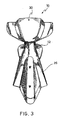
Figure 3 illustrates a frontal view of the seat inFigure 1 , -
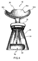
Figure 4 illustrates a rear view of the seat inFigure 1 , -
Figure 5 illustrates a side view of the seat inFigure 1 illustrating the position of the user, whe ther a child or an adult, -
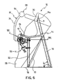
Figure 6 illustrates a side view of the seat inFigure 1 , -
Figure 7 illustrates a view of the seat inFigure 1 from above in which some components are in cross -section along the line VII-VII inFigure 6 , -
Figure 8 illustrates a view of a detail inFigure 7 in cross-section along the line VIII - VIII, -
Figure 9 illustrates a view of a detail inFigure 7 in cross-section along the line IX-IX, -
Figure 10 illustrates a view of a detail inFigure 7 in cross-section along the line X-X, -
Figure 11 illustrates a side view of an amusement apparatus including the seat ofFigure 1 , -
Figure 12 illustrates a view of the amusement apparatus inFigure 11 from above, -
Figure 13A illustrates a perspective view of the seat according to another exemplary embodiment of this invention; -
Figure 13B illustrates a top view of the seat ofFigure 13A , -
Figure 13C illustrates a front view of the seat ofFigure 13A , -
Figure 13D illustrates a back view of the seat ofFigure 13A , -
Figure 13E illustrates a side view of the seat ofFigure 13A with the frame exposed and the leg extension elements retracted, -
Figure 14 illustrates a view of the seat inFigure 13A from above in which some components are in cross -section along theline 14 inFigure 13E , -
Figure 15 illustrates a side view of the seat ofFigure 13A with the frame exposed and the leg extension elements extended, -
Figure 16 illustrates a view of the seat inFigure 13A from above in which some components are in cross -section along theline 16 inFigure 15 , -
Figure 17A illustrates a top view of a mechanism for extending and retracting the leg extension element with the leg extension element in a retracted position, -
Figure 17B illustrates the top view ofFigure 17A with the leg extension element in an extended pos ition, -
Figure 18A illustrates a front right perspective view of An amusement apparatus including the seat ofFigure 13A , -
Figure 18B illustrates a front left perspective view of the amusement apparatus ofFigure 18A , -
Figure 18C illustrates a bottom perspective view of the amusement apparatus ofFigure 18A , -
Figure 18D illustrates a bottom view of the amusement apparatus ofFigure 18A including three additional sections, -
Figure 18E illustrates a side view of the amusement apparatus ofFigure 18A including three additional sections, -
Figure 18F illustrates a top view of a single seat platform with the seats removed, -
Figure 18G illustrates a back view of the single platform ofFigure 18F mounted on a amusement apparatus rail, -
Figure 19 illustrates a perspective view of an exemplary embodiment of the amusement apparatus including the seat ofFigure 13A , and -
Figure 20 is a schematic view of an exemplary embodiment of a pair of kicker motors used to propel the platforms. - With reference to the abovementioned figures, a seat for amusement apparatus is indicated as a whole by 10.
- As the appended figures illustrate,
seat 10 is advantageously constructed in such a way that the passenger or user sits astride the same, adopting a posture similar to that adopted by motorcyclists. - In addition to this the structure of the seat is such as to leave the passenger's shoulders free, securing him in the vicinity of the chest or abdomen.
- According to an
exemplary embodiment seat 10 compris es asupport 12 supported by aframe 14. Forexample support 12 is in the shape of a saddle or motor vehicle seat so as to receive the passenger sitting astride the same. - According to an
exemplary embodiment frame 14 is for example constructed of a set of tubular members, although other embodiments such as compact and boxed structures are possible. -
Figure 6 illustrates an exemplary embodiment offrame 14 in which frontal supportingmember 16 is fixed to afloor 18. Frontal supportingmember 16 extends fromfloor 18 preferably in a direction which is inclined at an angle of a with respect to the floor. - The extremity of the frontal supporting member opposite
floor 18 ends in aportion 16a which is preferably inclined at an angle β with respect to the frontal supporting member.Portion 16a is suitable for supporting a cushion to support the passenger, which is for example manufactured from polyurethane. - Two
lateral supporting members 20 extend from frontal supportingmember 16 andfloor 18. Further supportingmembers 22 extend in a direction substantially perpendicular tofloor 18 and constitute a support for supportingmembers 24 forsupport 12. - A cover or
casing 26 completely enclosesframe 14 ofseat 10. - 28 indicates means for immobilizing the user on
support 12 of the seat. These immobilizing means advantageously comprise at least onesupport 30 mounted at the end of frontal supportingmember 16 in the vicinity ofportion 16a.Support 30 is located frontally with respect to the user and according to an exemplary embodiment has a shape such as to wrap round the passenger both at the front and at the side. Forexample support 30 comprises acentral portion 30a which may comprise a supporting member for a frontal port ion of the user, for example the chest in the case of children or the abdomen in the case of adults. Advantageously twoside portions 30b, which are preferably arched, are also provided and extend fromcentral portion 30a and have a configuration such as to surround the passenger laterally. - Immobilizing means 28 advantageously also comprise opposing means 32 suitable for acting against the user's back. According to an exemplary embodiment the opposing means can move between an open position and a closed pos ition in which it abuts against the user's back.
Figure 5 illustrates three positions of the opposing means corresponding to the open position (lowered position illustrated by a dashed line), the closed position (raised position illustrated by the unbroken line) and a position intermediate between the open position and the closed position (illustrated by a dashed line). - According to an exemplary embodiment, which is for example illustrated in the figures, opposing means 32 comprises an
arm 34 which can move between a lowered position in which the user can sit down on the support of the seat and a raised position in which one end of the arm abuts against the user's back (Figure 5 ). Preferablyarm 34 is suitable for rotating with respect to support 12 and is operatively associated with a rotatingactuator 36. According to an exemplary embodiments actuator 36 may be of the pneumatic, hydraulic or electrical type. - According to an exemplary embodiment one end of
arm 34 is keyed onto asplined shaft 38 mounted onf rame 14. - A
gear 40 is suitable for being caused to rotate by rotatingactuator 36 and transmit the motion to splined shaft 38 (Figures 7 and8 ). - According to an
exemplary embodiment arm 34 is operatively associated with acam 42 and amicroswitch 44 preferably through splined shaft 38 (Figures 7 and8 ) with the function of checking that the opposing means has passed beyond a particular vertical position so as to ensure that the passenger is held. - According to an
exemplary embodiment cam 42 has a first circular profile which extends over approximately three quarters of the total perimeter of the cam and a second circular profile of smaller radius than the first circular profile which extends over approximately one quarter of the total perimeter of the cam. The two profiles are suitably connected. - According to an
exemplary embodiment microswitch 44 comprises arunner 46 which is hinged to a body of the microswitch and is provided at one end with asmall wheel 48 which rotates with respect to the runner and can move over the profile ofcam 42. - According to an
exemplary embodiment arm 34 is operatively associated with means for immobilizing it in the raised position, for example comprising arack 50 hinged onframe 14. in particular the rack is associated with atoothed wheel 52 keyed ontosplined shaft 38 to mechanically immobilize the opposing means in the raised position when it has reached the position in which it supports the passenger (Figures 7 and10 ).Rack 50 andtoothed wheel 52 therefore comprise immobilizing means of the mechanical type to prevent movement of the opposing means either as a result of the movements of the amusement apparatus or the thrust of the passenger against the opposing means, preventing the passenger from being thrown out of the seat. - According to an
exemplary embodiment rack 50 is kept in contact with and in mesh withtoothed wheel 52, activated for example by a single-action pneumatic piston. Inparticular rack 50 is held againsttoothed wheel 52 by resilient means which can be disabled, for example pneumatically, during the return movement of the opposing means. - According to an exemplary embodiment, one
end 54 ofarm 34 can wrap partly round the user's back. - According to an exemplary embodiment, cover or
casing 26 is in the form of a motorcycle, as illustrated inFigures 13A-13D . Cover orcasing 26 may be made, for example, from fiberglass. In this exemplary embodiment, theseat 10 may includehandlebars 200 andleg extensions 202, which may sit behind a user's knee to maintain the user's legs in a crouched motorcycle-like riding position. As can be seen, for example, inFigures 13E to 16 ,leg extensions 202 on either side of theseat 10 move between a retracted position, in which they lie against the cover orcasing 26, and an extended position, in which they project out from each side of the cover orcasing 26. Acushion 29 may be fixed to one end ofarm 34, as shown inFigures 13 and13A , or pivotally connected toarm 34, as shown inFigures 13E and15 . The mechanism used to positionarm 34, as shown inFigures 13E and15 , is the same as that used in the seat ofFigure 1 except that it is adjusted to fit in the motorcycle shapedcasing 26. A portion ofarm 34 sits inside arecess 35 in aback wheel portion 37 of the casing when in the lowered position and sits in arecess 39 above theback wheel portion 37 when in the raised position. -
Figures 13E and15 are side views of the seat ofFigure 13A with theleg extensions 202 in the retracted and extended positions, respectively.Figures 14 and16 are top views ofFigure 13A , in which some components are in cross -section along the lines XIV and XVI, with theleg extension 202 in the retracted and extended positions, respectively. For clarity, only a portion of the cover or casing 2 6 is shown inFigures 13E and14 to 16 exposing theframe 14. An upward extendingmember 206 connects thehandlebars 200 to theframe 14. Asupport plate 204 connected to theframe 14 is used to support theleg extensions 202, which are pivotally connect ed to thesupport plate 204 along axis A and axis B (behind axis A), as seen inFigures 13E and15 , at points A and B, as seen inFigures 14 and16 . - Actuation means known in the art, such as, for example, one or more motors, pumps, servos or hydraulic or g as pistons, may be used to move the
leg extensions 202 between the retracted and extended positions. The actuation means may be, for example, of the pneumatic, hydraulic or electrical type. Further,leg extensions 202 may be manually pivoted and locked in position using gears, cranks, cams, levers, etc. According to an exemplary embodiment, as best seen in the top views ofFigures 14 and16 , apiston 208 having atrigger head 210 is used to pivot theleg extensions 202 about points A and B between the retracted position (Figures 13E and 14 ) and the extended position (Figures 15 and 16 ). According to an exemplary embodiment,piston 208 may be flipped or reoriented such that it extends in the direction towardsseat 10 and retracts away fromseat 10. - As seen in side views
Figures 13E and15 , a biasing element, such as atorsion spring 212, for example, may be used to bias theleg extensions 202 in the retracted position against the cover orcasing 26.Trigger head 210 may have arecess 214 on each of opposing sides, which may pull acatch portion 216 on each of theleg extensions 202. As thetrigger head 210 is pulled by thepiston 208 towards theseat 10, i.e., from the position shown inFigure 14 towards the position shown inFigures 15 and 16 , thecatch portion 216 of eachleg extension 202 may be pulled towards the seat forcing oneleg extension 202 to pivot about point A and theother leg extension 202 to simultaneously pivot about point B. Thecatch portions 216 of eachleg extension 202 may rotate in therecesses 214 on either side of the catch portion as thetrigger head 210 moves in the direction of the arrow inFigure 14 . As theleg extensions 202 are extended, aportion 218 of eachleg extension 202, previously outside the cover orcasing 26, may be drawn into the cover orcasing 26 through a port or hole 220 (Figures 13 and13A ) on each side of the cover orcasing 26. - According to an
exemplary embodiment plate 204 may be connected to connected to other portions offrame 14, e.g., frontal supportingmember 16 alone, frontal supportingmember 16 andlateral supporting members 20,base plate 222 alone, etc. - According to an exemplary embodiment, the
leg extensions 202 may be separately controlled by independent actuation means.Figures 17A and17B show plate 204 including twoseparate pistons 224 for independent control of each ofleg extensions 202.Pistons 224 may operate in a manner similar to that ofpiston 208. The leg extensions are shown in the retracted state inFigure 17A and in the extended state inFigure 17B . - According to an exemplary embodiment the
leg extensions 202 may each be independently controlled by a motor capable of forcing rotation of each leg extension about its respective pivot axis. The motors may be directly mounted onplate 204. Further, a single motor may be configured to control bothleg extensions 202. - The manner in which the seat for amusement apparatus as described above is used is described below.
- The user, whether a child or an adult, sits astride
support 12 substantially as on a motor cycle and rests his chest or abdomen againstsupport 30. - On the command of an
operator actuator 36 causes splinedshaft 38 and thereforearm 34 to rotate until the latter abuts against the user's back.Cam 42 andmicroswitch 44 constitute a control for the position ofarm 34. In particular the profile ofcam 42 moves with respect tosmall wheel 48 causingrunner 46 to rotate about the hinge point (the dashed and unbroken line inFigure 9 ). -
Rack 50 meshes withtoothed wheel 52 and keeps the arm immobilized in the raised position thus opposing the movements of the amusement apparatus and the thrust from the passenger, thus preventing the passenger from leaving the seat. - For the exemplary embodiment of
Figure 13A , on the command of an operator,piston 208 is triggered forcingleg extensions 202 to pivot about points A and B and move from the retracted position, as shown inFigures 13 ,13E and 14 , to the extended position, as shown inFigures 13A ,15 and 16 . Theleg extensions 202 project to the side away from the cover orcasing 26 directly behind a user's knees maintaining the user's legs in a crouched motorcycle -riding position. - To release the passenger single -acting
piston 53 compresses the spring which maintains contact betweenrack 50 andtoothed wheel 52 whileactuator 36 causesarm 34 to make its return travel. Further,piston 208 may be triggered again, this time forcing thetrigger head 210 in an opposite direction, and thus, theleg extensions 202 to the retracted position. - An exemplary embodiment of apparatus provided with seats according to this invention is illustrated in
Figures 11 and 12 . 100 indicates the apparatus as a whole comprising at least onetrack 102 on which aplatform 104 can move.Platform 104 is mounted in such a way that it can rotate about an axis, for example an axis substantially perpendicular to the plane defined by the platform. - At least one set of
seats 10 is mounted on a substantially perimetral portion of the platform, preferably in such a way that the user faces outwards from the platform. - The motion to which the user is subjected is the combination of the rotatory motion and the oscillatory motion of the platform. Provision may also be made for movement of the seats with respect to the platform.
- From what has been stated above it will be appreciated that the provision of a seat for amusement apparatus according to this invention makes it possible to satisfy the requirement for obtaining a different position of the user on the apparatus, changing the sensations provoked in the user without the need for any drastic modification in the structure of the apparatus.
- In particular the seat according to this invention leaves the user's shoulders free and allows him to adopt a position similar to that adopted by motorcyclists.
- It is clear that variants and/or additions may be provided to what has been described and illustrated above.
- Regardless of the embodiment, provision is advantageously made for the opposing means to rotate or move laterally with respect to the support.
- According to an exemplary embodiment, the motion of the opposing means, and in particular the arm, can be brought about by means other than those described and illustrated. For
example arm 34 may have a substantially circular shape with one toothed side suitable for meshing with a toothed wheel driven by the actuator. - As an alternative to what is illustrated in the appended figures, the frontal support may be movably mounted on the seat so that its position can be adjusted according to the user's dimensions. In this case a continuous adjustment or a stepwise adjustment may be provided, or movement may be permitted to assist access from the side.
- According to an exemplary embodiment, the
seat 10 may be substantially reversed with the provision of a movable frontal support and a fixed rear support. In each case the passenger sits astride the seat with his shoulders free. The frontal support may rotate or move linearly. - An exemplary embodiment of an amusement apparatus provided with the seat of
Figure 13A is illustrated inFigures 18A-18G . The amusement apparatus may also be provided with theseat 10 ofFigure 1 . 300 indicates the apparatus as a whole comprising at least onetrack 302 on which one ormore platforms 304 can move.Platforms 304 may be mounted in such a way that they can move along thetrack 302.Track 302 may include support rails 306 and cross beams 308. - At least one
seat 10 may be mounted on each of theplatforms 304. Theseat 10 may be situated on eachplatform 304 such that the length of theseat 10 runs along a longitudinal axis of the support rails 306 and such that a rider faces the direction of travel of theseat 10. As shown inFigures 18A-18C twoseats 10 are connected side -by-side on eachplatform 304. One ormore foot guards 344 may be connected to eachplatform 304 to assure that a user's feet do not extend off theplatform 304. Thefoot guard 344 may, for example, be constructed of tubing, as shown inFigure 18A , or a sheet of material, such as plexiglass, as shown inFigure 19 . - The
amusement apparatus 300 may include one ormore platforms 304. As shown inFigures 18D -E , theamusement apparatus 300 may include five platforms including a leadingplatform 310 and a trailingplatform 312. Only the leading two of the fiveplatforms 304 are shown inFigures 18A -D . Each of theplatforms 304 has aleading edge 318 and a trailingedge 320. The leadingplatform 310 may include a solid supporting surface having a contoured w -shapedleading edge 323. The trailingplatform 312 may have astraight trailing edge 324 that extends transverse to the supporting rails 306. Each of the remainder of theplatforms 304 may have a convex leadingportion 318, for example, in the shape of a half circle, and a trailingportion 336 having a ma ting concave trailingedge 320, for example, in the shape of a half circle. Theplatforms 304 may be interconnected such that the convexleading edge 318 of eachplatform 304 fits in theconcave trailing edge 320 of anadjacent platform 304. - The leading
portion 318 on a givenplatform 304 may be pivotally connected, for example, via hinges 338 (Figure 18F ), to the trailingportion 336 so as to allow theplatform 304 to enter horizontal and vertical curves with tighter radii. The leadingplatform 310 is shown as a solid planar support unit but may also include one or more hinged sections. - Each
platform 304 may be supported by afront axle 322 which may connected to and roll on each of the supportingrails 306 via abogie 340, which may include, for example, tworoad wheels 324, one up-stop wheel 326 and twoguide wheels 328. Pulley axles 332 may interconnect each of thefront axles 322 and may be pivotably and rotatably connected on each end to thefront axles 322. A trailing end of thepulley axle 332 of the trailingplatform 312 may be connected to anindependent axle 334, which is not used to support aplatform 304. - As indicated above, the
platforms 304 may be interconnected such that the convex leadingportion 318 of eachplatform 304 partially fits in the concave trailingportion 336 of anadjacent platform 304. As can be seen inFigure 18D ,rollers 342 may be connected to each of thepulley axles 332 such that the leadingportion 318 may roll onrollers 342 and rotate within the adjacent trailingportion 336. - In an exemplary embodiment of the invention, the
pulley axles 332 may interconnect theplatforms 304 directly, i.e., they may be pivotally connected on both ends to the adjacent platforms, as opposed to being connected to the adjacentfront axles 322. - Each of the
pulley axles 332 may include afin 330 projecting downward away from theplatform 304 towards thetrack cross members 308. As shown inFigure 20 , one or more propulsion mechanisms, including, for example, a pair ofkicker motors track 302 and used to propel or brake theseats 10 via, for example, rolling contact ofwheels fins 330.Motors track 302 for clarity but may be mounted on the track, for example, to an upper surface of a support plate 341 (Fig. 18C ). - The
track 302 may twist and turn and be supported via structures known in the art of roller coasters. The propulsion mechanisms may add potential energy to the train, i.e., theinterconnected platforms 304, by driving the train to the top of a lift hill. Once the center of gravity of the train crests the apex of the lift hill gravity may be used to propel the train throughout the remainder of thetrack 302. - A ride control system may be provided including, for example, a programmable logic controller (PLC), so as to monitor and actuate all necessary ride components such as the restraint releases,
leg extensions 202,kicker motors
Claims (75)
- A seat (10) for an amusement apparatus, comprising:a support configured to receive a rider astride the support;an arrangement (34, 29) configured to immobilize the rider on the support, the arrangement (34, 29) configured to maintain shoulders of the rider free and to secure the rider on the support at at least one of an abdominal portion of the rider and a thoracic portion of the rider; anda pair of extensions (202),characterized in that the pair of extensions (202) being configured to move between an extended position, in which a first one of the extensions (202) projects outwardly from a first side of the seat (10) and a second one of the extensions (202) projects outwardly from a second side of the seat (10), and a retracted position, in which the extensions (202) are retracted relative to the extended position the extensions (202) in the extended position are configured to extend behind the knees of the rider maintaining the rider's knees bent in a crouched motorcycle riding position.
- The seat (10) of claim 1, characterized in that the
support includes a seat (10) portion and a front support member and is configured to receive the rider astride the seat portion, the arrangement (34, 29) configured to secure the rider at least against the front support member at at least one of the abdominal portion of the rider and the thoracic portion of the rider. - The seat (10) of claim 1 or 2, characterized in that the support includes a seat portion and a front portion situated higher than the seat portion and angled such that a rider sitting astride on the seat portion must lean forward into a forward leaning posture for at least one of the passsenger's abdominal and thoracic regions to contact the front portion of the rider support,
the arrangement (34, 29) including a restraint moveable between a first position not contacting the rider in the forward leaning posture and a second position in which at least a portion of the restraint contacts at least a back portion of the rider in the forward leaning posture and configured to maintain the rider in said forward leaning posture. - The seat (10) of claim 3, characterized in that the restraint is pivotable between the first and second positions.
- The seat (10) of claim 3 or 4, characterized in that at least one of the front portion and the restraint include side portions arranged to at least partially wrap around a side of the rider.
- The scat (10) of claim 3, 4 or 5, characterized in that the restraint does not restrain shoulders of the rider.
- The seat (10) of one of the claims 3 through 6, characterized in that the support is supported by a frame connected to a floor of the amusement apparatus.
- The seat (10) of one of the claims 3 through 7, characterized in that the restraint is pivotally connected to the frame.
- The seat (10) of claim 7 or 8, characterized in that Lhe frame includes a frontal support member arranged at an angle to the floor and a support portion connected to one end of the frontal support member at an angle to the frontal support member.
- The seat (10) of claim 9, characterized in that The front portion of the rider support is connected to the support portion of the frame.
- The seat (10) of one of the claims 7 through 10, characterized in that the frame includes a frontal support member arranged at an angle to the floor, a support portion connected to the frontal support member and a pair of handlebars connected to one of the frontal support and the support portion.
- The seat (10) of claim 9, 10 or 11, characterized in that the frame includes at least one lateral support member connected to the floor on one end and the frontal support member at an opposite end.
- The seat (10) of one of the claims 7 through 12, characterized in that the seat (10) further comprising a casing that at least partially covers the frame.
- The seat (10) of claim 13, characterized in that the casing is in the shape of a motorcycle.
- The seat (10) of one of Lhe claims 3 through 14, characterized in that the restraint includes an arm and an opposing portion connected to the arm arranged to abut the riders back when the restraint is in the second position and the rider is in the forward leaning posture.
- The seat (10) of one of the claims 3 through 15, characterized in that the restraint is operatively associated with one of a rotating actuator and a linear actuator.
- The seat (10) of claim 15 or 16, characterized in that the arm is operatively associated with a splined shaft and a gear rotatable by one of a rotating actuator and a linear actuator.
- The seat (10) of one of the claims 3 through 17, characterized in that the front portion of the rider support is movably mounted on the seat (10) such that a position of the front portion is adjustable according to a rider's dimensions.
- The seat (10) of claim 15, 16, 17 or 18, characterized in that the arm is operatively associated with a splined shaft having a cam connected thereto, the cam configured to trigger a switch when the restraint is moved to a predetermined position.
- The seat (10) of claim 19, characterized in that the switch includes a runner arm having a wheel rotatably connected to one end, and wherein a profile of the cam is configured to move with respect to the wheel to cause the runner arm to rotate about a switch hinge point.
- The seat (10) of claim 19 or 20, characterized in that the cam is circular and includes a first radius over a portion of the cam profile and a second smaller radius over another portion of the cam profile.
- The seat (10) of one of the claims 15 through 21, characterized in that the seat (10) further comprising a lock configured to immobilize the arm when Lhe restraint is in the second position and the rider is in the forward leaning posture.
- The seat (10) of claim 22, characterized in that the lock includes a rack hinged on the frame and associated with a toothed wheel keyed on a splined shaft operatively associated with the arm.
- The seat (10) of claim 23, characterized in that the seat (10) further including resilient means for keeping the toothed wheel against the rack, said resilient means disabled during a return movement of the arm from the second position to the first position.
- The seat (10) of claim 23 or 24, characterized in that the seat (10) further comprising a pneumatic piston configured to keep the toothed wheel against the rack, said pneumatic piston configured to be pneumatically disabled during a return movement of the arm from the second position to the first position.
- The seat (10) of one of the claims 1 through 25, characterized in that the seat (10) is mounted on a platform of the amusement apparatus configured to move on at least one track.
- The seat (10) of claim 26, characterized in that the track has a U-shape.
- The seat (10) of claim 26 or 27, characterized in that the platform is circular.
- The seat (10) of claim 28, characterized in that the seat (10) is arranged on at least one peripheral portion of the platform.
- The seat (10) of claim 28 or 29, characterized in that the seat (10) is arranged such that the rider faces in a traveling direction of the seat (10).
- The seat (10) of one of the claims 26 through 30, characterized in that a longitudinal axis of the seat portion of the seat (10) is arranged on the platform in a direction following the track.
- The seat (10) of one of the claims 26 through 31, characterized in that Lhe platform is configured Lo rotate relative to the track.
- The seat (10) of one of the claims 26 through 32, characterized in that the platform comprises two or more hinged boards.
- The seat (10) of one of the claims 1 through 33, characterized in that the extensions (202) comprise pivoting members which pivot between a retracted position, in which they lay substantially flat against respective sides of the seat (10) allowing the ri.der to mount the seat (10) unobstructed, and an extended position in which they project away from the respective sides of the seat (10).
- The seat (10) of claim 36, characterized in that the scat (10) further comprising an actuator for moving the members between the retracted and extended positions.
- The seat (10) of claim 34 or 35, characterized in that the seat (10) further comprising a support member and an actuator connected to the support member, said pivoting members pivotally connected towards one end to the support member, Lhe actuator configured to move the pivoting members between Lhe extended and retracted positions.
- The seat (10) of claim 35 or 36, characterized in that the seat (10) further comprising a frame and a casing that at least partially covers the frame, each of the pivoting members having a curved section at least a portion of which is outside the casing when in the retracted position and is inside the casing when in the extended position.
- The seat (10) of claim 37, characterized in that the casing has a hole on either side through which the pivoting members extend.
- The seat (10) of claim 36, 37 or 38, characterized in that the actuator comprises one or more pistons with a trigger head having at least one recess, the pivoting members each having a catch portion spaced a predetermined distance away from a pivot point of the pivoting members on the support member, said trigger head configured to receive at least a portion of the catch portion in the at least one recess and to move away from and towards the piston, the pivoting members and the trigger head configured such that movement of the trigger head away from and towards the piston causes pivoting of the pivoting members about the pivot point between the extended and retraced positions.
- The seat (10) of claim 39, characterized in that the support includes an elongated seat (10) having a longitudinal axis and wherein the piston is oriented in Lhe same direction as the longitudinal axis.
- The seat (10) of claim 39 or 40, characterized in that the actuator includes a pair of pistons, each piston controlling the movement of one of the pivoting members.
- The seat (10) of claim 39, 40 or 41 , characterized in that the actuator comprises a single piston, at least a portion of the catch portion of one pivoting member is received in one recess on one side of the trigger head and at least a portion of the catch portion of the other pivoting member is received in another recess on an opposite side of the trigger head.
- The seat (10) of one of the claims 1 through 42, characterized in that the seat (10) further includes at least one biasing element configured to force the extensions (202) towards the retracted position.
- An amusement apparatus, comprising:a) at least one platform configured to move on at least one track; andb) at least one seat (10), according to one of the preceeding claims, connected to the platform,
- The amusement apparatus of claim 44, characterized in that the support includes a seat portion and a front support member and is configured to receive the rider astride the scat portion, the arrangement (34, 29) is configured to secure the rider at least against the front support member at at least one of the abdominal portion of the rider and the thoracic portion of the rider.
- The amusement apparatus of claim 44 or 45, characterized in that the support includes a seaL portion and a front portion situated higher than the seat portion and angled such that the rider sitting astride on the seat portion must lean forward into a forward leaning posture for at least one of the rider's abdominal and thoracic regions to contact the front portion of the rider support, the arrangement (34, 29) including a restraint moveable between a first position not contacting the rider in the forward leaning posture and a second position in which at least a portion of the restraint contacts at least a back portion of the rider in the forward leaning posture and configured to maintain the rider in said forward leaning posture.
- The amusement apparatus of claim 44, 45 or 46, characterized in that the at least one platform is circular.
- The amusement apparatus of claim 44, 45, 46 or 47, characterized in that the at least one platform is elongated and has a front edge and a trailing edge, the trailing edge having a concave semi-circular contour.
- The amusement apparatus of claim 48, characterized in that the front edge has convex semi-circular contour.
- The amusement apparatus of claim 48 or 49, characterized in that the front edge has a w shaped contour.
- The amusement apparatus of one of the claims 44 through 50, characterized in that the amusement apparatus further comprising at least two platforms wherein a front portion of one platform has a convex semi-circular contour and fits in a rear portion of another platform having a concave semi-circular contour.
- The amusement apparatus of one of the claims 44 through 51, characterized in that the amusement apparatus further comprising an axle, connected to an underside of the platform and configured to support the platform on the at least one track, and a pulley member pivotally connected on one end to the axle.
- The amusement apparatus of claim 52, characterized in that the amusement apparatus further comprising another platform including an axle connected to an underside of said other platform, wherein the pulley member is pivotally connected to the axle of the other platform interconnecting the two platforms.
- The amusement apparatus of claim 53 characterized in that a front portion of the other platform rests on rollers connected to the pulley member.
- The amusement apparatus of one of the claims 44 through 54, characterized in that the platform comprises at least two hinged portions.
- The amusement apparatus of one of the claims 44 through 55, characterized in that the scat portion of the seat (10) is elongated and a longitudinal axis of the seat portion is arranged to follow the track.
- The amusement apparatus of one of the claims 44 through 56, characterized in that the amusement apparatus is arranged on at least one peripheral portion of the platform.
- The amusement apparatus of one of the claims 44 through 57, characterized in that the amusement apparatus is arranged such that the rider faces outwardly away from the platform.
- The amusement apparatus of one of the claims 44 through 58, characterized in that the platform is configured to rotate relative to the track.
- The amusement apparatus of one of the claims 44 through 59, characterized in that each platform has connected to it two seats (10) side-by-side.
- The amusement apparatus of one of the claims 44 through 60, characterized in that the at least, one platform includes a plurality of platforms inteconnected by pivotally connected pulley members.
- The amusement apparatus of one of the claims 53 through 61, characterized in that the pulley member of one of the at least one platforms is connected on one end to an independent axle not connected to a platform.
- A scat (10) for an amusement, apparatus, in particular a scat (10) according to one of the claims 1 through 43, characterized in that the seat (10) comprising:a support in the shape of a motorcycle configured to receive a rider astride the support; andan arrangement (34, 29) configured to immobilize the rider on the support, the arrangement (34, 29) configured to maintain shoulders of the rider free and to secure the rider on the support at at least one of an abdominal portion of the rider and a thoracic portion of the rider.
- An amusement apparatus, in particular according to one of the claims 44 through 63, characterized in that Lhc amusement apparatus comprising:a) at least one platform configured to move on at least one track; andb) at least one motorcycle shaped seat (10) connected to the platform, the at least one seat (10) including:(i) a support configured to receive a rider astride the support; and(ii) an arrangement (34, 29) configured to immobilize the rider on the support, the arrangement (34, 29) configured to maintain shoulders of the rider free and to secure the rider on the support at at least one of an abdominal portion of the ride and a thoracic portion of the rider.
- An amusement apparatus, in particular according to one of the claims 44 through 63, characterized in that the amusement apparatus comprising:a) a leading platform configured to move on at least one track;b) a trailing platform configured to move on the at least one track and including hinged leading and trailing portions;c) at least one seat (10) configured to receive a rider connected to at least one of the leading and trailing platforms;d) at least one pulley member pivotally interconnecting the leading and trailing platforms; ande) at least one roller connected to the pulley member, the leading portion of the trailing platform supported on the at least one roller.
- The amusmenL apparatus of claim 65, characterized in that each platform is supported on the track by a supporting axle, the pulley member being pivotally connected on one end to the supporting axle supporting the leading platform and on the opposite end to the the supporting axle supporting the trailing platform.
- The amusement apparatus of claim 65 or 66, characterized in that the leading portion of the trailing platform has a convex contour which rotates at least partially within a concave contour of a trailing portion of the leading platform upon rotation of the platforms relative to each other.
- A seat (10) for an amusement apparatus, in particular a seat (10) according to one of the claims 1 through 43, characterized in that the scat (10) comprising:a support, in the shape of a motorcycle configured to receive a rider astride the support; anda pair of extensions (202) configured to move between an extended position, in which a first one of the extensions (202) project outwardly from a first side oF the seat (10) and a second one of the extensions (202) projects outwardly from a second side of the seat (10), and a retracted position, in which the extensions (202) are retracted relative to the extended position.
- A seat (10) for an amusement apparatus, in particular a seat (10) according to one of the claims 1 through 43, characterized in that the seat (10)comprising:a motor cycle shaped support configured to receive a rider astride the support; anda pair of extensions (202) configured to move between an extended position, in which a first one of the extensions (202) projects outwardly from a first side of the seat (10) and a second one of the extensions (202) projects outwardly from a second side of the seat (10), and a retracted position, in which the extensions (202) are retracted relative to the extended position.
- A seat (10) for an amusement apparatus, in particular a seat (10) according to one of the claims 1 through 43, characterized in that the scat (10)comprising:(a) a rider support including:(i) a seat portion;(ii) a front portion situated higher than the seat portion and angled relative Lo a floor of the amusement apparatus such that a rider sitting astride on the seat portion must lean forward into a forward leaning posture for at least one of the rider's abdominal and thoracic regions to contact the front portion of the rider support; and (iii) extension means configured to exend from the seat (10) behind the rider's knees and to maintain the rider's knees bent and in a crouched motorcycle riding position; and(b) opposing means moveable between a first position not contacting the rider in the forward leaning posture and a second position wherein at least a portion of the restraint contacts at least a hack portion of the rider in the forward leaning posture and configured to maintain the rider in said foward leaning posture.
- The seal (10) of claim 70, characterized in that the seat (10) further comprising means for checking a position of the opposing means to assure that the rider is secured.
- The seat (10) of claim 70 or 71, characterized in that the seat (10) further comprising means for immobilizing the opposing means in the second position.
- The seat (10) of claim 70, 71 or 72, characterized in that the scat (10) further comprising means for moving the extension means between a high profile extended position and a lower profile retracted position, in which the extension means has a lower profile along each side of the seat (10).
- A method for maintaining the positioning of a rider on a seat (10) for an amusement apparatus according to one of the claims 1 through 43 or 68 through 73, said seat (10) comprising a support configured Lo receive a rider astride the support and a pair of extensions (202), characterized in that the pair of extensions (202) being configured to move between an extended position, in which a first one of the extensions (202) projects outwardly from a first side of the seat (10) and a second one of the extensions (202) projects outwardly from a second side of the scat (10), and a retracted position, in which the extensions (202) are retracted relative to the extended position, comprising the step of:extending the pair of extensions (202) such that they extend behind the knees of the rider and maintaining the rider's knees bent in a crouched motorcycle riding position.
- The method of claims 74, characterized in that the seat (10) further comprising the step of securing the rider on the support at at least one of an abdominal portion of the rider and a thoracic portion of the rider while maintaining shoulders of the rider free.
Applications Claiming Priority (2)
| Application Number | Priority Date | Filing Date | Title |
|---|---|---|---|
| US10/991,547 US8308232B2 (en) | 2003-06-10 | 2004-11-17 | Seat for amusement apparatus |
| PCT/EP2005/006251 WO2006053591A1 (en) | 2004-11-17 | 2005-06-10 | Seat for amusement apparatus |
Publications (2)
| Publication Number | Publication Date |
|---|---|
| EP1833583A1 EP1833583A1 (en) | 2007-09-19 |
| EP1833583B1 true EP1833583B1 (en) | 2009-12-16 |
Family
ID=34969968
Family Applications (1)
| Application Number | Title | Priority Date | Filing Date |
|---|---|---|---|
| EP05750548A Expired - Lifetime EP1833583B1 (en) | 2004-11-17 | 2005-06-10 | Seat for amusement apparatus |
Country Status (6)
| Country | Link |
|---|---|
| US (2) | US8308232B2 (en) |
| EP (1) | EP1833583B1 (en) |
| CN (2) | CN101180110A (en) |
| AT (1) | ATE451959T1 (en) |
| DE (1) | DE602005018391D1 (en) |
| WO (1) | WO2006053591A1 (en) |
Families Citing this family (22)
| Publication number | Priority date | Publication date | Assignee | Title |
|---|---|---|---|---|
| ATE409057T1 (en) | 2002-02-11 | 2008-10-15 | Antares Pharma Inc | INTRADERMAL INJECTION DEVICE |
| WO2006079064A1 (en) | 2005-01-24 | 2006-07-27 | Antares Pharma, Inc. | Prefilled needle assisted jet injector |
| US8251947B2 (en) | 2006-05-03 | 2012-08-28 | Antares Pharma, Inc. | Two-stage reconstituting injector |
| WO2007131025A1 (en) | 2006-05-03 | 2007-11-15 | Antares Pharma, Inc. | Injector with adjustable dosing |
| US7762895B2 (en) * | 2006-10-02 | 2010-07-27 | Antonio Zamperla S.P.A. | Amusement apparatus with movable floor portion |
| US7794330B2 (en) * | 2007-11-13 | 2010-09-14 | Gordon Jonathan I | Amusement apparatus |
| JP5731829B2 (en) | 2008-03-10 | 2015-06-10 | アンタレス・ファーマ・インコーポレーテッド | Syringe safety device |
| EP3581224A1 (en) | 2008-08-05 | 2019-12-18 | Antares Pharma, Inc. | Multiple dosage injector |
| AU2010226442A1 (en) | 2009-03-20 | 2011-10-13 | Antares Pharma, Inc. | Hazardous agent injection system |
| US9220660B2 (en) | 2011-07-15 | 2015-12-29 | Antares Pharma, Inc. | Liquid-transfer adapter beveled spike |
| US8496619B2 (en) | 2011-07-15 | 2013-07-30 | Antares Pharma, Inc. | Injection device with cammed ram assembly |
| PT2822618T (en) | 2012-03-06 | 2024-03-04 | Antares Pharma Inc | Prefilled syringe with breakaway force feature |
| EP2833944A4 (en) | 2012-04-06 | 2016-05-25 | Antares Pharma Inc | NEEDLE ASSISTED JET INJECTION ADMINISTRATION OF TESTOSTERONE COMPOSITIONS |
| US9364610B2 (en) | 2012-05-07 | 2016-06-14 | Antares Pharma, Inc. | Injection device with cammed ram assembly |
| PT2953667T (en) | 2013-02-11 | 2020-01-28 | Antares Pharma Inc | NEEDLE-ASSISTED JET INJECTION DEVICE WITH REDUCED TRIGGER STRENGTH |
| JP6030803B2 (en) | 2013-03-11 | 2016-11-24 | アンタレス・ファーマ・インコーポレーテッド | Dose syringe with pinion system |
| WO2014165136A1 (en) | 2013-03-12 | 2014-10-09 | Antares Pharma, Inc. | Constant volume prefilled syringes and kits thereof |
| US10081325B2 (en) * | 2016-03-07 | 2018-09-25 | Philadelphia Toboggan Coasters, Inc. | Splined lap bar assembly for amusement ride car |
| US10898816B2 (en) | 2018-04-04 | 2021-01-26 | Universal Studios LLC | Ride restraint system and method |
| CN111050869B (en) | 2018-06-01 | 2021-09-14 | 哈威阿尔滕斯塔特控股有限公司 | Amusement ride passenger carrying unit |
| US12186679B2 (en) | 2021-05-26 | 2025-01-07 | Universal City Studios Llc | Rear-entry style seat on motion-based attraction |
| TWI782596B (en) * | 2021-06-26 | 2022-11-01 | 智崴資訊科技股份有限公司 | Motion simulating apparatus |
Family Cites Families (34)
| Publication number | Priority date | Publication date | Assignee | Title |
|---|---|---|---|---|
| US553722A (en) | 1896-01-28 | prall | ||
| US2005400A (en) | 1934-01-25 | 1935-06-18 | Dodgem Corp | Amusement apparatus |
| US3006642A (en) | 1959-10-09 | 1961-10-31 | Marjorie Bartlett | Amusement ride |
| US3993304A (en) | 1975-07-11 | 1976-11-23 | Ahrens Claude W | Amusement ride apparatus |
| US4313639A (en) | 1979-05-29 | 1982-02-02 | Ware Manufacturing, Incorporated | Motorcycle backrest |
| GB2114900B (en) | 1981-10-12 | 1985-08-29 | Togo Kk | Standing position support apparatus for amusement vehicle |
| EP0103795A3 (en) | 1982-09-16 | 1985-05-08 | Togo Japan Inc. | Track-traveling four-wheel vehicle |
| US5527221A (en) * | 1992-06-02 | 1996-06-18 | Ride & Show Engineering, Inc. | Amusement ride car system with multiple axis rotation |
| US5342116A (en) * | 1992-09-30 | 1994-08-30 | Walton Charles A | Programmer's anti-slump chair with knee support |
| USD366513S (en) | 1994-10-28 | 1996-01-23 | Greystone Technology, Inc. | Console for providing virtual reality environments |
| NL1000774C2 (en) | 1995-07-11 | 1997-01-14 | Vekoma International B V | Amusement device as well as a vehicle suitable for use with such an entertainment device. |
| USD382324S (en) | 1995-09-12 | 1997-08-12 | Sega Enterprises, Ltd. | Simulation game machine |
| FR2742068B1 (en) | 1995-12-08 | 1998-01-16 | Gaston Reverchon Ind | Merry-go-round for fairground and amusement park |
| US6206399B1 (en) | 1996-03-15 | 2001-03-27 | Francis X. Schnitzenbaumer | Bicycle body support and brace |
| US5887943A (en) | 1996-05-20 | 1999-03-30 | Lee; Christopher J. | Bicycle seat thrust support |
| US5833544A (en) | 1997-04-25 | 1998-11-10 | Universal Studios, Inc. | Film and live action theater |
| NL1007410C2 (en) * | 1997-10-31 | 1999-05-04 | Vekoma Tech Bv | Entertainment equipment. |
| US6171198B1 (en) * | 1998-02-18 | 2001-01-09 | University Of Puerto Rico | Merry-go-round for wheel chairs |
| US6123392A (en) * | 1998-05-14 | 2000-09-26 | Alfred; Jeff R. | Chiropractic adjusting chair |
| US6287211B1 (en) | 1999-01-11 | 2001-09-11 | Bolliger & Mabillard Ingenieurs Conseils S.A. | Installation for amusement park |
| CN2370923Y (en) * | 1999-05-05 | 2000-03-29 | 郑国翠 | Rail sliding car |
| DE10016213C1 (en) | 2000-03-31 | 2001-10-25 | Fab S A R L Freizeit Anlagen B | Restraint bar for securing a person in vehicles, especially for amusement rides |
| US6349993B1 (en) * | 2000-11-22 | 2002-02-26 | Andrew C. Walsh | Lumber spinal alignment seat |
| EP1215091B1 (en) | 2000-12-13 | 2006-02-15 | BOLLIGER & MABILLARD, INGENIEURS CONSEILS S.A. | Device for immobilizing the legs of a passenger in a seat |
| US6568699B2 (en) | 2001-08-01 | 2003-05-27 | Mccann Gilbert | Adjustable sissy bar mechanism for use with a motorcycle |
| US6637763B2 (en) * | 2001-12-05 | 2003-10-28 | Ming C. Kuo | Enclosed motorcycle |
| US6971316B2 (en) | 2002-09-16 | 2005-12-06 | Hansen Ned R | Restraint |
| ITMI20022084A1 (en) | 2002-10-02 | 2004-04-03 | Zamperla Antonio Spa | APPARATUS FOR FUN. |
| DE20217754U1 (en) | 2002-11-16 | 2003-02-13 | Schäfer, Peter, 57629 Linden | Fairground motor cycle roller coaster comprises form of a tandem-seat motor cycle with a horizontal-locked surrounding safety frame for two persons |
| NL1022745C2 (en) | 2003-02-20 | 2004-08-23 | Vekoma Rides Eng Bv | Entertainment equipment. |
| US7270545B2 (en) | 2004-02-06 | 2007-09-18 | Dori Milner | Motorcycle wheelie simulator |
| US20060063137A1 (en) | 2004-02-21 | 2006-03-23 | Robbins Alan R | Wheeled vehicles and control systems and methods therefor |
| US6869368B1 (en) | 2004-06-07 | 2005-03-22 | William A Clarke | Carousel devices |
| JP3836113B2 (en) | 2004-06-14 | 2006-10-18 | 株式会社ホンダアクセス | Motorcycle backrest equipment |
-
2004
- 2004-11-17 US US10/991,547 patent/US8308232B2/en active Active
-
2005
- 2005-06-10 AT AT05750548T patent/ATE451959T1/en not_active IP Right Cessation
- 2005-06-10 CN CNA2005800465506A patent/CN101180110A/en active Pending
- 2005-06-10 WO PCT/EP2005/006251 patent/WO2006053591A1/en not_active Ceased
- 2005-06-10 DE DE602005018391T patent/DE602005018391D1/en not_active Expired - Fee Related
- 2005-06-10 EP EP05750548A patent/EP1833583B1/en not_active Expired - Lifetime
- 2005-07-18 CN CN200510084682XA patent/CN1792403B/en not_active Expired - Lifetime
-
2006
- 2006-08-31 US US11/515,145 patent/US20060293109A1/en not_active Abandoned
Also Published As
| Publication number | Publication date |
|---|---|
| US8308232B2 (en) | 2012-11-13 |
| US20050197195A1 (en) | 2005-09-08 |
| CN1792403A (en) | 2006-06-28 |
| EP1833583A1 (en) | 2007-09-19 |
| US20060293109A1 (en) | 2006-12-28 |
| DE602005018391D1 (en) | 2010-01-28 |
| CN101180110A (en) | 2008-05-14 |
| CN1792403B (en) | 2010-06-09 |
| ATE451959T1 (en) | 2010-01-15 |
| WO2006053591A1 (en) | 2006-05-26 |
Similar Documents
| Publication | Publication Date | Title |
|---|---|---|
| US8308232B2 (en) | Seat for amusement apparatus | |
| WO2008041135A2 (en) | Amusement apparatus with movable floor portion | |
| EP2175951B1 (en) | A rollercoaster amusement device | |
| US20100167828A1 (en) | Seat for amusement apparatus | |
| US5979333A (en) | Amusement device and vehicle suitable for being used in such an amusement device | |
| US8490550B2 (en) | Roller coaster with articulable seat backs | |
| WO2008127089A1 (en) | Transport aiding device for descending or climbing a staircase | |
| WO2003022382A2 (en) | Amusement rides and methods | |
| JP2023541002A (en) | accessible swing | |
| WO2020103911A9 (en) | Following-type simulated animal locomotion device | |
| WO2014109825A1 (en) | Transfer accessible vehicle for disabled person | |
| CN217773204U (en) | Standing roller coaster | |
| KR102244837B1 (en) | Reisure cart | |
| WO2007055572A1 (en) | Vehicule for an amusement device | |
| JPH077220Y2 (en) | Vehicle seat device | |
| JP4131604B2 (en) | Amusement facilities and traveling bodies of amusement facilities | |
| JPS58183333A (en) | Standing room for amusement vehicle | |
| JPWO2006022004A1 (en) | Play equipment | |
| JPH0138699B2 (en) | ||
| KR101267962B1 (en) | Skateboard | |
| JPH0440709Y2 (en) | ||
| JPS646875Y2 (en) | ||
| JPS63316Y2 (en) | ||
| CN119970388A (en) | A wheelchair device | |
| HK1126156B (en) | Passenger restraint device for fairground rides |
Legal Events
| Date | Code | Title | Description |
|---|---|---|---|
| PUAI | Public reference made under article 153(3) epc to a published international application that has entered the european phase |
Free format text: ORIGINAL CODE: 0009012 |
|
| 17P | Request for examination filed |
Effective date: 20070519 |
|
| AK | Designated contracting states |
Kind code of ref document: A1 Designated state(s): AT BE BG CH CY CZ DE DK EE ES FI FR GB GR HU IE IS IT LI LT LU MC NL PL PT RO SE SI SK TR |
|
| 17Q | First examination report despatched |
Effective date: 20071019 |
|
| DAX | Request for extension of the european patent (deleted) | ||
| GRAP | Despatch of communication of intention to grant a patent |
Free format text: ORIGINAL CODE: EPIDOSNIGR1 |
|
| GRAS | Grant fee paid |
Free format text: ORIGINAL CODE: EPIDOSNIGR3 |
|
| GRAA | (expected) grant |
Free format text: ORIGINAL CODE: 0009210 |
|
| AK | Designated contracting states |
Kind code of ref document: B1 Designated state(s): AT BE BG CH CY CZ DE DK EE ES FI FR GB GR HU IE IS IT LI LT LU MC NL PL PT RO SE SI SK TR |
|
| REG | Reference to a national code |
Ref country code: GB Ref legal event code: FG4D |
|
| REG | Reference to a national code |
Ref country code: CH Ref legal event code: EP |
|
| REG | Reference to a national code |
Ref country code: IE Ref legal event code: FG4D |
|
| REF | Corresponds to: |
Ref document number: 602005018391 Country of ref document: DE Date of ref document: 20100128 Kind code of ref document: P |
|
| PG25 | Lapsed in a contracting state [announced via postgrant information from national office to epo] |
Ref country code: SE Free format text: LAPSE BECAUSE OF FAILURE TO SUBMIT A TRANSLATION OF THE DESCRIPTION OR TO PAY THE FEE WITHIN THE PRESCRIBED TIME-LIMIT Effective date: 20091216 Ref country code: LT Free format text: LAPSE BECAUSE OF FAILURE TO SUBMIT A TRANSLATION OF THE DESCRIPTION OR TO PAY THE FEE WITHIN THE PRESCRIBED TIME-LIMIT Effective date: 20091216 Ref country code: FI Free format text: LAPSE BECAUSE OF FAILURE TO SUBMIT A TRANSLATION OF THE DESCRIPTION OR TO PAY THE FEE WITHIN THE PRESCRIBED TIME-LIMIT Effective date: 20091216 |
|
| LTIE | Lt: invalidation of european patent or patent extension |
Effective date: 20091216 |
|
| PG25 | Lapsed in a contracting state [announced via postgrant information from national office to epo] |
Ref country code: SI Free format text: LAPSE BECAUSE OF FAILURE TO SUBMIT A TRANSLATION OF THE DESCRIPTION OR TO PAY THE FEE WITHIN THE PRESCRIBED TIME-LIMIT Effective date: 20091216 Ref country code: PL Free format text: LAPSE BECAUSE OF FAILURE TO SUBMIT A TRANSLATION OF THE DESCRIPTION OR TO PAY THE FEE WITHIN THE PRESCRIBED TIME-LIMIT Effective date: 20091216 |
|
| PG25 | Lapsed in a contracting state [announced via postgrant information from national office to epo] |
Ref country code: AT Free format text: LAPSE BECAUSE OF FAILURE TO SUBMIT A TRANSLATION OF THE DESCRIPTION OR TO PAY THE FEE WITHIN THE PRESCRIBED TIME-LIMIT Effective date: 20091216 |
|
| PG25 | Lapsed in a contracting state [announced via postgrant information from national office to epo] |
Ref country code: ES Free format text: LAPSE BECAUSE OF FAILURE TO SUBMIT A TRANSLATION OF THE DESCRIPTION OR TO PAY THE FEE WITHIN THE PRESCRIBED TIME-LIMIT Effective date: 20100327 Ref country code: EE Free format text: LAPSE BECAUSE OF FAILURE TO SUBMIT A TRANSLATION OF THE DESCRIPTION OR TO PAY THE FEE WITHIN THE PRESCRIBED TIME-LIMIT Effective date: 20091216 Ref country code: RO Free format text: LAPSE BECAUSE OF FAILURE TO SUBMIT A TRANSLATION OF THE DESCRIPTION OR TO PAY THE FEE WITHIN THE PRESCRIBED TIME-LIMIT Effective date: 20091216 Ref country code: PT Free format text: LAPSE BECAUSE OF FAILURE TO SUBMIT A TRANSLATION OF THE DESCRIPTION OR TO PAY THE FEE WITHIN THE PRESCRIBED TIME-LIMIT Effective date: 20100416 Ref country code: BG Free format text: LAPSE BECAUSE OF FAILURE TO SUBMIT A TRANSLATION OF THE DESCRIPTION OR TO PAY THE FEE WITHIN THE PRESCRIBED TIME-LIMIT Effective date: 20100316 Ref country code: IS Free format text: LAPSE BECAUSE OF FAILURE TO SUBMIT A TRANSLATION OF THE DESCRIPTION OR TO PAY THE FEE WITHIN THE PRESCRIBED TIME-LIMIT Effective date: 20100416 |
|
| PG25 | Lapsed in a contracting state [announced via postgrant information from national office to epo] |
Ref country code: SK Free format text: LAPSE BECAUSE OF FAILURE TO SUBMIT A TRANSLATION OF THE DESCRIPTION OR TO PAY THE FEE WITHIN THE PRESCRIBED TIME-LIMIT Effective date: 20091216 Ref country code: CZ Free format text: LAPSE BECAUSE OF FAILURE TO SUBMIT A TRANSLATION OF THE DESCRIPTION OR TO PAY THE FEE WITHIN THE PRESCRIBED TIME-LIMIT Effective date: 20091216 Ref country code: BE Free format text: LAPSE BECAUSE OF FAILURE TO SUBMIT A TRANSLATION OF THE DESCRIPTION OR TO PAY THE FEE WITHIN THE PRESCRIBED TIME-LIMIT Effective date: 20091216 |
|
| PLBE | No opposition filed within time limit |
Free format text: ORIGINAL CODE: 0009261 |
|
| STAA | Information on the status of an ep patent application or granted ep patent |
Free format text: STATUS: NO OPPOSITION FILED WITHIN TIME LIMIT |
|
| PG25 | Lapsed in a contracting state [announced via postgrant information from national office to epo] |
Ref country code: CY Free format text: LAPSE BECAUSE OF FAILURE TO SUBMIT A TRANSLATION OF THE DESCRIPTION OR TO PAY THE FEE WITHIN THE PRESCRIBED TIME-LIMIT Effective date: 20091216 Ref country code: GR Free format text: LAPSE BECAUSE OF FAILURE TO SUBMIT A TRANSLATION OF THE DESCRIPTION OR TO PAY THE FEE WITHIN THE PRESCRIBED TIME-LIMIT Effective date: 20100317 |
|
| 26N | No opposition filed |
Effective date: 20100917 |
|
| PG25 | Lapsed in a contracting state [announced via postgrant information from national office to epo] |
Ref country code: MC Free format text: LAPSE BECAUSE OF NON-PAYMENT OF DUE FEES Effective date: 20100630 Ref country code: DK Free format text: LAPSE BECAUSE OF FAILURE TO SUBMIT A TRANSLATION OF THE DESCRIPTION OR TO PAY THE FEE WITHIN THE PRESCRIBED TIME-LIMIT Effective date: 20091216 |
|
| REG | Reference to a national code |
Ref country code: CH Ref legal event code: PL |
|
| GBPC | Gb: european patent ceased through non-payment of renewal fee |
Effective date: 20100610 |
|
| REG | Reference to a national code |
Ref country code: FR Ref legal event code: ST Effective date: 20110228 |
|
| REG | Reference to a national code |
Ref country code: CH Ref legal event code: NV Representative=s name: HEPP WENGER RYFFEL AG Ref country code: CH Ref legal event code: AEN Free format text: DAS PATENT IST AUFGRUND DES WEITERBEHANDLUNGSANTRAGS VOM 16.03.2011 REAKTIVIERT WORDEN. |
|
| PG25 | Lapsed in a contracting state [announced via postgrant information from national office to epo] |
Ref country code: IE Free format text: LAPSE BECAUSE OF NON-PAYMENT OF DUE FEES Effective date: 20100610 Ref country code: DE Free format text: LAPSE BECAUSE OF NON-PAYMENT OF DUE FEES Effective date: 20110101 |
|
| PG25 | Lapsed in a contracting state [announced via postgrant information from national office to epo] |
Ref country code: FR Free format text: LAPSE BECAUSE OF NON-PAYMENT OF DUE FEES Effective date: 20100630 |
|
| PG25 | Lapsed in a contracting state [announced via postgrant information from national office to epo] |
Ref country code: GB Free format text: LAPSE BECAUSE OF NON-PAYMENT OF DUE FEES Effective date: 20100610 |
|
| PG25 | Lapsed in a contracting state [announced via postgrant information from national office to epo] |
Ref country code: LU Free format text: LAPSE BECAUSE OF NON-PAYMENT OF DUE FEES Effective date: 20100610 Ref country code: HU Free format text: LAPSE BECAUSE OF FAILURE TO SUBMIT A TRANSLATION OF THE DESCRIPTION OR TO PAY THE FEE WITHIN THE PRESCRIBED TIME-LIMIT Effective date: 20100617 |
|
| PG25 | Lapsed in a contracting state [announced via postgrant information from national office to epo] |
Ref country code: TR Free format text: LAPSE BECAUSE OF FAILURE TO SUBMIT A TRANSLATION OF THE DESCRIPTION OR TO PAY THE FEE WITHIN THE PRESCRIBED TIME-LIMIT Effective date: 20091216 |
|
| REG | Reference to a national code |
Ref country code: CH Ref legal event code: NV Representative=s name: FIAMMENGHI-FIAMMENGHI, CH |
|
| REG | Reference to a national code |
Ref country code: CH Ref legal event code: NV Representative=s name: FABIANO, FRANKE AND MGT SAGL, CH |
|
| REG | Reference to a national code |
Ref country code: CH Ref legal event code: PCAR Free format text: NEW ADDRESS: PIAZZETTA SAN CARLO 2, 6900 LUGANO (CH) |
|
| P01 | Opt-out of the competence of the unified patent court (upc) registered |
Effective date: 20230527 |
|
| PGFP | Annual fee paid to national office [announced via postgrant information from national office to epo] |
Ref country code: NL Payment date: 20240514 Year of fee payment: 20 |
|
| PGFP | Annual fee paid to national office [announced via postgrant information from national office to epo] |
Ref country code: IT Payment date: 20240619 Year of fee payment: 20 |
|
| PGFP | Annual fee paid to national office [announced via postgrant information from national office to epo] |
Ref country code: CH Payment date: 20240701 Year of fee payment: 20 |
|
| REG | Reference to a national code |
Ref country code: NL Ref legal event code: MK Effective date: 20250609 |
|
| REG | Reference to a national code |
Ref country code: CH Ref legal event code: PL |